

Page 1

11-Mbps
Wireless Access Point
User’s Guide
NWH660
National Datacomm Corporation
th
Fl., No. 24-2, Industry East Road IV
4
Science-based Industrial Park
Hsinchu, Taiwan, R.O.C.
Technical Support
E-mail: techsupt@ndc.com.tw
NDC World Wide We b
www.ndclan.com
Version A1
July 2002
Page 2

TRADEMARKS
NDC and InstantWave are trademarks of National Datacomm Corporati on. All other
names mentioned in this document are trademarks/registered trademarks of their
respective owners.
NDC provides this document “as is,” without warranty of any kind, neither expressed nor
implied, including, but not limited to, the particular purpose. NDC may make improvements
and/or changes in this manual or in the product(s) and/or the program(s) described in this
manual at any time. This document could include technical i naccuracies or typographical
errors.
FCC WARNING
This equipment has been tested and found to comply with the limits for a Class B Digital
device, pursuant to part 15 of the FCC R ules . These limits ar e de si gned to provide reas onable
protection against harmf ul interfere nce in a re sidential installa tion . T his equipm ent ge nerate s,
uses, and can radiate radio frequency energy and, if not installed and used in accordance with
the instructions, may cause harmful interference to radio communications. However, there is
no guarantee that interference will not occur in a particular installation. If this equipment does
cause harmful interference to radio or television reception, which can be determined by
turning the equipment off and on, the user is encouraged to try to correct the interference by
one or more of the following measures:
Reorient or relocate the receiving antenna
!"
Increase the separation bet ween t he equipment and receiver
!"
Connect the equipment into an outlet on a circuit different from that to which the receiver
!"
is connected
Consult the dealer or an experienced radio/TV technician for help
!"
You are cautioned that changes or modifications not expressly approved by the party
responsible for compliance could void your authority to operate the equipment.
This device complies w ith part 1 5 of the FCC Rule s. Opera tion is subjec t to t he f ollowing two
conditions:
1. This device may not cause harmful interference, and
2. This device must accept any interference received, includin g in t erference that may cause
undesired operation
FCC RF Radiation Exposure Statement
This equipment com plies with FCC RF radiation expos ure limits set forth for an unc o ntrolle d
environment. This equipment should be installed and operated with a minimum distance of 20
centimeters (8 inches) between t he rad iator and your body.
InstantWave
11-Mbps Wireless Access Point
Page 3

Packing List
Your NWH660 package should contain the following items:
• One InstantWave NWH660 11-Mbps Wireless Access Point (AP)
• One mounting kit (mounting template, screws, and screw anchors)
• InstantWave Management System (IWMS) and AP COMFig software and
user manuals, and this user’s guide, in electronic form (one CD-ROM or
four floppy disks)
• One RS-232C serial cable
InstantWave
11-Mbps Wireless Access Point
Page 4

Contents
INTRODUCTION..................................................................................................8
INSTANTWAVE WIRELESS LAN PRODUCTS..............................................9
IWMS — T
UTOMATIC DISCOVERY OF INSTANTWAVE DEVICES
A
IWMS H
ERMINOLOGY USED IN TH IS GUIDE
T
HOW TO USE THIS GUIDE..............................................................................14
PLANNING THE NETWORK...........................................................................15
NFRASTRUCTURE NETWORK TYPES
I
LANNIN G AN INFRASTRUCTURE NETWORK
P
Single AP Installation.....................................................................................18
Multiple AP Installation.................................................................................18
OAMING
R
HARDWARE DESCRIPTION...........................................................................20
LED I
ONNECTORS AND SWITCHES
C
HARDWARE PRE-CONFIGURATION...........................................................22
INSTALLING THE AP MANAGEMENT TOOLS .........................................22
HE INSTANTWAVE MANAGEMENT SYSTEM
ARDWARE AND SOFTWARE REQUIREMENTS
...................................................................13
...................................................................15
.......................................................18
............................................................................................................19
NDICATORS
................................................................................................20
.............................................................................21
.....................................10
........................................10
.........................................12
USING THE AP COMFIG TOOL.....................................................................23
AP COMFIG/P
AP COMFIG/S
General: .........................................................................................................25
Encryption:.....................................................................................................27
IP:...................................................................................................................28
Filter: .............................................................................................................29
SNMP Access Control:...................................................................................31
ERFORM
P
PGRADE
U
ESET
R
AP C
NSTANTWAVE PRODUCT PLACEMENT GUIDELINES
I
INSTALLING THE INSTANTWAVE MANAGEMENT SYSTEM..............36
USING THE INSTANTWAVE MANAGEMENT SYSTEM ..........................39
InstantWave
ASSWORD
ERVICE
ELF DIAGNOSTIC TEST
AP S
IRMWARE
AP F
ONFIGURATION
11-Mbps Wireless Access Point
....................................................................................23
........................................................................................24
....................................................................................33
................................................................................34
................................................................32
...........................................34
Page 5

UTO-DISCOVERY
A
ONFIGURATION
C
IP....................................................................................................................42
Filter...............................................................................................................43
Wireless..........................................................................................................44
MAC Access Control......................................................................................46
Encryption......................................................................................................48
SNMP Access Control....................................................................................49
Trap Server.....................................................................................................50
ONITOR
M
Summary Information.....................................................................................54
Statistics .........................................................................................................54
ESET
R
OAD DEFAULT
L
PGRADE FIRMWARE
U
............................................................................................................53
.................................................................................................................56
..............................................................................................39
.................................................................................................41
...................................................................................................56
..........................................................................................56
ADVANCED SETTINGS....................................................................................58
ATCH MODE OPERATION
B
ANAGE
M
FAQS.....................................................................................................................64
TROUBLESHOOTING.......................................................................................65
TECHNICAL SUPPORT....................................................................................67
NDC LIMITED WARRANTY............................................................................68
SPECIFICATIONS..............................................................................................71
APPENDIX...........................................................................................................73
INDEX...................................................................................................................74
IWMS H
Export the Configuration profile to a File......................................................61
Import the Configuration Profile from a File.................................................62
....................................................................................58
OST TABLE
............................................................................58
InstantWave
11-Mbps Wireless Access Point
Page 6

Figures
IGURE
F
IGURE
F
IGURE
F
IGURE
F
IGURE
F
IGURE
F
IGURE
F
IGURE
F
IGURE
F
IGURE
F
IGURE
F
IGURE
F
IGURE
F
IGURE
F
IGURE
F
IGURE
F
IGURE
F
IGURE
F
IGURE
F
IGURE
F
IGURE
F
IGURE
F
IGURE
F
IGURE
F
IGURE
F
IGURE
F
IGURE
F
IGURE
F
IGURE
F
IGURE
F
IGURE
F
IGURE
F
IGURE
F
IGURE
F
IGURE
F
IGURE
F
IGURE
F
IGURE
F
IGURE
F
IGURE
F
IGURE
F
IGURE
F
InstantWave
IMPLE WIRELESS INFRASTRUCTURE NETWORK
1. S
INGLE
2. S
ULTIPLE
3. M
4. NWH660 F
5. LED I
6. NWH660 R
7. AP COMF
8. AP COMF
9. AP COMF
ONFIGURATION/GENERAL
10. C
ONFIGURATION/ENCRYPTION
11. C
ONFIGURATION
12. C
ONFIGURATION/FILTER
13. C
ONFIGURATION
14. C
EW ENTRY
15. N
ARDWARE DIAGNOSIS
16. H
PGRADE
17. U
ESET THE
18. R
ELCOME
19. W
MPORTANT ISSUES
20. I
HOOSE DESTINATION LOCATION
21. C
ELECT PROGRAM FOLDER
22. S
ETUP COMPLETE
23. S
NST ANTWAVE MANAGEMENT SYSTEM
24. I
OPUP MENU
25. P
26. IP C
ONFIGURATION/FILTER
27. C
ONFIGURATION/WIRELESS
28. C
ONFIGURATION/MAC ACCESS CONTROL
29. C
ONFIGURATION/ENCRYPTION
30. C
ONFIGURATION
31. C
32. NEW/E
ONFIGURATION/TRAP SERVER
33. C
ONFIGURATION/CLEAR ALL ADDRESS
34. C
RAP VIEW
35. T
ARNING
36. W
ONITOR
37. M
ONITOR/SUMMARY
38. M
ONITOR/STATISTICS
39. M
ONITOR/STATIONS
40. M
ESET THE
41. R
OAD DEFAULT
42. L
11-Mbps Wireless Access Point
...................................15
ETWORK
AP N
-AP N
RONT PANEL
NDICATORS
EAR PANEL
IG TOOL/CONNECT
IG TOOL/PASSWORD
IG TOOL/SERVICE
...........................................................................16
ETWORK
......................................................................17
........................................................................20
..................................................................................20
.........................................................................21
...............................................................23
.............................................................24
.................................................................24
.................................................................25
............................................................27
/IP.............................................................................29
......................................................................30
/SNMP A
CCESS CONTROL
........................................31
.........................................................................................31
.......................................................................33
IRMWARE
AP F
AP C
ONFIGURATION
....................................................................33
..........................................................34
...........................................................................................36
..............................................................................37
.......................................................37
.................................................................38
................................................................................38
...............................................40
.......................................................................................41
ONFIGURATION
.............................................................................42
......................................................................43
................................................................44
...........................................47
............................................................48
/SNMP A
DIT ADDRESS
CCESS CONTROL
........................................49
............................................................................50
...........................................................51
...............................................51
..........................................................................................52
............................................................................................52
.............................................................................................53
...........................................................................54
..........................................................................55
............................................................................55
ONFIGURATION
AP C
..........................................................56
...................................................................................56
Page 7

IGURE
F
IGURE
F
IGURE
F
IGURE
F
IGURE
F
IGURE
F
IGURE
F
IGURE
F
PGRADE FIRMWARE
43. U
ATCH MODE OPERATION LIST
44. B
MPORT HOST TABLE TO CHECK DEVICE
45. I
46. NEW/E
47. E
48. I
49. I
50. I
DIT/DELETE A HOST ADDRESS
XPORT THE CONFIGURATION PROFILE TO A FILE
MPORT THE CONFIGURATION PROFILE FROM A FILE
MPORT THE CONFIGURATION PROFILE FROM A FILE
MPORT THE CONFIGURATION PROFILE FROM A FILE
..........................................................................57
...........................................................58
.................................................61
.............................................60
...............................61
(1)......................62
(2)......................62
(3)......................63
InstantWave
11-Mbps Wireless Access Point
Page 8

Introduction
Congratulations on choosing an InstantWave wireless product. This guide gives
comprehensive instructions on installing and using the InstantWave NWH660
11-Mbps Wireless Access Point (AP), and also explains how to install and use the
InstantWave Management System (IWMS) software.
8 InstantWave
11-Mbps Wireless Access Point
Page 9

InstantWav e Wireless LAN Products
InstantWave wireless products provide an integrated solution to your wireless
networking requirements.
•
For indoor applicati ons: Access points, w ireless w orkgroup bri dges, w ireless
ethernet clients, and wireless adapters with various bus interfaces (PCMCIA,
USB, and PCI).
• For outdoor applications: The InstantWave building-to-building bridge
connects two independent Ethern et LAN s via a radio l ink , mak in g expens ive
outdoor cabling unnecessary. High-gain directional antennas provide the
greatest possible transmission range.
•
Management tools: InstantWave products support the industry-standard
Simple Network Management Protocol (SNMP) and the SNMP-based
InstantWave Management System (IWMS), a powerful set of utilities for
managing not only devices but whole networks and internetworks.
InstantWave Manage m ent System
-Auto-Discovery
-Remote Management
-Remote Monitor
-Firmware update
Ethernet
NWH7610 AP
-Auto IP Configure
-DHCP Cli ent
-IP Recovery
-SNMP
Wireless LAN
-PC Card
-USB adapter
-PCI Adapter
NWH6210 WEB
-16 Ethernet Ports
-Auto IP Configure
-DHCP Cli ent
-IP Recovery
-SNMP
NWH6210WEB
-16 Ethernet Ports
-Auto IP Configure
-DHCP Cli ent
-IP Recovery
-SNMP
PCPCPC
InstantWave
11-Mbps Wireless Access Point
9
Page 10

IWMS — The InstantWave Mana gement System
IWMS is a powerful network management system that is fully compatible with the
industry-standard Simple Network Management Protocol (SNMP). It features:
• Automatic discovery of all InstantWave devices that are configured within
the same subnet
• Individual and batch-mode remote management of InstantWave devices,
including Multi-Monitor, Batch-Upgrade, Batch-Reset, and
Batch-LoadDefault functions. Batch-mode operation is ideal when deploying
multiple InstantWave products.
• A friendly end-user interface with a consistent look and feel.
Automatic Disc overy of InstantWave Devices
A powerful auto-discovery algorithm is built into the InstantWave Network
Management System. With a simple click on the Auto Discovery icon, all
InstantWave devices within the subnet will be discovered. This discovery feature is
based on the following techniques:
• DHCP client and IP recovery: The NWH660 has a built-in DHCP client, and
will request an IP address from a DHCP server so that SNMP management
can be carried out. Should there be a failure of the DHCP server, the
NWH660 will auto-assign itself an IP address (see next) and then
automatically negotiate for a new IP address when the server recovers.
• Auto-IP: When the N WH660 cannot get an IP address from the DHC P server ,
it will auto-assign itself an IP address of 169.254.x.x and a subnet mask of
255.255.0.0. A Windows-based system configured as a DHCP client will
follow the same algorithm to assign itself an IP addr ess in the same subnet.
When the DHCP server comes back on line, users may need to renew their
10 InstantWave
11-Mbps Wireless Access Poin t
Page 11

stations’ IP settings as described below; otherwise, Windows may continue
to use the previous IP address instead of executing the auto-IP procedure.
Windows 95/98
step 1. Click Start/Run, type winipcfg, and click OK. The IP Configuration
dialog box will open.
step 2. Select the network adapter you use to connect to the NWH660. Click
Release.
step 3. Click Renew to retrieve new information (IP address, subnet mask, and
default gateway address) from the DHCP server. Click OK to save the
changes and exit the program.
Windows NT 4.0
step 1. Click Start/Programs/Command Prompt . Type ipconfig /release (with a
space after ipconfig) and press Enter.
step 2. Type ipconfig /renew (with a space after ipconfig) and press Enter to
retrieve new information (IP address, subnet mask, and default gateway
address) from the DHCP server.
step 3. Type exit and press Enter.
Windows 2000/XP
step 1. Click Start/Programs/Accessories/Command Prompt. Type ipconfig
/release (with a space after ipconfig) and press Enter.
step 2. Type ipconfig /renew (with a space after ipconfig) and press Enter to
retrieve new information (IP address, subnet mask, and default gateway
address) from the DHCP server.
step 3. Type exit and press Enter.
InstantWave
11-Mbps Wireless Access Point
11
Page 12

IWMS Hardware and Software Requirements
System requirements for installing and opera ting the InstantWave Management
System are:
• An x86-based microcomputer running Microsoft Windows 95, 98, Me, NT
• Microsoft Internet Explorer 4.01 or later
• A connection to an Ethernet network
Particular versions of Windows have the following additional requirements:
1. On Windows 95, Microsoft DCOM95 must be installed. You can obtain
2. On Windows 98 (with the exception of Windows 98SE, which already
4.0, 2000, or XP
DCOM95 from the following Microsoft Web page:
http://www.microsoft.com/com/dcom/dcom95/download.asp
DCOM95 can also be found on the Microsoft Visual Basic 5.0 CD-ROM
(Enterprise, Professional, or Standard edition), in the directory
\Pro\Tools\DCOM95.
includes this component), Microsoft DCOM98 must be installed. You can use
the following link to download it:
http://www.microsoft.com/com/dcom/dcom98/download.asp
3. On Windows NT 4.0, Service Pack 4 or later must be installed.
12 InstantWave
11-Mbps Wireless Access Poin t
Page 13

Terminology Used in this Guide
BSSID/MAC ID
The BSSID (Basic Service Set ID) is a factory-set ID unique to each InstantWave
WLAN product. It is identical to the MAC ID (Media Access Control ID). It allows
each InstantWave product to be identified on the wireless network.
ESSID
An Extended Service Set ID (often referred to as Service Set ID, or SSID) identifies
the wireless LAN domain that an AP is in. A domain is generally composed of
wireless APs you are most likely to communicate with. You can type an existing
domain name or create a new one that contains up to 32 characters.
Regulatory Domain
InstantWave products use the license-free ISM (Industrial, Scientific, and Medical)
band to communicate through radio waves. Different countries offer different radio
frequencies to be used as the ISM band. There are four frequency bands defined by
IEEE 802.11: Japan (2.471 to 2.497 GHz), USA, Extended Japan, Canada, and
Europe (2.4 to 2.4835 GHz), Spain (2.445 to 2.475 GHz), and France (2.4465 to
2.4835 GHz). To use InstantWave products in a country not listed above, check with
your government’s regulating body to find the correct frequency band to use. All
InstantWave products are supplied preset to the country of sale’s frequency band.
WEP
WEP stands for Wired Equivalent Privacy. It is an e ncryption scheme that provides
secure wireless data communications. WEP uses a 40-bit or 128-bit key to encrypt
data. In order to decode the data transmission, all wireless clients on the network
must use identical keys.
InstantWave
11-Mbps Wireless Access Point
13
Page 14

How to Use this Guide
This user’s guide gives complete instructions for installation and use of the
InstantWave NWH660 11-Mbps Wireless Access Point (AP).
Before putting the NWH660 into operation on your LAN, it is important that you
adjust the unit’s settings to conform to your networking environment. This can be
done with either of two tools included in the NWH660 package: the AP COM-port
Configuration utility (AP COMFig) or the Insta nt Wave Managemen t System
(IWMS).
AP COMFig lets you carry out basic configurat ion of the NWH660 off-line, through
the supplied serial cable, using a networked or stand-alone computer. IWMS is a
powerful yet easy-to-use SNMP-based software package for configuration and
management of InstantWave devices over netwo rk and internetwork links.
Read throu gh the next section, “Planning the Network,” to lear n how to get the best
possible performance from your InstantWave wireless network.
Step 1: Plan the wireless network
Step 2: Pre-configure the AP
before installing it on an
existing Ethernet
network
Step 3: Install the AP on the
Ethernet network
Step 4: Carry out on-line
configuration and
management of the AP
via IWMS
14 InstantWave
11-Mbps Wireless Access Poin t
See “
Planning the Network
details.
See “
Hardware Pre-configuration
details.
See “
Installing the InstantWave Management
,” page 36, for details.
System
See “
Using the InstantWave Management
,” page 39, for details.
System
,” page 15, for
,” page 22, for
Page 15

Planning the Network
Infrastructure Network Types
An infrastructure network is formed by several stations and one or more access
points (APs), with the stations within a set distance from the AP or APs. Figure 1
depicts a typical infrastructure network topology.
There are three infrastructure network setups that are commonly used. It is a good
idea to understand the possible network setups and configuration requirements
before planning your wireless net wor k.
Type 1. The simplest wireless infrastructure net work is composed of one
access point (AP) and a few wireless stations communicating via radio
waves (Figure 1). This setup enables mobile stations to communicate
with each other. The main benefit of this type of network is to extend
the range of the network. If an AP is placed between the stations, the
radio transmission distance is effectively doubled since wireless
computer #1 can talk to wireless computer #2 through the AP. The
Wireless
Computer-1
drawback of this configuration is that the effective bandwidth is halved
since all communication is relayed by the AP.
Access Point
Wireless
Computer-2
Figure 1. Simple Wireless Infrastructure Network
InstantWave
11-Mbps Wireless Access Point
15
Page 16
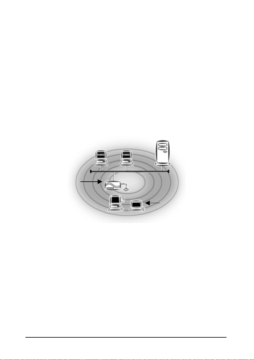
Type 2. The next simplest wireless network is very similar to the Type 1
network. This time the AP is connected to a wired Ethernet network as
a node. In this configuration the AP operates as a bridge between the
wired Ethernet network and th e wireless networks (F igure 2).
Wireless users have the same access to network resources as they
would have if they were wired. Such a configuration i s often used to
allow roaming, or to extend an existing network into a hard-to-wire
environment.
Wired Computers
Server
Wireless Computers
Figure 2. Single AP Network
Type 3. The third type of network is composed of multiple APs and multiple
stations (Figure 3).
16 InstantWave
11-Mbps Wireless Access Poin t
Page 17
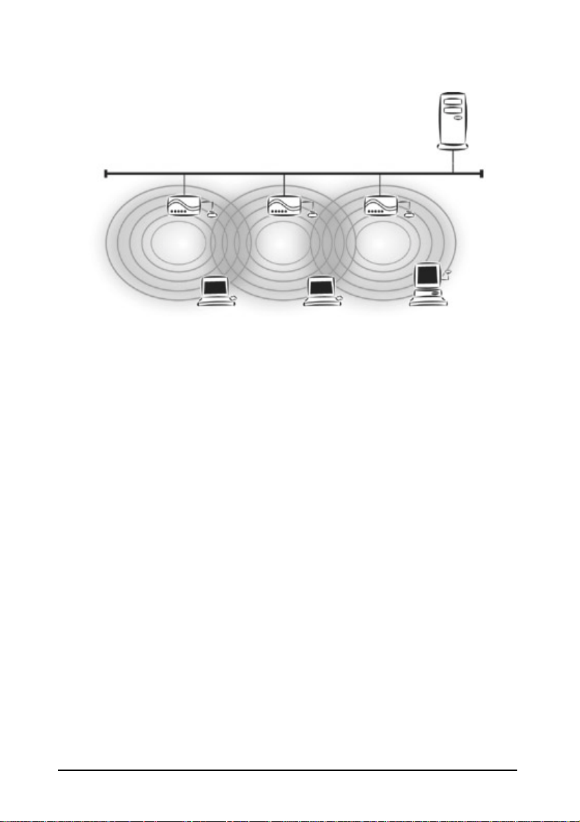
“Sales” Domain
Server
Wireless Cell A
AP-1 AP-3 AP-2
Station -1 Station -2 Station -3
Wireless Cell B
Wireless Cell C
Figure 3. Multiple-AP Network
The reasons for having multiple APs installed are:
1. To increase bandwidth in order to boost overall network performance
2. To extend the coverage range
Any other configuration is usually a mix of these commonly used types.
InstantWave
11-Mbps Wireless Access Point
17
Page 18

Planning an Infrastructure Network
This section explains some of the factors you need to consider when planning an
infrastructure network. Setting up is a two-step process:
1. Install and configure the InstantWave wireless products.
2. Decide the best physical location of the InstantWave wireless products so as to
optimize performance.
The following section gives quick guidelines for these two steps. First, decide
whether to have a single AP wireless network or a mul tiple AP network.
Single AP Installation
If you are setting up a sim ple netw ork with only on e AP and a f ew stat ions (a Type 1
or Type 2 network configuration as described in “Infrastructure Network Types,”
page 15), all you need to do is make sure the AP and all the wireless stations hold the
same domain name (SSID) and security (WEP) settings in their configuration.
Adding a new station to an existi ng infrastructur e network is eas y. Again, all you
need to do is to set the newly added station’s domain name (SSID) and security
(WEP) settings to be the same as those of the AP.
Multiple AP Installation
Installing multiple APs on the same network (or domain) with overlapping signals
(Figure 3, page 15
• Use the same domain name (SSID) and security (WEP) settings.
• Enable the Roaming function on stations that require it.
Note: A station will automatically connect to whichever AP in the same domain is
currently offering the best signal.
18 InstantWave
)
11-Mbps Wireless Access Poin t
Page 19

Roaming
InstantWave products allow wireless stations to roam freely within an infrastructure
domain composed of multiple APs with overlapping signal coverage (as in the Type
3 network configuration descr ibed in the previous section). For example, roaming
enables Station 1 to move from the AP 1 signal coverage area to the AP 2 signal
coverage area without disconnecting from the network. The handover is achieved
transparently; the Station 1 user woul d not real ize he had moved f rom AP 1 to AP 2.
The requirements for a roaming environment are:
a) Multiple APs with overlapping signal coverage (see “Multiple AP
b) The APs must be configured to have the same domain name (SSID) and
c) The mobile stations must have the same domain name (SSID) and security
It is advisable that APs on dif ferent TCP/IP subn ets be given diff erent domain names
to avoid roaming confusion (see the note below).
Note: For a mobile station t o move between APs without losing i ts netw ork link, the
Installation,” page 18)
security (WEP) settings (see “Encryption,” page 27).
(WEP) settings as the APs.
Roaming function must be e nabl ed on t he st ation, and the APs that t he s tati on
roams to must be configured with the same domain name. If a station detects
that the signal quality on the link to the current AP is poor, it will search for
an AP in the same domain with better signal quality and automatically
associate (establish a connection) with it. The station’s IP address, however,
will not change. A TCP/IP router will not route packets to a mobile station
that has associated with an AP on a different TCP/IP subnet. In other words,
if your network consist s of two subnets connect ed by a r outer, a mobile station
may roam to a different subnet with the same domain name and then be
unable to communicate with other network devices via TCP/IP. To avoid this
problem, you must assign dif fer ent domain names to diff er ent TCP/IP subnets .
InstantWave
11-Mbps Wireless Access Point
19
Page 20

Hardware Description
Figure 4. NWH660 Front Panel
LED Indicators
The NWH660’s LEDs show the status of the unit and its connections.
Figure 5. LED Indicators
LED Color Meaning
Power Green Off: Device not receiving power
Blinking: Diagnostic test in progress
On: Normal operation
Status Red Off: Normal operation
On: Normal operation interrupted
Ethernet Orange Off: No Ethernet link
On: Ethernet link up but idle
Blinking: Ethernet activity
Wireless Green Off: No wireless link
On: Wireless link up but idle
Blinking: Wireless activity
20 InstantWave
11-Mbps Wireless Access Poin t
Page 21

Connectors and Switches
Power Jack
Power Switch
Ethernet Port
Reset Button
Figure 6. NWH660 Rear Panel
Item Function
Power jack DC 5V power input
Power switch Device on/off
Ethernet port RJ-45 jack for connection to 10Base-T
Ethernet LAN
Reset button If held down more than 3 seconds,
reloads factory settings and restarts
device. Power LED will blink during
reset and then go off to indicate that
button can be released.
Serial port 9-pin D-shell connector for RS-232
connection to computer run ning AP
COMFig utility
Antenna connector Reverse SMA connector for antenna
Antenna Connector Serial Port
InstantWave
11-Mbps Wireless Access Point
21
Page 22

Hardware Pre-configuration
Before adding the NWH660 to an existing Ethernet network, you may need to set
basic parameters — e.g., SSID, security s ettings (WEP), A P n ame, ch ann el number,
and IP address — to make the AP compatible with the existing network.
From the AP COMFig utility:
Follow the steps below to connect the AP to a PC for configuration:
step 1. Connect the supplied RS-232 cable to the AP’s serial port and connect
the other end to a serial port (COM port) on the PC.
step 2. Power up the AP.
Or from IWMS:
The NWH660’s Ethernet port supports a speed of 10 Mbps. Using regular Category
3 or higher UTP/STP cable, you can connect it directly to a hub or switch.
step 3. Connect the NWH660 and your PCs/network devi ces to the Ethern et hub
or switch.
step 4. Power up the NWH660.
Installing the AP Management T ools
step 1. Insert disk 1 in drive A and click Start/Run. Type a:/menu.exe and click
OK to open the main menu.
step 2. Click Install AP Management Tools to install the AP COMFig Tool,
InstantWave Management System (IWMS) and Trap Server utility on
your system.
22 InstantWave
11-Mbps Wireless Access Poin t
Page 23
Using the AP COMFig T ool
The AP COMFig Tool is a Windows-based utility used to configure the AP via a
COM port connection between the AP and a PC . It provides th e following fun ctions:
• Sets AP parameters (e.g., IP address, domain name [SSID], security, etc.)
• Diagnoses the AP hardware and shows the results
• Upgrades the AP firmware
• Resets the AP configuration
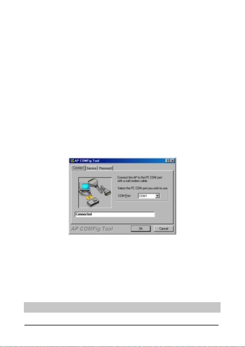
To start the AP COMFig Tool, click Start/Programs/InstantWave High Rate
AP/AP COMFig Tool. The program open s wi th the Connect panel displayed. It will
show Connected when a connection is made.
Figure 7. AP COMFig Tool/Connect
AP COMFig/Password
Click the Password tab to open the Password panel. Setting a password prevents
unauthoriz ed changes to the AP configuration set t ings.
Note: The password will be shared with the IWMS program on the same PC.
InstantWave
11-Mbps Wireless Access Point
23
Page 24

Figure 8. AP COMFig Tool/Password
AP COMFig/Service
After connecting with the AP, click the Service tab to open the Service panel (Figure
9). The Service panel provides access to AP management features.
Figure 9. AP COMFig Tool/Service
Click the Vie w and Modify AP Configuration button. The Configuration window
will open (Figure 10).
24 InstantWave
11-Mbps Wireless Access Poin t
Page 25

General:
The General panel (Figure 10) is the first panel in the Configuration section.
Figure 10. Configuration/General
On this panel, you can set and view general AP settings. These settings are explained
in the table below.
InstantWave
11-Mbps Wireless Access Point
25
Page 26

AP Alias Name
Domain Name
(SSID)
Transmission Rate
Basic Rates
Channel Number
Secure SSID
Regulatory Domain
BSSID
Firmware Version
Assigns the AP a unique human-friendly name
that allows the AP to be easily identified.
This is commonly called the domain name but
is defined in the IEEE 802.11b wireless
standard as SSID. Stations and APs in the same
group must use the same domain name.
Sets the transmission rate at which data packets
are transmitted by the AP.
This value determines the basic rates used and
reported for this BSS by t he AP. The highest
rate specified will be the rate that the AP will
use when transmitting broadcast/multicast and
management frames. Available options are:
• 1 and 2 Mbps
• All (1, 2, 5.5, and 11 Mbps)
You can change the channel number from here.
Refer to the Appendix, page 73, fo r channels
supported in each regulatory domain.
Click to enable or disable the secure SSID
option.
• Blocks a connection request from a
station without the correct SSID.
• Hides the SSID in outgoing beacon
frames. A site-survey tool will not
find the SSID.
Identifies the country where the AP is used.
Each country has defined its available channel
numbers and transmission power (see
Appendix, page 73)
This is the MAC ID of the AP
The current AP firmware version
Important:
In a multiple cell network topology, overlapping and/or adjac ent cells using different
channels can operate simultaneously without interference if the frequency distance
between the center frequencies is at least 30MHz. For example channels 1, 7, and 13
are non-overlapping frequency channels.
26 InstantWave
11-Mbps Wireless Access Poin t
Page 27

After making any changes, cli ck the Apply button to make the changes effective
immediately, without closing the dialog box, or click OK to accept the changes and
close the box.
Encryption:
Data encryption provides more secure wireless data communications. Click the
Encryption tab to create or change the security settings (Figure 11). The default is
Disabled and initially the keys section will be blank.
Figure 11. Configuration/Encryption
The dropdown Method box lists three options:
1. Disabled (default) - Disable data encryption
2. 40-bit WEP - Enable use of 40-bit WEP
3. 128-bit WEP - Enable use of 128-bit WEP
InstantWave
11-Mbps Wireless Access Point
27
Page 28

Key Generation - There are two ways to generate a security key.
The first is by entering any text in the Passphrase field. Click the Generate button.
For 40-bit WEP , it will generate four keys, Key 1, Key 2, Key 3, and Key 4. Select a
key number from the dropdown list of the Default Key box. If you do not manually
select a key , key 1 will be selected. For 128-bit WEP, only one key will be generated.
Click Apply.
Another WEP key generation me thod is to insert t he key values directly from the
keyboard. Enter your own ke y into one of the Key 1~4 fields. Select that field
number in the Default Key field. If the WEP key is enabled on the AP, all clients
must use the same WEP key. Click OK.
IP:
The InstantWave NWH660 is a DHCP client. It will automat ically try to get IP
settings from a DHCP server on the LAN. If it fails to get IP settings from a DHCP
server, it will assign itself an IP address in the 169.254.x.x range.
From the IP panel (Figure 12), you can assign an NWH660 a fixed IP address by
unchecking the Obtain IP from DHCP box. This lets you view or modify the access
point’s TCP/IP address, configure its subnet mask, or add a default gateway (see
note below).
Note: An AP will send SNMP response packets ( confirmation packets) dir ectly to an
IWMS PC if the two devices are on the same TCP/IP subnet. If an SNMP
response packet from an AP is destined for an IWMS PC on another subnet,
the SNMP response packet needs to go through a router or similar gateway.
The Default Gateway se tting is t he IP address of such a gateway. If you set the
correct defaul t gat ew ay, then you can use an IWMS PC physically located on
a different subnet to manage this AP.
28 InstantWave
11-Mbps Wireless Access Poin t
Page 29

If you assign a fixed IP addres s to an NWH 660, m ake sure t hat all NWH660s w ithin
the same net work have IP addresses on the same TCP/IP subnet.
Obtain IP from
DHCP
Automatically retrieves an IP address for the NWH660
from a Dynamic Host Configuration Protocol (DHCP)
server. This option is enabled by default
IP Address Manually assigns an IP address to the NWH660
Subnet Mask Manually assigns a subnet mask to the NWH660
Default Gateway Manually specifies the default gateway IP address (if
required)
If you wish to change the defaults, set each AP to its new IP address before
introducing it on the running network.
Figure 12. Configuration/IP
After making any changes, cli ck the Apply button to make the changes effective
immediately, without closing the dialog box, or click OK to accept the changes and
close the box.
Filter:
The next tab on the dialog box is Filter (Figure 13). This is a one-way protocol
filtering mechanism that prevents the AP from transmitting specified protocols from
InstantWave
11-Mbps Wireless Access Point
29
Page 30

a wired Ethernet LAN into the wireless LAN. If you do not require particular
protocols on the wireless part of your network, you can save bandwidth by enabling
the protocol filter.
Figure 13. Configuration/Filter
From the Filter panel, some, all, or none of the protocols listed may be selected for
filtering out:
• IP Protocol
• IPX Protocol
• NetBEUI Protocol
• AppleTalk Protocol
• Other Protocols
• Internet Multicast Frames
After selecting a protocol to be filtered, click the Apply button to make the changes
effective immediately, without closing the dialog box, or click OK to accept the
changes and close the box.
30 InstantWave
11-Mbps Wireless Access Poin t
Page 31

SNMP Access Control:
SNMP Access Control is the next tab on the box (Figure 14).
Figure 14. Configuration/SNMP Access Control
The AP’s access control is managed by a control table on the AP. The first time this
box is opened, the table will be empty. This means that there are no restrictions on
who can access and reconfigure the AP and any user may modify the AP’s operation.
To avoid ch aos on the network, access to the AP configuration should be rest ricted to
only those for who m it is necessar y.
Click Add to open the New En try dialog box (Figure 15).
Figure 15. New Entry
InstantWave
11-Mbps Wireless Access Point
31
Page 32

Two levels of access are available:
Read Read-only rights. The user may read everything
except the Access Control settings, but cannot
alter anything
Read/Write The user may read and alter all settings
Enter your IP address and then set your own access rights to Read/Write (see the
following note).
Note: Do not set all the stations in the Access Control table to Read-only. Once this
is set and enabled, it will be difficult to modify the AP. Should this situation
occur, use the AP COMFig utility to reset the configuration.
To set a s tations access rights, enter a station’s IP address and community string (the
community string is used as a password to access the AP) and choose Read or
Read/Write.
When all the settings are made, click OK to return to the Access Control panel. On
the Access Control panel, click the Apply button to make the changes effective
immediately, without closing the dialog box, or click OK to accept the changes and
close the box.
Perform AP Self Diagno stic Test
On the Service panel, click Perform AP Self Diagnostic Test. The Hardware
Diagnosis window will open (Figure 16).
32 InstantWave
11-Mbps Wireless Access Poin t
Page 33

Figure 16. Hardware Diagnosis
Click Start and the tests will commence. As each item is tested, a yellow arrow will
appear alongside it. If the test is successful, the arrow will change to a green check
mark. If a failure occurs, an “X” will appear. You can click Cancel at any time to
stop the tests. When the tests are finished, the Cancel button will change to a Close
button. Click Close to return to the Service panel.
Upgrade AP Firmware
From time to time updated firmware is released and may be downloaded from our
website at http://www.ndc.com.tw/support/support.htm
The updated firmware may be installed via a COM port using the AP COMF ig t ool.
Click on Upgrade AP Firmware (Figure 9, page 24). The Upgrade AP Firmware
dialog box will open (Figure 17).
Figure 17. Upgrade AP Firmware
InstantWave
11-Mbps Wireless Access Point
33
Page 34

Use the Browse button to choose the file to be uploaded to the AP, or type the file
location and name in the File Name field. The Upload button will then become
enabled. Click Upload. The new firmware will be loaded into the AP’s flash
memory area. When the file transfer is complete, click OK to begin the AP’s internal
firmware updating process.
Reset AP Configuration
Click Reset AP Configuration to open the dialog box shown in Figure 18, and cli ck
Reset to restore the factory default configuration to the access point.
Figure 18. Reset the AP Configuration
InstantWave Product Placement Guidelines
A few tips to mention that are particularly significant in a radio wave
communications system:
1. Radio waves reflect or refract from buildings, walls, metal furniture, or other
objects. This could result in performance degradation due to the fluctuation of
the received signal.
2. Microwave ovens use the 2.45-GHz frequency band. InstantWave also
functions in the 2.4 to 2.5- GHz band, and therefore sh ares some of the band w ith
microwave ovens. This means that when a nearby microwave oven is in use, it
may interfere with InstantWave signals, resulting in performance degradation
on the wireless network.
34 InstantWave
11-Mbps Wireless Access Poin t
Page 35

For the best performance, follow the guidelines below in placing the product:
• Place as high as possible, in as open an area as possible
• Avoid placing the AP (especially the antenna) close to metal objects (e.g. file
cabinets, metal cubicles, etc.)
• Keep APs and stations as far away as possible from microwave ovens (10
meters min. is advisable)
When you have decided on a location, follow the steps below to complete the
installation.
step 1. Screw the antenna into the back of the AP. Place the AP in the chosen
location.
step 2. Connect one end of an Ethernet network cable to th e UTP port of th e AP,
and the other end to an Ethernet hub or switch.
step 3. Connect the power adapter to the electricity outlet and then to the access
point’s DC-In jack.
step 4. Turn on the AP’s power switch.
InstantWave
11-Mbps Wireless Access Point
35
Page 36

Installing the InstantWav e Management System
step 1. Insert the InstantWave Management System disk into floppy drive A:.
Click Start/Run and type a:\setup.exe. The setup program will prepare
the InstallShield Wizard and then display a Welcome window.
step 2. Click Next.
36 InstantWave
11-Mbps Wireless Access Poin t
Figure 19. Welcome
Page 37

Figure 20. Important Issues
step 3. Older operating systems may need to update some system files to
function correctly with the InstantWave Management System. If required,
follow the on-screen instructions to download the required file (Figure
20). Click Next to open the Choose Destination Location window
(Figure 21).
Figure 21. Choose Destination Location
step 4. Click Next.
InstantWave
11-Mbps Wireless Access Point
37
Page 38

Figure 22. Select Program Folder
step 5. Click Next again (Figure 22).
Figure 23. Setup Complete
step 6. Check “I would like to launch InstantWave Manageme nt System” and
click Finish.
38 InstantWave
11-Mbps Wireless Access Poin t
Page 39

Using the InstantWav e Management System
Once the NWH660 is connected to an Ethernet netw ork, a network administrator can
connect to it from any PC on the same network via the InstantWave Management
System (IWMS) utility.
The IWMS utility is a Windows-based SNMP management tool allowing network
administrators to remotely configure and monitor the NWH660 through both an
Ethernet and a wireless connec tion. To launch the IWMS utility:
step 1. Click Start/Programs/InstantWave/Management System/InstantWave
Management System. The main IWMS window will open. Click
Start/Start Hosts View.
Auto-Discovery
This discovery protocol can discover all InstantWave wireless operating devices
connected to the Ethernet LAN within the same subnet.
step 1. Click the Auto Discovery icon (a pair of binoculars) on the left side of the
Hosts View window. All working InstantWave devices will automatically
be discovered (Figure 24).
InstantWave
11-Mbps Wireless Access Point
39
Page 40

Figure 24. InstantWave Management System
step 2. Select one of the wireless devices on the list. The utility buttons on the
left toolbar will be enabled (Figure 25).
step 3. Right-clicking on a particular device will open a popup menu of fering the
same functions as the toolbar.
40 InstantWave
11-Mbps Wireless Access Poin t
Page 41

Figure 25. Popup Menu
Configuration
step 1. For configuration, select the AP (NWH660) on the Hosts View wi nd ow
(Figure 24)
step 2. Right-click the NWH660 to open the popup menu
step 3. Click Config to go to the configuration dialog box (Figure 26)
InstantWave
11-Mbps Wireless Access Point
41
Page 42

Figure 26. IP Configuration
IP
IP Address Setting: The InstantWave NWH660 is a DHCP client. It will
automatically ask the DHCP server to assign it an IP address. An administrator can
assign a fixed IP to an NWH660 by unchecking the Obtain IP from DHCP box
(Figure 26). You may also configure a subnet mask and add a default gateway.
If you assign a fixed IP addres s to an NWH 660, m ake sure t hat all NWH660s w ithin
the same net work have the same TCP/IP subnet addre ss.
Obtain IP from
DHCP
Automatically retrieves an IP address for the NWH660
from a Dynamic Host Configuration Protocol (DHCP)
server. This option is enabled by default
IP Address Manually assigns an IP address to the NWH660
Subnet Mask Manually assigns a subnet mask to the NWH660
Default Gateway Manually specifies the default gateway IP address (if
required)
Note: An NWH660 will directly transfer SNMP response packets (confirmation
packets) to an IWMS PC if it is within the same LAN (the same subnet mask).
If an SNMP re sponse packet fr om an NWH660 is des tined for an IWMS PC o n
42 InstantWave
11-Mbps Wireless Access Poin t
Page 43

another LAN, the SNMP response packet needs to be forwarded by routers.
The default gateway is the closest r outer to the NWH660. If the corr ect def ault
gateway is set, you can use an IWMS manager (i.e. a PC running IWMS)
physically located in a different subnet to manage this NWH660.
Filter
The next panel in the configuration dialog box is Filter (Figure 27).
Figure 27. Configuration/Filter
This is a one-way protocol filtering mechanism that prevents the NWH660 from
transmitting specified protocols packet from a wired Ethernet LAN into the wireless
LAN. If you do not require pa r ticu lar protocol s on t he wireless part of your network,
you can save bandwidth by enabling the protocol filter.
From the Filter panel, some, all, or none of the protocols listed may be selected for
filtering out:
• IP Protocol
• IPX Protocol
InstantWave
11-Mbps Wireless Access Point
43
Page 44

• NetBEUI Protocol
• AppleTalk Protocol
• Other Protocols
• Internet Multicast Frames
Wireless
The Wireless panel (Figure 28) provides access to the Wireless settings.
Figure 28. Configuration/Wireless
These settings are explained in the following table.
Name
SSID
Assigns the NWH660 a unique name t hat allows the
AP to be easily identified on the network.
Identifies the wireless LAN domain that this AP is in.
A domain is generally composed of wireless APs you
are most likely to communicate with. You can type an
existing domain name or create a new one that
contains up to 32 characters.
44 InstantWave
11-Mbps Wireless Access Poin t
Page 45

Broadcast
SSID
Transmission
Rate
Basic Rates
Channel
Number
Regulatory
Domain
Click to enable or disable the SSID broadcasting
feature: If disabled, the NWH660 will:
• Blocks a connection request from a station
without the correct SSID
• Hides the SSID in outgoing beacon frames.
A site-survey tool will not find the SSID
Sets the transmission rate at which the data packets
are transmitted by the NWH660. In high-interference
environments a lower rate can increase overall
transmission speed by reducing resends of lost
packets
This value determines the basic rates used and
reported for this BSS by the NWH660. The highest
rate specified is the rate that the NWH660 will use
when transmitting broadcast/multicast and
manageme nt frames.
Available options are:
• 1 and 2 Mbps
• All (1, 2, 5.5, and 11 Mbps)
You can change the channel number from here.
Refer to the Appendix, page 73, fo r channels
supported in each regulatory domain.
If the “auto” option is selected, the access point can
choose the best available radio channel automatically.
Identifies the country where the NWH660 is used.
Each country has defined its available channel
numbers and transmissi on power (see Appen dix, page
73)
Important:
In a multiple cell network topology, overlapping and/or adjacent cells using diff erent
channels can operate simultaneously without interference if the difference between
the center frequencies is at least 30 MHz. For example, channels 1, 7, and 13 are
non-overlapping frequency channels.
InstantWave
11-Mbps Wireless Access Point
45
Page 46

MAC Access Control
This feature lets you limit access to the network through the access point. You can
list up to 1000 stations that are to be granted or denied access. A drop- down box lets
you select the method of access control:
• Disabled: Disable MAC-address access control. This is the default setting.
• Accepted List: Only wireless stations whose MAC addresses are on the list
are allowed to connect through the access point.
• Denied List: Wireless stations whose MAC addresses are on the list are
prevented from connecting through the access point.
To add a wireless station to the list, click the New MAC Address icon (a sheet of
paper with one corner f olded) on th e left si de of the MA C Access Cont rol panel. You
will be prompted to enter:
• The wireless station’s MAC address.
• A name for the station.
• The status of the station’s entry on the list. Check the Not Use box to
reverse the effect of access control on this station (for example, to deny
access if Accepted List [see above] is selected). Clear the box to let the
selected method of access control take effect on this station. This box has
no effect if MAC-address access control is disabled.
46 InstantWave
11-Mbps Wireless Access Poin t
Page 47

Figure 29. Configuration/Mac Access Control
Wireless stations registered in the MAC Address Control Table can be individually
turned on or off . For exam ple, if you h ave enabled th e Accepted L ist option , y ou can
check the Not Use option for any listed station; the access point will then refuse all
connection attempts from that station.
MAC Address List:
Status
Address
Identifier
Disables or enables an individual entry
The MAC address of a wireless station
Identification for the wireless station
New: Click New to create a new entry in the MAC Address List.
Delete: Click Delete to remove a selected MAC address from the list.
Delete All: Click Delete All to remove all of the MAC addresses from the list.
InstantWave
11-Mbps Wireless Access Point
47
Page 48

Encryption
Click the Encryption tab (Figure 30) to set up the security options.
Figure 30. Configuration/Encryption
The default setting is Disabled and initially the key sections are blank.
The pull-down Method box lists three options:
• Disabled (default) - Disable data encryption
• 40-bit WEP - Enable use of 40-bit WEP
• 128-bit WEP - Enable use of 128-bit WEP
Key Generation - There are two ways to generate a security key. The first is by
entering any text in the Passphrase f ield. Click the Generate button. For 40- bit WEP,
it will generate four k eys, Key 1, Key 2, Key 3, and Key 4. S elect a key number f rom
the dropdown list of the Default Key box. If you do not manually select a key, key 1
will be selected. For 128-bit WEP, only one key will be generated. Click OK.
48 InstantWave
11-Mbps Wireless Access Poin t
Page 49

Another WEP key generation me thod is to insert t he key values directly from the
keyboard. Enter your own ke y into one of the Key 1~4 fields. Select that field
number in the Default Key field.
SNMP Access Control
The AP contains an SNMP access table to limit access to its configurations. By
default there is no restriction on accessing the AP. To avoid chaos on the network,
access to the NWH660 configuration should be restricted to only those who require
access.
When you select SNMP Access Control, the system will display four blank wireless
devices for setting (maximum of 4 SNMP devices can be set). Right-click on a
device in the list and click Edit Address (Figure 31).
Figure 31. Configuration/SNMP Access Control
The New/Edit Address dialog box will open (Figure 32).
InstantWave
11-Mbps Wireless Access Point
49
Page 50

Figure 32. New/Edit Address
Two levels of access may be assigned:
Read Read-only rights. The user may read everything
except the Access Control settings, but is not
allowed to alter anything
Read/Write The user may read and alter all settings
Enter your PC’s IP address and then set your own access rights to Read/Write (see
the following note).
Note: Do not set all the stations in the Access Control table to Read only . Once this is
set and enabled, it will be impossible to modify the NWH660. Should this
situation occur, press the Reset button on the rear of the NWH660 to restore
the factory configuration.
To set a stations access rights, enter a station’s IP address and password (the
community string is used as a password to access the NWH660) an d choose Read or
Read/Write.
When a setting is made, click OK. Repeat the procedure for the next PC. When all
settings are made, click OK in the configuration dialog boxto make the changes
effective.
Trap Server
When the NWH660 is powered on, or an Et h ern et port becomes active, an event log
will be generated indicating the time, the IP address of the reporting NWH660, and
50 InstantWave
11-Mbps Wireless Access Poin t
Page 51

the event. You can save, open, and delete log files from the File menu.
To assign a trap server, click Trap Server (Figure 33).
Figure 33. Configuration/Trap Server
Assign a station as a trap server by entering its IP address and network port type.
Click Edit address.
To remove a trap server from the list, highlight it and click Clear address. Click
Clear all address to remove all assigned trap servers from the list (Figure 34).
Figure 34. Configuration/Clear all Address
InstantWave
11-Mbps Wireless Access Point
51
Page 52

To v iew trap log information, click the Start Trap View icon (a ringing telephone) in
the upper left corner of the main IWMS window (see Figure 24, page 40). A window
such as that shown below will appear (Figure 35).
Figure 35. Trap View
The log shows when an NWH660 was powered on, or an Ethernet port became
active, and the IP address of t h e repo rt in g N WH660. Y ou can s av e , open , an d dele te
log files through the File men u.
Important:
Once all configurations have been completed, click OK. You w ill be reminded that a
reset is required to make the changes effective. Click Yes.
Figure 36. Warning
52 InstantWave
11-Mbps Wireless Access Poin t
Page 53

Monitor
The Monitor tool allows the NWH660’s status, Eth ernet statistics, wirel ess statistics,
and other configuration information to be viewed/monitored.
In the Hosts View window (Figure 37), select a device and click the Monitor button
on the toolbar or on the popup menu.
Figure 37. Monitor
An information window will appear. The first of three panels in this window, the
Summary panel, will be visible (Figure 38).
InstantWave
11-Mbps Wireless Access Point
53
Page 54

Figure 38. Monitor/Summary
Summary Information
The information shown is read-only.
Device Name IWMS system default category name
Name Human-friendly name assigned by
the user for easier identification
S/W Ver s i on Shows the devic e software version
number
H/W Ve rsion Shows the device hardware ver s i on
number
Channel Shows the wireless channel currently
in use on the device
Current BSSID Shows the BSSID of the device (same
as the device MAC address)
Statistics
The Statistics window shows both Ethernet and wireless transmission/reception
statistics. To refresh the statistics, click on the !button to continually refresh
information. Click on the"button to stop upda te information.
54 InstantWave
11-Mbps Wireless Access Poin t
Page 55

Figure 39. Monitor/Statistics
The Connected Wireless Stations window lists all the currently associated wireless
station’s Media Access Control (MAC) addresses. When fi nished viewing, click X
to close the window.
Figure 40. Monitor/Stations
InstantWave
11-Mbps Wireless Access Point
55
Page 56

Reset
Resetting the NWH660 will take about 30 seconds (Figure 41).
Figure 41. Reset the AP Configuration
During this period, the IWMS program will n ot be able to que ry the NWH660 vi a the
SNMP protocol and the NWH660 will not be available to its client stations.
If you try to access the device, the IWMS program will display the message
“Timeout! No response from agent . . .”
Load Default
Click Load Default if you want to return the device to its factory default settings.
A warning dialog box will open (Figure 42).
Figure 42. Load Default
Click Yes to return the NWH660 to the factory default settings.
Note: The NWH660 will be reset to complete the ‘Load Default’ operation.
Upgrade Firmware
The NWH660’s embedded software is contained in “flash” ROM, and can be
updated over your LAN via the IWMS program. To download new embedded
software to the device, click Upgrade Firmwar e. The Upgrade Fi rmwar e dialog box
will open (Figure 43).
56 InstantWave
11-Mbps Wireless Access Poin t
Page 57

Figure 43. Upgrade Firmware
Browse for the file to be uploaded to the NWH660, or type the path and file name
into the Select File field.
The Upgrade button will then become enabled. Click Upgrade to start downloading
the file to the NWH660. The IWMS and the NWH660’s built-in Trivial File
Transfer Protocol (TFTP) client/server will load the new executable into the
NWH660’s f lash ROM area. If th e down load activ ity fails , an error m e ssage w ill be
shown in the message box. Once the file transfer is complete, click Close to close
the window.
InstantWave
11-Mbps Wireless Access Point
57
Page 58

Advanced Settings
Batch mode operation
In order to maximize the efficiency of wireless LAN management, y ou can use batch
mode operation to manage selected APs or WEBs. You can sort InstantW ave devices
by device type first. Then select the multiple APs or WEBs you would like to
manage. Next, click the right mouse button to open the tool bar; then choose the
functional tool you would like to use to work on these specific APs or WEBs.
Figure 44. Batch Mode Operation List
Manage IWMS Host Table
Partition the network according to the physical location
The Host Table is a very powerful function to support the massive deployment of
InstantWave products. You can combine several APs toghther with WEBs to form a
58 InstantWave
11-Mbps Wireless Access Poin t
Page 59

group with a specific Host Table name so that you can divide the wireless network
into many small groups. A wireless LAN in the hotel application will be a typical
example.
InstantWave
Product
Device
Type
Alias Name
Host Table
Name
Explanation
NWH660 AP AP1-A-1F A-1F AP on first floor of
building A
NWH660 AP AP2-A-1F A-1F AP on first floor of
building A
NWH6210 WEB Room111 A-1F AP on first floor of
building A
NWH6210 WEB Room112 A-1F AP on first floor of
building A
NWH660 AP AP1-B-1F B-1F AP on first floor of
building B
NWH660 AP AP2-B-1F B-1F AP on first floor of
building B
NWH6210 WEB Room111 B-1F AP on first floor of
building A
NWH6210 WEB Room121 B-1F AP on first floor of
building A
The wireless LAN is installed on the first floor of building A and the first floor of
building B. You can assign a different Host Table for each wirele ss installation
group. Once the wireless LAN is divided into many small groups. You can easily
manage each wireless LAN group by managing its H ost Table respectively.
Create Host Table via Automatic Discovery
Click “Automatic Discovery” to find all InstantWave devices. Select the desired
APs and WEBs (for example, those on the first floor of building A). Click the right
mouse button to open the tool bar. Choose “Export Host table” to save the Host
Table to a file (for convenience, you can save the Host table on a network disk for
ease of access).
InstantWave
11-Mbps Wireless Access Point
59
Page 60

Import Host Table to check device’s availability
Import the Host Table from a file (for convenience, you can retrieve the Host table
on a network disk for the ease of access). Once the Host Table is imported, IWMS
will automatically check the availability of APs and WEB s listed in t he Host Table.
This is an extremely powerful feature to make up for the inadequacy of
Auto-Discovery. Auto-Discovery can only find InstantWave devices when they are
alive. Failed devices cannot be found via Auto-Discovery. The devices listed in the
Host Table should be available and provide the service. If th ey do not exist, IWMS
can report their absence immediately so that the system administrator can take
immediate action.. The following chart is a typical example. The device with IP
address 192.168.1.190 is not responding.
Figure 45. Import Host Table to Check Device
New/Edit/Delete a Host Address on Host Table
Click the Add new address under IW MS but ton to open the New/Edi t Address dial og
box (Figure 46). Only IP address is necessary for entering. IWMS will automatically
find AP’s and WEB’s hardware address and device type.
60 InstantWave
11-Mbps Wireless Access Poin t
Page 61

Figure 46. New/Edit/Delete a Host Address
From here you can also select any AP or WEB on the table. Edit it for the
modification or delete it whenever it is no longer necessary. This table can be saved
and retrieved from the IWMS utility so that you don’t need to create such a table
again in the IWMS utility.
Export the Configuration prof ile t o a File
The configuration file can be saved to a text file and safely kept. This configuration
file can also be imported to recover the InstantWave Product’s setting, if there is an
accident. This profile can also be copied to the other InstantWave product of the
same kind. To do this, first click the Export button in the Configuration window.
Then enter the file name for the configuration profile to be saved to.
Figure 47. Export the Configuration Profile to a File
InstantWave
11-Mbps Wireless Access Point
61
Page 62

Import the Configuration Profile from a File
If there is an accident, the configuration file can also be imported to recover the
InstantWave product’s original settings. This profile can also be copied to the other
InstantWave product of the same kind. To do this, first click the Import button in the
Configuration window. Then; enter the file name for the configuration profile to be
imported from. The user can also pre-select the session of the network profile to be
imported and over-written first before clicking the Import button.
Figure 48. Import the Configuration Profile from a File (1)
Figure 49. Import the Configuration Profile from a File (2)
62 InstantWave
11-Mbps Wireless Access Poin t
Page 63

Figure 50. Import the Configuration Profile from a File (3)
Encryption
The configuration file does not contain the security key settings. The
attributes of security keys are externally write-only and cannot be saved
into the configuration file. Click Encryption to set up the security keys
manually.
InstantWave
11-Mbps Wireless Access Point
63
Page 64

FAQs
The FAQs section attempts to answer the most commonly asked questions about
InstantWave wireless access points.
Question Answer
At what radio frequency
does an AP
communicate?
How do I secure the data
crossing an AP's radio
link?
What is the speed of the
AP's Ethernet port?
What are possible
sources of interference
for the radio frequency
link of the AP?
How do I set the AP back
to its factory default
settings?
What security features does
the AP support?
In the U.S., wireless LAN radios transmit and receive
on one of 11 channels in the 2.4-GHz frequency band.
This is a public band, and does not require a license
from the FCC.
Enable the Wired Equivalency Protocol (WEP) to
encrypt the payload of packets sent across a radio link.
The AP's Ethernet port (RJ-45 jack) supports 10 Mbps
over a 10Base-T connection (half-duplex only).
Interference can come from a number of sources,
including 2.4-GHz cordless phones, improperly
shielded microwave ovens, and wireless equipment
manufactured by other companies. Police radar, electric
motors, and moving metal parts of m ach inery can cau s e
interference too.
You can load default settings from the menu of the
InstantWave Management System (IWMS), a
Windows-based SNMP management tool. You may also
press the reset button on the back panel of the AP.
SSID: By disabling the “Broadcast SSID” option
Data security: The AP supports 40-bit and 128-bit Wired
Equivalent Protocol (WE P).
Management Security: SNMP Access Control
64 InstantWave
11-Mbps Wireless Access Poin t
Page 65

T roubleshooting
This section provides you wit h some troubleshoot ing info should you encounter
installation or operation problems on InstantWave products. If the problems still
cannot be remedied after going through the Troubleshooting section, check the
FAQs on page 64 of this manual and at http://www.ndc.com.tw/support/faq.htm
If your problems still cannot be remedied after going through the FAQs and this
Troubleshooting section, contact NDC technical support for assistance (see
“Technical Support,” page 67).
Symptom Suggested Solutions
The NWH660 is swit ched
on, but the Power LED
on the NWH660 is off.
The IWMS utility cannot
detect an InstantWave
NWH660 on the same
network.
The NWH660 powers up,
but the Ethernet Link
LED is off (no
connection to an
Ethernet network).
The Status LED on the
NWH660 front panel is
red and flashing.
1. Make sure the power adapter is firmly connected to
the power outlet and the NWH660 power connector.
2. The power adapter or NWH660 is defective.
1. Make sure the NWH660 is powered on and
connected to an Ethernet work.
2. Check the IP addresses assign ed to the NWH660 and
IWMS terminal PC. They should be in the same
subnet and unique. For ex ample, if th e NWH660’s IP
address is 192.168.1.5 w ith a mask of 255.255.255.0,
then the PC’s IP address should be 192.168.1.x with
a mask of 255.255.255.0.
Make sure:
1. The Ethernet cable is connected firmly to both the
AP and hub or switch.
2. The Ethernet hub or switch is powered on.
Restart (power-cycle) the NWH660 and check the
Status LED again. If it is still flashing, you need to
return the NWH660 to the reseller for repair.
InstantWave
11-Mbps Wireless Access Point
65
Page 66

Transmission
performance is slow or
erratic.
1. Change the direction of the antenna slightly.
2. There may be interference, possibly caused by a
microwave oven, 2.4-GHz wireles s phone, or m etal
objects. Move these interference sources or change
the location of the wireless PC or AP.
3. Change the wireless channel on the NWH660.
4. Check that the NWH660 antenna, connectors, and
cabling are firmly connected.
66 InstantWave
11-Mbps Wireless Access Poin t
Page 67

T echnical Sup port
Support from Your Network Supplier
If assistance is required, call your supplier for help. Have the following information
ready before you make the call.
1. LED status
2. A list of the product hardware (including revision leve ls), and a brief desc ription
of the network structure
3. Details of recent configuration changes, if applicable
Support from NDC
If you have any problems that you cannot resolve with the information in
troubleshooting, or the FAQs at
http://www.ndc.com.tw/support/faq.htm
please note the following information and contact our technical support team:
• What you were doing when the error occurred
• What error messages you saw
• Whether the problem can be reproduced
• The serial number of the product
• The firmware version and the debug information
NDC Technical Support is available via: E-mail: techsupt@ndc.com.tw
From time to time updated firmware is released and may be downloaded from the
following URL: http://www.ndc.com.tw/support/support.htm
For other information about NDC, please visit us at: www.ndclan.com
InstantWave
11-Mbps Wireless Access Point
67
Page 68

NDC Limited Warranty
Hardware
NDC warrants its products to be free of defects in workmanship and materials,
under normal use and service, fo r a period of 12 months from the date of purchase
from NDC or its Authorized Reseller, and for the period of time specified in the
documentation supplied with each product.
Should a product fail to be in good working order during the applicable warranty
period, NDC will, at its option and expense, repair or replace it, or deliver to the
purchaser an equivalent product or part at no additional charge except as set forth
below. Repair parts and replacement products are furnished on an exchange basis
and will be either reconditioned or new. All replaced products and parts will become
the property of NDC. Any replaced or repaired product or part has a ninety (90) day
warranty or the remainder of the initial warranty period, whichever is longer.
NDC shall not be liable under this warranty if its testing and examination disclose
that the alleged defect in t he product does not exis t or was caused by th e purchase r’s,
or any third p arty’s misuse, neglect, improper installation or testing, unauthorized
attempt to repair or modify, or any other cause beyond the range of the intended use,
or by accident, fire, lightning, or other hazard.
Software
Software and documentation materials are supplied “as is” witho ut warranty as to
their performance, merchantability, or fitness for any particular purpose. However,
the media containing the software is covered by a 90-day warranty that protects the
purchaser against failure within that period.
68 InstantWave
11-Mbps Wireless Access Poin t
Page 69

Limited Warranty Service Procedures
Any product (1) received in error, ( 2) in a defective or non-functioning condition, or
(3) exhibiting a defect under normal working conditions, can be returned to NDC by
following these steps:
You must prepare:
!" Dated proof of purchase
!" Product model number and quantity
!" Product serial number
!" Precise reason for return
!" Your name/address/email address/telephone/fax
1. Inform the distributor or retailer.
2. Ship the product back to the distributor/retailer with prepaid freight. The
purchaser must pay the shipping fee from the distributor/retailer to NDC. Any
package sent C.O.D. (Cash On Delivery) will be refused.
3. Charges: Usually RMA (Returned Material Authorization) items will be
returned to the purchaser via airmail, prepaid by ND C. If returned by another
carrier, the purchaser will pay the difference. A return freight and handling fee
will be charged to the purchaser if NDC determines that the product was not
faulty or that the damage was caused by the user.
Warning
NDC is not responsible for the integrity of any data on storage equipment (hard
drives, tape drives, floppy diskettes, etc.). We strongly recommend that our
customers back their data up before sending such equipment in for diagnosis or
repair.
InstantWave
11-Mbps Wireless Access Point
69
Page 70

Services after Warranty Period
After the warranty period expires, all products can be repaired for a reasonable
service charge. The shipping charges to and from the NDC facility will be borne by
the purchaser.
Return for Credit
In the case of a DOA (Dead on Arrival) or a shipping error, a return for credit will
automatically be applied to the purchaser’s account, unless o therwise requested.
Limitation of Liability
All expressed and implied warranties of a product’s merchantability, or of its fitness
for a particular purpose, are limited in duration to the applicable period as set forth in
this limited warranty, and no warranty will be considered valid after its expiration
date.
If this product does not fu nction as warranted, your sole remedy shall be repair or
replacement as provided for above. In no case shall NDC be liable for any incident al,
consequential, special, or indirect damages resulting from loss of data, loss of profits,
or loss of use, even if NDC or an authorized NDC distributor/dealer has been
advised of the possibility of such damages, or for any claim by any other party.
70 InstantWave
11-Mbps Wireless Access Poin t
Page 71

Specifications
General
Regulatory Compliance
Standards
Data Rate
Communication Method
Security
LED Indicators
Interfaces/Connectors
Power
Dimensions
FCC Part 15 Class B (U.S.)
Wireless LAN: IEEE 802.11b, Wi-Fi Compliant
Ethernet: IEEE 802.3
11, 5.5, 2, and 1 Mbps, with auto fallback
Half-duplex
40-bit and 128-bit WEP data encryption
Power, Status, Ethernet, Wireless
10Base-T: RJ-45
Reverse-type SMA Ant e nna C o nnec to r
Input Voltage: 5.1 volts DC ±5%
AC Adapter Input: 100 to 24 0 volts AC
Power Consumption: 5.1 volts, 1.0 amperes
(typical)
220 x 145 x 33 mm (8.66 x 5.71 x 1.30 in.)
InstantWave
11-Mbps Wireless Access Point
71
Page 72

Wireless Specifications
Emission Type
Radio Frequency Range
Transmitter
Receiver Sensitivity
Antenna Type
Software
SNMP Functions
Direct Sequence Spread Spectrum
2471 to 2497 MHz (Japan)
2400 to 2483.5 MHz (Nort h A merica, Eu rope, and
Extended J apan Band)
2445 to 2475 MHz (Spain)
2446.5 to 2483.5 MHz (France)
RF Output Power: 20 dBm
Frequency Stability: Within ±25 ppm
Data Modulation Type: BPSK (1 Mbps), QPSK
(2/5.5/11 Mbps)
Data Modulation Speed: 11/5.5/2/1 Mbps with
auto fallback
-83 dBm at 11 Mbps
Dual dipole diversity antenna (fixed or external)
Configuration and management via SNMP in a
Microsoft Windows environment through
Ethernet or wireless
Security
Firmware Upgrade
Environment
Temperature
Humidity
72 InstantWave
MIB II (RFC 1213), Bridge MIB (RFC 1493),
Enterprise MIB
WEP data encryption
SNMP access control
Firmware upgrade through Etherne t or wireless
Operating: 0° to 50° C (32° to 122° F)
Storage: -30° to 70° C (-22° to 158° F)
85% at 40° C (104° F)
11-Mbps Wireless Access Poin t
Page 73

Appendix
This appendix lists the channels supported by the world’s regulatory domains.
The channel numbers, channel center frequencies, and regulatory domains are
shown in the table.
Channel
Number
1 2412 O O O
2 2417 O O O
3 2422 O O O
4 2427 O O O
5 2432 O O O
6 2437 O O O
7 2442 O O O
8 2447 O O O
9 2452 O O O
10 2457 O O O O O
11 2462 O O O O O
12 2467 O O O
13 2472 O O O
14 2484 O
Center
Frequency
(MHz)
FCC/
Canada
ETSI Spain France Japan
InstantWave
11-Mbps Wireless Access Point
73
Page 74

Index
Access Control.............................31
Access Rights............................... 31
Alias Name................................... 26
AP COMFig
Password................................... 23
Service...................................... 24
AP COMFig Tool
Using........................................23
APMS Host Table......................... 60
Basic Rates............................. 26, 45
Broadcast SSID............................ 45
BSSID .................................... 13, 26
Channel Number .................... 26, 45
Channels
Non-overlapping................. 26, 45
Configuration ............................... 41
Default Gateway........................... 28
IP Setting ................................28, 42
LEDs.............................................20
Load Default.................................56
MAC Access Control....................46
MAC Address...............................55
MAC Address List........................47
MAC ID........................................13
Media Access Control ID .............13
Modify AP Configuration.............24
Monitor.........................................53
Network
Infrastructure.............................15
Multiple APs .............................16
Packing List...................................iii
Password/AP COMFig .................23
Placement Guidlines.....................34
Placing
Domain Name .............................. 26
Encryption...................13, 27, 48, 63
Filter............................................. 43
Filter Protocols............................. 29
Firmware Version......................... 26
Flash ROM................................... 33
General......................................... 25
Generate ....................................... 48
Host Table .................................... 60
74 InstantWave
11-Mbps Wireless Access Poin t
for performance ........................35
Protocol Filtering..........................29
Radio Frequencies ........................13
Regulatory Domains.........13, 26, 45
Reset .............................................56
Reset AP Configuration................34
Roaming.......................................19
Secure SSID..................................26
Self Diagnostic Test ......................32
Page 75

Service Set ID............................... 26
Trap Log Information ...................52
Service/AP COMFig .................... 24
SNMP Access Control............ 31, 49
SSID....................................... 13, 44
Statistics ....................................... 54
Subnet Mask ................................. 28
Summary Information.................. 54
System Requirements ................... 12
TCP/IP Address............................ 28
Transmission Rate.................. 26, 45
Trap Server................................... 50
Upgrade AP Firmware (AP COMFig
Program)...................................33
Upgrade Firmware........................56
View/Modify AP Configuration ...24
WEP..............................................13
Wired Equivalent Privacy.............13
Wireless........................................44
InstantWave
11-Mbps Wireless Access Point
75
 Loading...