

Page 1

g
High Rate
11Mbps Wireless Networkin
Access Point
User’s Guide
December 2001
NWH650
Rev. A1
National Datacomm Cor pora tio n
4F, No. 24-2, Industry East 4th Road, Science Park
Hsin-Chu, Taiwan, R.O.C.
Technical Support
E-mail: techsupt@ndc.com.tw
NDC World Wide Web
www.ndc.com.tw
Page 2

TRADEMARKS
NDC and InstantWave are trademarks of National Datacomm Corporation. All other
names mentioned in this document are trademarks/registered trademarks of their
respective owners.
NDC provides this document “as is”, without warranty of any kind, neither expressed nor
implied, including, but not limited to, the particular purpose. NDC may make improvements
and/or changes in this manual or in the product(s) and/or the program(s) described in this
manual at any time. This document could include technical inaccuracies or t ypographical
errors.
FCC WARNING
This equipment has been tested and found to comply with the limits for a Class B Digital
device, pursuant to part 15 of the FCC Ru les. These limits are designed to provide
reasonable protection against harmful interference in a residential installation. This
equipment generates, uses, and can radiate radio frequency energy and, if not installed and
used in accordance with the in st ructions, may cause harmful interfer ence to radio
communications. However, there is no guarantee that interference will not occur in a
particular installation. If this equipment does cause harmful interference to radio or
television receptio n, which can be determined by turni ng the equipment off and on, th e user
is encouraged to try to correct t he interference by one or more of the following measures:
Reorient or relocate the receiving antenna
Increase the separation bet ween t he equipment and receiver
Connect the equipment into an outlet on a circuit differen t from that to which the
receiver is connected
Consult the dealer or an experienced radio/TV technician for help
You are cautioned that changes or modifications not expressly approved by the party
responsible for compliance could void your authority to operate the equipment.
This device complies with part 15 of the FCC Rules. Operation is subject to the following
two conditions:
1. This device may not cause harmful interference, and
2. This device must accept any interference received, including interference that may
cause undesired operation
FCC RF Radiation Exposure Statement
This equipment complies with FCC RF radiation exposure limits set forth for an
uncontrolled environment. This equipment should be installed and operated with a
minimum distance of 20 centimeters between the radiator and your body.
ii InstantWave High Rat e 11Mbps Access Point
Page 3

Packing List
The package should contain the following items:
• One NWH650 InstantWave High Rate Access Point
• One RS-232 Cable
• One RJ-45 Cable
• One Power Adapter
• One CD ROM (Contains drivers, Station utilities, Access Point
manageme nt tools, Net work Profile Manager, User’s Guides, links to
online resources
InstantWave High Rat e 11Mbps Access Point iii
Page 4

Table of Contents
INTRODUCTION..................................................................................................1
INSTANTWAVE HIGH RATE FAMILY......................................................................1
SYSTEM REQUIREMENTS .......................................................................................1
CABLING ...............................................................................................................1
HOW TO USE THIS GUIDE................................................................................2
PLANNING YOUR NETWORK..........................................................................3
INFRASTRUCTURE NETWORK TYPES......................................................................3
PLANNING AN INFRASTRUCTURE NETWORK..........................................................5
Single AP Installation.......................................................................................5
Multiple AP Installation....................................................................................5
ROAMING ..............................................................................................................6
ACCESS POINT PLACEMENT GUIDELINES ..............................................................7
Placing For Performance.................................................................................7
Placement Tools................................................................................................7
GETTING STARTED............................................................................................8
ACCESS POINT HARDWARE INSTALLATION ...........................................................8
LED INDICATORS ..................................................................................................8
HARDWARE PRE-CONFIGURATION...........................................................10
INSTALLING THE AP MANAGEMENT TOOLS ..........................................10
USING THE AP COMFIG TOOL......................................................................11
AP COMFIG/PASSWORD.....................................................................................11
AP COMFIG/SERVICE......................................................................................... 12
General:..........................................................................................................13
Encryption:.....................................................................................................15
IP:...................................................................................................................17
Filter:..............................................................................................................19
SNMP Access Control:...................................................................................20
PERFORM AP SELF DIAGNOSTIC TEST ................................................................21
UPGRADE AP FIRMWARE ....................................................................................22
RESET AP CONFIGURATION ................................................................................23
MANAGE APMS HOST TABLE ............................................................................23
USING THE ACCESS POINT MANAGEMENT SYSTEM (ADVANCED
CONFIGURATION AND MANAGEMENT)....................................................25
MANAGING CONFIGURATIONS.............................................................................27
iv InstantWave High Rate 11Mbps Access Point
Page 5

Config .............................................................................................................27
AP Settings......................................................................................................28
VIEWING INSTANTWAVE HIGH RATE INFORMATION AND STATISTICS................40
View................................................................................................................40
Saving the AP’s Configuration to a File.........................................................42
Loading the AP’s Configuration from a File..................................................43
Password ........................................................................................................44
TROUBLESHOOTING.......................................................................................45
TECHNICAL SUPPORT.....................................................................................47
NDC LIMITED WARRANTY............................................................................48
SPECIFICATIONS ..............................................................................................50
APPENDIX............................................................................................................52
INDEX...................................................................................................................54
InstantWave High Rat e 11Mbps Access Point v
Page 6

List of Figures
F
IGURE 1. SIMPLE WIRELESS INFRASTRUCTURE NETWORK ....................................3
FIGURE 2. SINGLE AP NETWORK ............................................................................4
FIGURE 3. MULTIPLE AP NETWORK........................................................................4
FIGURE 4. ACCESS POINT ........................................................................................8
FIGURE 5. ACCESS POINT LEDS..............................................................................8
FIGURE 6. LED FUNCTIONS ....................................................................................9
FIGURE 7. AP COMFIG TOOL/CONNECT ..............................................................11
FIGURE 8. AP COMFIG TOOL/PASSWORD ............................................................12
FIGURE 9. AP COMFIG TOOL/SERVICE ................................................................12
FIGURE 10. CONFIGURATION/GENERAL ..................................................................13
FIGURE 11. CONFIGURATION/ENCRYPTION .............................................................16
FIGURE 12. CONFIGURATION/IP..............................................................................18
FIGURE 13. CONFIGURATION/FILTER ......................................................................19
FIGURE 14. CONFIGURATION/SNMP ACCESS CONTROL.........................................20
FIGURE 15. NEW ENTRY..........................................................................................21
FIGURE 16. HARDWARE DIAGNOSIS ........................................................................22
FIGURE 17. UPGRADE AP FIRMWARE .....................................................................23
FIGURE 18. RESET THE AP CONFIGURATION...........................................................23
FIGURE 19. APMS TABLE-1....................................................................................24
FIGURE 20. APMS TABLE-2....................................................................................24
FIGURE 21. NETWORK MANAGEMENT SYST EM-1...................................................25
FIGURE 22. NETWORK MANAGEMENT SYST EM-2...................................................26
FIGURE 23. NETWORK MANAGEMENT SYST EM-3...................................................26
FIGURE 24. AP PROPERTIES....................................................................................27
FIGURE 25. CONFIG/AP SETTING............................................................................27
FIGURE 26. AP SETTINGS/IP...................................................................................28
FIGURE 27. FILTER (APMS)...................................................................................29
FIGURE 28. AP SETTING/TFTP...............................................................................30
FIGURE 29. AP SETTING/SNMP ACCESS CONTROL................................................31
FIGURE 30. AP SETTING/MAC ACCESS CONTROL..................................................32
FIGURE 31. AP SETTING/WIRELESS ........................................................................34
FIGURE 32. AP SETTING/ENCRYPTION....................................................................36
FIGURE 33. TRAP MANAGEMENT ............................................................................37
FIGURE 34. AP TRAP SERVER PROGRAM ................................................................38
FIGURE 35. UPGRADE AP FIRMWARE .....................................................................39
FIGURE 36. VIEW MENU..........................................................................................40
FIGURE 37. AP INFORMATION.................................................................................41
FIGURE 38. WIRELESS PORT STATISTICS.................................................................42
FIGURE 39. ETHERNET PORT STATISTICS ................................................................42
FIGURE 40. SAVE AP CONFIGURATION ...................................................................43
FIGURE 41. LOAD CONFIGURATION.........................................................................43
vi InstantWave High Rate 11Mbps Access Point
Page 7

Introduction
Congratulations on choosing one of NDC’s InstantWave Hig h Rate wireless
networking products. InstantWave High Rate was one of the first IEEE 802.11b
wireless standard compliant products in the industry and was designed to maximize
the convenience of networking. You will find InstantWave High Rate products
very easy to setup and use.
The User’s Guide gives comprehensive instructions on installing and using the
InstantWave NWH650 High Rate Access Point (AP). The AP provides a
transparent bridged connection between a wired network and a wireless network
and allows your wireless stations to communicate with devices attached to your
wired network. It manages the flow of data packets from the wired LAN to the
wireless LAN, and vice versa. The Access Point Management System (APMS)
performs wireless network config uration management a nd diagnostic functions.
InstantWave High Rate Family
The InstantWave NWH650 High Rate Access Point is part of a family of easy to
use high performance wireless communication products. The family products
include:
• InstantWave High Rate Access Points (NWH650, NWH660)
• InstantWave High Rate PCI Card (NWH630)
• InstantWave High Rate PC Card (NWH610)
System Requirements
System requirements to install and operate the InstantWave High Rate Access
Point are:
• One PC
• One 802.11b compliant card
• An Ethernet drop (UTP)
• An RS-232 cable (only used when configuration of the AP’s network
properties is necessary)
• A PC (only used when configuration of the AP’s network properties is
necessary)
Cabling
Connecting the Access Point (AP) to an Ethernet network requires an Unshielded
Twisted-Pair cable. The AP fits into the network just as any other node would do.
An LED will light to indicate a connection. The cable length should follow
Ethernet standards in each case.
InstantWave High Rate 11Mbps Access Point 1
Page 8

How to Use this Guide
InstantWave High Rate is extremely versatile in providing varying levels of
network management. For Small Offic e/Home Office users, set up and
configuration is a quick, four-step process. The Access Point Hardware
Installation section, on page 8, provides simple instructions to get your network up
and running within minutes. Go to the Access Point Hardware Installation sectio n
if your network will meet the following criteria:
• You will accept all default values
• Your network will have only one Access Point
The AP COMFig tool, see page 11, permits AP configuration from a PC via a
COM port connection. The program enables the user to change the default Access
Point IP configuration settings before introducing a new AP to an already
established wireless network.
Before usi ng the setup tool, you shoul d read through the next section ‘Planning
Your Network’, in order to get the best possible performance from your
InstantWave High Rate wireless network.
2 InstantWave High Rate 11Mbps Access Point
Page 9

Planning Your Network
Infrastructure Network Types
An Infrastructure network is formed by several stations and one or more Access
Points (APs), with the stations within a set distance from the AP. Figure 1 depicts
a typical Infrastructure network topology.
There are three infrastructure network setups that are commonly used. It is a good
idea to understand the possible network setups and configuration requirements
before planning your wireles s net wo rk.
Type 1. The simplest wireless infrastructure network is composed of one
Access Point (AP) and a few wireless Stations communicating via
radio waves (Figure 1). This setup enables mobile stations to
communicate with each other. The main benefit of this type of
network is to extend the range of the network. If an AP is placed
between the stations, the radio transmission distance is effectively
doubled since Wireless Computer-1 can talk to Wireless Computer-2
through the AP. The drawback of this configuration is that the
effective bandwidth is halved since all communication is relayed by
the AP.
Access Point
Wireless
Computer-1
Figure 1. Simple Wireless Infrastructure Network
Type 2. The next simplest wireless network is very similar to the Type 1
network. This time the AP is connected to a wired Ethernet network
as a node. In this configuration the AP is effectively performing as a
bridge between the wired Ethernet and the wireless networks (Figure
2).
Wireless users have the same access to the network resources as they
would have i f they were wired. This type of network is usually used
to extend an existing network into a difficult to wire or a roaming
environment.
InstantWave High Rate 11Mbps Access Point 3
Wireless
Computer-2
Page 10
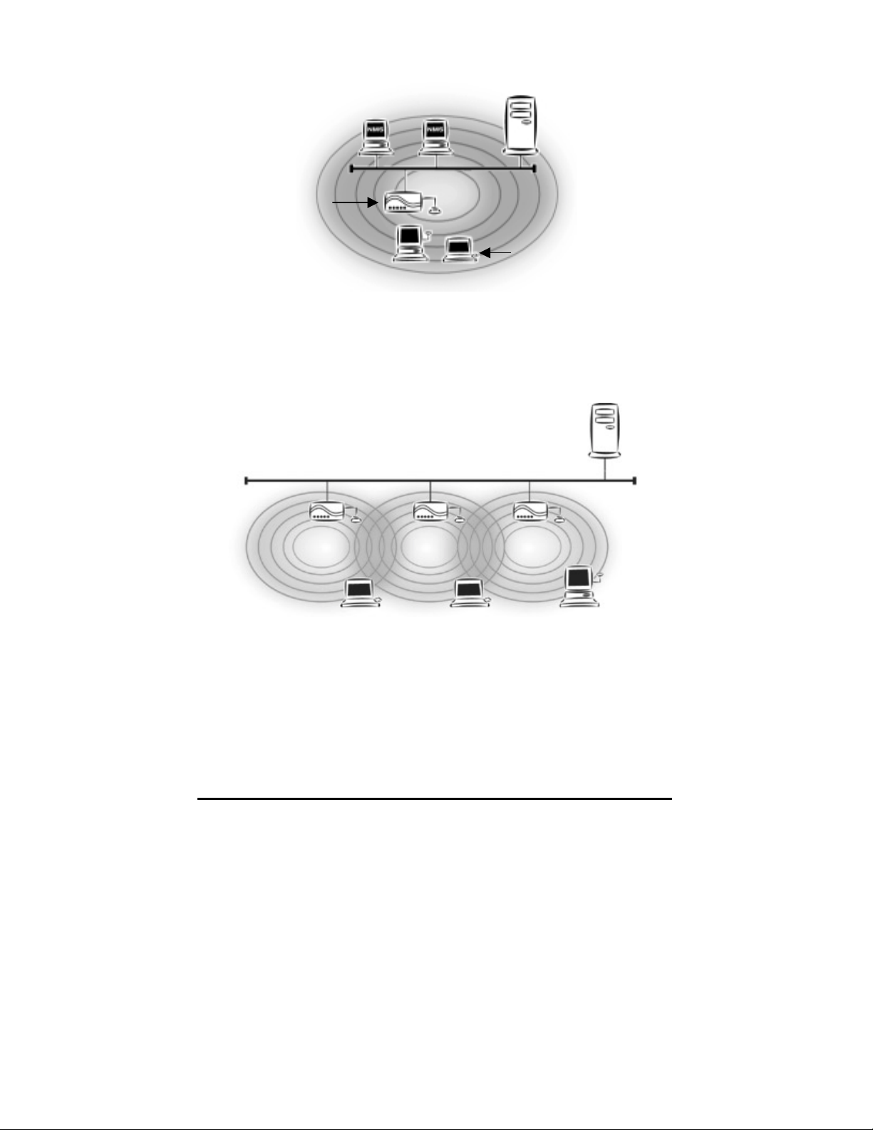
Wired Computers
Server
Access Point
Wireless Computers
Figure 2. Single AP Network
Type 3. The third type of network is composed of multiple APs and multiple
Stations (Figure 3).
Server
“Sales” Domain
Wireless Cell A
AP-1
Station -1
Figure 3. Multiple AP Network
Wireless Cell B
AP-2
Station -2
Wireless Cell C
AP-3
Station -3
The reasons for having multiple APs installed are:
1. To increase bandwidth in order to boost overall network performance
2. To extend the coverage range
Any other type of configuration is usually a mix of these commonly used types.
4 InstantWave High Rate 11Mbps Access Point
Page 11

Planning an Infrastructure Network
This section explains some of the things you need to consider in plannin g an
Infrastructure network. Setting up is a two step process.
1. Install and configure the InstantWave High Rate products
2. Decide the best physical location of the InstantWave High Rate products so as
to optimize performance
The following sections give quick guidelines for these two steps. Before we go
into detail, the network planner should first decide whether to have a single AP
wireless network or a multiple APs network.
Single AP Installation
If you are setting up a simple network with only one AP and a few Stations (a Type
1 or Type 2 network configuration as described in Infrastructure Network, page 3),
the installation can be performed painlessly. All you need to do is make sure the
AP and all the wireless Stations hold the same ‘Domain Name’ in their
configuration.
Adding a new Station to a n existing Infrastructure network is easy. Again, all you
need to do is to set the newly added Station’s ‘Domain Na m e ’ to the same as that
of the AP’s.
Multiple AP Installation
Install multiple APs in the same network (or Domain) with an overlapping signal
(Figure 3
• Use the same Domain Name
• Enable the roaming function in the Station if roaming is required
Note: A Station will automatically connect to whichever AP in the same domain is
)
offering the best signal
InstantWave High Rate 11Mbps Access Point 5
Page 12

Roaming
InstantWave High Rate products are equipped with seamless roaming capabilities.
Roaming is necessary to prevent mobile Stations from being disconnected from the
network as t hey move around.
InstantWave High Rate is designed to allow wireless Stations to roam freely within
an infrastructure domain composed of multiple APs with overlapping signal
coverage (as in the Type-3 network configuration described in the previous
section). For example, roaming enables Station-1 to move from the AP-1 signal
coverage area to the AP-2 signal coverage area without disconnecting from the
network. The handover is achieved transparently; the Station-1 user would not
realize he had moved from AP-1 t o AP-2.
The requirements for a roaming environment are:
a) Multiple APs with overlapping signal coverage (see Multiple AP
Installation, page 5)
b) The APs must be configured to have the same Domain name (see AP
COMFig/Service, page 12)
c) The mobile Stations must have the same Domain name as that of the APs
d) *It is advisable that APs on different TCP/IP subnets be given different
Domain name s t o avoid roaming confus ion (see AP COMFig/Service,
page 12)
Note: *If you want to move your mobile PC between different APs without
terminating the existing networking link, you need to enable the roaming
function on the Mobile Station. The APs that a Mobile Station will roam to
must also be configured with the same domain name. If a Station detects
that the signal quality with the current linked AP is weak, it will search for
an AP in the same domain with a better signal quality and automatically
establish a new connection with it. When a Station is roaming, it will
always use the same IP address. The TCP/IP router will not route
information packets to a Mobile Station if it re-associates with a AP that is
in a different TCP/IP subnet. In other words, if your network consists of two
subnets connected by a router, a Mobile Station may roam to a different
subnet with the same domain name and then fail to communicate with other
network devices via TCP/IP. To avoid ru nning into such an awkward
situation, you must assign different domain names to different TCP/IP
subnets.
6 InstantWave High Rate 11Mbps Access Point
Page 13

Access Point Placement Guidelines
A characteristic of radio communication is the interference problem. Radio is
receptive to interference. Therefore, the more interference you can avoid, the
better performance you will get from wireless products. The follo wing section
describes how the InstantWave High Rate AP should be placed to reduce po ssible
interference.
A few tips to mention that are particularly significant in a radio wave
communications system:
1. Radio waves reflect or refract from buildings, walls, metal furniture, or other
objects. This could result in performance degradation due to the fluctuation of
the received signal.
2. Microwave ovens use the 2.45 GHz frequency band. InstantWave High Rate
also functions in the 2.4 ~ 2.5 GHz band, and therefore shares some of the
band with microwave ovens. This means that when a nearby microwave oven
is in use, it may interfere with InstantWave High Rate, resulting in
performance degradation on the wireless network.
Placing For Performance
For the best performance, it is advisable that users follow the guidelines below in
placing the product:
• Place the AP as high as possible, in as open an area as possible
• Avoid placing the AP close to metal objects (e.g., file cabinets, metal cubicles,
etc.)
• Keep APs and Stations as far away as possible from microwave ovens (10
meters min. is advisabl e)
Placement Tools
InstantWave High Rate includes a Station utility program to help users find the
best location in which to place the AP relative to the location of the Stations.
step1. Allow a wireless Sta tion to connect with the AP
step2. From the Station, run the InstantWave High Rate Statio n Monitor RF
Signal Quality Program
step3. Move the AP and the AP’s antenna to find the best signal quality
InstantWave High Rate 11Mbps Access Point 7
Page 14

Getting Started
Access Point Hardware Installation
Access Point Hardware Setup explains how to quickly setup the Access Point for
use via a wired Ethernet connection, and using the factory default settings. For
installation in networks using other than the default settings, i.e. into existing
networks, complete the Hardware Setup and refer to Using the AP COMFig Tool,
page 11. To setup a wireless station, refer to the PCI/PC Card User’s Guide.
Figure 4. Access Point
step1. Connect the Ethernet network cable to the UTP port on the back panel
of the Access Point.
step2. Connect the power adapter to the electricity outlet and then to the
Access Point DC-In port on the back panel of the access point.
The Access Point is now ready to communicate with the wireless stations using its
factory default settings. Refer to the InstantWave High Rate PCI/PC Card User’s
Guide for card setup instructions.
LED Indicators
The Access Point LEDs show the status of the connections. Figure 5 shows the
LEDs and Figure 6 their functions.
Figure 5. Access Point LEDs
8 InstantWave High Rate 11Mbps Access Point
Page 15

General Color Function
PWR
(Power/Status)
Green
Unlit: Power OFF
Blinking: Diagnostic test
On: Healthy condition
Red
On: Abnormal Condition
E/N (Ethernet) Color Function
TX/RX Orange Blinks to indicate Ethernet
transmission/reception activity
LINK Green Indicates an Ethernet link. If the
radio fails, this LED will not light
RF Color Function
TX/RX Orange Blinks to indicate radio transmission/
reception activity
LINK Green Indicates a wireless link. If the radio
fails, this LED will not light
Figure 6. LED Functions
InstantWave High Rate 11Mbps Access Point 9
Page 16

Hardware Pre-Configuration
Before adding an AP into an existing Ethernet ne twork, you may need to se t basic
configurat i ons, e.g. domain name (SSID), security setting (W EP), AP name,
channel number, or IP address in order to make it compatible with the existing
network.
Follow the steps below to connect the AP to a PC for configuration:
step1. Connect the supplied RS-232 cable to the COM port on the AP and
connect the other end to a serial port (COM port) on the PC
step2. Power on the AP
Installing the AP Management T ools
step1. Insert the InstantWave High Rate CD into the CD-ROM drive and click
Start/Run. Type e:/menu.exe (assuming the CD drive is E) and click
OK to open the InstantWave CD main menu
step2. Click Install AP Management Tools to install the AP COMFig Tool,
AP Management System (APMS) and Trap Server utility to your system
10 InstantWave High Rate 11Mbps Access Point
Page 17
Using the AP COMFig T ool
The AP COMFig Tool is a Windows based utility used to configure the AP via a
COM port connection between the AP and a PC.
It provides the following functions:
• Sets AP parameters (e.g., IP address, Domain name (SSID), Security, etc.)
• Diagnoses the AP hardware and shows the diagnostic results
• Upgrades the AP firmware
• Resets the AP Configuration
• Manages the APMS Host table
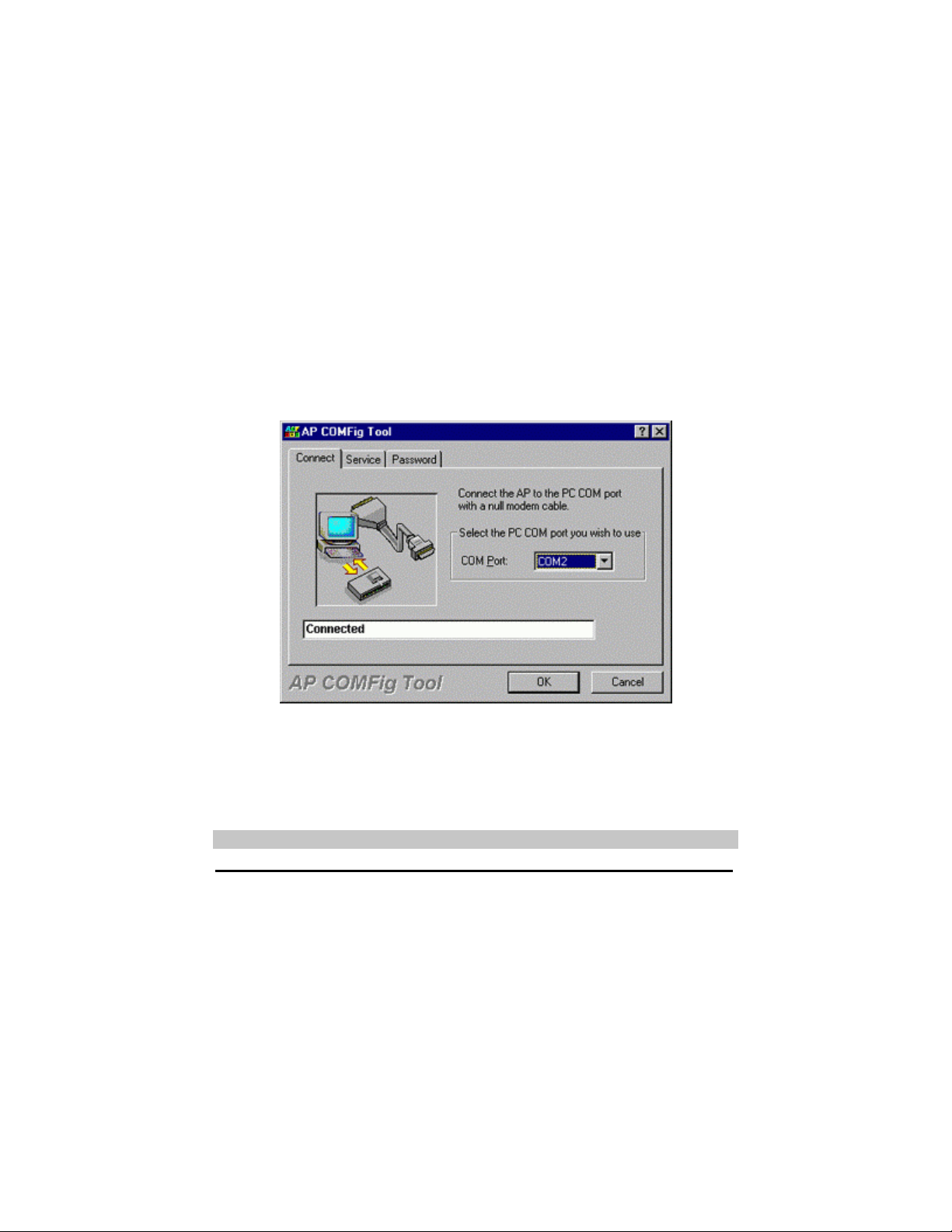
To start the AP COMFIG Tool, click Start/Programs/InstantWave High Rate
AP/AP COMFig Tool. The program opens with the AP COMFig Tool/Connect
card. It will show Connected when a connection is made.
Figure 7. AP COMFig Tool/Connect
AP COMFig/Password
Click on the Password tab to open the Password card. Setting a password prevents
unauthoriz ed changes to the AP configuration settings.
Note: The password will be shared with the APMS program on the same PC.
InstantWave High Rate 11Mbps Access Point 11
Page 18
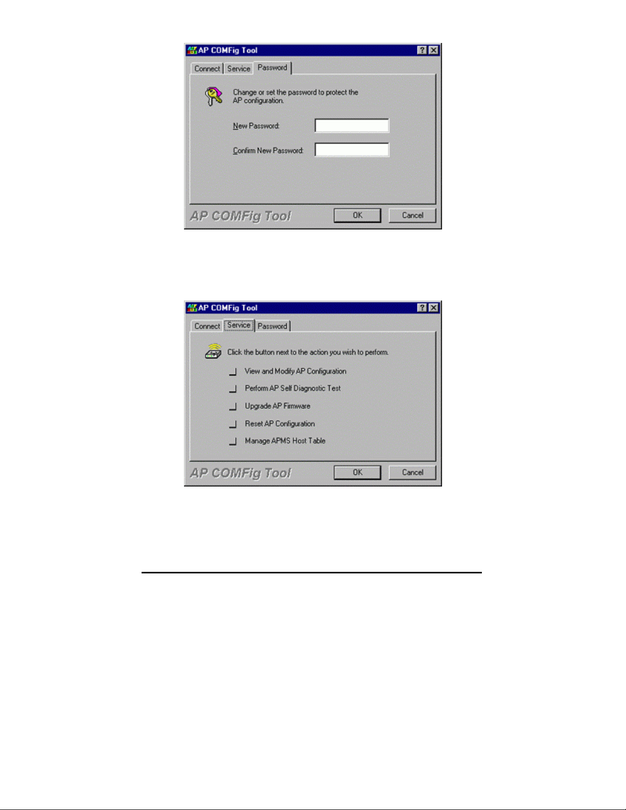
Figure 8. AP COMFig Tool/Password
AP COMFig/Service
After connecting with the AP, click on the Service tab to open the Service card
(Figure 9). The Service card provides access to the management features.
Figure 9. AP COMFig Tool/Service
Click the View and Modify AP Configuration button. The Configuration screen
will open (Figure 10).
12 InstantWave High Rate 11Mbps Access Point
Page 19
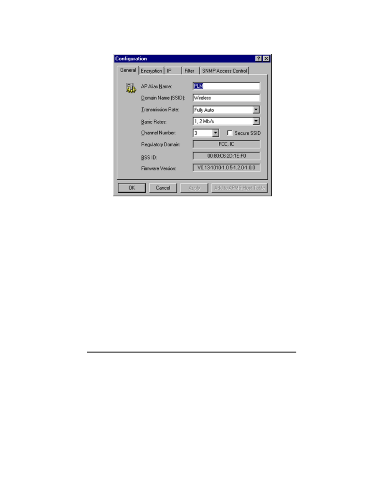
General:
The General card (Figure 10) is the first card in the Configuration section.
Figure 10. Configuration/General
InstantWave High Rate 11Mbps Access Point 13
Page 20

On this card, you can set and view general AP settings:
AP Alias Name
Domain Name
(SSID)
Transmission Rate
Basic Rates
Channel Number
Secure SSID
Assigns the AP a unique human friendly name
that allows the AP to be easily identified
This is commonly called the Domain Name
but is defined in the IEEE 802.11b Wireless
Standard as SSID. Stations and APs in the
same group must use the same Domain Name
Sets the transmission rate at which the data
packets are transmitted by the AP
This value determines the basic rates used and
reported for this BSS by t he AP . The highest
rate specified will be the rate that the AP will
use when transmitting broadcast/multicast and
manageme nt frames.
Available options are:
• 1 and 2Mbps
• All (1, 2, 5.5, and 11Mbps)
You can change the channel number from
here.
Refer to the Appendix, page 52, fo r channels
supported in each regulatory domain
Click to enable or disable the secure SSID
option.
• Blocks a connection request from a
station without the correct SSID
• Hides the SSID in outgoi ng beacon
frames. A sit e-survey tool will not
find the SSID
14 InstantWave High Rate 11Mbps Access Point
Page 21

Regulatory Domain
BSSID
Firmware Version
Important:
In a multiple cell network topology, overlapping and/or adjacent cells using
different channels can operate simultaneously without interference if the frequency
distance between the center frequencies is at least 30MHz. For example channels
1, 7, and 13 are non-overlapping frequency channe ls.
After making any change s, click the Apply button to make the changes effective
immediately, without closing the dialog box, or click OK to accept the changes and
close the box.
Identifies the country where the AP is used.
Each country has defined its available channel
numbers and transmission power (see
Appendix, page 52)
This is the MAC ID of the AP
The current AP firmware version
Encryption:
Data encryption provides more secure wireless data communications. Click the
Encryption tab to setup/change the security settings (Figure 11). The default is
Disabled and initially the keys section will be blank.
InstantWave High Rate 11Mbps Access Point 15
Page 22

Figure 11. Configuration/Encryption
The dropdown Method box lists three options:
1. Disabled (default) - Disable data encryption
2. 40-bit WEP - Enable use of 40-bit WEP
3. 128-bit WEP - Enable use of 128-bit WEP
Key Generation - There are two ways to generate a security key.
The first is by entering any text in the Passphrase field. Click the Generate button.
For 40-bit WEP, it will generate four keys, Key 1, Key 2, Key 3, and Key 4. Select
a key number from the dropdown list of the Default Key box. If you do not
manually select a key, key 1 will be selected. For 128-bit WEP, only one key will
be generated. Click Apply.
Another WEP key generat ion method is to insert the key values directl y from the
keyboard. Enter your own key into one of the Key 1~4 fields. Select that field
number in the Default Key field. If the WEP key is enabled on the AP, all clients
must use the same WEP ke y. Click OK.
Note: Most wireless connection problems arise from improper WEP settings so
make sure all APs and wireless stations use the same settings.
16 InstantWave High Rate 11Mbps Access Point
Page 23

IP:
Note: These SNMP related settings are only useful for network management and
remote configuration (APMS). For proper wireless connections, these
settings don’t have to be changed.
From the IP card (Figure 12) you may view or modify t he Access Point’s TCP/IP
address, configure its subnet mask, or add a default gateway (see the note below).
Note: An AP will directly transfer SNMP respond packets (confirmation packets)
to an APMS PC if it is within the same LAN (the same subnet mask). If an
SNMP respond packet from an AP is destined for an APMS PC on another
LAN, then the SNMP respond packet needs to go through a router-gateway.
The default gateway is the path to that router. If you set the correct default
gateway, then you can use an APMS manager (i.e. a PC running APMS)
physically located in a different subnet to manage this AP.
IP Address
Subnet Mask
Default Gateway
InstantWave High Rate Access Points are delivered with
a default IP of 192.168.1.1
Consult your network administrat or for exact se ttings.
InstantWave High Rate Access Points are delivered with
a default subnet mask of 255.255.255.0
Consult your network administrat or for exact se ttings.
Enter the default gateway address here (if required)
If you wish to change the defaults, set each AP to its new IP address before
introducing it to the open network. All APs within the same network must have
the same TCP/ IP subnet address.
InstantWave High Rate 11Mbps Access Point 17
Page 24

Figure 12. Configuration/IP
After making any change s, click the Apply button to make the changes effective
immediately, without closing the dialog box, or click OK to accept the changes and
close the box.
Note: Click Add to APMS Host Table to add the configured AP to the APMS
Host Table.
18 InstantWave High Rate 11Mbps Access Point
Page 25

Filter:
The next tab on the dialog box is Filter (Figure 13). This is a one-way protocol
filtering mechanism that prevents the AP from transmitting specified protoco ls
from a wired Ethernet LAN into the wireless LAN. If you do not require particular
protocols on the wireless part of your network, you can save bandwidth by
enabling the protocol filter.
Figure 13. Configuration/Filter
From the Filter card, some, all, or none of the protocols listed may be selected for
filtering out:
• IP Protocol
• IPX Protocol
• NetBEUI Protocol
• AppleTalk Protocol
• Other Protocols
• Internet Multicast Frames
After selecting a protocol to be filtered, click the Apply button to make the changes
effective immediately, without closing the dialog box, or click OK to accept the
changes and close the box.
InstantWave High Rate 11Mbps Access Point 19
Page 26

SNMP Access Control:
SNMP Access Control is the next tab on the box (Figure 14).
Figure 14. Configuration/SNMP Access Control
The AP’s access control is managed by a control table on the AP. The first time
this box is opened, the table will be empty. This means that there are no
restrictions on who can access and reconfigure the AP and any user may modify
the AP’s operation. To avoid chaos on the network, access to the AP configuration
should be restricted to only those for whom it is necessary.
Click Add to open the New En try dialog box (Figure 15).
20 InstantWave High Rate 11Mbps Access Point
Page 27

Figure 15. New Entry
Two levels of access are available.
Read Read-only rights. The user may read everything
except the Access Control settings, but cannot
alter anything
Read/Write The user may read and alter all settings
Enter your IP address and then set your own access rights to Read/Write (see the
following note).
Note: Do not set all the stations in the Access Control table to Read. Once this is
set and enabled, it will be difficult to modify the AP. Should this situation
occur, use the AP COMFig utility to reset the configuration.
To set a stations access rights, enter a station’s IP address and community string
(the community string is used as a password to access the AP) and choose Read or
Read/Write.
When all the settings are made, click OK to return to the Access Control card. On
the Access Control card, click the Apply button to make the changes effective
immediately, without closing the dialog box, or click OK to accept the changes and
close the box.
Perform AP Self Diagno stic Test
On the Service card, click Perform AP Self Diagnostic Test. The Hardware
Diagnosis screen will open (Figure 16).
InstantWave High Rate 11Mbps Access Point 21
Page 28

Figure 16. Hardware Diagnosis
Click Start and the tests will commence. As each item is tested, a yellow arrow
will appear alongside it. If the test is successful, the arrow will change to a green
tick. If a failure occurs, an “X” will appear. You can click Cancel at any time to
stop the tests. When the tests have completed, the Cancel button changes to a
Close button. Click Close to return to the Service card.
Upgrade AP Firmware
From time to time updated firmware is released and may be downloaded from our
website at http://www.ndc.com.tw/support/support.htm
The updated firmware may be installed via a COM port using the AP COMFig tool.
Click on Upgrade AP Firmware (Figure 9, page 12). The Upgrade AP Firmware
dialog box will open (Figure 17).
22 InstantWave High Rate 11Mbps Access Point
Page 29

Figure 17. Upgrade AP Firmware
Use the Browse button to choose the file to be uploaded to the AP, or type the file
location and name in the File Name field. The Upload button will then become
enabled. Click Upload. The new firmware will be loaded into the AP’s flash
memory area. When the file transfer is complete, click OK to begin the AP’s
internal firmware updating process.
Reset AP Configuration
Click Reset AP Configuration to open the screen shown in Figure 18, and click
Reset to restore the factory default configuration to the Access Point.
Figure 18. Reset the AP Configuration
Manage APMS Host Table
Click the Manage APMS Host Table button to open the APMS Table dialog box
(Figure 19).
InstantWave High Rate 11Mbps Access Point 23
Page 30

Figure 19. APMS Table-1
From here you can view/delete all the APs added to this host table. This table can
be saved and retrieved from the APMS utility so that you don’t need to create such
a table again in the APMS utility.
Select an AP in the table and click the Details button to view and edit it’s SNMP
access control settings (Figure 20).
Figure 20. APMS Table-2
After making any change s, click OK to return to the Service card.
24 InstantWave High Rate 11Mbps Access Point
Page 31

Using the Access Point Management System (Advanced Configuration and Management)
Once the AP is connected to an Ethernet network, a network administrator can
connect to it from any PC on the same network via the Access Point Management
System (APMS) utility.
The APMS utility is a Windows-based SNMP management tool, allowing network
administrators to remotely configure and monitor APs through an Ethernet or
wireless connection. The APMS mana gement too l is intended for performing fullblown wireless network configuration and management. To launch the APMS
utility, click Start/Programs/InstantWave High Rate AP/AP Management
System.
The progr am opens with the InstantWave Network Mana gement System screen.
You may now configure and monitor t he APs in the wireless network from the
Access Point Host Table.
The APMS Host Table is equivalent to an address book of Access Points (APs).
The first time the program starts the screen will be blank.
Figure 21. Network Management System-1
At least one AP must be entered in the table to allow the local wireless adapter to
connect to it. The next section explains how to add to/edit the Host Table.
Note: Right-clicking anywhere in the main window provides fast access to most of
the main-menu items
To add an AP to the Host Table, use one of the methods below:
1. Load an existing Host Table by clicking Import Host Table from the File
menu. You may load APs you have previ ously conf i gured with the AP
COMFig tool.
InstantWave High Rate 11Mbps Access Point 25
Page 32

Figure 22. Network Management System-2
2. Click the AP main menu item to open its sub-menu and then click Create New
AP (Figure 23).
Figure 23. Network Management System-3
Input the AP’s IP address and its community string (this string will be used for
SNMP access control). When the information has been entered, the OK button will
become active. Click OK. Repeat the process to add more APs. To delete an AP
icon from the window, first select it and then press the Delete key.
Connecting to an AP
Once a Host Table has been created, a connection can be made by double-clicking
an AP’s icon in the Host Table. Alternatively, click AP on the main menu and then
click Connect AP.
In the Connect AP dialog box, click on the down arrow of the AP entry field to
open the dropdown AP list. Select an AP and complete the selection by clicking
OK. If the connection is successful the current connected AP’s IP address will
appear on the title bar.
AP Properties
After connecting, right-clicking on a connected AP’s icon will open a menu. Click
Properties to open the AP Properties screen (Figure 24).
26 InstantWave High Rate 11Mbps Access Point
Page 33

Figure 24. AP Properties
Here you may modify the IP address and Community string. Changes made here
will be immediately effective.
If the connection attempt was unsuccessful, a message box will appear infor ming
you that the request had no response. Click OK to close the message box and
return to the main screen. Go through the procedure again to retry. If you cannot
connect to the AP after three attempts, check that the AP information has been
correctly entered in the Host Table and that the Access Point (AP) is functioning.
Managing Configurations
Config
If the AP selection is successful, the Config and View main menu items will be
enabled. Click the Config main menu item (or right-click on the AP name in the
APMS window) to open a sub-menu.
Figure 25. Config/AP Setting
InstantWave High Rate 11Mbps Access Point 27
Page 34

The menu offers configuration options that enable you to tailor your network to
suit your needs.
• AP Settings - sets the AP’s IP related parameters, sets filters, sets wireless
related parameters, sets AP Access Control list
• Trap Management
• Load Factory Configuration
• Upgrade AP Firmware
• Reset AP
AP Settings
Click AP Settings to open the AP Settings dialog box (Figure 26).
Figure 26. AP Settings/IP
IP:
From the IP card you may view or modify the Access Point’s TCP/IP address,
configure its subnet mask, or add a default gateway (see the following note).
Note: An AP will transfer SNMP respond packets (confirmation packets) to its
APMS PC directly if it is within the same LAN (the same subnet mask). If an
SNMP respond packet from an AP is destined for an APMS PC on another
28 InstantWave High Rate 11Mbps Access Point
Page 35

LAN, then the SNMP respond packet needs to go through a router-gateway.
The default gateway is the path to that router. If you set the correct default
gateway, then you can use a PC running APMS located on a different subnet
to manage this AP.
All InstantWave Access Points are delivered with a default IP of 192.168.1.1 and a
default subnet mask of 255.255.255.0. If you wish to change the defaults, set each
AP to its new IP address before introducing it to the open network.
Consult your network administrat or for exact se ttings.
After making changes, click OK to return to the Config sub-menu and click the
Reset AP menu item to make the changes effective.
Filter:
The second tab on the box is Filter (Figure 27). This is a one-way protocol
filtering mechanism that prevents the AP from transmitting specified protoco ls
from the wired Ethernet LAN into the wireless zone. If you do not require
particular protocols on the wireless part of your network, you can save bandwidth
by enabling the protocol filter.
Figure 27. Filter (APMS)
InstantWave High Rate 11Mbps Access Point 29
Page 36

From the Filter card, some, all, or none of the protocols listed may be selected for
filtering out:
• IP protocol
• IPX protocol
• NetBEUI protocol
• AppleTalk protocol
• Other protocols
• Internet Multicast Frames
Selecting a protocol to be filtered will activate the AP’s protocol filtering
immediately on clicking OK. Clicking Reset AP is not required. If, after filtering a
protocol, your network is not functioning as befo re, it’s likely the protocol is
required on the network and you should disable the filter for that protocol.
TFTP:
The Access Point supports remote firmware upgrades using TFTP (Trivial File
Transfer Protocol). You may customize TFTP services with the following options:
Figure 28. AP Setting/TFTP
30 InstantWave High Rate 11Mbps Access Point
Page 37

Private Transfer:
TFTP currently has no provisions for user authentication. We suggest you keep the
‘Private Transfer’ option checked in order to prevent anyone other than the
network administrator using the APMS program to upgrade the AP firmware. If
you want to use a third party TFTP tool to upgrade the AP firmware, this option
should be disabled.
Timeout:
Specifies the number of seconds TFTP waits to make sure that the sender has
completed the transmission. The range is from 3 to 255 seconds.
SNMP Access Control:
SNMP Access Control is the next tab on the box (Figure 29). SNMP access
control is managed by a control table on the AP.
Figure 29. AP Setting/SNMP Access Control
The first time this box is opened, the table will be empty. This means that there are
no restrictions on who can access and reconfigure the AP and any user may modify
the AP’s operation. Access to the AP configuration should be restricted to only
those for whom it is absolutely necessary. First enter your IP address and then set
your own access rights to Read/Write (see the note below).
InstantWave High Rate 11Mbps Access Point 31
Page 38

Note: Do not set all the stations in the Access Control table to Read. Once this is
set and enabled, it will be difficult to modify the AP. Should this situation
occur, use the AP COMFig utility to re-set the configuration.
Two levels of access are available. To set access rights, enter a station’s IP address
and community string (the community string must be the same as the AP’s in the
Host Table of the APMS manager terminal, i.e. the PC running APMS) and choose
Read or Read/Write.
Read Read-only rights. The user may read everything
except the Access Control settings, but cannot
alter anything
Read/Write The user may read and alter all settings
The Add button will become active. Click Add to add the information to the AP
Access Control table. Click another tab to continue configuration setti ng or click
OK to complete the AP setting. Click the Config/Reset AP menu item to make the
changes effective.
MAC Access Control:
Limit access rights to this Access Point. You may enter up to 1000 stations
(identified by their MAC addresses) into the list.
Figure 30. AP Setting/MAC Access Control
32 InstantWave High Rate 11Mbps Access Point
Page 39

Access Options
MAC Address List:
Status
Disables or enables an individual entry
Address
Comment
Access Options:
Disabled
Accepted List
Denied List
New:
Click New to create a new entry in the MAC Address List.
Delete:
Click Delete to remove a selected MAC address from the list.
Delete All:
Click Delete All to remove all of the MAC addresses from the list.
Import from File:
Click to import a MAC access control table from a file on disk.
Export to File:
Click to export the current MAC access control table to a new file.
The MAC address of a wireless station
A brief description of the wireless station
Stops MAC access control, all wireless stations
are allowed to associate with this access point
The station will be rejected if its MAC address IS
NOT in the list
The station will be rejected if its MAC address IS
in the list
InstantWave High Rate 11Mbps Access Point 33
Page 40

Wireless:
Clicking on the Wireless tab opens the wireless card (Figure 31).
Figure 31. AP Setting/Wireless
34 InstantWave High Rate 11Mbps Access Point
Page 41

The Wireless card groups all the user configurable wireless Access Point (AP)
functions. Here you may make settings as follows:
AP Alias
Name
Domain
Name (SSID)
Secure SSID
Transmission
Rate
Basic Rates
Channel
Number
Regulatory
Domain
Assigns the AP a unique name
This is more commonly called the Domain Name but is
defined in the IEEE 802.11 Wireless Standard as SSID.
Stations and APs in the same group must use the same
Domain Name
• Blocks a connection request without the exact SSID
• Hides the SSID in outgo ing beacon frames. A site
survey tool will not find the AP
The transmission rate at which the data packets are
transmitted by the AP. You can set this to Auto select 1 or
2Mbps, Fixed 1Mbps, Fixed 2Mbps, Fixed 5.5Mbps, Fixed
11Mbps or Full Auto (1 to 11Mbps)
This value determines the basic rates used and reported for
this BSS by the AP. The highest rate specified will be the
rate that the AP will use wh e n transmitting
broadca st/ mult i ca st a nd management fra me s.
Available options are: 1 and 2Mbps and All (1, 2, 5.5, and
11Mbps)
Refer to the Appendix, page 52, for a list of the channels
supported in each regulatory domain
Identifies the country where the AP is used (see the
Appendix, page 52). Each Regulatory Domain has defined
the channel numbers and transmission power available
After making any change s, click OK and then click the Reset AP menu item.
InstantWave High Rate 11Mbps Access Point 35
Page 42

Encryption:
Note: Most wireless connection problems arise from improper WEP settings so
make sure all APs and wireless stations use the same settings.
Sets the data encryption parameters for the wireless LAN.
Click the arrow to the right of the Method box. The dropdown list has three
options:
Figure 32. AP Setting/Encryption
Disabled (default)
Stations communicate with this Access Point without any data encryption.
40-bit WEP
Stations communicate with this Access Point via 40-bit WEP data encryption.
128-bit WEP
Stations communicate with this Access Point via 128-bit WEP data encryption.
In order to decode the data transmissions, each wireless client on the network must
use identical keys.
Key Generation - There are two ways of generating a security key.
36 InstantWave High Rate 11Mbps Access Point
Page 43

The first is by entering any text in the Passphrase field. Click the Generate button.
For 40-bit WEP, it will generate four keys, Key 1, Key 2, Key 3, and Key 4. Select
a key number from the dropdown list of the Default Key box. If you do not select a
key, key 1 is selected, as it is the default key. For 128-bit WEP, only one key is
generated. Click OK.
Another WEP key generat ion method is to insert the key values directl y from the
keyboard. Enter your own key into one of the Key 1~4 fields. Select that field
number in the Default Key field. If the WEP key is enabled on the AP, all clients
must use the same WEP ke y. Click OK.
Trap Management
Trap Management allows you to setup the configuration of the Trap Server
program. When an AP is powered on, or its Ethernet port becomes active, the AP
will send messages to the assigned trap server to report these activities.
To assign a trap server, click Trap Management (Figure 33). Assign a station as a
trap server by entering its IP address and network port type. Click Add.
To remove a trap server from the list, highlight it and click Delete. Click Delete
All to remove all assigned trap servers from the list.
Figure 33. Trap Management
To view trap log information, click Start/Programs/InstantWave High Rate
AP/Trap Server to open the following screen.
InstantWave High Rate 11Mbps Access Point 37
Page 44

Figure 34. AP Trap Server Program
When the AP is powered on, or an Ethernet port becomes active, an event log will
be generated indicating the time, the MAC ID of the reporting AP, and the activity.
You may save, open, and delete log files from the File menu.
In the Program menu, select Auto Startup After Reboot to activate the Trap Server
when the system is rebooted, or Pause Program to pause the Trap Server.
Load Factory Configuration
Clicking Load Factory Configuration opens a dialog box. Click OK to
return the AP to the default settings. The default IP setting is 192.168.1.1
and the default subnet mask is 255.255.255.0. Click the Reset AP menu
item to make the changes effective.
Upgrade AP Firmware
The Access Point’s (AP’s) embedded software is b urned into the flash ROM.
However, an updated AP code can be installed over your LAN via the APMS
program. Click on Upgrade AP Firmware. The Upgrade AP Firmware dialog
box will open (Figure 35).
Use the Browse button to choose the file to be uploaded to the AP, or type the file
name and path in the Local File field.
38 InstantWave High Rate 11Mbps Access Point
Page 45

Figure 35. Upgrade AP Firmware
The Upload button will then become enabled. Click Upload to start uploading the
file to the Access Point. The APMS and the AP’s built-in Trivial File Transfer
Protocol (TFTP) command will upload the new executable into the AP’s flash
memory area. If the upload activity fails, an error message will be shown on the
message box.
Resetting the AP will take about 30 seconds. During this time, the APMS program
will not be able to query the AP via the SNMP protocol and the AP will not be
available to other stations. If you try to access it, the APMS program will display a
“No response fro m the AP ” me ssa ge.
When the file transfer is complete, click OK to close the window.
Reset AP
After changing the AP’s IP, Access Control, or Wireless options, the AP needs to
be reset to enable the new settings. Prior to exiting the APMS program, or
selecting a different AP, click the Reset AP menu item. A confirmation window
will open. Click OK to reset the AP or Cancel to abort the reset command.
InstantWave High Rate 11Mbps Access Point 39
Page 46

Viewing InstantWave High Rate Information and Statistics
View
The menu items under View provide read-only information and statistics. To
customize the screen view, right-click in the main screen to open a context
sensitive menu. Select your preferred view, i.e. Icons, List, Details, etc.
Figure 36. View Menu
The Status bar at the bottom of the screen shows the connecting status. When the
bar shows Ready, Associated will appear on the bar along with the IP address of
the associated AP.
AP Information
Clicking AP Information opens a window displa ying the AP’s system information
(Figure 37). The information shown is read-only.
40 InstantWave High Rate 11Mbps Access Point
Page 47

Figure 37. AP Information
When finished viewing AP information, click OK to close the window.
Wireless Stations
The Connected Wireless Stations window lists all the currently associated wireless
station’s Media Access Control (MAC) addresses. When finished viewing, click
OK to close the window.
Statistics
Clicking statistics opens a sub-menu with two options: Wireless Port and Ethernet
Port. A list of Tx and Rx statistics data follows.
InstantWave High Rate 11Mbps Access Point 41
Page 48

Figure 38. Wireless Port Statistics
Figure 39. Ethernet Port Statistics
These statistics will be lost when the Access Po int (AP) reboots or is reset. To poll
for new statistics click on the Polling Timer button. Set the time period (in
seconds) and click OK to close the box. Click Update to start the polling sequence.
The statistics shown may be saved to a file or p rinted. Click OK to return to the
main menu.
Saving the AP’s Configuration to a File
After the targeted AP has connected successfully, the AP’s configuration can be
saved as a WLN file in text format. To do this, first click on the File main menu
item. From the sub-menu click Save AP Configuration. A standard Windows
Save As dialog box will appear. Enter a file name, choose a location for the file,
and click OK.
42 InstantWave High Rate 11Mbps Access Point
Page 49

Figure 40. Save AP Configuration
Loading the AP’s Configuration from a File
To load a configuration file (.WLN) to the Access Point, on the File menu, click
Load AP Configuration. Select a configuration file and open it. The following
dialog box will open and display the detailed settings.
Figure 41. Load Configuration
Include IP address settings: If you want to include the IP settings, check
this option (overwrites the AP’s current IP settings).
Encryption
The configuration file does not cont ain the security key settings. The
InstantWave High Rate 11Mbps Access Point 43
Page 50

attributes of security keys are externally write-only and cannot be saved
into the configuration file. Click Encryption to setup the securit y keys
manually.
Password
Clicking Password opens a Change Password configuration box. Enter your new
password and then enter it again to confirm. Click OK to close the box. Once a
password is set you will be asked for it each time the APMS program is opened.
Note: The password is shared between the APMS and the AP COMFig program
on the same PC.
44 InstantWave High Rate 11Mbps Access Point
Page 51

T roubleshooting
f
This section provides you with some tr oubleshoo t ing info should you encounter
installation or operation proble ms on InstantWave High Rate products. If the
problems still cannot be remedied after going through the Troubleshooting section,
check the FAQs at http://www.ndc.com.tw/support/tech/iw_faq.htm
If you still have a problem, contact NDC technical support for assistance (see
Technical Support, page 47).
Before going through the following troubleshooting information, run the AP Self
Diagnostic Test to ensure the major AP components are working.
If your problems still cannot be remedied after going through this Troubleshooting
section, contact NDC technical support for assistance (see Technical Support, page
47).
Symptom Suggested Solutions
The Power LED on the
AP is OFF.
The InstantWave HR
APMS utility cannot
detect an InstantWave
HR AP on the same
network.
The AP powers up, but
the Ethernet Link LED is
OFF (no connection to
an Ethernet network).
The Status LED on the
AP panel is Red and
lashing.
1. Make sure the power adapter is firmly connected to
the power outlet and the AP power connector.
1. Make sure the AP is powered on and connected to
an Ethernet work.
Check the IP addresses assigned to the AP and APMS
terminal PC. They should be in the same subnet and
unique. For example, if the AP’s IP address is
192.168.1.5 with a mask of 255.255.255.0, then the
PC’s IP address should be 192.168.1.x with a mask of
255.255.255.0. Consult your network administrator
for exact settings.
Make sure:
1. The Ethernet cable is connected firmly to both the
AP and Hub/Switch.
3. The Hub/Switch is powered on.
4. Your Hub/Switch port may be set to the “Uplink”
position. Set it to the normal position.
Restart (power cycle) the AP and check the Status
LED again. If it is still flashing, you need to return the
AP to the reseller for repair.
InstantWave High Rate 11Mbps Access Point 45
Page 52

A wireless PC cannot
associate with the AP,
even though the link
quality is perfect and the
taskbar indicator is
green.
Transmission
performance is slow or
erratic.
The AP and wireless
adapter are working, but
the PC cannot connect
to the Ethernet network
via the AP.
The AP cannot be
detected by the Site
Survey tool
Make sure your wireless PC is using a WiFi compliant
adapter and has the same SSID and security settings as
the AP.
1. SSID:
The ‘Domain Name (SSID)’ is case-sensitive and must
be the same as that of the AP. See Figure 10, page 13
(AP COMFig) or Figure 31, page 34 (APMS).
2. Security:
You need to have the same security setting (Disabled,
40-bit WEP, or 128-bit WEP) and WEP key (if 40-bit
or 128-bit WEP is selected). See Encryption, page 15
(AP COMFig) or page 36 (APMS).
1. Move your wireless PC closer to the AP to find a
better signal. If the signal is still weak, change the
direction of the antenna slightly.
2. There may be interference, possibly caused by a
microwave oven, 2.4GHz wireless phone, or metal
objects. Move these interference sources or
change the location of the wireless PC or AP.
3. Change the wireless channel on the AP. See
Figure 10, page 13 (AP COMFig) or Figure 31,
page 34 (APMS).
4. Check the AP antenna, connectors, and cabling are
firmly connected.
1. The MAC access control function is enabled and
this PC is denied access. See Figure 30, page 32.
2. The Protocol Filter has blocked required protocols,
e.g. TCP/IP to the PC. Uncheck these protocols
from the filtering list. See Figure 13, page 19 (AP
COMFig) or Figure 27, page 29 (APMS).
3. The IP settings on the PC are not correct.
1. The distance between the AP and wireless PC is
too great.
2. The Secure SSID setting has been set. See Figure
10, page 13 (AP COMFig) or Figure 31, page 34
(APMS).
46 InstantWave High Rate 11Mbps Access Point
Page 53

T echnical Sup port
Support from Your Network Supplier
If assistance is required, call your supplier for help. Have the following
information ready before you make the call.
1. LED status
2. A list of the product hardware (including revision le vels), and a brief
description of the network structure
3. Details of recent configuration changes, if applicable
Support from NDC
If you have any problems t hat you canno t resolve with the information in
troubleshooting, or the FAQs at
http://www.ndc.com.tw/support/tech/iw_faq.htm
please note the following information and contact our technical support team:
• What you were doing when the error occurred
• What error messages you saw
• Whether the problem can be reproduced
• The serial number of the product
• The firmware version and the debug information
NDC Technical Support is available via:
E-mail: techsupt@ndc.com.tw
For other information about NDC, please visit us at: www.ndc.com.tw
InstantWave High Rate 11Mbps Access Point 47
Page 54

NDC Limited Warranty
Hardware
NDC warrants its products to be free of defects in workmanship and materials,
under normal use and service, for a period of 12 months from the date of purchase
from NDC or its Authorized Reseller, and for the period of time specified in the
documentation supplied with each product.
Should a product fail to be in good working order during the applicable warranty
period, NDC will, at its option and expense, repair or replace it, or deliver to the
purchaser an equivalent product or part at no additional charge except as set forth
below. Repair parts and replacement products are furnished on an exchange basis
and will be either reconditioned or new. All replaced products and parts will
become the property of NDC. Any replaced or repaired product or part has a
ninety (90) day warranty or the remainder of the initial warranty period, whichever
is longer.
NDC shall not be liable under this warranty if its testing and examination disclose
that the alleged defect in the product does not exist or was caused by the
purchaser’s, or any third party’s misuse, neglect, improper installation or testing,
unauthorized attempt to repair or modify, or any other cause beyond the range of
the intended use, or by accident, fire, lightning, or other hazard.
Software
Software and documentation materials are supplied “as is” witho ut warranty as to
their performance, merchantability, or fitness for any particular purpose. However,
the media containing the software is covered by a 90-day warranty that protects the
purchaser against failure within that period.
Limited Warranty Service Procedures
Any product (1) received in error, (2) in a defective or non-functioning condition,
or (3) exhib iting a defect under normal working conditions, can be re turned to
NDC by following these steps:
You must prepare:
Dated proof of purchase
Product model number & quantity
Product serial number
Precise reason for return
Your name/address/email address/telephone/ fax
1. Inform the distributor or retailer.
2. Ship the product back to the distributor/retailer with prepaid freight. The
purchaser must pay the shipping fee from the distributor/retailer to NDC. Any
package sent C.O.D. (Cash On Delivery) will be refused.
48 InstantWave High Rate 11Mbps Access Point
Page 55

3. Charges: Usually RMA (Returned Material Authorization) items will be
returned to the purchaser via airmail, prepaid by NDC. If returned by another
carrier, the purchaser will pay the difference. A return freight and handling
fee will be charged to the purchaser if NDC determines that there was “No
Problem Found” or that the damage was caused by the user.
Warning
NDC is not responsible for the integrity of any data on storage equipment (hard
drives, tape drives, floppy diskettes, etc.). We strongly recommend that our
customers back their data up before sending such equipment in for diagnosis or
repair.
Services after Warranty Period
After the warranty period expires, all products can be repaired for a reasonable
service charge. The shipping charges to and from the NDC facility will be borne
by the purchaser.
Return for Credit
In the case of a DOA (Dead on Arrival) or a shipping error, a return for credit will
automatically be applied to the purchaser’s account, unless o therwise requested.
Limitation of Liability
All expressed and implied warranties of a product’s merchantability, or of its
fitness for a particular purpose, are limited in duration to the applicable period as
set forth in this limited warranty, and no warranty will be considered valid after its
expiration date.
If this product does not fu nction as warranted, your sole remedy shall be repair or
replacement as provided for above. In no case shall NDC be liable for any
incidental, consequential, special, or indirect damages resulting from loss of data,
loss of profits, or loss of use, even if NDC or an authorized NDC distributor/dealer
has been advised of the possibility of such damages, or for any claim by any other
party.
InstantWave High Rate 11Mbps Access Point 49
Page 56

Specifications
General
Regulatory
Compliance
Standards
Data Rate
Communication
Method
Security
LED Indicators
Interfaces/Connectors
Power
Dimensions
Wireless Specifications
Emission Type
RF Frequency Range
Transmitter
Antenna Type
FCC Part 15 Class B. (US)
Wireless LAN: IEEE 802.11b, Wi-Fi Compliant
Ethernet: IEEE 802.3
11Mbps/5.5Mbps/2 Mbps/1Mbps auto fallback
Half-Duplex
40-bit/128-bit WEP Data Encryption
Power, Ethernet Activity, Ethernet Link, Wireless Activity,
Wireless Link
10Base-T: RJ-45
RS-232C: V.24 compliance. D-SUB 9 pin
Power Voltage: DC 5.1Volt ± 5 %
AC Adapter: AC 100V~240V
Power Consumption: 5.1Volt, 1.0 A (Typical)
138 x 114 x 37mm (5.43 x 4.49 x 1.46in)
Direct Sequence Spread Spectrum
2471MHz ~ 2497MHz – Japan Band
2400MHz ~ 2483.5MHz – North America, Europe, and
Extended Japan Band
2445MHz ~ 2475MHz – Spain
2446.5MHz ~ 2483.5MHz – France
RF Output Power: 20 dBm
Frequency Stability: Within ± 25ppm
Data Modulation Type:
BPSK (1Mbps)/QPSK (2/5.5/11Mbps)
Data Modulation Speed:
11Mbps/5.5Mbps/2Mbps/1Mbps with Auto Fallback
Dual Dipole Diversity Antenna
50 InstantWave High Rate 11Mbps Access Point
Page 57

Software
SNMP Functions
Security
Firmware Upgrade
Environment
Temperature
Humidity
Configuration via COM port
and
Configuration and management via SNMP in a Windows
environment through Ethernet.
MIB II (RFC 1213), Bridge MIB (RFC 1493) Enterprise
MIB
Trap Filter
Data encryption
Access control
Password assignment and rights
Access Point firmware upgrade via COM port, Ethernet,
wireless, or PPP connection from remote site
Operating: 0°C ~ +50°C (Except RF output power and
sensitivity)
Storage: -30°C ~ +70°C
85% at 40°C
InstantWave High Rate 11Mbps Access Point 51
Page 58

Appendix
F
This appendix lists the channels supported by the world’s regulatory domains.
The channel numbers, channel center frequencies, and regulatory domains are
shown in the table.
Channel
Number
1 2412 O O O
2 2417 O O O
3 2422 O O O
4 2427 O O O
5 2432 O O O
6 2437 O O O
7 2442 O O O
8 2447 O O O
9 2452 O O O
10 2457 O O O O O
11 2462 O O O O O
12 2467 O O O
13 2472 O O O
14 2484 O
Center
requency
(MHz)
FCC/
Canada
ETSI Spain France Japan
52 InstantWave High Rate 11Mbps Access Point
Page 59

EC DECLARATION OF CONFORMITY
For the following equipment:
Product Name : InstantWave Wireless Access Point
Model Number : NWH650
is hereby confirmed to comply with the requirements set out in the Council
Directive on the Approximation of the Laws of the Member States relating
to R&TTE Directive(99/ 5/ EC). For the evaluation regarding the
electromagnetic compatibility, the following standards were applied.
The product meets or exceeds the following EMC standards:
EN 300 328 (November 1996/A1 (July 1997))
EN 300 826 (November 1997)
En 60950:1992 + A1:1993 + A2:1993 + A3:1995 + A4:1996 + A11:1997
The manufacturer/importer is responsible for this declaration:
Company Name : NDC Europe
Company Address : 1, Earlsfort Centre
Hatch Street
Dublin 2, Ireland
Person authorized to mak e this declarat ion :
Name : Changhua Chiang
Position/Title : President & CEO
November 15, 2001
Date Legal Signature
InstantWave High Rate 11Mbps Access Point 53
Page 60

Index
A
Accepted List................................33
Access Control........................20, 31
Access Options.............................33
Access Rights .........................20, 31
Alias Name.............................14, 35
AP COMFig
Password...................................11
Service......................................12
AP COMFig Tool
Using.........................................11
AP Configuration
Load..........................................43
Save ..........................................42
AP Information.............................40
AP Properties................................26
AP Settings...................................28
APMS Host Table.........................23
B
Basic Rates .............................14, 35
BSSID ........................................... 15
C
Cabling ...........................................1
Channel Number ..................... 14, 35
Channels
Non-overlapping.......................15
Connecting to an AP..................... 26
D
Default Gateway..................... 17, 28
Default IP................................17, 29
Default Settings ............................38
Default Subnet Mask ..............17, 29
Denied List ...................................33
Domain Name......................... 14, 35
E
Encryption ........................ 15, 36, 43
54 InstantWave High Rate 11Mbps Access Point
Export MAC Access Control Table
...................................................33
F
Filter Protocols........................19, 29
Firmware Version .........................15
Flash ROM....................................22
G
General..........................................13
H
Host Table.....................................23
I
Import MAC Access Control Table
...................................................33
Information, AP ............................40
L
LEDs...............................................8
Load AP Configuration.................43
Load Factory Configuration..........38
M
MAC Access Control....................32
MAC Address ...............................41
MAC Address List........................33
Modify AP Configuration .............12
N
Network
Infrastructure...............................3
Multiple APs...............................4
P
Packing List................................... iii
Password/AP COMFig..................11
Placement Guidelines......................7
Placing
for performance...........................7
Tools ...........................................7
Page 61

Polling Timer................................42
Properties......................................26
Protocol Filtering....................19, 29
R
Regulatory Domains............... 15, 35
Reset AP Configuration................23
Resetting the AP...........................39
S
Save AP Configuration.................42
Secure SSID............................ 14, 35
Self Diagnostic Test......................21
Service Set ID.........................14, 35
Service/AP COMFig.....................12
SNMP ...........................................39
SNMP Access Control............20, 31
Statistics
Ethernet Port.............................41
Wireless Port.............................41
Subnet Mask...........................17, 28
System Requirements.....................1
T
TCP/IP Address.......................17, 28
Transmission Rate...................14, 35
Trap Log Information....................37
Trap Management.........................37
Trap Server....................................37
Troubleshooting............................45
U
Upgrade AP Firmware (AP COMFig
Program)....................................22
Upgrade AP Firmware (APMS
Program)....................................38
V
View Info. & Statistics..................40
View/Modify AP Configuration....12
W
Wireless Stations...........................41
55 InstantWave High Rate 11Mbps Access Point
 Loading...