

Page 1
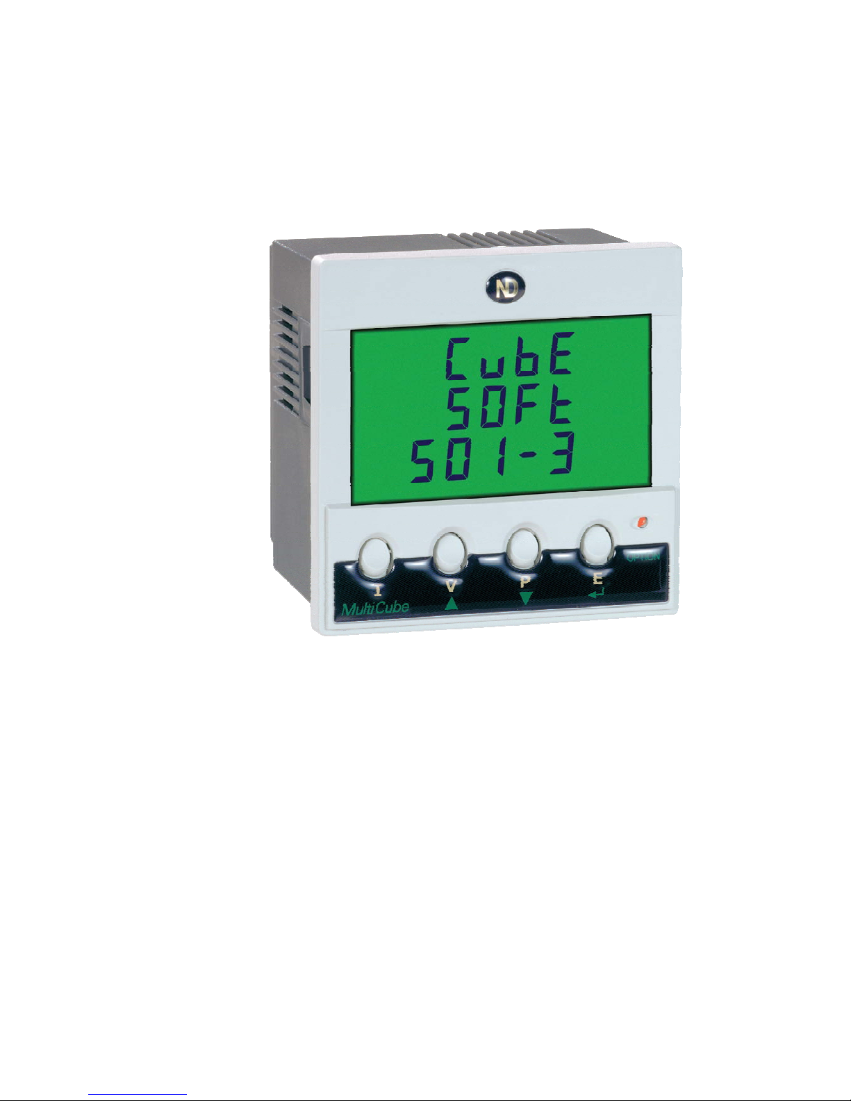
MultiCube
Single Phase
Multi-Function Electricity Meter
Installation and Operation
Page 2

Page 3

PREFACE
MultiCube Single Phase Meter
Operating Guide Revision 5.02
December 2004
This manual represents your meter as manufactured at the time of publication. It
assumes standard software. Special versions of software may be fitted, in which
case you will be provided with additional details.
Every effort has been made to ensure that the information in this manual is complete
and accurate. We revised this manual but cannot be held responsible for errors or
omissions.
The apparatus has been designed and tested in accordance with EN 61010-1, ‘Safety
Requirements for Electrical Equipment for Measurement, Control and Laboratory
Use’. This operating guide contains information and warnings which must be
followed by the user to ensure safe operation and to maintain the apparatus in a safe
condition.
We reserve the right to make changes and improvements to the product without
obligation to incorporate these changes and improvements into units previously
shipped.
General Editor : Ian Sykes BSc (hons).
Copyright © 2004 : Northern Design (Electronics) Ltd,
228 Bolton Road, Bradford. West Yorkshire. UK.
Page 4

Table Of Contents
1. SAFETY....................................................................................................................................................... 5
1.1 W
ARNING SYMBOLS
....................................................................................................................................... 5
1.2 M
AINTENANCE
............................................................................................................................................... 5
2. METER OPERATION.................................................................................................................................. 6
2.1 M
EASUREMENTS
............................................................................................................................................ 6
2.1.1 Rolling Demand (I kW, kVA and kvar Demands) .............................................................................. 6
2.2 P
OWER UP
.................................................................................................................................................... 8
2.3 D
ISPLAY PAGES
............................................................................................................................................. 8
AMPS & PEAK AMPS........................................................................................................................................... 9
VOLTS & PEAK VOLTS ....................................................................................................................................... 9
2.4 D
ISPLAY SCALING
........................................................................................................................................ 13
2.4.1 Voltage Scaling (Phase, Peak)........................................................................................................ 13
2.4.2 Current Scaling (Phase, Peak, In, MD, Pk MD)............................................................................... 13
2.4.3 Per Phase & System Power Scaling (W, VA, var)........................................................................... 14
2.4.4 Energy Registers (Wh, VAh, varh) .................................................................................................. 14
2.4.5 Miscellaneous (Frequency, PF, THD) ............................................................................................. 14
2.5 E
NERGY REGISTER RESET
........................................................................................................................... 15
2.6 P
EAK VOLTAGE RESET
................................................................................................................................. 15
2.7 P
EAK CURRENT RESET
................................................................................................................................15
2.8 P
EAK DEMAND RESET
.................................................................................................................................. 15
2.9 I
SOLATED PULSE OUTPUTS
........................................................................................................................... 16
3. INSTALLATION......................................................................................................................................... 17
3.1 P
ANEL MOUNTING
........................................................................................................................................ 17
3.2 CT C
ONNECTIONS
....................................................................................................................................... 18
3.3 V
OLTAGE CONNECTIONS
.............................................................................................................................. 18
3.4 A
UXILIARY MAINS SUPPLY
(L & N)................................................................................................................ 19
3.5 C
ONNECTION SCHEMATICS
........................................................................................................................... 20
4. PROGRAMMING....................................................................................................................................... 21
4.1 D
ESCRIPTION
............................................................................................................................................... 21
4.2 E
NTERING AND EXITING PROGRAMMING MODE
.............................................................................................. 21
4.3 S
ETTING THE
CT P
RIMARY CURRENT
........................................................................................................... 22
4.4 S
ETTING THE
PT P
RIMARY VOLTAGE
............................................................................................................ 23
4.5 S
ETTING PULSE OUTPUT
1 R
ATE
.................................................................................................................. 24
4.6 S
ETTING PULSE OUTPUT
2 R
ATE
.................................................................................................................. 25
4.7 S
ETTING THE AMPERE DEMAND PERIOD
....................................................................................................... 26
4.8 S
ETTING THE K
W R
OLLING AVERAGE PERIOD
............................................................................................... 27
5. SPECIFICATION ....................................................................................................................................... 28
Page 5
Meter Operation
Single Phase MultiCube Page 5
1. Safety
1.1 Warning Symbols
This manual provides details of safe installation and operation of the meter. Safety
may be impaired if the instructions are not followed. Labels on individual meters give
details of equipment ratings for safe operation. Take time to examine all labels on the
meter and to read this manual before commencing installation.
CAUTION WARNING
Refer to Operating Manual Danger Risk of Electric Shock
Figure 1-1 Safety Symbols
WARNING
The meter contains no user serviceable parts. Installation and
commissioning should be carried out by qualified personnel
1.2 Maintenance
The equipment should be maintained in good working order. Damage to the product
should be repaired by the manufacturer. The meter may be cleaned by wiping lightly
with a soft cloth. No solvents or cleaning agents should be used. All inputs and
supplies must be isolated before cleaning any part of the equipment.
Page 6

Meter Operation
Page 6 Single Phase MultiCube
2. Meter Operation
2.1 Measurements
The MultiCube makes use of a high speed micro-processor and an Analogue to
Digital converter to monitor input signals. The phase voltage, current and power (kW)
are measured directly and a number of other parameters derived from these in
software. The measurement process is continuous with all signals scanned
simultaneously at high speed ensuring that all input cycles are detected. Distorted
input waveforms, with harmonics to the 20th are therefore detected accurately.
Derived parameters are calculated and displayed once a second, scaled by user
programmed constants for current and voltage transformers.
Instantaneous power parameters are integrated over long time periods providing a
number of energy registers. System frequency is detected by digital processing of
the voltage input signal.
2.1.1 Rolling Demand (Amps and kW Demands)
Average values of Amps and kW are calculated over a user programmable time
period (10 - 2500 seconds for Amps, 1 - 60 minutes for kW). The displays show the
averages for the most recent time period ending at the time the display was last
updated. The demand period is continuously updated as time progresses hence the
term “Rolling Demand”.
2.1.1.1 Calculating Rolling Demand
Each user set time period is split into smaller sub-periods (10 for Amps, 15 for kW).
An average value for measurements taken every second during a sub-period are
calculated for each parameter. The most recent 10 (15 for kW) sub-period averages
are stored in memory as an array. An average of the data in each of these arrays is
displayed as MD (rolling demand).
Page 7

Meter Operation
Single Phase MultiCube Page 7
On power up (or after a brown-out) the sub-period array values are reset to zero.
During the first full MD period the Rolling Demand value will accumulate as the
zeroes are replaced with valid sub-period averages.
2.1.1.2 Peak Demand (kW and I Pk Demand)
Peak MD readings are the maximum recorded values of corresponding Rolling
Demand values.
These may be used to determine the maximum load requirement of a system. They
are often used to determine spare capacity in a supply system, supply plant
requirement etc.
On power failure or brown-out Peak Demand values are automatically saved in nonvolatile memory within the MultiCube. The memory requires no battery and will hold
the value for up to 10 years in the absence of mains power.
Page 8

Meter Operation
Page 8 Single Phase MultiCube
2.1.1.3 Meter Types
Five Single Phase MultiCube meter types are available to suit a range of applications.
The meter type defines a number of display pages which may be selected and the
parameters metered. This manual covers all meters independent of type.
2.2 Power Up
On power up the MultiCube shows the meter type and software issue. The example
below shows software issue 5.01 meter type 3
CubE
SOFt
501-3
2.3 Display Pages
To select current measurements press the I key repeatedly until the desired page is
displayed. The number of pages available is dependant on meter type.
To select voltage measurement press the
V
key until the desired page is displayed.
Only a single page is available for voltage measurement on all meter types.
To select power measurements press the
P
key repeatedly until the desired page is
displayed. The number of pages available is dependant on meter type.
To select energy measurements press the
E
key repeatedly until the desired page is
displayed. The number of pages available is dependant on meter type.
Display pages available on the full range of Single Phase MultiCube meters are
shown below followed by tables showing those available on each standard meter
type.
Page 9
Meter Operation
Single Phase MultiCube Page 9
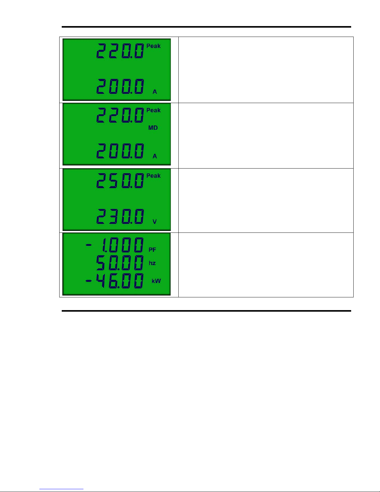
Amps & Peak Amps
Instantaneous true rms. Current scaled by the user
programmable CT primary is updated each second on
the bottom line.
The largest measured instantaneous value (peak) is
shown on the top
Ampere Demand
MD based on a rolling average calculation of Amps
with a user programmable period 10s to 2500s
An average display based on 10 sub-period values
(1s to 250s) is updated at the end of each sub period
on the bottom line. The largest recorded value of this
is displayed on the top line as Peak.
Volts & Peak Volts
Instantaneous true rms. Volts scaled by the user
programmable PT primary is updated each second on
the bottom line.
The largest measured instantaneous value (peak) is
shown on the top line.
PF, Hz, W
Power Factor (‘-’ denotes capacitive).
Frequency detected on voltage input signal.
Instantaneous Watts scaled by the user
programmable CT and PT primaries (‘-’ denotes
Export).
Page 10
Meter Operation
Page 10 Single Phase MultiCube
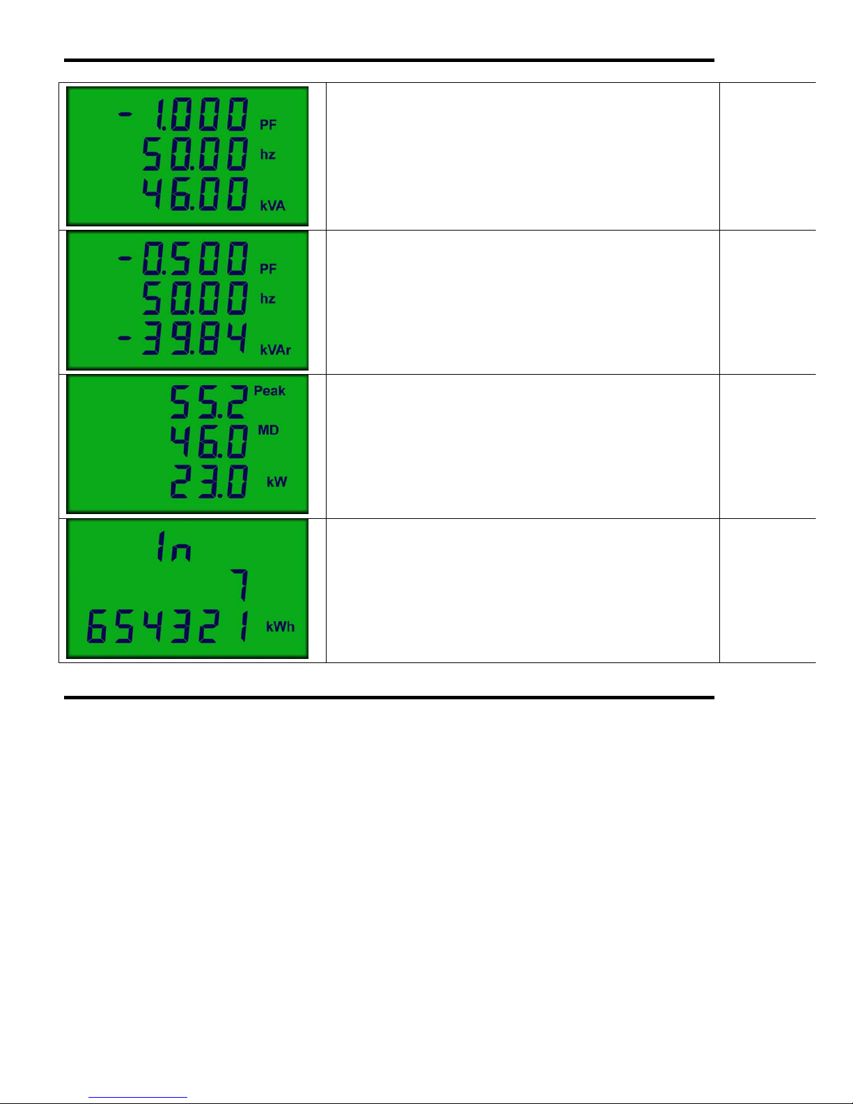
PF, Hz, VA
Power Factor (‘-’ denotes capacitive).
Frequency detected on voltage input signal.
Instantaneous VA calculated as Volts x Amps.
PF, Hz, var
Power Factor (‘-’ denotes capacitive).
Frequency detected on voltage input signal.
Instantaneous var calculated as:
var = √(VA
2
- W2)
(‘-’ denotes Export).
Watts Demand
MD based on rolling average of instantaneous kW :
Peak kW MD (largest since last reset)
Current Period kW MD
Instantaneous kW
Import Wh Register
Instantaneous watts integrated over time is
accumulated in this register while the load is receiving
real power.
The most significant 7th digit is displayed on the
middle line.
Page 11
Meter Operation
Single Phase MultiCube Page 11
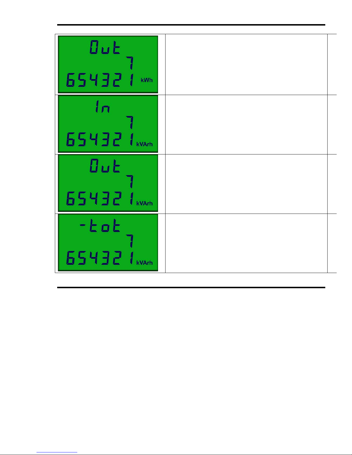
Export Wh Register
Instantaneous watts integrated over time is
accumulated in this register while the load is
generating real power.
The most significant 7th digit is displayed on the
middle line.
Import varh Register
Instantaneous var integrated over time is accumulated
in this register while the load is receiving real power.
The most significant 7th digit is displayed on the
middle line.
Export varh Register
Instantaneous var integrated over time is accumulated
in this register while the load is generating real power.
The most significant 7th digit is displayed on the
middle line.
Total varh Register
The absolute sum of import and export varh registers.
A ‘-‘ sign indicates an instantaneous export condition.
The most significant 7th digit is displayed on the
middle line.
Page 12
Meter Operation
Page 12 Single Phase MultiCube
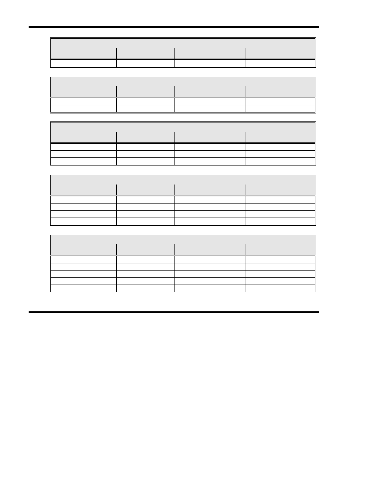
Single Phase MultiCube Type 1 Menus
I V P E
Amps & Peak Amps Volts & Peak Volts PF, Frequency, Watts Import Wh
Single Phase MultiCube Type 2 Menus
I V P E
Amps & Peak Amps Volts & Peak Volts PF, Frequency, Watts Import Wh
PF, Frequency, var
Single Phase MultiCube Type 3 Menus
I V P E
Amps & Peak Amps Volts & Peak Volts PF, Frequency, Watts Import Wh
Amps Demand & Peak PF, Frequency, VA
PF, Frequency, var
Single Phase MultiCube Type 4 Menus
I V P E
Amps & Peak Amps Volts & Peak Volts PF, Frequency, Watts Import Wh
Amps Demand & Peak PF, Frequency, VA Export Wh (No Pulse)
PF, Frequency, var
Watts Demand & Peak
Single Phase MultiCube Type 5 Menus
I V P E
Amps & Peak Amps Volts & Peak Volts PF, Frequency, Watts Import Wh
Amps Demand & Peak PF, Frequency, VA Export Wh
PF, Frequency, var Import varh
Watts Demand & Peak Export varh
Total varh
Page 13
Meter Operation
Single Phase MultiCube Page 13
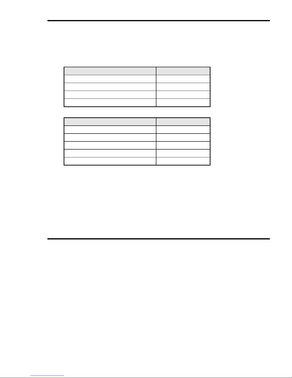
2.4 Display Scaling
The MultiCube scales it’s displays automatically to provide the optimum resolution
dependant on user settings (CT and PT Primary). This provides direct readings with
decimal points and legends automatically selected (e.g. kW or MW etc).
2.4.1 Voltage Scaling (Phase, Peak)
PT Setting Example Display
60V - 80V 20.00 V
81V - 800V 200.0 V
801V – 8,000V 2.000 kV
8,001V – 50,000V 20.00 kV
2.4.2 Current Scaling (Phase, Peak, MD, Pk MD)
CT Setting Example Display
5A - 8A 5.000 A
9A - 80A 50.00 A
81A - 800A 500.0 A
801A – 8,000A 5.000 kA
8,001A – 20,000A 20.00 kA
Page 14
Meter Operation
Page 14 Single Phase MultiCube
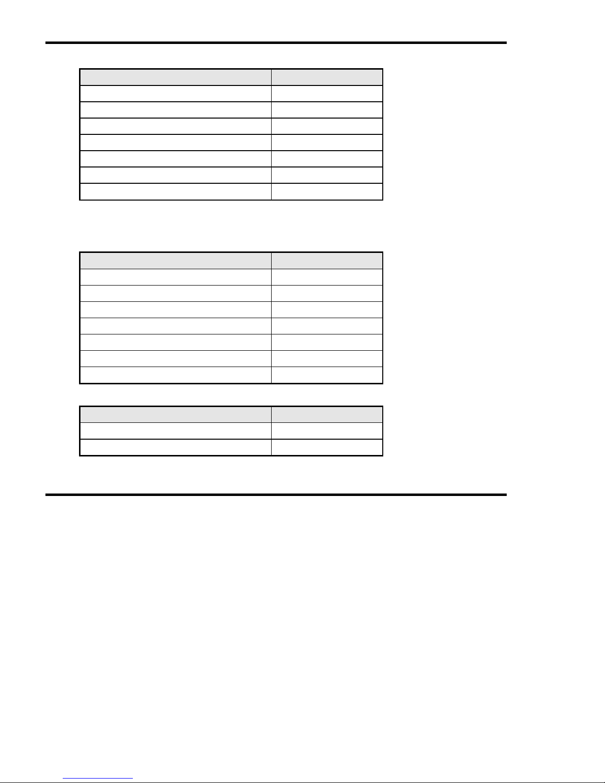
2.4.3 Per Phase & System Power Scaling (W, VA, var)
PT Setting x CT Setting Example Display
300VA – 3,000VA 2000.1 W
3,001VA – 30,000VA 2.000 kW
30,001VA – 300,000VA 20.00 kW
300,001VA – 3,000,000VA 200.0 kW
3,000,001VA – 30,000,000VA 2000 kW
30,000,001VA – 300,000,000VA 20.00 MW
300,000,001VA – 1,000,000,000VA 200.0 MW
Note:
Rolling kW Demand, Peak Demand and kW on the MD page are displayed with 1
less digit of resolution than those above. (e.g. 20.00 kW becomes 20.0 kW)
2.4.4 Energy Registers (Wh, VAh, varh)
PT Setting x CT Setting Example Display
300VA – 3,000VA 9999.999 kWh
3,001VA – 30,000VA 99999.99 kWh
30,001VA – 300,000VA 999999.9 kWh
300,001VA – 3,000,000VA 9999999 kWh
3,000,001VA – 30,000,000VA 99999.99 MWh
30,000,001VA – 300,000,000VA 999999.9 MWh
300,000,001VA – 1,000,000,000VA 9999999 MWh
2.4.5 Miscellaneous (Frequency, PF, THD)
All Settings Example Display
Power Factor 1.000 PF
Frequency 50.00 hz
Page 15

Meter Operation
Single Phase MultiCube Page 15
2.5 Energy Register Reset
All accumulating energy registers may be simultaneously reset to zero using the front
panel keys. Once reset, energy readings are lost forever so great care must be taken
when using this feature. To reset all energy registers
•
Select any energy display page as described above
•
Press
P
and E keys together and Hold for 5 seconds.
2.6 Peak Voltage Reset
The peak voltage reading may be reset to zero using the front panel keys. Once
reset the old value will be immediately replaced by the latest instantaneous reading
and subsequent peaks as they occur. To reset Peak Voltage
•
Select the Voltage display page as described above
•
Press
P
and E keys together and Hold for 5 seconds.
2.7 Peak Current Reset
The peak current reading may be reset to zero using the front panel keys. Once
reset the old value will be immediately replaced by the latest instantaneous reading
and subsequent peaks as they occur. To reset Peak Amps
•
Select the Current display page as described above
•
Press
P
and E keys together and Hold for 5 seconds.
2.8 Peak Demand Reset
Peak rolling demand readings (Amps and kW) may be reset to zero using the front
panel keys. At the end of the next sub period the peak will be set to the latest rolling
average value. To reset the Peak MD
•
Select the Ampere Demand or Watts Demand display page as required
•
Press
P
and E keys together and Hold for 5 seconds.
Page 16
Meter Operation
Page 16 Single Phase MultiCube
2.9 Isolated Pulse Outputs
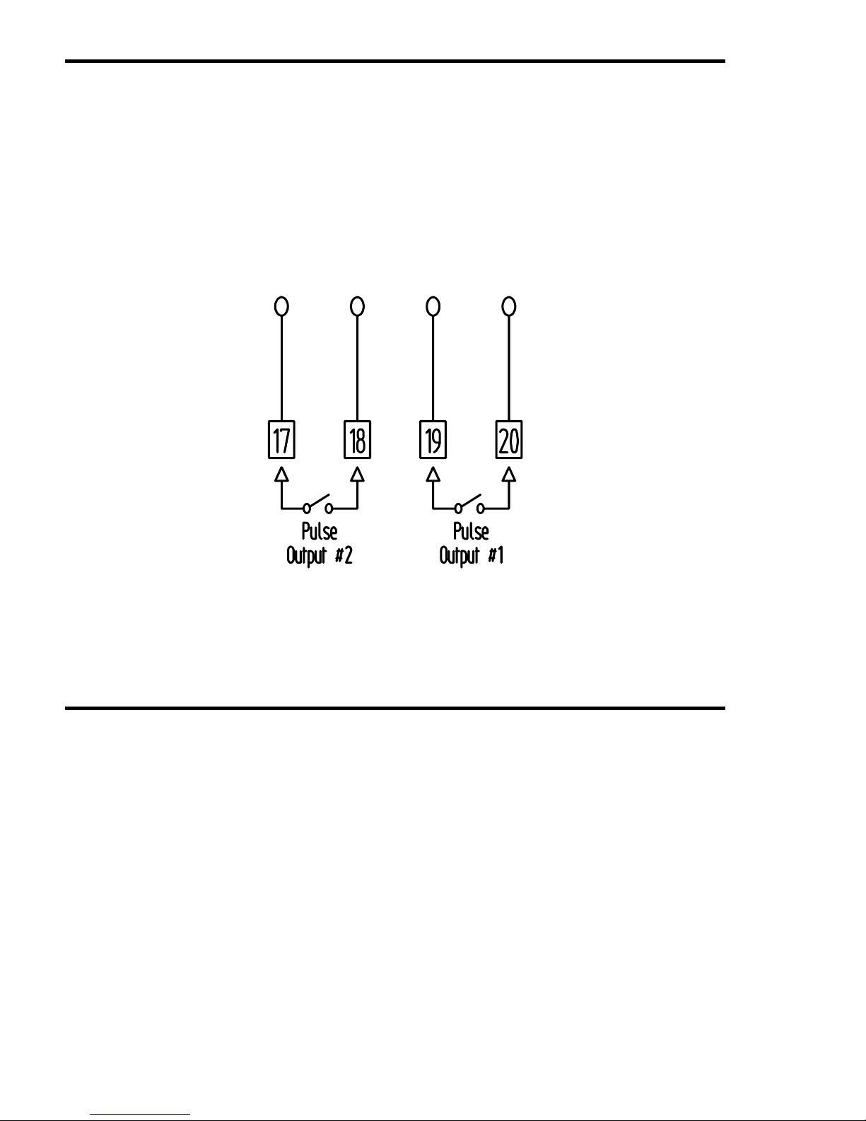
MultiCube meters which display kWh and/or Export kWh incorporate isolated pulse
output(s). These outputs provide a simple interface to external systems such as
building management centres etc.
Each output takes the form of a normally open, volt free contact pair which provides a
low resistance, for 100mS, at the end of a pre-set number of increments of the
associated energy register (‘pulse rate’). The pulse rate of each output may be
programmed by the user to match the requirements of the external system. For
further details on programming the MultiCube refer to Section 4.
Figure 2.1 Pulse Output Connection
Page 17
Installation
Single Phase MultiCube Page 17
3. Installation
3.1 Panel Mounting
Panels should be of thickness 1mm to 4mm with a square cut-out of 92mm (+0.8 -
0.0). A minimum depth of 72mm should be allowed behind the panel for the meter.
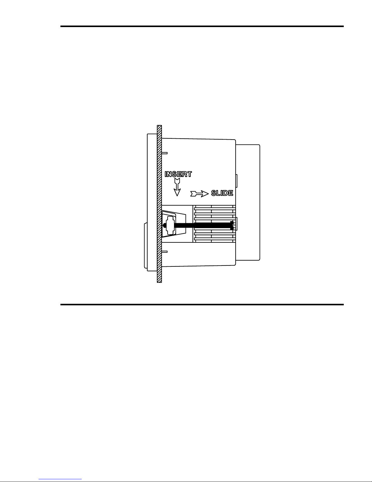
Remove the panel mounting clips and insert the meter into the cut-out from the front
of the panel. Push the meter home. Ensure the screws in each panel mount clip are
fully retracted and insert the clips as shown in the diagram below. Tighten the screws
to secure the meter firmly in the panel.
DO NOT OVERTIGHTEN.
Figure 3-1 Fitting The Meter in a Panel
Page 18

Installation
Page 18 Single Phase MultiCube
3.2 CT Connections
The MultiCube is designed for use with an external current transformer (CT).
Recommended types should conform to Class 1 per IEC 60044-1. The secondary of
the CT should be specified to suit the input rating defined on the meter label. Cables
used for the current circuit should have a maximum conductor size of 4.0mm
2
and
should be kept as short as possible to reduce cable losses loading the CT secondary.
The CT Input to the meter is isolated from all other parts of the circuit.
WARNING :
NEVER leave the secondary of a current transformer open circuit
while a primary current flows. In this condition dangerous voltages
may be produced at the secondary terminals.
3.3 Voltage Connections
Cables used for the voltage measurement circuit should be insulated to a minimum of
600V AC and have a minimum current rating of 250mA. The maximum conductor
size is 4.0mm
2
.
An external protection fuse is recommended for the voltage measurement input. This
should be rated at 160mA maximum, Type F, and should be able to withstand
voltages greater than the maximum input to the meter.
Page 19

Installation
Single Phase MultiCube Page 19
3.4 Auxiliary Mains Supply (L & N)
The MultiCube uses an isolated auxiliary mains supply separate from the voltage
measurement input. This may be connected separately or in parallel with the
measurement inputs provided the ratings detailed on the instrument label are not
exceeded.
Separate connection of the auxiliary mains is required, for example, when :
•
A suitable supply voltage is not available locally.
•
Measurement voltages are expected to vary over a wide range
•
A backup supply is required to maintain meter display
External fusing is required for safe installation. The external fuse should be rated at
250V, 100mA Type T.
WARNING :
CHECK the instrument LABELS for correct input ratings.
Incorrectly rated inputs may permanently damage the device
NOTE: The MultiCube may be supplied with a non-standard auxiliary mains supply
type (eg 72V DC). In this case separate documentation will be available, providing
specific installation/safety information.
Page 20
Installation
Page 20 Single Phase MultiCube
3.5 Connection Schematics
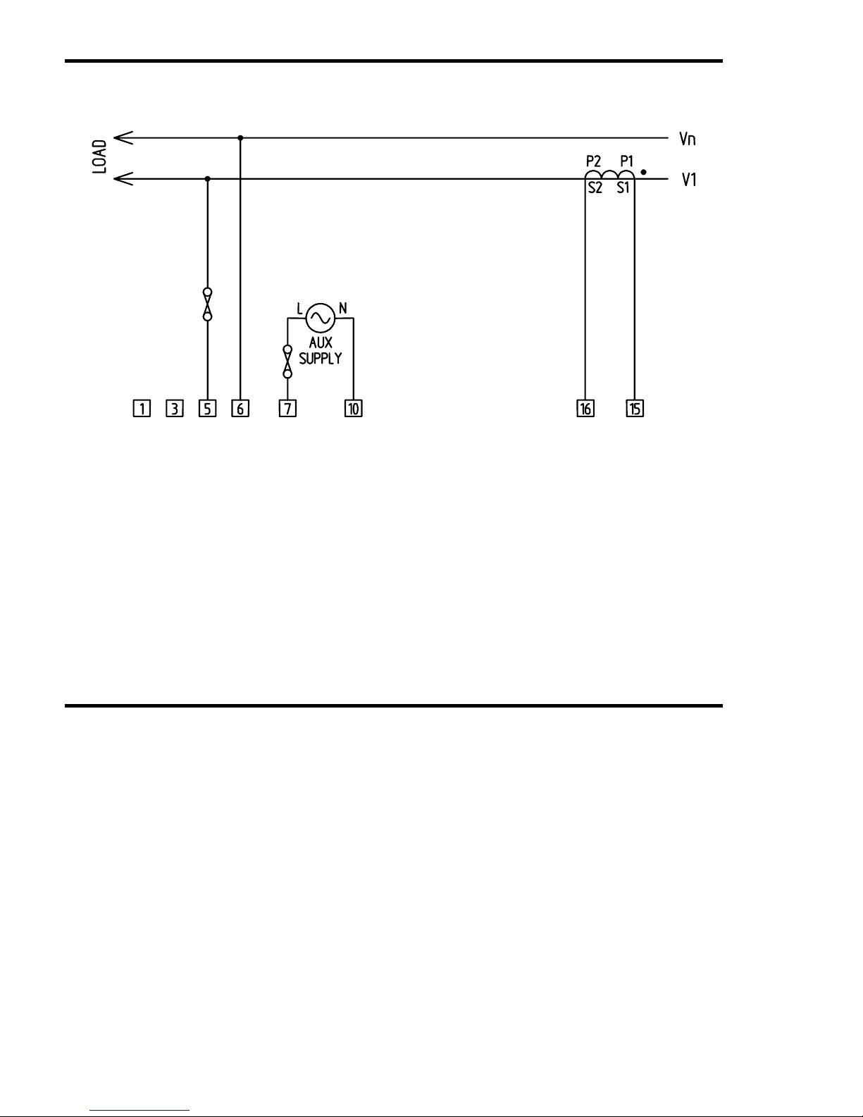
Figure 3-2 Single Phase Connection
Page 21

Programming
Single Phase MultiCube Page 21
4. Programming
4.1 Description
The MultiCube is designed for use in a wide variety of systems. A range of
programmable features allow the unit to be set-up for a specific application.
Programming is available using the front panel keypad and display while the unit is
operational.
4.2 Entering and Exiting Programming Mode
To enter programming, Press I and V together and hold for 5 seconds.
When all user programmable settings are complete, Press
I
and V together and
hold for 5 seconds to return to measurement mode.
Page 22
Programming
Page 22 Single Phase MultiCube
4.3 Setting The CT Primary Current
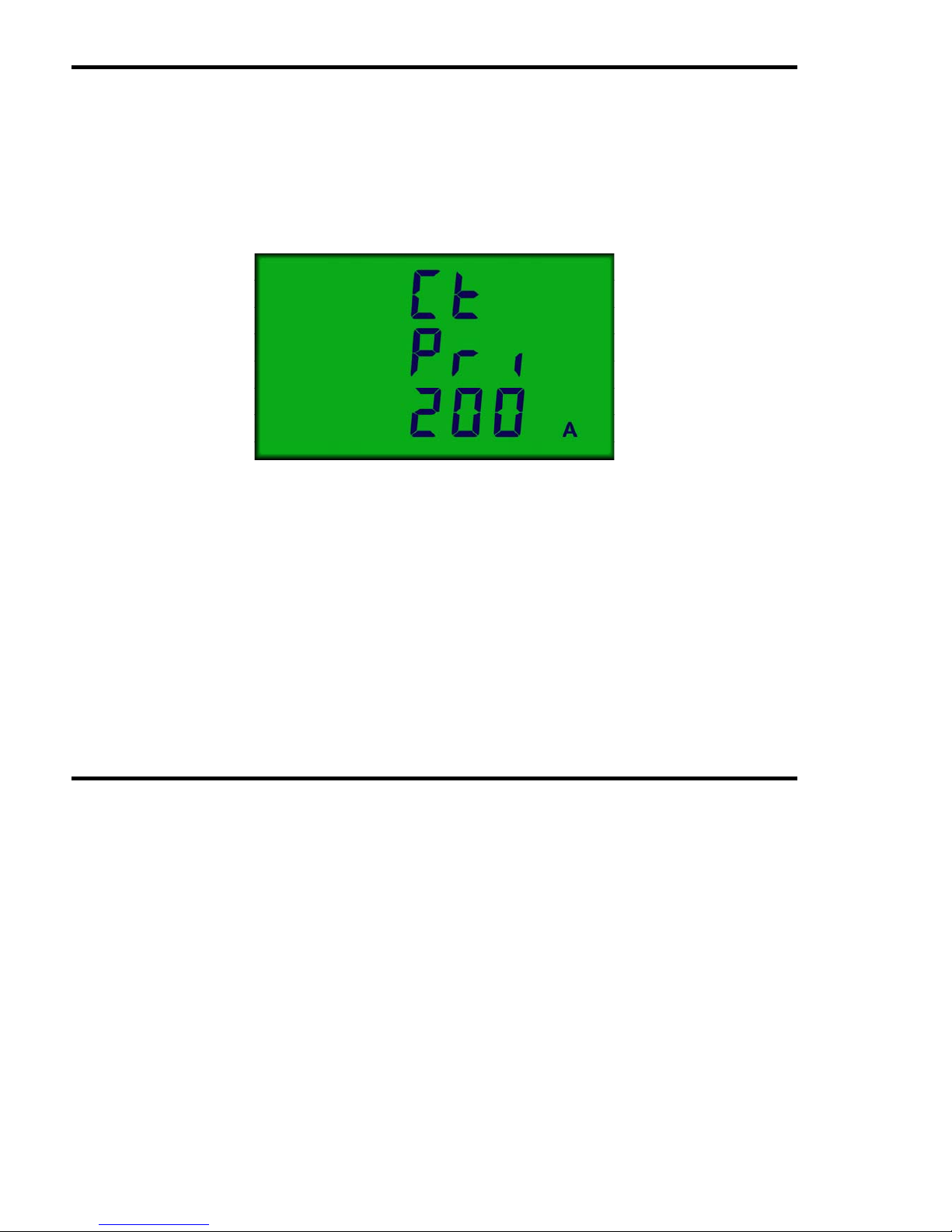
The first item in the programming menu allows the user to set the CT Primary current,
in the range 5A to 20000A, to match the primary of the current transformer connected
to the meter inputs. The secondary of the CT must match the nominal input current
specified on the meter label. Once set, the constant acts as a multiplying factor in the
internal calculation of relevant measurements.
Figure 4-1 Setting The CT Primary Constant
Press
U
to increase the CT Primary Constant in steps of 1 Amp.
Press
V
to decrease the CT Primary Constant in steps of 1 Amp.
Press
↵
and hold for 2 seconds when done.
Page 23
Programming
Single Phase MultiCube Page 23
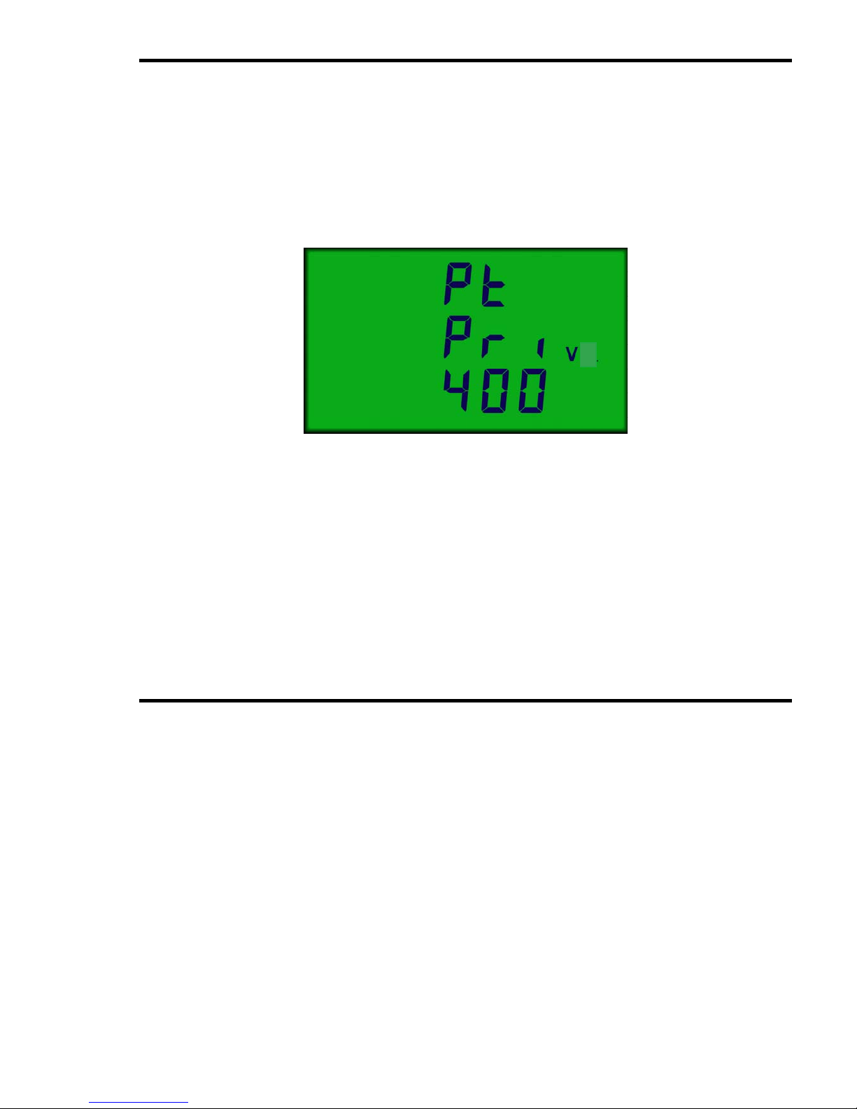
4.4 Setting The PT Primary Voltage
The next item in the programming menu allows the user to set the PT Primary lineline voltage, in the range 60V to 50,000V, to match the primary of the potential
transformers connected to the meter inputs. The secondary of the PTs must match
the nominal line-line input voltage specified on the meter label. If no potential
transformers are fitted the PT setting must match the nominal line-line input voltage
specified on the meter label.
Figure 4-2 Setting The PT Primary Constant
Press
U
to increase the PT Primary Constant in steps of 1 Volt.
Press
V
to decrease the PT Primary Constant in steps of 1 Volt.
Press
↵
and hold for 2 seconds when done.
Page 24
Programming
Page 24 Single Phase MultiCube
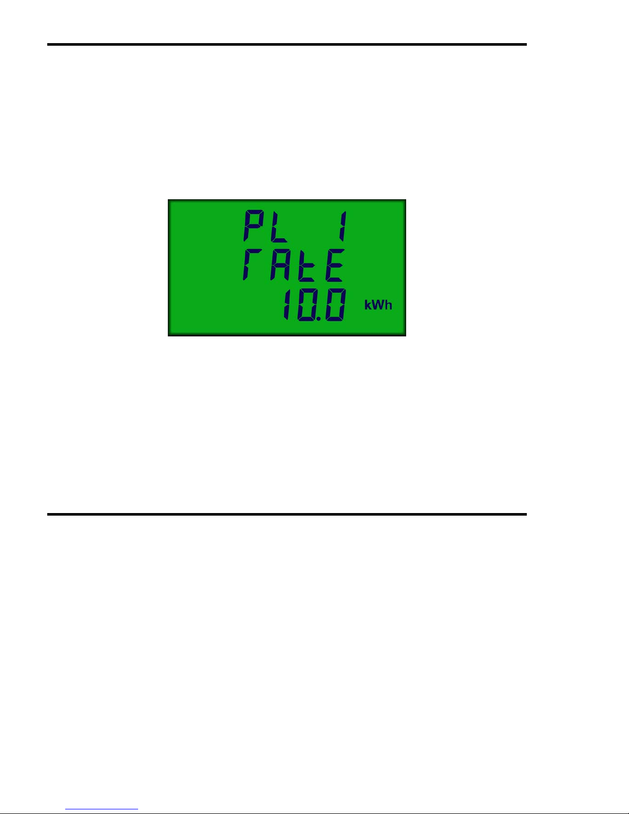
4.5 Setting Pulse Output 1 Rate
Isolated pulse output #1 may be set to provide a single pulse at the end of every 1,
10, or 100 increments of the Wh register irrespective of display scaling and decimal
point. This allows the unit to be configured to suit a wide variety of data logging,
building management type applications.
During programming, the Pulse Output #1 Rate is displayed scaled as the Wh
register for convenience. A display of PL 1 rAtE 10.0 kWh indicates that a single
pulse will occur, at output #1, at the end of each 10 kWh.
Figure 4-3 Setting The Pulse Output #1 Rate
Press
U
to increase the Pulse Output Rate by a factor of 10.
Press
V
to decrease the Pulse Output Rate by a factor of 10.
Press
↵
and hold for 2 seconds when done.
Page 25
Programming
Single Phase MultiCube Page 25
4.6 Setting Pulse Output 2 Rate
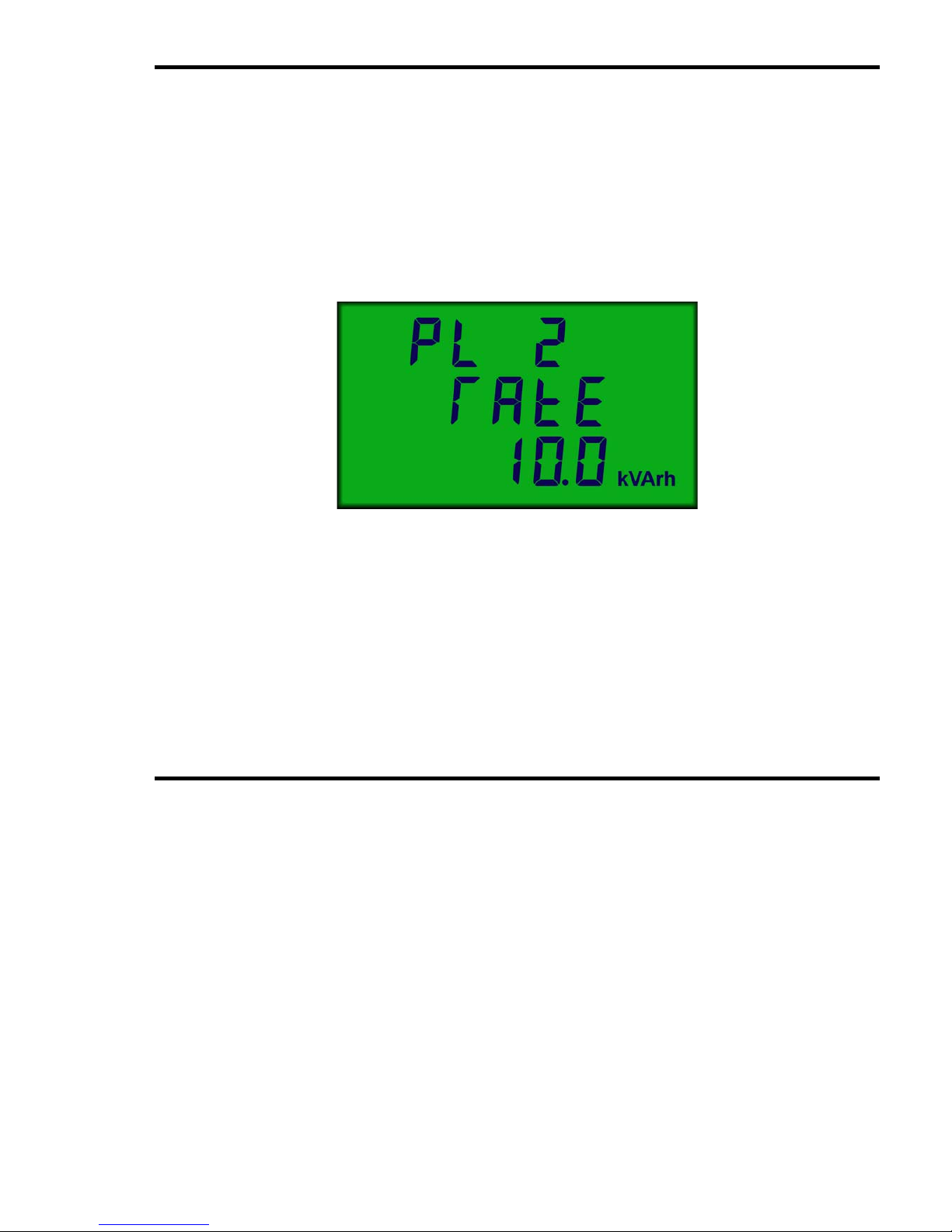
Isolated pulse output #2 may be set to provide a single pulse at the end of every 1,
10, or 100 increments of the Total varh register irrespective of display scaling and
decimal point. This allows the unit to be configured to suit a wide variety of data
logging, building management type applications.
During programming, the Pulse Output #2 Rate is displayed scaled as the total varh
register for convenience. A display of PL 2 rAtE 10.0 kVArh indicates that a
single pulse will occur, at output #2, at the end of each 10 kvarh.
Figure 4-4 Setting The Pulse Output #2 Rate
Press
U
to increase the Pulse Output Rate by a factor of 10.
Press
V
to decrease the Pulse Output Rate by a factor of 10.
Press
↵
and hold for 2 seconds when done.
Page 26
Programming
Page 26 Single Phase MultiCube
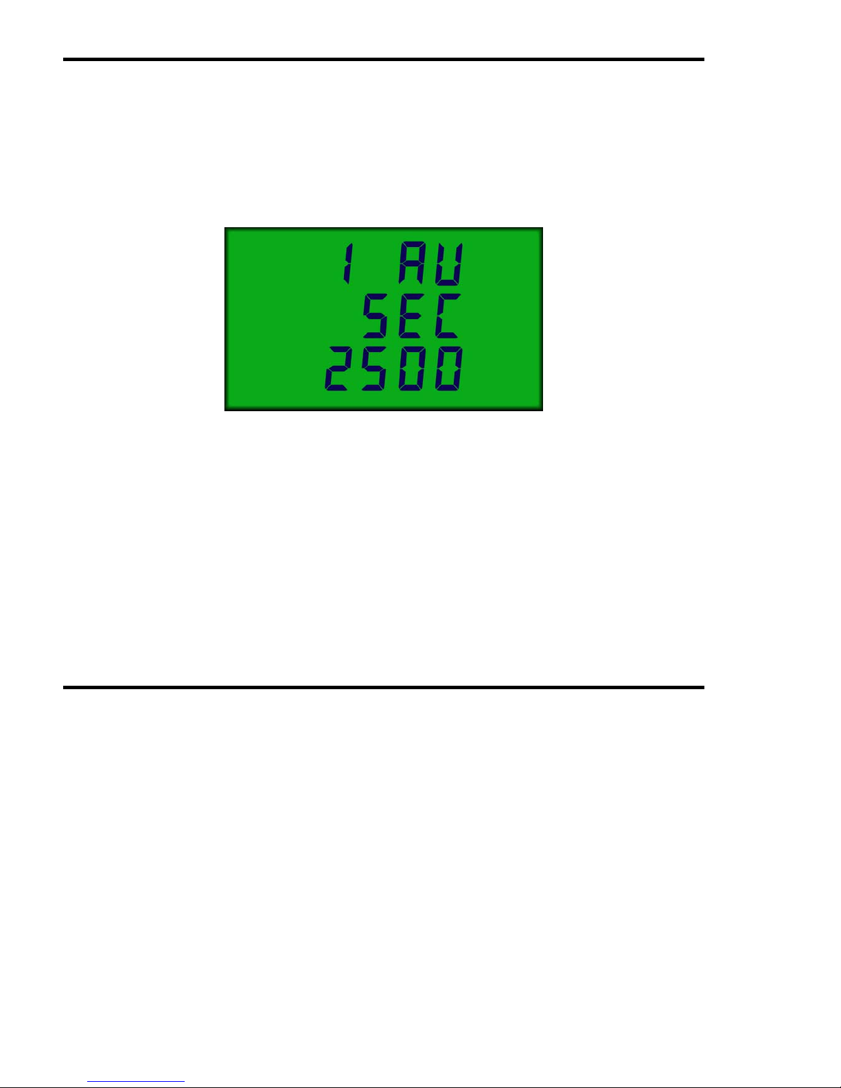
4.7 Setting The Ampere Demand Period
The averaging period used in calculation of Ampere Rolling Demand (ref.
Section 2.1.1) may be set in the range 10-2500 seconds (steps of 10s). This period
may be selected to set a convenient filter for short term fluctuations in input power, as
required.
During programming, the Average Period is displayed in seconds.
Figure 4-5 Setting Ampere Demand Period
Press
U
to increase the Averaging Period by 10 seconds.
Press
V
to decrease the Averaging Period by 10 seconds.
Press
↵
and hold for 2 seconds when done.
Page 27
Programming
Single Phase MultiCube Page 27
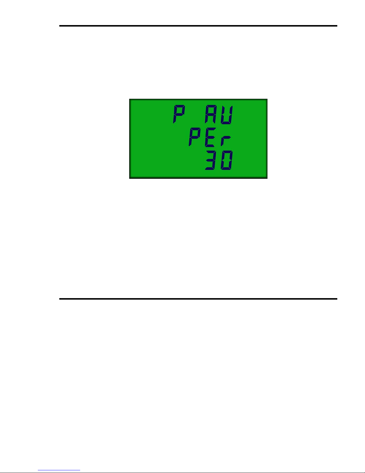
4.8 Setting The kW Rolling Average Period
The averaging period used in calculation of Watts Rolling Demands (ref.
Section 2.1.1) may be set in the range 1-60 minutes. This period may be selected to
match specific standards, or to set a convenient filter for short term fluctuations in
input power, as required.
During programming, the Average Period is displayed in minutes.
Figure 4-6 Setting Watts Rolling Demand Period
Press
U
to increase the Averaging Period by 1 minute.
Press
V
to decrease the Averaging Period by 1 minute.
Press
↵
and hold for 2 seconds when done.
Page 28
Specification
Page 28 Single Phase MultiCube
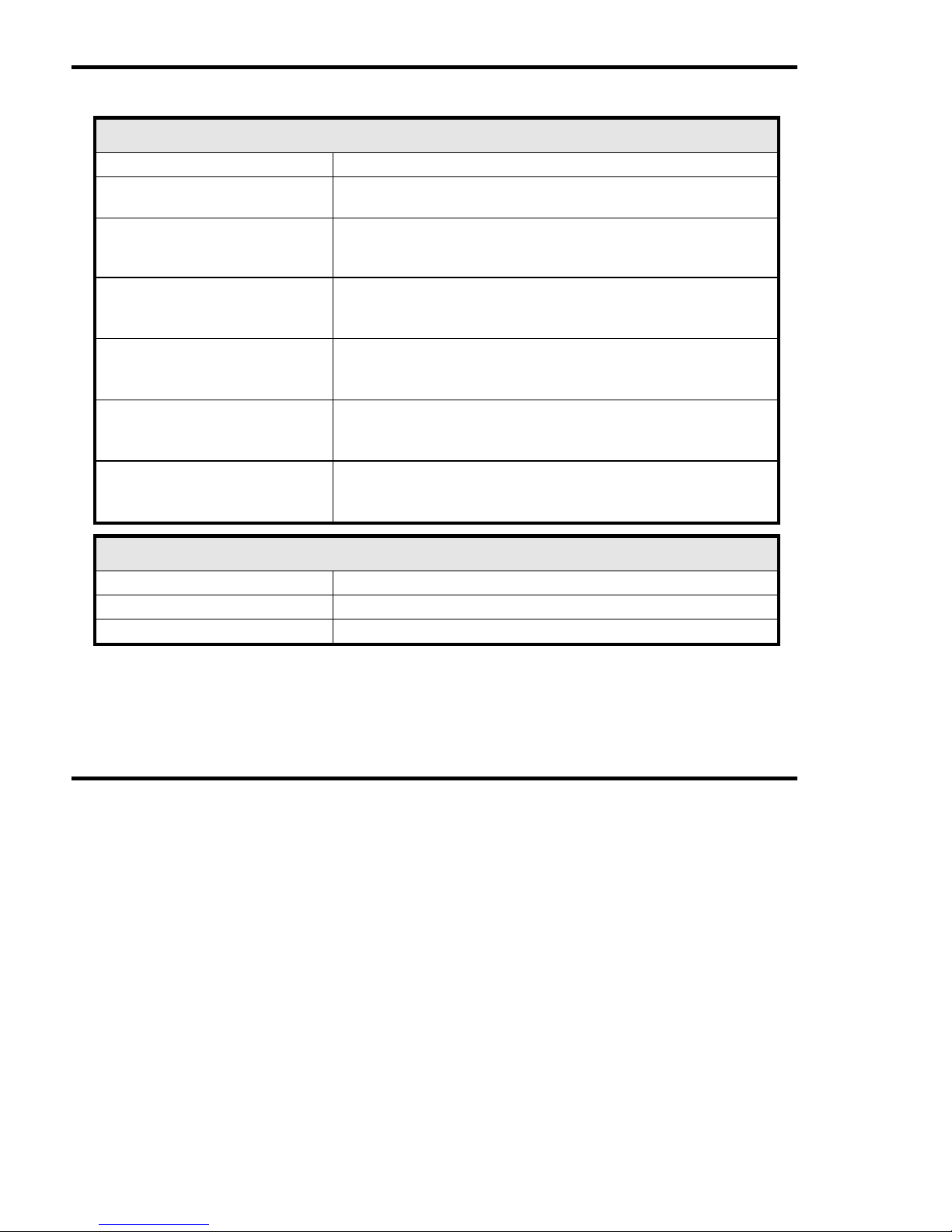
5. Specification
Inputs
System
1-Phase 2 Wire Balanced/Unbalanced Loads
Voltage
Vb. 230 Volt. 1-Phase 2 Wire
Vb. 120 Volt optional
Current
Ib 5 Amp from external current transformer (CT)
Ib 1 Amp optional
Fully Isolated (2.5kV / 1 minute)
Measurement Range
Voltage
Current
20% to 120%
0.5% to 120%
Frequency Range
Fundamental
Harmonics
45 to 65Hz
Up to 20th harmonic
Input Loading
Voltage
Current
Less than 0.1 VA
Less than 0.1 VA
Overloads
Voltage
Current
x2 for 2 seconds maximum
x40 for 0.5 seconds maximum
Auxiliary Supply
Standard
230 Volt 50/60Hz ±15%
Options
110 Volt 50/60Hz ±15%. (Others to order)
Load
5 VA Maximum
Page 29
Specification
Single Phase MultiCube Page 29
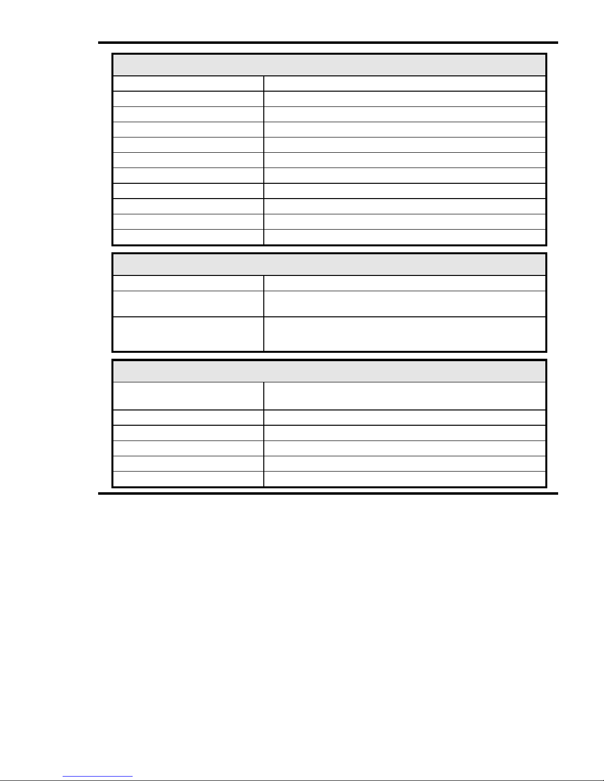
Accuracy
Current
0.2% Ib (1.0% Rdg. 0.05 Ib ≤ Iph ≤ 1.2 Ib) ±1 digit.
Voltage
0.2% Vb (1.0% Rdg. 0.2 Vb ≤ V
ph
≤
1.2 Vb) ±1 digit.
Watts
0.4% FS (1.0% Rdg. 0.05FS ≤ P ≤ 1.2FS) ±1 digit.
VA
0.6% FS (1.5% Rdg. 0.05FS ≤ Q ≤ 1.2FS) ±1 digit.
var
0.8% FS (2.0% Rdg. 0.05FS ≤ S ≤ 1.2FS) ±1 digit.
PF
± 0.2 Degrees
Frequency
±0.05Hz. 45Hz ≤ F ≤ 65Hz
Wh Register
Class 1.0 EN 61036
VAh Register
Class 2.0
varh Registers
Class 2.0 IEC 1268
Timebase
Better than 100ppm
Display
Display Type
Custom, supertwist, LCD with LED backlight
Data Retention
10 years minimum
Stores energy registers, user settings, and peaks
Display Format
Display Update
3 Lines 12mm digits + 3.8mm custom legends
1 second
Digital (Pulse) Outputs
Function
1 pulse / energy unit
(Output #1=N Import Wh, Output #2=N Export Wh)
Scaling
Settable 1,10 or 100 counts of associated register
Pulse Period
100ms. (2ms Rise, 2ms Fall)
Type
N/O Volt free contact. Optically isolated BiFET
Contacts
100mA AC/DC max, 100V AC/DC max
Isolation
2.5kV (50V #1 to #2)
Page 30
Specification
Page 30 Single Phase MultiCube
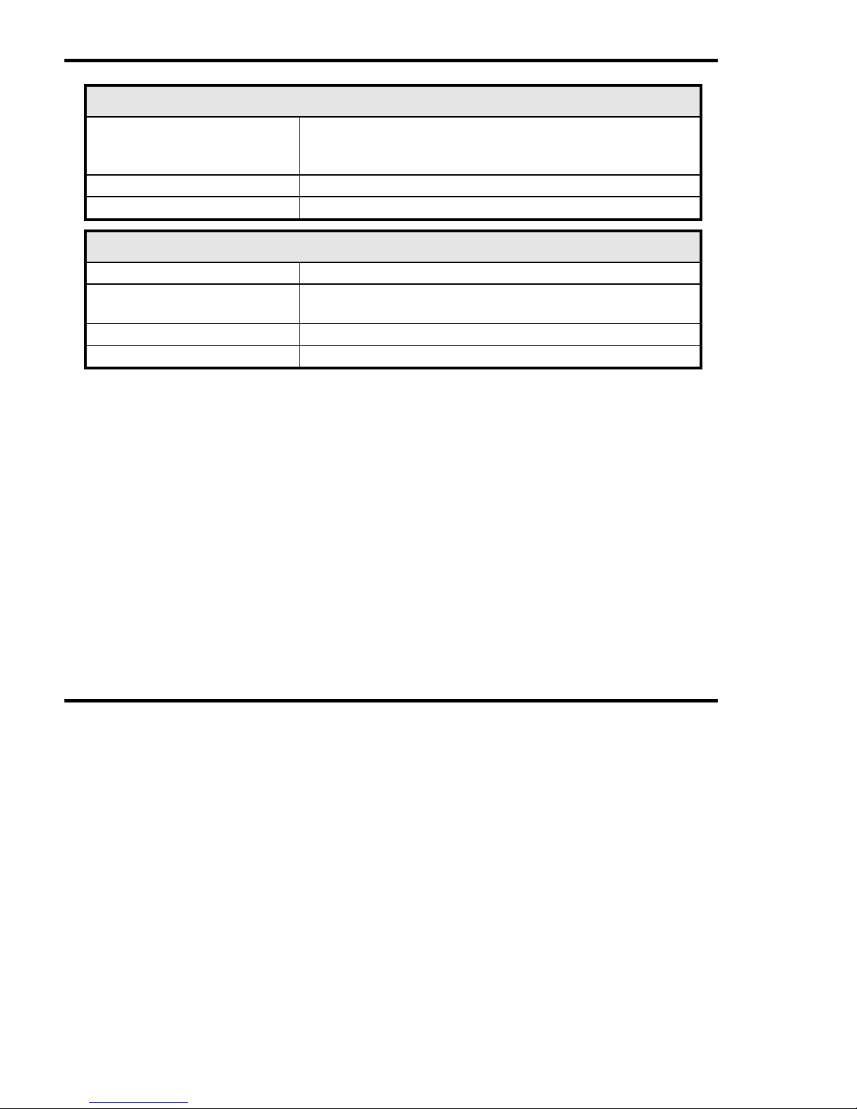
General
Temperature
Operating
Storage
-10 deg C to +65 deg C
-25 deg C to +70 deg C
Environment
IP54
Humidity
<75% non-condensing
Mechanical
Enclosure
DIN 96mm x 96mm Mablex ULV94-V-O
Dimensions
96mm x 96mm x 80mm (72mm behind panel)
130mm behind panel with options unit fitted
Weight
Approx. 400g
Terminals
Rising Cage. 4.0mm2 cable max
Page 31

Page 32

Northern Design (Electronics) Ltd,
228 Bolton Road, Bradford,
West Yorkshire, BD3 0QW, England.
Telephone: +44 (0) 1274 729533
Fax: +44 (0) 1274 721074
Email: [email protected]
Copyright Northern Design 2004
 Loading...