

nct 101T, 104T, 115T User Manual

®
NCT
101T, 104T, 115T
Controls for Lathes
Operator`s Manual
Valid from software version x.066

Produced and developed by NCT Automation kft.
H1148 Budapest Fogarasi út 7
F Phone: (+36 1) 467 63 00
F Fax:(+36 1) 467 63 09
E-mail: nct@nct.hu
Home Page: www.nct.hu

Contents
Introduction. .............................................................. 7
1 Operator’s Panel.......................................................... 8
1.1 The NC Control Panel: Display Unit and Data Input Keyboard.. . . . . . . . . . . . . . . . . . 8
1.1.1 Data Input Keyboard................................................ 11
1.1.2 Information Displayed in General Displaying Area and the Status Bar. . . . . . . . . 13
1.1.3 Indication of Ready Status of Control.. . . . . . . . . . . . . . . . . . . . . . . . . . . . . . . . . . 15
1.2 Machine Control Board. ................................................ 15
2 General Operating Knowledge.............................................. 19
2.1 Screen Menu..........................................................19
2.2 Action Menu.......................................................... 22
2.3 Data Input............................................................ 22
3 General Displaying Areas and Actions Executed on Them....................... 24
3.1 Turn-on Process of the Control. .......................................... 25
3.1.1 First Phase of the Turn-on Process and its Error Messages. . . . . . . . . . . . . . . . . . 25
3.1.2 Second Phase of the Turn-on Process and its Error Messages. . . . . . . . . . . . . . . . 25
3.2 POSITION Screens. ................................................... 27
3.3 CHECK Screens....................................................... 29
3.3.1 PROGRAM TEXT Screen, Listing of Running Program.. . . . . . . . . . . . . . . . . . . 29
3.3.2 FUNCTION Screen, Subprogram and Macro Levels. . . . . . . . . . . . . . . . . . . . . . . 29
3.3.3 LAST and ACTIVE screens. G Codes and Compensations.. . . . . . . . . . . . . . . . . 30
3.3.4 OPERATOR’S PANEL Screen. ......................................31
3.3.5 MESSAGES Screen................................................ 32
3.4 PROGRAM Screens.................................................... 33
3.4.1 DIRECTORY Screen. ..............................................33
3.4.2 VIEW Screen. .................................................... 35
3.4.3 EDIT Screen...................................................... 36
3.4.4 BLOCK INPUT. .................................................. 36
3.5 OFFSETS Screens..................................................... 38
3.5.1 WORK OFFSETS Screen............................................ 38
3.5.2 TOOL OFFSETS Screen. ........................................... 39
3.5.3 WORK OFFSET MEASURE Screen................................... 42
3.5.4 TOOL LENGTH OFFSET MEASURE Screen. . . . . . . . . . . . . . . . . . . . . . . . . . . 43
3.5.5 RELATIVE POSITION OFFSETS Screen.. . . . . . . . . . . . . . . . . . . . . . . . . . . . . . 44
3.6 GRAPHIC POSITION Screens........................................... 45
3.6.1 GRAPHIC PARAMETERS Screen.................................... 45
3.6.2 DRAW Screen. ................................................... 47
3.7 SETTING Screens..................................................... 49
3.7.1 Screen of LOCAL MACRO VARIABLES. . . . . . . . . . . . . . . . . . . . . . . . . . . . . . 49
3.7.2 Screen of COMMON MACRO VARIABLES #100–#199. . . . . . . . . . . . . . . . . . 50
3.7.3 Screen of COMMON MACRO VARIABLES #500–#599. . . . . . . . . . . . . . . . . . 51
3.7.4 TIMER AND COUNTER Screen...................................... 52
3.7.5 TOOL POT TABLE Screen.......................................... 53
3.7.6 PLC TABLE Screen................................................ 55
3.7.7 USER’S PARAMETERS Screen (User’s Params).. . . . . . . . . . . . . . . . . . . . . . . . 56

3.7.8 SECURITY PANEL Screen.......................................... 56
4 Editing Part Programs.................................................... 59
4.1 Structure of Part Program. .............................................. 59
4.2 Division of EDIT Screen during Editing. . . . . . . . . . . . . . . . . . . . . . . . . . . . . . . . . . . . 60
4.3 Basic Editing Functions: Typing, Cursor Moving, Delete, Insert, Select. . . . . . . . . . . 61
4.4 Saving the Edited Program .............................................. 65
4.5 Editor Action Menu.................................................... 65
4.6 File Actions: Save, Save as.............................................. 65
4.7 Edit Actions: Undo, Cut, Copy, Paste, Find and Replace. . . . . . . . . . . . . . . . . . . . . . . 66
4.8 Insert Actions......................................................... 67
4.9 Actions of Window ................................................... 68
4.10 Help............................................................... 68
5 Switching Over Operation Modes........................................... 69
6 Manual Operation Modes. ................................................ 70
6.1 Manual Reference Point Return Mode. .................................... 70
6.2 Jog Mode............................................................ 72
6.3 Incremental Jog Mode.................................................. 74
6.4 Manual Handle Mode. ................................................. 76
7 Actions Executed in Manual Operation Modes................................ 78
7.1 Single Block Operation................................................. 78
7.2 Work Zero Point Offset and Tool Length Offset Measurement. . . . . . . . . . . . . . . . . . 78
7.2.1 Work Zero Point Offset Measurement. . . . . . . . . . . . . . . . . . . . . . . . . . . . . . . . . . 79
7.2.2 Tool Length Offset Measurement inside the Machine. . . . . . . . . . . . . . . . . . . . . . 82
7.2.3 Automatic Tool Length Offset Measurement.. . . . . . . . . . . . . . . . . . . . . . . . . . . . 84
7.2.4 Calibrating Tool Offset Sensor........................................ 85
8 Modes of Automatic Operation............................................. 88
8.1 Automatic Mode. ..................................................... 88
8.1.1 Program Execution in DNC.......................................... 88
8.2 Edit Mode. .......................................................... 90
8.3 Manual Data Input Mode................................................ 91
9 Override Switches........................................................ 93
9.1 Feedrate Override Switch. .............................................. 93
9.2 Rapid Traverse Override Switch.......................................... 94
9.3 Spindle Speed Override Switch........................................... 94
10 Program Execution Start and Stop......................................... 96
10.1 Starting Program Execution............................................. 96
10.2 Feed Stop........................................................... 96
10.3 RESET............................................................. 96
10.4 Programmed Stop: M00................................................ 97
10.5 Conditional Stop: M01. ............................................... 97
10.6 End of Program: M02, M30............................................. 98
11 Intervention in the Course of Program Execution............................. 99
11.1 Conditional Block Skip................................................ 99

11.2 Increasing Feedrate by Means of Rapid Traverse Jog Button. . . . . . . . . . . . . . . . . . . 99
11.3 Changing the Value of Feedrate (F) and Spindle Speed (S). . . . . . . . . . . . . . . . . . . 100
11.4 Stopping Thread Cutting Cycle with STOP Button.. . . . . . . . . . . . . . . . . . . . . . . . . 101
11.5 Intervention by Means of Manual Handle in Automatic Operation.. . . . . . . . . . . . . 101
11.6 Manual Handle Feed. Moving Backwards on Path Programmed.. . . . . . . . . . . . . . . 102
12 Debugging the Part Program............................................. 104
12.1 Single Block Execution............................................... 104
12.2 Dry Run (All Feedrates at High Speed). . . . . . . . . . . . . . . . . . . . . . . . . . . . . . . . . . . 104
12.3 Machine Lock Function............................................... 105
12.4 Other Locking Possibilities. ........................................... 105
12.5 Test Run........................................................... 106
13 Interruption and Restart of Automatic Operation............................ 107
13.1 Interruption of Automatic Operation..................................... 107
13.2 Restart of the Automatic Operation. Modal Information.. . . . . . . . . . . . . . . . . . . . . 107
13.3 Unconditional Restart of Automatic Operation. . . . . . . . . . . . . . . . . . . . . . . . . . . . . 109
13.4 Automatic Operation Restart with BLOCK RESTART Condition. . . . . . . . . . . . . . 114
13.4.1 Return to the Block Start Position by Means of Manual Operation. . . . . . . . . . 114
13.4.2 Return to Block Start Position in Automatic Mode .. . . . . . . . . . . . . . . . . . . . . 114
13.4.3 Cases of Return by Means of BLOCK RESTART Condition. . . . . . . . . . . . . . 115
13.5 Automatic Mode Restart with BLOCK RETURN Condition. . . . . . . . . . . . . . . . . . 118
13.5.1 Return to the Interruption Point by Means of Manual Operation. . . . . . . . . . . . 118
13.5.2 Return to the Interruption Point in Automatic Operation. . . . . . . . . . . . . . . . . . 118
13.5.3 Cases of Return by Means of Condition BLOCK RETURN. . . . . . . . . . . . . . . 119
13.6 Automatic Operation Start after Block Search.. . . . . . . . . . . . . . . . . . . . . . . . . . . . . 122
13.6.1 Pointing at the Desired Block. Entering the Repetition Count.. . . . . . . . . . . . . 122
13.6.2 Command SEARCH.............................................. 123
13.6.3 Command GOTO................................................ 125
13.6.4 Search for INTERRUPTED Block after Mains Voltage Drop-out.. . . . . . . . . . 126
14 Listing of Messages and their Codes....................................... 127
14.1 Local Message...................................................... 127
14.2 Global Messages. ................................................... 127
14.3 Listing of Global Messages............................................ 129
Notes.................................................................... 148
Alphabetical index........................................................ 149
February 5, 2010

© Copyright NCT February 5, 2010
The Publisher reserves all rights for the
contents of this Manual. No reprinting, even
in extracts, is permissible unless our written
consent is obtained. The text of this Manual
has been compiled and checked with utmost
care, yet we assume no liability for possible
errors or spurious data and for consequential losses or damages.

Introduction
Introduction
Dear User,
Thank you for having opted for one of our control systems. It is hoped sincerely that you will be
always satisfied in your work with its facilities.
It should be remembered that the skill of operating the machine can only be learnt in the
possession of the part programming fundamentals. Similarly, no programming is feasible unless
the skills of machine operation are acquired.
THE MACHINE CANNOT BE MANIPULATED OR OPERATED IN SAFETY UNLESS
YOU CAN INTERPRET THE PART PROGRAM AND CHECK IT FOR CORRECT-
NESS!
THE OPERATOR OF THE MACHINE MUST ALWAYS FORESEE ALL CONSE-
QUENCES OF HIS/HER INTERVENTIONS!
Conditions of Operation and Storage
The control system may be operated at an ambient temperature between +10EC és +40EC.
In case the environment temperature increases above +40EC, the control must be turned
off.
The temperature range for storage is –10EC – +60EC.
In the electric cabinet a slight over-pressure must be secured by means of a fan with filter,
mounted on the cabinet. Cleaning, and if needed, replacement of the ventilator filter is a
basic condition for the failure-free operation of the control system.
7
1 Operator’s Panel
1 Operator’s Panel
1.1 The NC Control Panel: Display Unit and Data Input Keyboard
The NC control panel employs the display unit (monitor), the softkeys beneath, and the
data input keyboard.
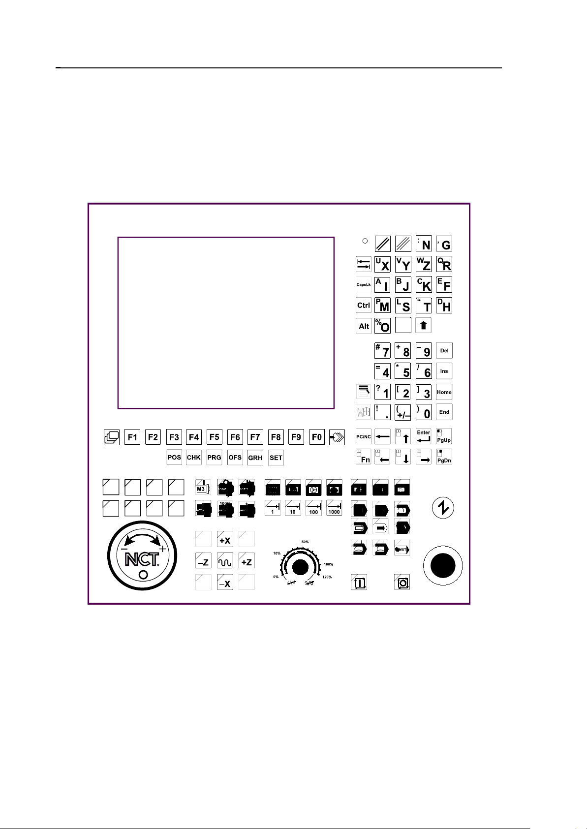
Operator’s panel of NCT101 with 10" color monitor and with machine control
board
8
1 Operator’s Panel
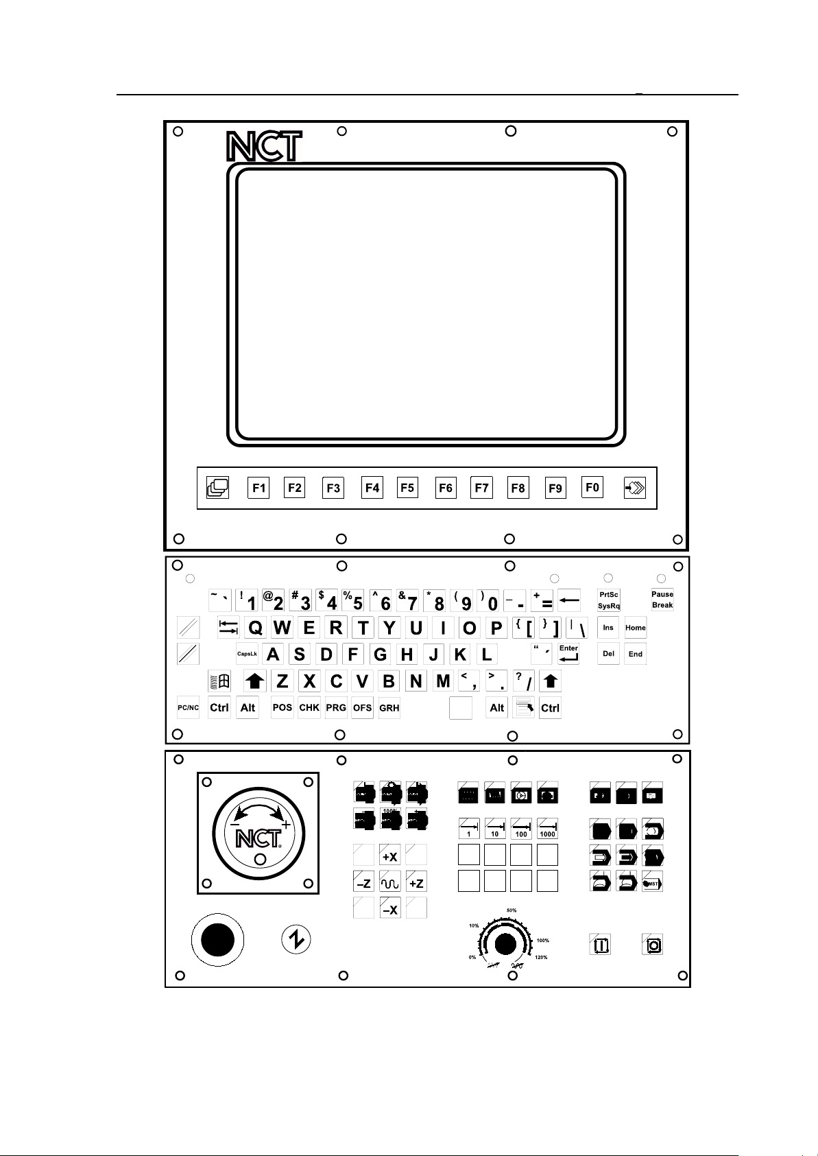
Operator’s panel of NCT104 with 15" color monitor and with optional Machine
control board
9
1 Operator’s Panel
10
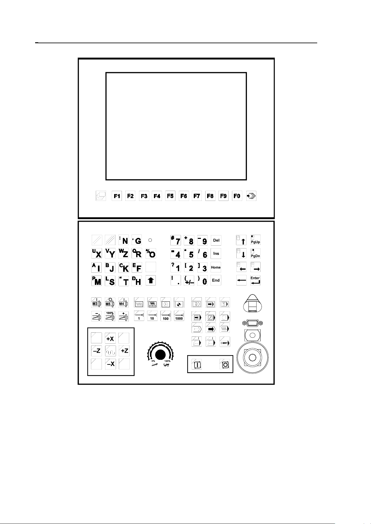
NCT115 operator’s panel with 10" colour monitor and keyboard
1 Operator’s Panel
1.1.1 Data Input Keyboard
The softkeys are directly beneath the screen, integrated with it. The number of softkeys
depends on the screen size, e.g. in case of a screen size of 15" there are 10 softkeys. In both
cases the meaning of these softkeys can be read in the menu bars found in the bottom line of
screen, therefore their meanings may alter. However it is likely, that in some right-side menu
bar there are no captions. This can only mean, that in that situation the softkeys have no
function at all.
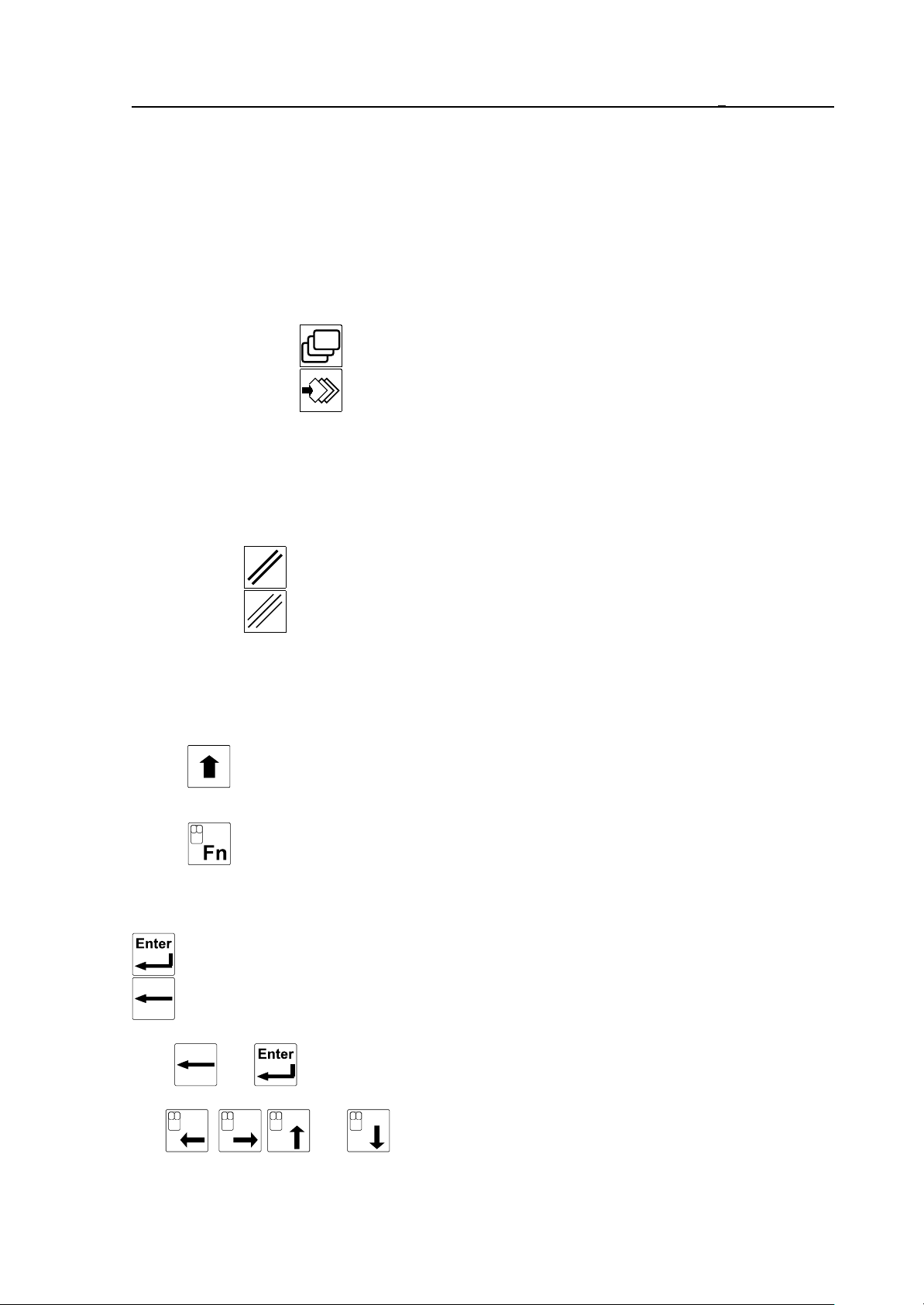
To the left of the first softkey is the
screen menu key , while to the right of the last softkey is the
action menu key . The meaning of these keys is permanent and serve for changing
the meaning of softkeys.
The data- input keyboard may be found beneath or to the right of the monitor. The LED “NC
ready” is placed on the data- input keyboard.
The main key groups found on data input keyboard are as follows::
Delete keys:
RESET for deleting global and
CANCEL for deleting local messages.
Alphabetical keys:
On the panel the letters of English alphabets, the space key without a caption.
Switch keys:
Shift If the shift key is kept pressed down and another key is pushed, lower case
letters or the symbol in the top left corner of the key can be entered.
Fn (NCT101, NCT104). If the Fn key is kept pressed down and another key is
pushed, the symbol in the top right corner of the key can be entered..
Scroll and edit keys:
: New line (s): (Enter)
: Backward movement and delete: (Backspace)
Keys and move the cursor along the characters within a word in course of table
numeric input.
The , , and keys move the cursor the respective direction.
11
1 Operator’s Panel
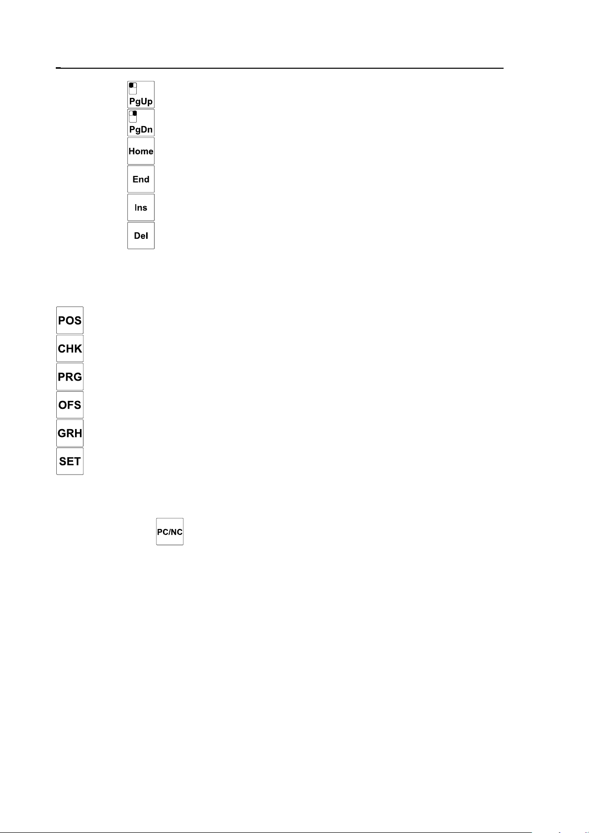
Keys PgUp a nd
PgDn move one page within the text.
Key Home makes the cursor jump to the beginning of line, while
End makes it jump to the end of line..
Key INS switches between insert and overwrite mode, while
DEL deletes one character.
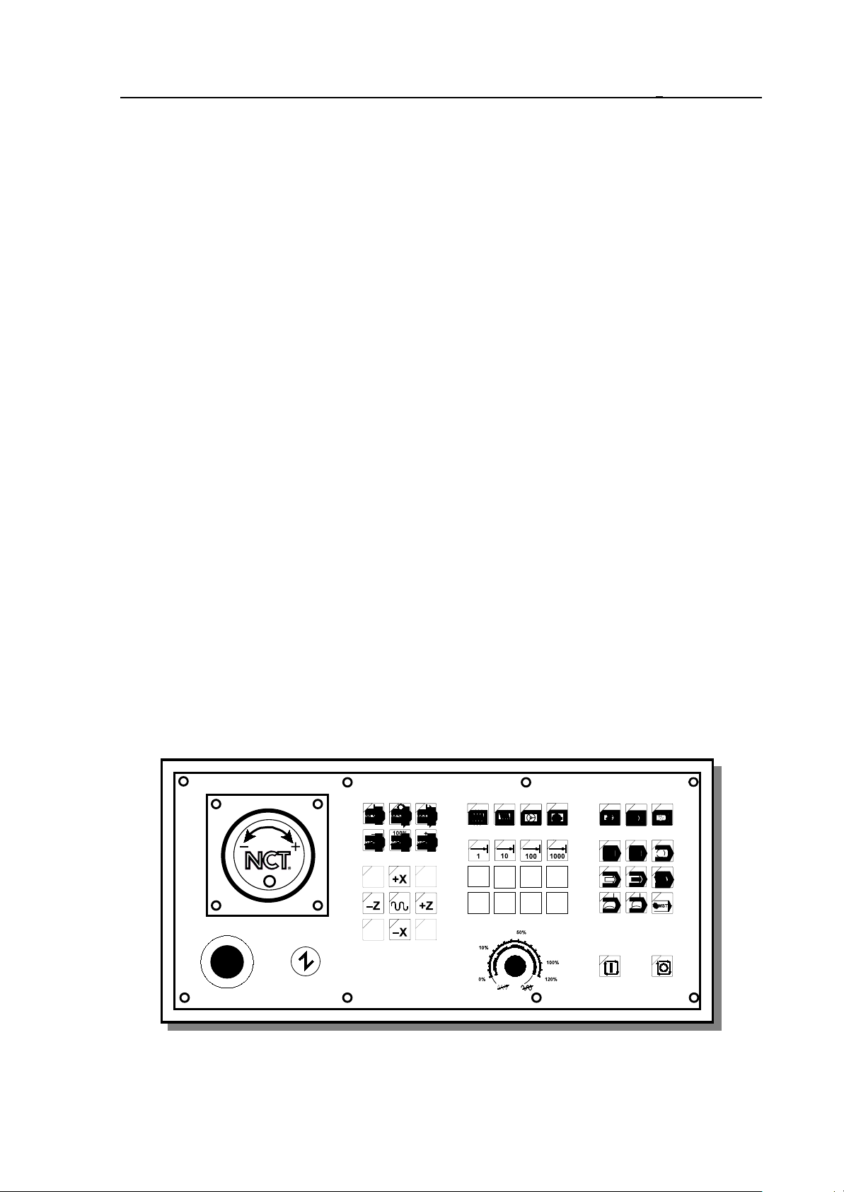
Menu selection keys (NCT101, NCT104):
Other than the use of page and softkeys, screen menu groups can be directly reached with the
help of the following page keys:
paging to Position screen menu,
paging to Check screen menu,
paging to Program screen menu,
paging to Offsets screen menu,
paging to Graphic Position screen menu,
paging to Settings screen menu.
Switch key PC/NC (NCT101, NCT104)
Optionally a PC (Personal Computer) can be added to the control. .
With the help of key the data input keyboard and screen can be switched to the added
PC. In this case the picture of the PC appears on the screen, and the pushbuttons of the data
input keyboard command the PC. The PC and programs developed by NCT that run on PC do
not concern this manual. By the repeated push of the same button the keyboard and the screen
can be switched back to NC. Note, that the mouse symbol found on keys Fn, PgUp, PgDn and
cursor movement buttons indicates functions used on the PC, therefore its description does
not concern this manual.
After turn-on, the screen and keyboard are always under the command of NC.
The above listed units (monitor and keyboard) constitute the permanent part of NC and are
transported together with the control in any case of configuration.
The NC keyboard is fitted with repeater-type keys. This means
) that a depressed key produces an immediate effect,
) that a held-down key produces an effect again after a programmed delay (Typematic
Delay),
12

1 Operator’s Panel
) that, with the key held down permanently, the appropriate code will be entered into the
CPU of the system over and over again at a programmed rate (Typematic Rate).
The delay (TD) and the rate (TR) can be set with the help of parameter 1121 TYPEMATIC
(for details see Parameters).
1.1.2 Information Displayed in General Displaying Area and the Status Bar
Information seen in general displaying area can be divided into 3 parts:
– in the bottom line are the fields of current captions of softkeys,
– above - in the middle of screen - is the general displaying area,
– while the top three lines form the status bar.
The Status Bar
The top three lines give a general outlook on the present status of control and machine tool.
The content of this displaying area is permanent, no matter which general screening area is
selected.
In the first line there are eight status fields. Each status field can only display logically
connecting states. In case there are more states to be displayed in one status field (for there are
simultaneously more state conditions), the last one in the list below is shown.
1 State of First Operation Mode Group
– MDI: manual data input mode
– AUTM: automatic mode, program execution from memory
– AUTD: automatic mode, program execution from external device
– EDIT: edit mode
2 State of Second Operation Mode Group
– JOG: jog mode
– INCR: incremental jog mode
– HNDL: manual handle feed mode
– REF: manual reference point return mode
– SBEX: execution of a single block
3 Functional State of Automatic and Manual Data Input
– NSCH: block search
– INTD: automatic execution interrupted
– STRT: start state
– STOP: stop state
4 Program Manipulation State
– LOAD: loading program from external device
– SAVE: saving program to external device
– SORT: sorting programs in directory is in progress
– EDIT: long-lasting edit operation
– WFTG : waiting for trigger
– TRGD: triggered
– Exch: change between general displaying areas is in progress
13

1 Operator’s Panel
– BURN: burning of data and programs to the non-volatile memory
L Warning: while BURN caption is on, do not turn the control off, otherwise important
data or programs may be lost!
5 Interpolator State
– MOV: either axis moves (interpolator started)
– DWL: waiting specified by dwell G4
– POS: waiting for in position signal
– 1 : increment size is 1 increment
– 10: increment size is 10 increment
– 100: increment size is 100 increment
– 1000: increment size is 1000 increment
– feedrate: feedrate value from table
– DRUN: dry run
– HOLD: feed hold state
6 PLC State
– FIN: execution of a PLC function is in progress
7 Message Line State
– #*®!: # mirror, * scaling, ® active rotation, and ! the common offset is not zero
– OPRM: operator’s message in message line
– PLC: PLC message in message line
– ALRM: alarm message in message line
– ! !: access forbidden
– º»: conflicting state
8 General NC State
– REF: no reference point on an axis
– TEST: test mode
– LOCK : machine lock state
– EMG: emergency stop state
– KYBD: no connection to keyboard
In the second line is the message field. In this field the global messages, i.e. messages
independent of the general displaying area, alarm messages of NC, PLC and macros as well as
the operator’s messages of PLC are displayed. The date and time display can also be found in
this line.
In the third line the name of the active general displaying area and behind the number of
programs indicated for running can be read. In case of manual data input mode, the number
of programs belonging to the manual data input can be seen here, otherwise the number of
programs indicated for automatic mode is displayed.
14
1 Operator’s Panel
1.1.3 Indication of Ready Status of Control
The light of the LED "NC ready" indicates the power-on and functional ready condition of
the control system.
The LED will turn dark
– upon power-off of the control system,
– if the control breaks down,
– if the monitoring program (watchdog) of the control detects a malfunctioning or a fatal
error.
If the LED is dark, the control is out of service!
1.2 Machine Control Board
The operation mode and functional state of the machine must be capable of being changed and
the machining must be capable of being started and stopped. The buttons and switches
influencing the function of the machine are called machine control items. The machine control
items can be operated
– partly after selecting the appropriate general displaying area by means of softkeys on NC
keyboard, or
– by means of buttons, switches installed separately.
A summary of the state of control items, the active mode ect. appears if the CONTROL
PANEL screen is selected.
The machine control panel must contain primarily those operating items, that cannot be
accessed from the data input keyboard by means of softkeys (e.g. START, STOP), or their
access is hard. Certain items of the machine keyboard can make the intervention from data
input keyboard through softkeys unnecessary. Of course the developed machine keyboard can
also activate all, from data input keyboard through softkeys attainable machine control items.
The case, whether an operating item is to be accessed from softkeys or only from machine
control panel is determined by the machine tool builder as a function of the developed
machine keyboard, so for details turn to him for an information material.
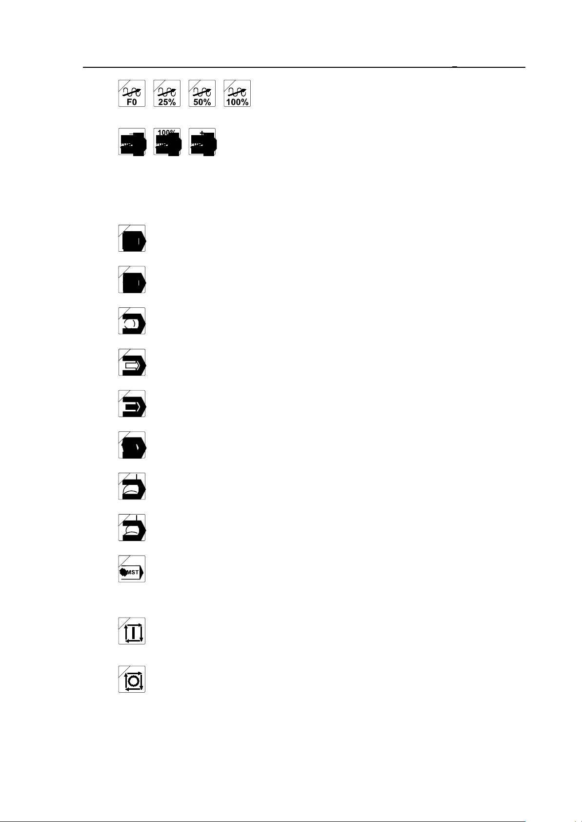
Optional machine control board
15
1 Operator’s Panel
Below the operating items of machine control board delivered by NCT are described. The
lighting state of LED in the top left corner of buttons shows, that the function indicated by the
key is active.
Emergency stop. By its depressing the NC registers the emergency stop state,
shuts down all movements, and cuts its outputs off the machine. It can be
undone by rotating the head of the button in the direction of the arrow. For more
details of its functioning turn to the machine tool builder for an information
material.
Machine on button. By affecting it, if the machine is not in emergency stop state (e.g.
the emergency stop is not in held down state) the control and the machine link. Other
parts of the machine, e.g., hydraulics, etc. come into effect. For more details about the
power-on process of the machine turn to the machine tool builder.
Operation mode selectors:
J og
Incremental jog
Manual handle
Manual reference point return
Edit
Automatic
Manual data input
Increment selectors:
Override switches:
Selecting 1, 10, 100, 1000 increment size.
Feedrate override switch. By affecting it the programmed feedrate
can be changed in the 0-120% range.
16
Rapid traverse override value can be influenced by
four optionally supplied buttons.
Spindle speed override buttons. By affecting <–> the pro-
grammed revolution is reduced, by affecting <+> it is increased
by 10% in the 50-150% range. As the effect of button 100% the
programmed revolution is acknowledged.
Switches modifying the conditions of program execution:
Single block execution
Conditional block skip
Conditional stop
1 Operator’s Panel
Program test
Machine lock
Dry run
Block restart
Block return
Function lock
Movement, start and stop buttons
Start button. Details of its functioning are discussed in the forthcoming
chapters of the Manual.
Stop button. Details of its functioning are discussed in the forthcoming
chapters of the Manual.
17

1 Operator’s Panel
Jog buttons. Operators of jogging and incrementing. In case of
running to reference point they serve for selecting axes. The
arrangement of buttons can vary for machine types.
Spindle start and stop buttons. By affecting them the spindle
starts to spin in CW direction (M3), or in CCW direction (M4),
as well as stops to spin (M5).
Apart from these buttons the machine control panel of NCT101, NCT104 contains 8
optionally used buttons equipped with LEDs (with 4 optional rapid traverse override
buttons among them), about which the machine tool builder decides, what function he chooses
to build in. Also, a manual handle can be attached to the machine control panel of NCT101,
NCT104.
18
2 General Operating Knowledge
2 General Operating Knowledge
2.1 Screen Menu
After turning the power on among the captions interpreting the softkeys the screen menu is
active. On a color screen the default background color of the menu bar of the screen menu is
light grey. In order to switch over from another menu to this, the screen menu key must
be pressed. The different screens can be selected in the screen menu by pressing the softkey
with the appropriate caption. Actions (e.g., Data input) cannot be initiated from the screen
menu, this menu is only for to switch over between screens. The screen menu is of two levels,
in the first level the following screen menus can be found:
Position
Check2Program
1
3
Offsets4Graphic
s5
Setting6Service
7 8 9
Page
1 0
If the appropriate screen within the screen menu is active, the caption of the menu field is
highlighted, otherwise the caption is dark (black). After turning the power on the ABSOLUTE
POSITION screen is active, this is why the Position (Positn) is highlighted. In order to switch
over to another screen menu simply the softkey of the desired screen menu must be pressed.
The last softkey of the first level of screen menu (beside the action menu key ) is the
Page. With this softkey can the next screen be switched over within the screen menu without
activating the menu by pushing the softkey of the active screen menu.
The control memorizes the screen within the screen menu, and when returning to the screen
menu it offers the same screen. For example if on the POSITION screen menu the MACHINE
POSITION is displayed by means of Page, than after selecting PROGRAM screen menu
POSITION screen menu is returned, in this case the MACHINE POSITION screen appears
(the name of the screen can always be seen in the third line).
Should the control contain other than ten, e.g. five softkeys, it can only display five menu
fields at a time. In this case the first level of the screen menu is as follows:
Position
Check
1
Program3Offsets4Page
2
5
Note, that the fifth softkey is the Page!
The part containing the further screen menus can be displayed by pressing screen menu key
:
Graphics1Setting
Service
2
3 4
Page
5
Here the caption of neither screen menu is highlighted, for the POSITION screen menu is
active, but presently it is not shown. As the last screen menu is the SERVICE, by pressing
screen menu key again the previous part of the screen menu is returned. If there were
19
2 General Operating Knowledge
further items after Service screen menu, those would be shown by pressing the screen menu
key , until the first part of screen menu is returned.
The number seen in the bottom right corner of menu field indicates the softkey number of the
appropriate menu field and not the line number of the menu within the screen menu (for more
see parameter SFNUMB ).
By pressing the softkey of the active screen menu, its menu appears. On the basis of the
previous example the following menu appears by pressing the Position softkey:
Absolute1Relative2Machine3End
Overall
4
5
The Position menu consists of five items, therefore starting with the sixth menu field the
forthcoming ones stay blank (for those have no meanings at all).
Suppose, that the second - and last - level of the screen menu is in effect. Here by pressing
the softkeys the caption of the appropriate menu field becomes highlighted and the selected
screen appears immediately. On the second level there is no Page softkey, because there the
desired screen can instantly be selected. If there is not enough room for the screens forming a
screen menu in the menu bar, the subsequent parts can be brought in by pressing the screen
menu key . If the last menu item of the screen menu is already in the menu bar, then by
pressing screen menu key the first level of the screen menu is returned.
Other than the use of page and softkeys, screen menu groups can be directly reached with the
help of the following page keys on NCT101, NCT104 keyboards:
paging to Position screen menu,
paging to Check screen menu,
paging to Program screen menu,
paging to Offsets screen menu,
paging to Graphic Position screen menu,
paging to Settings screen menu.
Immediately after pushing the appropriate key the screen menu belonging the that key can be
seen on the softkeys. The screen switches to the (inherited) display switched previously,
similarly to the case when the above result is reached by means of page key and
softkeys.
If the page key of a screen menu (e.g. ) is pushed once more, the given selection of
menus can be activated one by one, while the screen switches to the appropriate display.
20
2 General Operating Knowledge
The following menu items (screens) can be selected from the screen menus:
Position
Absolute1Relative2Machine3End
Overall5Cartesia
4
n6
7 8 9 0
Check
Text
Function2Last
1
Active4Oprtr`s
3
panel 5
Messag
e6
7 8 9 0
Program
Director
y1
View
2
Edit 3Block
input 4
FEW
5 6 7 8 9 0
Offsets
Work
offsets 1
Tool
offsets 2
W. offs.
measur 3
T. leng.
measur 4
Rel. pos
offsets 5
6 7 8 9 0
Graphics
Graphic
param 1
Draw
2 3 4 5
6
7 8 9 0
Setting
#1-
#33 1
#100#199 2
#500#599 3
Timer /
counter4
Tool pot 5PLC ta-
ble 6
User’s
params7
Security
8
9 0
Service
Param 1PLC 2Test
I/O 3
Logic
anal 4
Test
mes 5
Scope 6Errors 7Version
8 9 0
Summary: The screen menus are in two levels. The first level has eight screen menus. On the
first level the screens can be switched over within the active menu field by means of
Page softkey. If all menu items do not have enough room on the screen, the screen
menu key turns a page. If the last menu item is shown in the menu bar, then by
pressing screen menu key again, the first part of the first level is returned.
L Note:
Service screen menu cannot be reached directly by means of dedicated page key.
21
2 General Operating Knowledge
2.2 Action Menu
If some kind of action e.g., data input is to be done on different screens, the action menu
belonging to the screen can be switched over in the menu bar by pressing action menu key
. As could the screen menu, the action menu can also have maximum two levels, but in
some cases there are menu items already on the first level, that result in direct action.
The default background color of the action menu is orange. The active state of menu field may
also be indicated apart from the highlighted (white) or dark (black) colors of the caption by
the depressed state of menu field. If an action cannot be activated in the given control state,
the background color of menu field changes to the color of the screen menu and the menu
field serves no longer as a start button and is only surrounded by a frame.
If all action menu items belonging to the given screen do not have enough room in the menu
bar, then - as in case of screen menu - it is possible to turn the page within the menu by means
of action menu key . If the last menu is already on screen, then by pressing action
menu key the first part of the first level of the action menu is returned.
The action menu is determined by the active screen.
2.3 Data Input
On the different screens data input can be initiated. Data input must be started by pressing
action menu key The data input line is on the bottom of screen, above the softkeys is
the data input line, where the control gathers the entered data.
Numbers are entered according to the following rules:
– The number entered gives value to the address defined in the data input line.
– It is not mandatory to enter the left-hand (insignificant) zeros.
– The digit entered is interpreted as an integer or as a decimal digit before or after the decimal
point has been pressed, respectively.
– It is not necessary to enter the right-hand insignificant zeros behind the decimal point or the
decimal point (in the case of an integer value).
– The data input can be started with decimal point when the integer part of a number is zero.
– Key , or and incremental operator I (provided they are permissible for the given
address character) may be hit several times during the input of the number, any time
before the use of arrow keys terminating the numeric input. The default is a positive
absolute value. The incremental data input and the sign will be indicated in the first
and second positions of the location in front of the number, respectively.
– The control system displays DATA error message during data input whenever a formal error
is committed in the number to be specified for the given address (exceeding the
number of integer or decimal digits, illegal use of the incremental operator or one of
22
keys , or , .

2 General Operating Knowledge
– A numeric input in progress can be cleared any time by key <DEL> before termina-
tion. In this case the condition preceding the commencement of numeric input is
restored.
The effects of keys and terminating a numeric input differ from each other in that
forward or backward stepping in the address chain will be performed upon depression of
or , respectively. Keys and can be used for stepping the address
chain (in the absence of a numeric input) as well as for the termination of a numeric input.
23

3 General Displaying Areas and Actions Executed on Them
3 General Displaying Areas and Actions Executed on Them
Each general displaying area is accessible any time, independent of the current operation
mode or other states of control.
However actions belonging to the given display cannot be executed any time, the execution
can depend on the mode or other states of control. For example editing of parameters can only
be done in EDIT mode, although the list of parameters can be seen any time, in AUTOMATIC mode even during machining . If execution of an action is impossible in the given
control mode, it is indicated by two arrows pointing at each other º» (conflicting state) in
the status field of the seventh message line.
It is quite another matter, that the action may be able to be executed in any control mode, still
the action will not be effective immediately. For example the tool offset value can be changed
any time, even during milling, yet the machining must be interrupted (create INTD state) and
restarted for the control to register the new offset value.
24

3.1 Turn-on Process of the Control
3.1 Turn-on Process of the Control
During operation control receives the codes needed for the operation, the values of
parameters influencing its operation, as well as the PLC program that fits it to the given
machine from DRAM. The DRAM content is deleted when it is switched off, therefore the
DRAM contents must be loaded from non-volatile memories when it is switched on.
The data entered by the user are also stored in non-volatile memories, like part programs,
work offsets, tool compensations, macro variables (#500...#599), counters, as well as PLC
flags signaling the machine operation state.
The turn-on process indicates check of these memories.
3.1.1 First Phase of the Turn-on Process and its Error Messages
After turn-on the control first executes self-diagnostics, it checks the checksum of the codes in
appropriate memories as well as of the parameters, than it loads the DRAMs.
If it finds error
SYSTEM,
HGSZ,
PLC,
PARAMS
in one of the codes, the turn-on process stops. If no error is found, it sends OK messages after
the above entries, in case error is found, BAD message appears.
LWarning: If the NC stops because of an error in course of the above check, always turn
to expert service!
3.1.2 Second Phase of the Turn-on Process and its Error Messages
If the parameters are also found correct by the control, the second phase of turn-on process
begins. In course of this ABSOLUTE POSITION screen appears. It checks the following data
during turn-on process:
– It checks the checksum of PLC flags and tables describing the machine state. If it finds
error, it sends message
TOOL PLACE TABLE BAD No. 3504
L Warning! After deleting the above error message these flags and tables must be set
according to the machine state. Its omission may cause injury, or perhaps machine
deterioration, therefore in such cases turn to the machine tool builder for help, or
read the supplementary manuals and follow their instructions.
– It checks the checksum of the volatile memory area containing NC state. These data are as
follows:
G20/G21: inch/metric size setting,
Length compensation setting,
The program, the execution of which was interrupted, if turn-off was activated during
program execution, in order to initiate search for the interrupted block,
Graphic screen settings.
If error is found, it send error message
NC STATUS TABLE BAD No. 3508
.
25

3.1 Turn-on Process of the Control
L Warning! After deleting the above error message the operator’s thoughtful intervention is
needed.
– It checks the checksum of the tool compensation table. If error is found, it sends error
message
TOOL OFFSET TABLE BAD No. 3510
L Warning! After deleting the above error message the tool compensations must be re-
measured, otherwise any program start may cause injury, or perhaps machine
deterioration.
– It checks the checksum of work offset table. If error is found, it sends error message
WORK OFFSET TABLE BAD No. 3511
L Warning! After deleting the above error message the work offsets must be re-measured,
otherwise any program start may cause injury, or perhaps machine deterioration.
– It checks the checksum of volatile macro variables #500, ..., #599. If error is found, it
sends error message
MACRO TABLE BAD No. 3545
L Warning! The above variables may contain important data to be kept, which influence
machine operation. These may be measure cycle parameters, tool replacement state
etc. After deleting the above error message the registers must be set according to the
machine state. Its omission may cause injury, or perhaps machine deterioration,
therefore in such cases turn to the machine tool builder for help, or read the
supplementary manuals and follow their instructions.
The above error messages can be deleted by key (reset). In this case the data belonging
to the message will be set to 0, except for macro variables #500, ..., #599, the value of which
will be vacant.
26
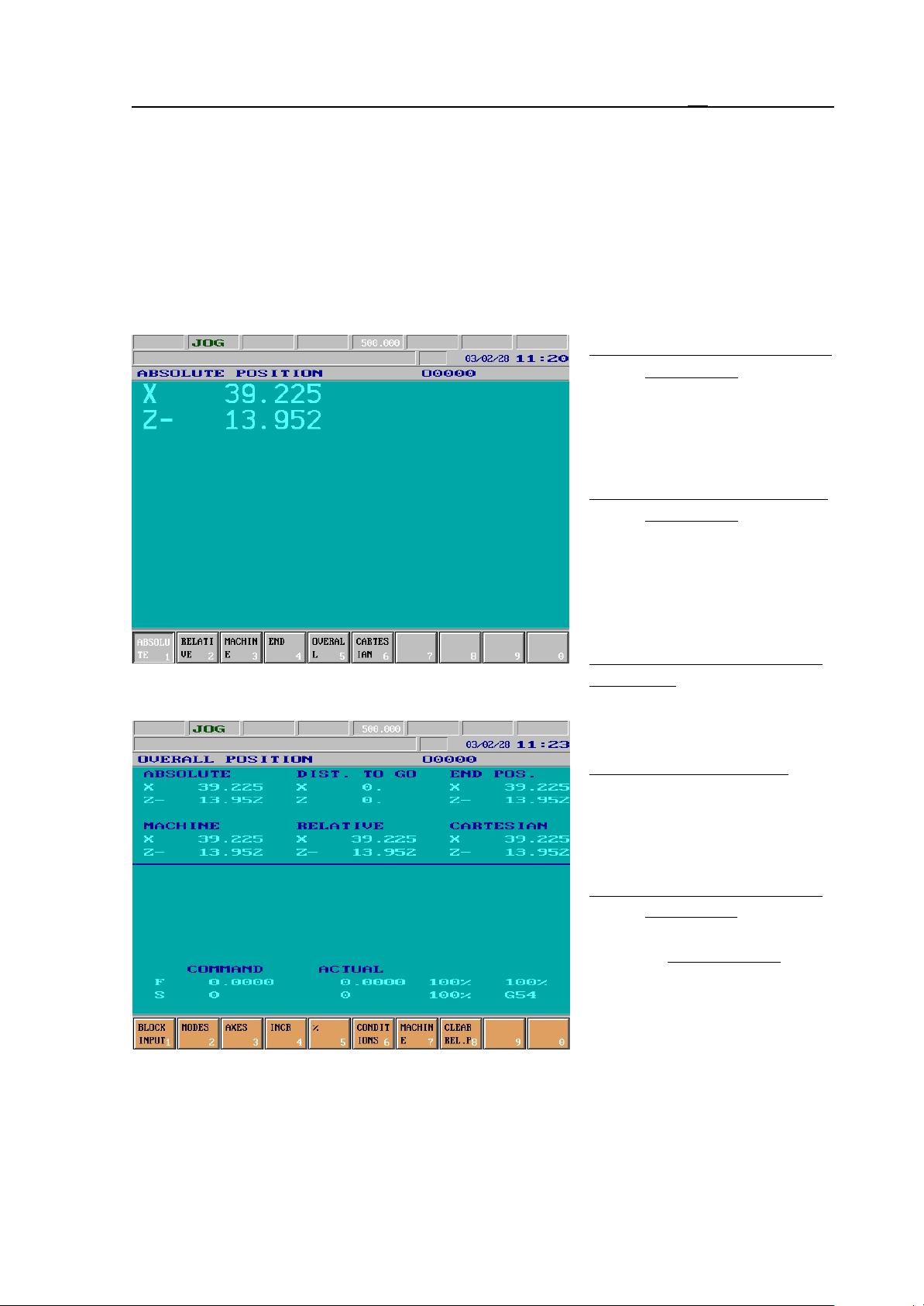
3.2 POSITION Screens
3.2 POSITION Screens
There can be five types of POSITION screens. The first four screens displays the selected
position with big-size characters, meanwhile on the fifth screen all position displays as well as
in case of six or fewer axes the feed and revolution values are also displayed with normal
characters. In case of an oriented spindle when the loop is closed (state M19) the screen shows
the angle position of the spindle instead of the revolution. If the spindle can be programmed as
axis C, the line starts with C in place of S. In the line of feed display the current coordinate
system number can also be read.
ABSOLUTE POSITION Scre-
en (Absolt): In the
selected coordinate
system in respect of the
appropriate offsets and
compensations.
RELATIVE POSITION Scre-
en (Relatv): After refer-
ence point has been returned it corresponds to
absolute position. It can
be overwritten or zeroed
in an optional state.
in the G53 coordinate system in respect of length offsets.
MACHINE POSITION Screen (Mach): Position measured
END POSITION Screen: End
position of the block in
the current coordinate
system in respect of
length offsets.
OVERALL POSITION Scre-
en (Overll): Beside the
previous four displays
the distance to go also
gets to be displayed. It
shows how much is left
of the current movement.
By this display (in case
of six or fewer axes) the
programmed and current
feed and revolution can
also be seen.
27

3.2 POSITION Screens
CARTESIAN POSITION Screen: In the state of polar coordinate interpolation on (G12.1) it
indicates the tool position in the programmed Cartesian coordinate system. In the state
of polar coordinate interpolation off (G13.1) positions indicated here are the same as
on the screen ABSOLUTE.
The first three screens also have a setting function; The position display selected the last time
will be beside distance to go and end position by general displaying areas (except for offsets),
where the position display can be seen on the top of general displaying area.
Actions of POSITION Screens
Actions of POSITION screens correspond to that of the OPERATOR’S PANEL screen (see
the chapter 3.3.4) .
28
3.3 CHECK Screens
3.3 CHECK Screens
This screen serves for displaying running programs and their states.
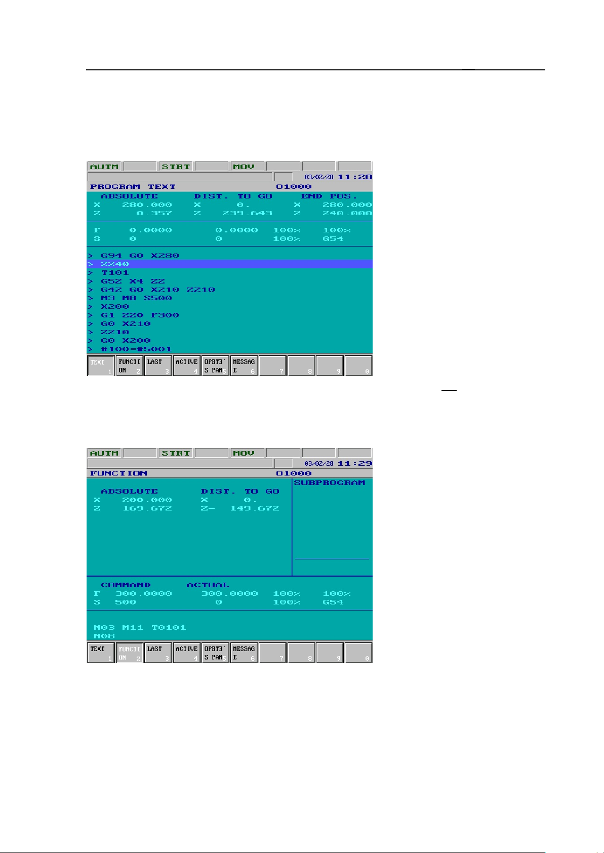
3.3.1 PROGRAM TEXT Screen, Listing of Running Program
In the lower part of general displaying area the list of the running program can be seen. One
block on the list is highlighted;
This is the block under execution. In the middle part of general displaying areas of feed and
revolution can be seen (provided
the number of displayed axes is
not more than six). The position
display is in the upper part of
general displaying area. In the
first column the current tool position in agreement with the selected POSITION screen (see
the chapter 3.2), in the middle
column the distance to go position, while in the right one the end position can be seen.
3.3.2 FUNCTION Screen, Subprogram and Macro Levels
In the right-side subprogram
field of general displaying area
the active subprogram(s) can be
seen. Directly after the number
of the subprogram stands the
repetition number. The fields on
the bottom of general displaying
area show information on the
revolution state of spindle (M3,
M4, M5, M19), of the gear
range (M11, M12, M113,
M14,...), of the current tool
(Tnnnn), of auxiliary functions
(A, B and C), as well as of
further (in PLC program
defined) M codes.
The first column shows the position in agreement with the selected POSITION screen (see
the chapter 3.2), while the second one shows the distance to go position.
29
3.3 CHECK Screens
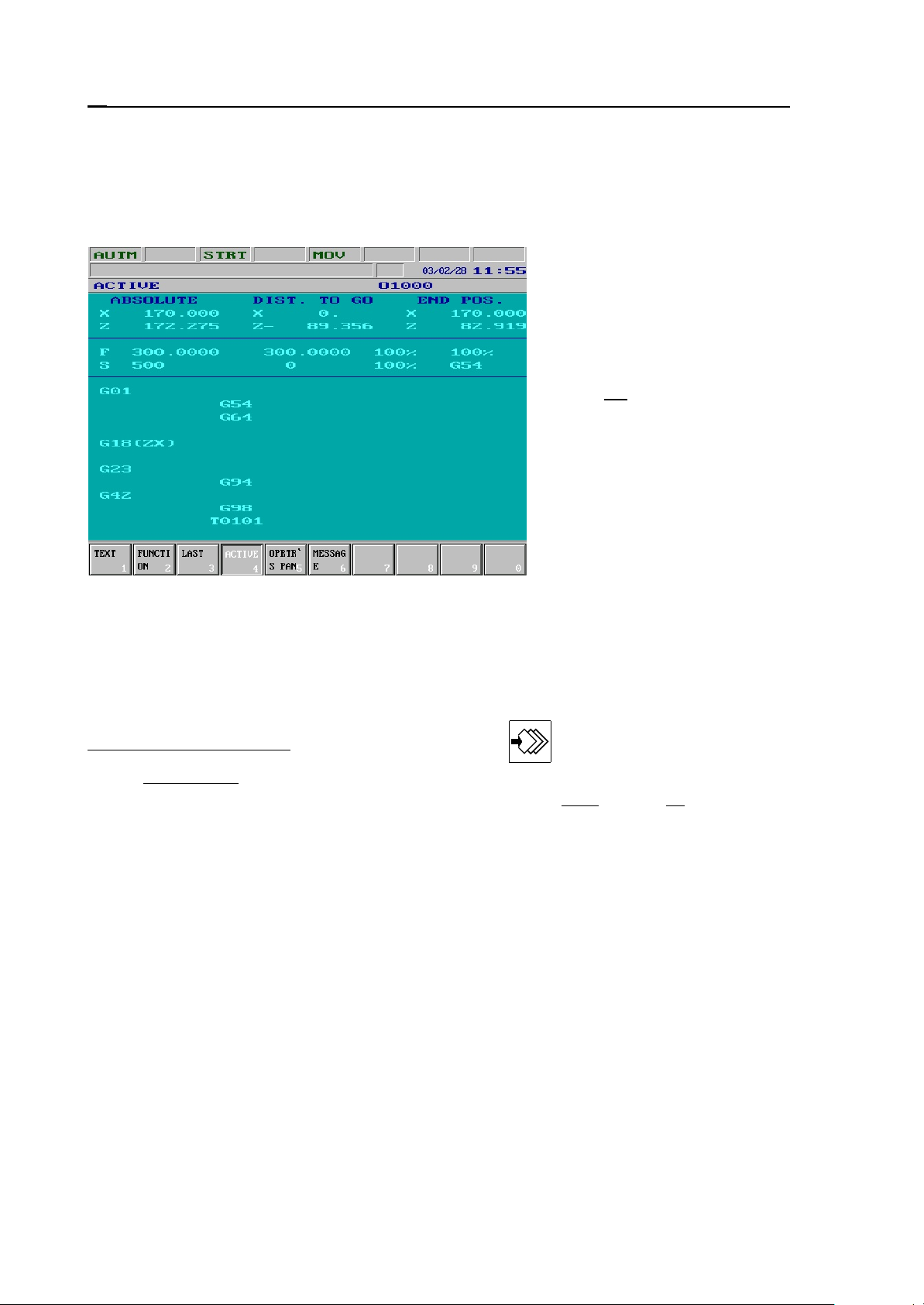
3.3.3 LAST and ACTIVE screens. G Codes and Compensations.
On the LAST and ACTIVE screens the active G codes and compensations under block
display (LAST) and program execution (ACTIVE) can be seen. The LAST screen corresponds
to the values of #4000..., #4100... macro variables, while the ACTIVE screen to that of
#4200..., #4300... .
The current tool position is
displayed on the upper part of
general displaying area. In the
first column the position in
agreement with the selected
POSITION screen (see the
chapter 3.2), in the middle
column the distance to go
position, while in the right one
the end position can be seen.
If less than seven axes are to be
displayed information on feed
and spindle revolution appears
in the middle part of general
displaying area.
In the lower part of general
displaying area starting from the left, downwards the G codes and the tool number with the
compensation number can be seen.
Of the G codes only those, different from default setting are displayed.
Actions of sreens PROGRAM TEXT, FUNCTION, LAST and ACTIVE.
Block Input action menu: Pushing action menu button and selecting action menu
Block Input, it is possible to input and execute a program block or to modify an old
one. For detailed description of the function see chapter 3.4.4 on page 36.
30
 Loading...