

1
VISM Evolution Scope Series
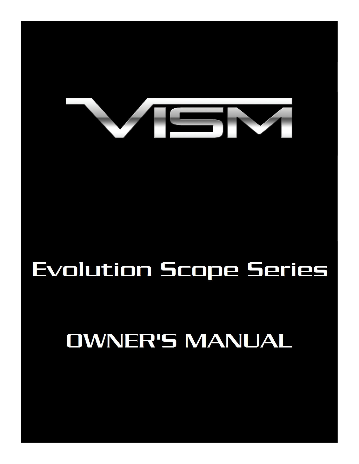
A. Ocular Lens
B. Quick Focus Ring
C. Rheostat Knob
D. Magnification Ring
E. Elevation Adjustment Dial
F. Windage Adjustment Dial
G. Parallax Adjustment Dial
H. Objective Lens
Congratulations on the purchase of your New VISM Evolution (EVO) Series Scope! The EVO Series
of Scopes give you many great high end features and various magnification ranges so you can select an
EVO model that best fits your needs. Backed by a Lifetime Limited Warranty, your VISM Scope will
provide you with years of reliable service. This Owner’s Manual will help you understand all of the features
of your new scope. Follow all instructions carefully before initial use to experience the best performance.
CAUTION: BE SURE THAT YOUR FIREARM IS UNLOADED AND POINTED IN A SAFE DIRECTION.
PRACTICE SAFE FIREARMS HANDLING PROCEDURES AT ALL TIMES.
NOTE: IF YOU ARE UNFAMILIAR WITH THE PROCESS OF MOUNTING A SCOPE, IT MAY BE
NECESSARY TO EMPLOY THE SERVICE OF A QUALIFIED GUNSMITH.
Choosing a proper ring type and height is essential to successfully mounting this scope to your
firearm. Be sure to follow the Manufacturers Installation Instructions of the scope rings and base that you
choose.
Mounting your scope as low as possible on the firearm will help to achieve optimum cheek weld and
a comfortable, consistent shooting position. Use the lowest rings possible while ensuring that no part of the
scope is in contact with any part of the firearm. Also, be sure that you can operate all features of the scope,
and that all parts of the firearm function normally without interference from the scope.
Once you have the scope mounted in the rings (before final tightening) it is necessary to adjust the
scope’s position to allow for Maximum Eye Relief and reticle leveling. Slide the scope as far forward as
possible in the rings. While viewing through the scope in a normal shooting position move the scope back
towards your eye until a Full Field of View is achieved while ensuring that the scope will be a safe distance
from your eye when the firearm recoils. Without disturbing the Eye Relief setting, aim the reticle at a
plumb line. Align the vertical cross hair of the reticle with the plumb line by rotating the scope within the
rings. Once you are satisfied with your scopes setting and placement, tighten the rings evenly and securely
according to the Manufactures Specifications. Be sure not to over tighten the rings, as doing so can cause
permanent damage to the scope.
EVO Series Features
Mounting Your Scope
2
Your VISM Scope is factory set with a Centered Reticle necessary for efficient sighting-in. If you
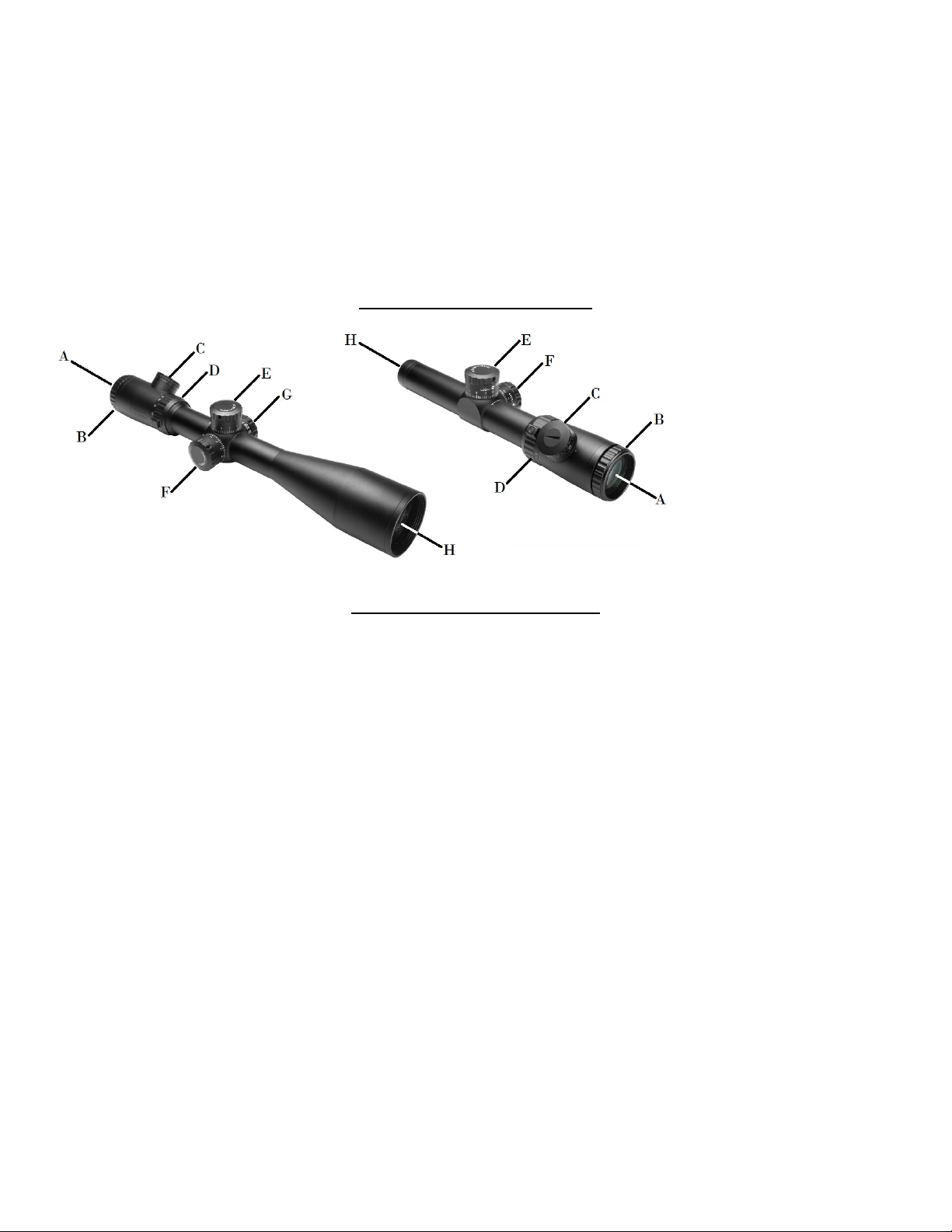
B. Quick Focus Ring
have made any prior adjustments to the Elevation and Windage settings it will be necessary to re-center
the reticle. Turn the Elevation Adjustment Dial in either direction until it comes to a complete stop. Next,
turn the dial in the opposite direction, counting the number of clicks, until you have reached the limits of
the adjustment range. Divide the number of clicks in half, and turn the dial that exact number of clicks
back towards the center of the adjustment range. Repeat this procedure for the Windage Adjustment Dial.
The reticle is now centered.
CAUTION: VIEWING THE SUN WITH THIS SCOPE OR ANY OTHER OPTICAL DEVICE CAN CAUSE
PERMANENT INJURY TO THE EYE INCLUDING BLINDNESS
Holding the scope at the proper distance from your eye, in order to achieve a Full Field of View, the
reticle should appear sharp and clear. If not, it will be necessary to adjust the focus by turning the Quick
Focus Ring.
1. Make quick glances through the eyepiece at a featureless bright surface such
as a white wall, or the open sky.
2. Turning the Quick Focus Ring counter-clockwise () will extend the Ocular
Lens outward, generally suitable for those who are far sighted. Turning the
Quick Focus Ring clockwise () will draw the Ocular Lens inward, generally
suitable for those who are near sighted.
3. Fine tune your adjustments until the reticle appears sharp and clear. Once
the Ocular Lens reaches its outer limits of adjustment, be sure not to force it
as doing so will cause damage to the eyepiece.
Magnification Adjustment
The EVO Scopes have a Magnification Power selector ring located directly in front of the eyepiece.
By turning this ring you can quickly and easily choose the desired magnification level. Lower levels of
magnification provide you with a wider Field of View, while higher levels of magnification provide you with
a closer view of your target.
CAUTION: DO NOT ATTEMPT TO LOOSEN OR REMOVE THE SLOTTED SCREW ON THE
MAGNIFICATION RING. DOING SO CAN RELEASE THE INTERNAL NITROGEN GAS CAUSING
DAMAGE TO THE SCOPE.
Focusing Your Scope
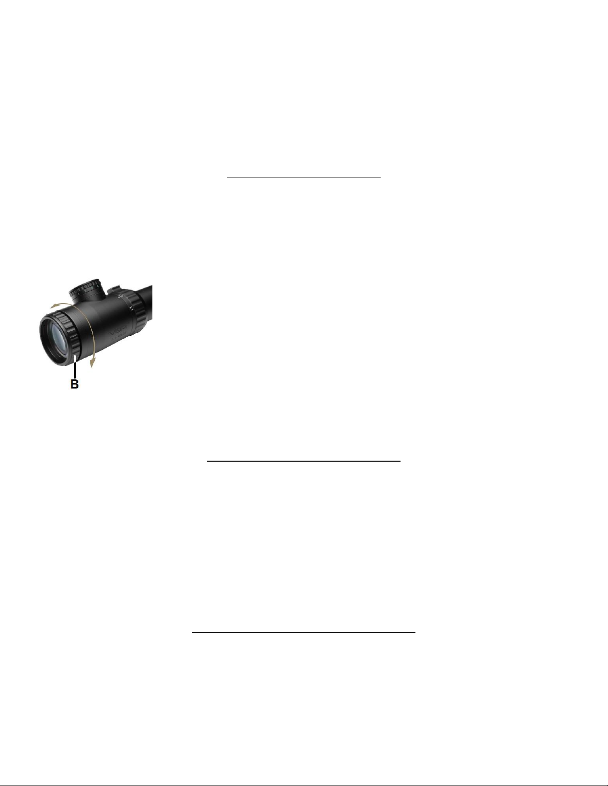
On a few select EVO scope models will have a side Parallax Adjustment Dial feature. If your scope
is equipped with a side Parallax Adjustment feature, there will be a third turret dial on the left side of the
scope body, along with the elevation and windage turrets. The Parallax Adjustment Dial will fine tune the
parallax alignment of the scope, so that you can properly adjust the parallax of your reticle to the target
image in the scope.
Side Parallax Adjustment Dial
3

If you do not have the parallax adjust properly, if you were to move your eye around the ocular
G. Parallax Adjustment Dial
E. Elevation Adjustment Dial
F. Windage Adjustment Dial
lens, the reticle will seem to move in relations to the target image.
Have the scope on a stable platform, while viewing your target through
the scope. Adjust the Parallax Adjustment Dial in either direction until the
reticle stays perfectly still on your target, if you were to move your eye around
the ocular lens while viewing through the scope. With the reticle properly
adjusted, the reticle should remain still on your target (as if the reticle was
painted onto the target). Adjusting the parallax so that the reticle is stationary
against the target image will help the shooter make a more precise shot at
longer distances and help with shooting a more consistent and tighter shot
groupings.
Windage and Elevation Adjustment Dials
Your scope is equipped with Elevation and Windage Adjustment Dials, which change your scopes
point of aim relative to the bullet’s point of impact on a target for a specific range. The Elevation
Adjustment Dial is located on top of the Turret Body, and is responsible for the up and down movement of
the reticle. The Windage Adjustment Dial is located on the right side of the Turret Body, and is responsible
for the left and right movement of the of the reticle.
The EVO series of scopes are equipped with Lockable Adjustment Dials. When the bottom edge of
the Adjustment Dial is flush with the scope body, it is in the Locked position. When the bottom edge of the
Adjustment Dial is about ⅛” away from the scope body, it is in the Unlocked position.
To Unlock the Adjustment Dials, you only have to gently pull the
Adjustment Dial away from the scope body. You will feel the dial move
outwardly by approximately ⅛” away from the scope body when it is in the
Unlocked position. You will now be able to rotate the Adjustment Dials in
either direction to adjust the reticle. When you have finished making your
adjustments to the reticle, you can then press the Adjustment Dials towards
the scope body to Lock the Adjustment Dial in place. You will feel the
Adjustment Dial move inwards flush with the scope body.
On the surface of the scope body next to each Adjustment Dials you
will notice that there are arrows indicating direction of movement.
Turning the Elevation Adjustment Dial counter-clockwise () will shift the bullet point of impact up ().
Turning the Elevation Adjustment Dial clockwise () will shift the bullet point of impact down ().
Turning the Windage Adjustment Dial counter-clockwise () will shift the bullet point of impact right ().
Turning the Elevation Adjustment Dial clockwise () will shift the bullet point of impact left ().
The Elevation and Windage Adjustment Dials also feature Audible and Tactile Clicks which not
only can you see and hear the adjustments, but you can feel them as well. Depending on which EVO scope
you have, each Click moves the reticle point of aim a certain amount MOA* at 100 Yards. See the chart
4

below to see the amount of movement of each click of the Adjustment Dials will move the reticle for your
Elevation/Windage movement per click
Magnification Model
100 yards
200 yards
300 yards
400 yards
500 yards
6-24 X 50mm
⅛ MOA
¼ MOA
⅜ MOA
½ MOA
⅝ MOA
4 – 16 X 50mm
⅛ MOA
¼ MOA
⅜ MOA
½ MOA
⅝ MOA
2.5 – 10 X 50mm
¼ MOA
½ MOA
¾ MOA
1 MOA
1¼ MOA
1.1 – 4 X 24mm
½ MOA
1 MOA
1½ MOA
2 MOA
2½ MOA
specific EVO scope model at various distances.
*1 MOA = 1.047 Inches at 100 Yards
The Adjustment Dials can be re-indexed after you get the scope zeroed. You can re-index the Dial’s
“0” markings to the indicator marks on the scope body. On the top edge knurling of the Dials, you’ll find
three 2mm Allen Set Screws. If you loosen all three set screws, you will be able to rotate the outer Dial,
without moving the internal reticle adjustment mechanism. Once you have the outer Dial’s “0” markings
indexed to the markings on the scope body, you can re-tighten the three Allen set screws to tighten the
outer Dial to the internal reticle adjustment mechanism.
Zeroing your Scope
After you have completed installation of your scope it will be necessary to adjust the scopes point of
aim to match the rifles point of impact on a target. This can be accomplished using several methods, but
we recommend the use of a Bore Sighting Device to save time and ammunition. Using a Bore Sighting
Device will ensure that your shots land “on paper”. Follow the Manufacturer’s Instructions for the Bore
Sighting Device that you choose in order to achieve the best results. You are now ready to finalize your
Zero.
CAUTION: ALWAYS BE SURE TO REMOVE THE BORE SIGHTING DEVICE BEFORE SHOOTING LIVE
AMMUNITION. FAILURE TO DO SO CAN CAUSE DAMAGE TO YOUR FIREARM OR INJURY TO
YOURSELF AND THOSE AROUND YOU.
CAUTION: WHEN OPERATING ANY TYPE OF FIREARM ALWAYS USE PROPER EYE AND EAR
PROTECTION. BE SURE TO USE YOUR FIREARM IN AN AREA THAT IS PERMISSIBLE UNDER
LOCAL, STATE, AND FEDERAL LAW.
Bore Sighting alone is not sufficient enough to ensure and accurate Zero. You must shoot your firearm
at the range in order to confirm an accurate Zero. Follow these steps to fine tune your scope adjustments:
1. Secure your firearm using a steady platform such as a rifle bench rest or sand bags.
2. Fire 3 to 5 carefully aimed shots at a target that is set to your desired Zeroing distance (100 yards is
recommended).
3. Observe where the bullet grouping have struck the target and make adjustments to the Elevation
and Windage settings as necessary until your point of aim matches your point of impact.
4. Continue with this process until you have achieved your desired level of accuracy.
5. Your scope is now Zeroed to your firearm at the distance that you have chosen.
5

It is important to remember that many factors can affect the accuracy of your scopes zero including
I. Battery Cap
J. CR2032 Battery
C. Rheostat Knob
temperature, humidity, elevation, distance, angle, and other conditions. Changing ammunition brands can
affect accuracy as well.
Battery Installation
Your Illuminated Model EVO Series Scope comes with a battery pre-installed from
the factory. To replace the battery follow these simple steps:
1. The Battery Compartment is located within the Rheostat Dial on top of the Ocular
Lens Housing.
2. On top of the Rheostat Dial you will notice a thin Battery Cap. To remove this cap
grasp it firmly with one hand, and twist the cap counter-clockwise () while holding
the lower Rheostat Dial firmly in place with the other hand.
3. Remove the old battery, and dispose of it properly. Replace it with a new 3 volt
Lithium Battery Type CR2032 only. Place the Battery into the Battery compartment
with the Positive “+” terminal facing out. Place the battery cap back on top of the
Rheostat Dial. Twist the battery cap clockwise () back onto the Rheostat Dial and
hand tighten. Avoid using tools (such as pliers) to perform this procedure as this may
cause damage to the unit.
Illuminated Reticle
Your EVO Series Scope is equipped with a Glass Etched Reticle that can be illuminated in 2
different colors (Blue or Green) for use when exterior lighting conditions are less than optimal. A Glass
Etched Reticle has a finer detailed reticle and is more durable than your typical wire reticle used in the
majority of other scopes.
The Rheostat Dial is oriented at a 45 degree angle from the scope
centerline on ocular lens housing, to provide the shooter an unobstructed view
of the elevation turret markings. Control of the illumination is achieved by
simply rotating the Rheostat Dial in one direction or the other.
numbers. “0” represents the Off position. If you turn the Dial in either
direction the reticle will illuminate blue or green (depending upon the direction
that it is turned). Each illumination color can be set to 5 levels of intensity, “1”
being the dimmest and “5” being the brightest. Adjust the brightness level as needed in accordance with
the surrounding conditions. The illumination will increase reticle visibility especially during dawn and
dusk. This illuminated scope is not intended for use in total darkness. When the illumination is turned off
the reticle will appear as normal Black Reticle. Be sure that the Rheostat Dial is set to the “0” position
when not in use to preserve battery life.
If you look closely at the side of the Dial you will notice a series of
6

VEVOFD11424G DOT
VEVOFM11424G MIL-DOT
VEVOFP11424G P4 SNIPER
VEVOFD251050G DOT
VEVOFM251050G MIL-DOT
VEVOFP251050G P4 SNIPER
VEVOFD41650G DOT
VEVOFM41650G MIL-DOT
VEVOFP41650G P4 SNIPER
VEVOFD62450G DOT
VEVOFM62450G MIL-DOT
VEVOFP62450G P4 SNIPER
CLICK
VALUE
ITEM #
RETICLE
COLOR
MAGNIFICATION
TUBE DIA.
OBJECTIVE
DIA. (mm)
FOV (FEET @ 100
YARDS)
EYE RELIEF (in)
EXIT PUPIL (mm)
NET
WEIGHT
(oz.)
LENGTH
(in)
BLACK
1.1 - 4X
30 mm
24 mm
98.3 - 27.2
3.7 - 3.3
21.8 - 6
16.5
10
½ MOA
BLACK
2.5 - 10X
30 mm
50 mm
43.2 - 10.8
3.3 - 3.2
22.4 - 5.6
25.2
14.8
¼ MOA
BLACK
4 - 16X
30 mm
50 mm
27.2 - 6.8
4.8 - 3.3
12.5 - 3.1
25.3
14.2
⅛ MOA
BLACK
6 - 24X
30 mm
50 mm
18.0 - 4.5
3.5 - 3.3
8.3 - 2.1
25.2
15.4
⅛ MOA
Care and Maintenance
Your VISM EVO Series Scope is shock proof, fog proof, and waterproof. However, you should
never try to take it apart or clean it internally. The exposed optical lens surfaces will perform their best if
they are routinely cleaned with a lens brush or a lens cloth. For a deep cleaning, you can also use high
grade camera lens paper and camera lens cleaning solutions. Never use any other type of materials or
solvents other than those designed specifically for optical lenses to avoid damaging your scope. Clean the
outer portion of the lens cavity first with cotton swabs, clearing as much debris and dust as possible. Then,
gently clean the lenses using a circular motion starting in the center and ending at the edges. Do not rub
the lenses continually; simply wipe in short circular patterns. Maintain the exterior surfaces of the scope by
removing dirt or sand by using a soft brush or a soft, dry cloth. You can also use a silicone treated cloth to
restore luster and protect the scope against corrosion. Be careful not to touch any of the lenses with the
silicone cloth. It is not necessary to lubricate any part of the scope as all of the moving parts, such as the
turrets and the fast focus eyepiece, are permanently lubricated. When not in use, always store your scope
in a dry place with the lens caps on to prevent scratches to the lenses.
IF YOU ARE UNFAMILIAR WITH ANY OF THE PROCEDURES IN THIS MANUAL,
ALWAYS SEEK THE HELP OF A QUALIFIED PROFESSIONAL TO AVOID DAMAGE TO
YOUR SCOPE AND YOUR FIREARM.
VISM EVOLUTION Series Scope Specifications
7

8
 Loading...