

1
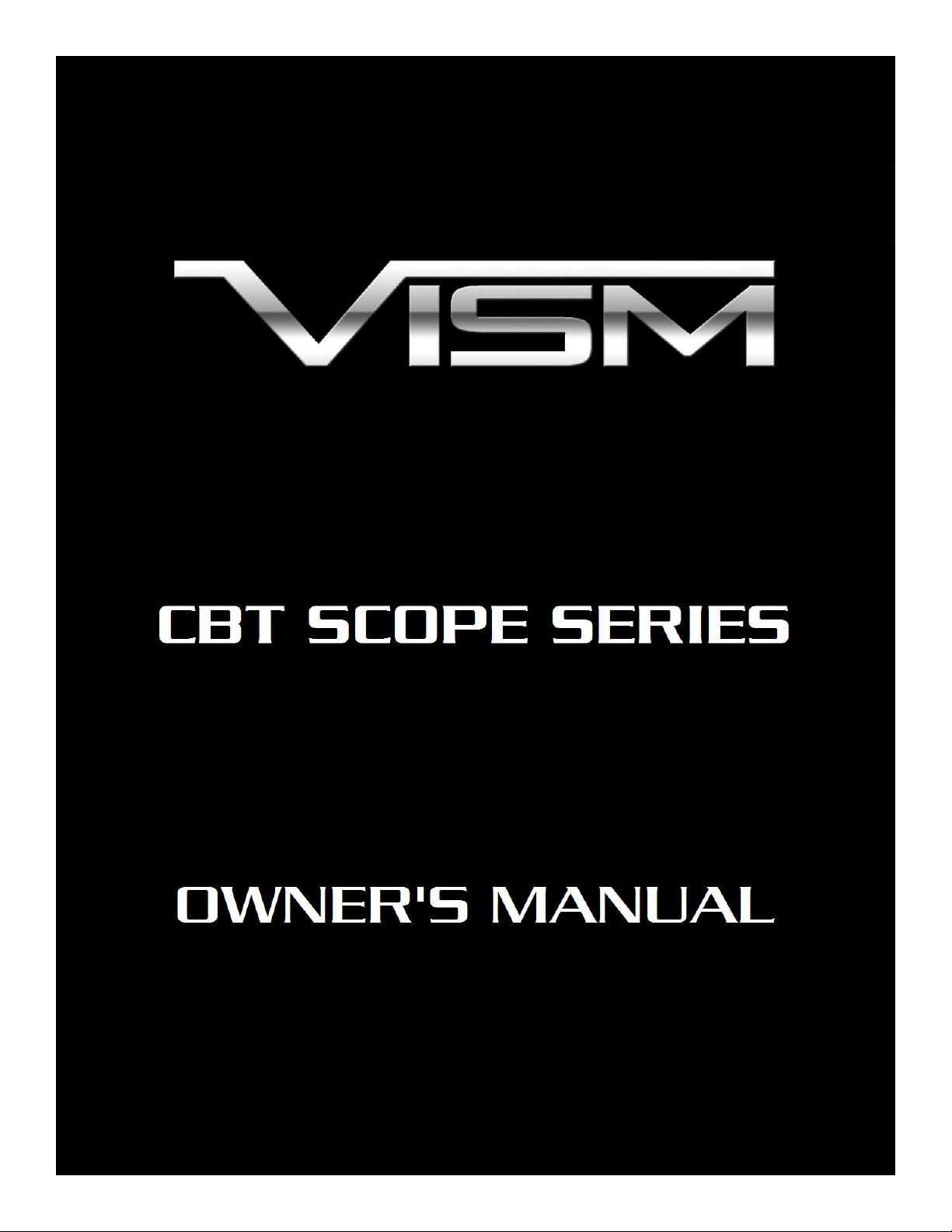
VISM CBT Scope Series with Integrated Red Laser
1. Ocular Lens
2. Quick Focus Ring
3. Elevation Adjustment Dial
4. Laser Elevation Adjustment
5. Laser Windage Adjustment
6. Objective Lens
7. Rheostat and Battery Compartment
8. Windage Adjustment Dial
9. Quick Release Lever
10. Auto-Locking Latch
11. Integrated Weaver/ Picatinny type Mount
12. Mount Recoil Lug
13. Lock Nut
14. Allen Head Adjustment Screw
Congratulations on the purchase of your new VISM CBT Scope! The CBT Series of Scopes give you
many great options so you can choose the scope that best fits your needs. Backed by a Lifetime Limited
Warranty, your VISM Scope will provide you with years of reliable service. This Owner’s Manual will help
you understand all of the features of your new scope. Follow all instructions carefully before initial use to
experience the best performance.
CBT Scope Series Features
CAUTION: BE SURE THAT YOUR FIREARM IS UNLOADED AND POINTED IN A SAFE DIRECTION.
PRACTICE SAFE FIREARMS HANDLING PROCEDURES AT ALL TIMES.
NOTE: IF YOU ARE UNFAMILIAR WITH THE PROCESS OF MOUNTING A SCOPE, IT MAY BE
NECESSARY TO EMPLOY THE SERVICE OF A QUALIFIED GUNSMITH.
Mounting Your CBT Scope
The CBT Scope is equipped with a Quick Release Mount with an Auto-Locking Latch. To attach the
CBT Scope to a Weaver/ Picatinny/ MIL-STD 1913 type rail, move the Auto-Locking Latch located within
the Quick Release Lever away from the pivot point and swing the Quick Release Lever to the forward
(Open) position. Place the Quick Release Mount onto the optics rail, with the Recoil Lug placed into one of
the cross slots on the optics rail. Move the Quick Release Lever rearward (Closed position) to secure/tighten
the Quick Release Mount to the optics rail.
On the Left side of the Quick Release Mount is a Lock Nut and Allen Head Adjustment Screw. The
Allen Head Adjustment Screw is used to adjust the rail mount tension. To adjust the rail mount tension,
2
you must first loosen the Lock Nut Counter-Clockwise (). Once the Lock Nut is loosened or removed, you
can then use an Allen wrench to turn the Allen Head Adjustment Screw.
Turn the Allen Head Adjustment Screw Clockwise () to make the rail mount tension Tighter, turn
the Allen Head Adjustment Screw Counter-Clockwise () to make the rail mount tension Looser.
To test the rail mount tension, open and close the Quick Release Lever while mounted on the optics
rail. Make adjustments to the Allen Head Adjustment Screw until you get the proper rail tension. Once you
have the rail mount tension properly adjusted, turn the Lock Nut Clockwise () to Lock the Allen Head
Adjustment Screw in place.
Focusing Your Scope
CAUTION: VIEWING THE SUN WITH THIS SCOPE OR ANY OTHER OPTICAL DEVICE CAN CAUSE
PERMANENT INJURY TO THE EYE; INCLUDING BLINDNESS.
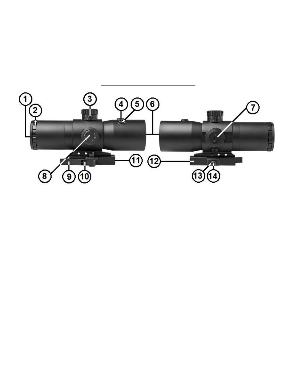
Holding the CBT Scope at the proper distance from your eye, in order to achieve a Full Field of View,
the reticle should appear sharp and clear. If not, it will be necessary to adjust the focus by turning the
Quick Focus Ring.
1. Make quick glances through the eyepiece at a featureless bright surface
such as a white wall, or the open sky.
2. Turning the Quick Focus Ring Counter-Clockwise () will extend the
Ocular Lens outward, generally suitable for those who are far sighted.
Turning the Quick Focus Ring Clockwise () will draw the Ocular
Lens inward, generally suitable for those who are near sighted.
3. Fine tune your adjustments until the reticle appears sharp and clear.
Once the Ocular Lens reaches its outer limits of adjustment, be sure
not to force it as doing so will cause damage to the eyepiece.
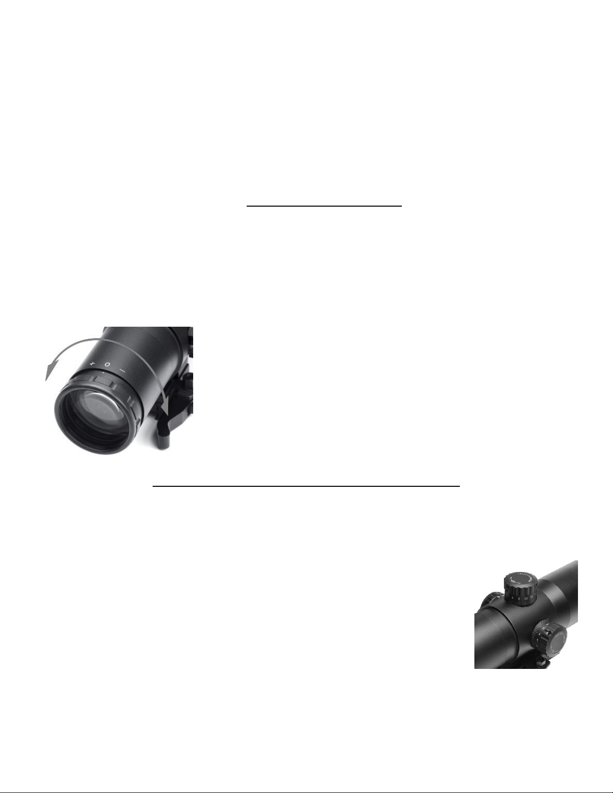
Windage and Elevation Adjustment Dials
Your CBT scope is equipped with Elevation and Windage Adjustment Dials, which changes your
reticles point of aim, relative to your rifles point of impact. The Elevation Adjustment Dial is located on
top of the Turret Body, and is responsible for the Up and Down movement of the reticle. The Windage
Adjustment Dial is located on the right side of the Turret Body, and is responsible for the Left and Right
movement of the of the reticle.
The CBT series of scopes are equipped with Lockable Adjustment Dials. When
the bottom edge of the Adjustment Dial is flush with the scope body, it is in the
Locked position. When the bottom edge of the Adjustment Dial is about ⅛” away
from the scope body, it is in the Unlocked position.
To Unlock the Adjustment Dials, you only have to gently pull the
Adjustment Dial away from the scope body. You will feel the dial move outwardly by approximately ⅛”
away from the scope body when it is in the Unlocked position. You will now be able to rotate the
Adjustment Dials in either direction to adjust the reticle. When you have finished making your
adjustments to the reticle, you can then press the Adjustment Dials towards the scope body to Lock the
Adjustment Dial in place. You will feel the Adjustment Dial move inwards flush with the scope body.
3

On the top surface of the Adjustment Dials you will notice that there are arrows indicating direction
Elevation/Windage movement per click
100 yards
200 yards
300 yards
400 yards
500 yards
¼ MOA
½ MOA
¾ MOA
1 MOA
1¼ MOA
of the Reticle movement.
Turning the Elevation Adjustment Dial Clockwise () will move the Reticle Up (), shifting the
bullet point of impact Down ().
Turning the Elevation Adjustment Dial Counter-Clockwise () will move the Reticle Down (),
shifting the bullet point of impact Up ()
Turning the Windage Adjustment Dial Clockwise () will move the Reticle Right (), shifting the
bullet point of impact Left ().
Turning the Windage Adjustment Dial Counter-Clockwise () will move the Reticle Left (),
shifting the bullet point of impact Right ().
The Elevation and Windage Adjustment Dials also feature Audible and Tactile Clicks which not
only can you see and hear the Click adjustments, but you can feel them as well. Each Click moves the
reticle point of aim a ¼ MOA* at 100 Yards. See the chart below to see the amount of movement of each
click of the Adjustment Dials will move the reticle for your CBT scope model at various distances.
*1 MOA = 1.047 Inches at 100 Yards
Your VISM Scope is factory set with a Centered Reticle necessary for efficient sighting-in. If you
have made any prior adjustments to the Elevation and Windage settings it will be necessary to re-center
the reticle. Turn the Elevation Adjustment Dial in either direction until it comes to a complete stop. Next,
turn the dial in the opposite direction, counting the number of clicks, until you have reached the limits of
the adjustment range. Divide the number of clicks in half, and turn the dial that exact number of clicks
back towards the center of the adjustment range. Repeat this procedure for the Windage Adjustment Dial.
The reticle will now be centered.
Zeroing your Scope
After you have completed installation of your scope it will be necessary to adjust the scopes point of
aim to match the rifles point of impact. This can be accomplished using several methods, but we
recommend the use of a Bore Sighting Device to save time and ammunition. Using a Bore Sighting Device
will ensure that your shots land “on paper”. Follow the Manufacturer’s Instructions for the Bore Sighting
Device that you choose in order to achieve the best results. You are now ready to finalize your Zero.
CAUTION: ALWAYS BE SURE TO REMOVE THE BORE SIGHTING DEVICE BEFORE SHOOTING LIVE
AMMUNITION. FAILURE TO DO SO CAN CAUSE DAMAGE TO YOUR FIREARM OR INJURY TO
YOURSELF AND THOSE AROUND YOU.
CAUTION: WHEN OPERATING ANY TYPE OF FIREARM ALWAYS USE PROPER EYE AND EAR
PROTECTION. BE SURE TO USE YOUR FIREARM IN AN AREA THAT IS PERMISSIBLE UNDER
LOCAL, STATE, AND FEDERAL LAW.
4

Bore Sighting alone is not sufficient enough to ensure and accurate Zero. You must shoot you firearm
at the range in order to confirm a 100% accurate Zero. Follow these steps to fine tune your scope
adjustments:
1. Secure your firearm using a steady platform such as a rifle bench rest or sand bags.
2. Fire 3 to 5 carefully aimed shots at a target that is set to your desired Zeroing distance (100 yards is
recommended).
3. Observe where the bullet grouping have struck the target and make adjustments to the Elevation
and Windage settings as necessary until your point of aim matches your point of impact.
4. Continue with this process until you have achieved your desired level of accuracy.
5. Your scope is now Zeroed to your firearm at the distance that you have chosen.
It is important to remember that many factors can affect the accuracy of your scopes zero including
temperature, humidity, elevation, distance, angle, and other conditions. Changing ammunition brands can
affect accuracy as well.
Dismounting
To remove the CBT Scope from a rail, slide the Auto-Locking Latch located within the Quick
Release Lever away from the pivot point and swing the Quick Release Lever to the forward (Open)
position. You can then remove the CBT Scope from the rail.
Center Beam Laser
DANGER: AVOID DIRECT EYE EXPOSURE TO THE LASER BEAM. LASER RADIATION IS EMITTED
FROM THE APPERTURE.
Your VISM Center Beam Series Scope has a unique Patented Internally Built-in Laser that can be
independently Zeroed at a separate point of aim from your scopes reticle. The Elevation and Windage
Adjusters that control the Laser are located on top of the Objective Housing.
The Laser Adjuster that is marked “UP” controls the Elevation (Up and
Down movement) of the Laser, and the Adjuster that is marked “R” is the
Windage (Left and Right movement) of the Laser.
Turning the Elevation Adjuster Clockwise () will move the Laser dot Down
(), moving the bullet point of impact Up ().
Turning the Elevation Adjuster Counter-Clockwise () will move the Laser
dot Up (), moving the bullet point of impact Down ().
Turning the Windage Adjuster Clockwise () will move the Laser dot Left (), moving the bullet point of
impact to the Right ().
Turning the Elevation Adjuster Counter-Clockwise () will move the Laser dot Right (), moving the
bullet point of impact to the Left ().
CAUTION: AVOID SHINING THE LASER IN YOUR EYES AND THE EYES OF OTHERS AROUND YOU.
THE LASER EMISSIONS CAN CAUSE INJURY TO THE EYE; INCLUDING BLINDNESS.
5

To Zero your Center Beam Laser, follow these steps:
1. Secure your firearm using a steady platform such as a bench rest.
2. To turn the Laser ON, use the Rheostat Dial located on the left side of the Turret Body. The “L”
position on the Rheostat Dial will turn the Only the Laser ON, and the “B” position on the Rheostat
Dial for ‘Both’ will turn the Laser and Blue Reticle Illumination ON at the same time.
3. Place a target at your desired distance, and fire 3 to 5 shots to establish a shot grouping on the target.
4. Using the Laser Elevation and Windage Adjusters located on the top of the Objective Bell Housing,
match the Laser point of aim to the shot grouping on the target.
5. Repeat as necessary until you have achieved the desired level of accuracy.
6. To turn the Laser OFF, turn Rheostat Dial to the 0 (Zero).
Illuminated Reticle
The CBT Series Scope models are equipped with a Blue Illuminated Reticle feature, for use when
exterior lighting conditions are less than optimal. The Rheostat Dial for the Blue Illuminated Reticle is
located on the left side of the scope body. Control of the Illumination is achieved by simply rotating the
Rheostat Dial in one direction or the other.
If you look closely at the Side of the Rheostat Dial you will notice a series of numbers & letters. The
“0” represents the OFF position. Illumination can be set to 5 levels of intensity, “1” being the dimmest and
“5” being the brightest. Adjust the brightness level as needed in accordance with the surrounding
conditions. The illumination will increase reticle visibility especially during dawn and dusk. This
illuminated scope is not intended for use in total darkness. When the illumination is turned OFF the reticle
will appear as a normal Black Reticle.
The “L” position on the Rheostat Dial will Only turn the Red Laser ON, and the “B” position on
the Rheostat Dial for ‘Both’ will turn the Red Laser and Blue Reticle Illumination ON at the same time.
Be sure that the Rheostat Dial is set to the “0” position when not in use to preserve battery life.
Battery Installation
On the left side of the Turret Body you will find the Rheostat Dial. The Battery
housing is located within the Rheostat Dial, and can be accessed by twisting the thin
Battery Cap on top of the Rheostat Dial Counter-Clockwise ().
Install a 3-volt Lithium CR2032 Type battery with the positive (+) side facing
outward. Reinstall the Battery Housing Cap by twisting it Clockwise () until tightly
snug.
Function test the Laser by turning the Rheostat Dial until the “L” or “B” Marking aligns with the
Indicator Dot on the Turret Body. Always keep the Laser in the “0” OFF position while not in use to
preserve battery life. If you are going to store your scope for a prolonged period of time it is best to remove
the battery to avoid leakage that can damage the Laser System.
CAUTION: USE ONLY BRAND NEW 3-VOLT LITHIUM CR2032 TYPE BATTERIES FOR VISM RED
CENTER BEAM SERIES SCOPES. USING ANY OTHER TYPE OF BATTERY WILL DAMAGE THE
LASER SYSTEM.
6

Care and Maintenance
Model Number
Reticle
Type
Magnification
Objective
Lens
Diameter
Eye
Relief
Field Of
View Feet
@ 100
Exit Pupil
Diameter
Turret
Value
Per Click
Lens
Coating
Color Finish
Length
Inches
Weight
.oz
VCBTREM3540G Mil Dot
VCBTREP3540G P4
18.4
3.5
40 mm
11.4 mm
35.8'
7.0"
2.2"
¼ MOA
Green
Matte Black
Your VISM CBT Series Scope is shock proof, waterproof, and fog proof. However, you should never
try to take it apart or clean it internally. The exposed optical lens surfaces will perform their best if they
are routinely cleaned with a lens brush or a lens cloth. For a deep cleaning, you can also use high grade
camera lens paper and camera lens cleaning solutions. Never use any other type of materials or solvents
other than those designed specifically for optical lenses to avoid damaging your scope. Clean the outer
portion of the lens cavity first with cotton swabs, clearing as much debris and dust as possible. Then,
gently clean the lenses using a circular motion starting in the center and ending at the edges. Do not rub
the lenses continually; simply wipe in short circular patterns. Maintain the exterior surfaces of the scope by
removing dirt or sand by using a soft brush or a soft, dry cloth. You can also use a silicone treated cloth to
restore luster and protect the scope against corrosion. Be careful not to touch any of the lenses with the
silicone cloth. It is not necessary to lubricate any part of the scope as all of the moving parts, such as the
turrets and the fast focus eyepiece, are permanently lubricated. When not in use, always store your scope
in a dry place with the lens caps on to prevent scratches to the lenses.
IF YOU ARE UNFAMILIAR WITH ANY OF THE PROCEDURES IN THIS MANUAL, ALWAYS SEEK
THE HELP OF A QUALIFIED PROFESSIONAL TO AVOID DAMAGE TO YOUR SCOPE AND YOUR
FIREARM.
VISM Center Beam Series Laser Specifications
CBT Red Laser Specs:
Laser Class: Class IIIa
Maximum Output Power: <5mW
Wavelength: 635-655nm
Battery type: CR2032
US PATENT: US8327573
VISM CBT Series Scope Specifications
7

8
 Loading...