


MARK III TACTICAL SERIES
GENERATION 2
INSTRUCTIONS
MARK III TACTICAL SERIES
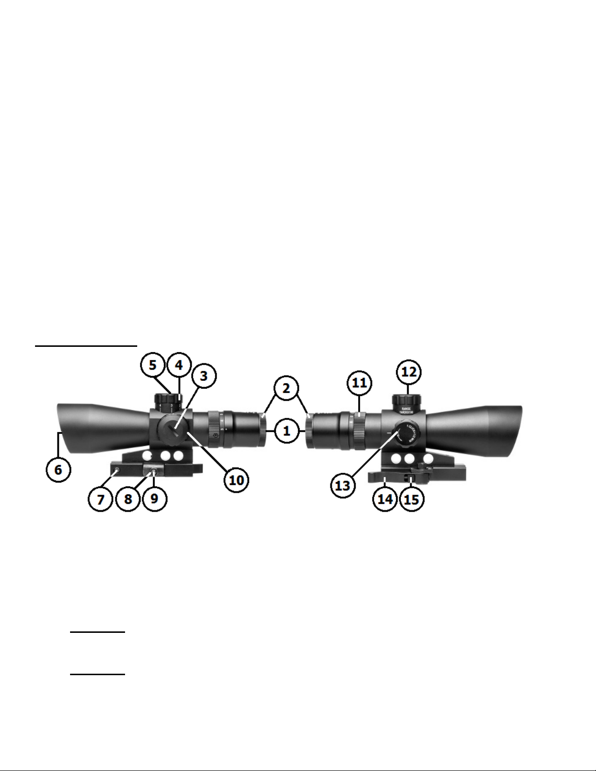
1. OCCULAR LENS
2. QUICK FOCUS EYEPIECE
3. BATTERY CAP
4. BULLET DROP COMPENSATOR TURRET
(BDC calibrated for: M193 5.56 55gr. FMJ)
5. ELEVATION ADJUSTMENT (Inside top of BDC Turret)
6. OBJECTIVE LENS
7. RECOIL LUG (Bottom of mount)
8. LOCKING HEX NUT (For Rail Tension adjustment)
9. SLOTTED SET SCREW (For Rail Tension adjustment)
10. RHEOSTAT KNOB (Illuminated Reticle Blue or Green)
11. MAGNIFICATION RING (3X-9X models only)
12. ELEVATION CAP
13. WINDAGE ADJUSTMENT
14. QUICK RELEASE LEVER
15. AUTO LOCKING LATCH
GENERATION 2
The Mark III Tactical Gen 2 scope series offer several compact tactical optic models that are
packed with many of the popular features that are ideally suited for Tactical Shooters.
With a built in M193 5.56 55gr. FMJ Bullet Drop Compensator feature, a shooter can engage
targets at varying distances much easier. The centerline of the Gen 2 scope is set at the proper 1½”
AR15 height for a more comfortable and natural cheek weld on an AR15 platform. The increased
clearance room under the Gen 2 Ocular housing will make it compatible with more low profile Rear
Flip-Up Iron Sight models. The lower profile Gen 2 BDC turret will allow the lower mounting of the
optional Micro Dot optic & MD mount, when mounted onto the top of the scope providing a
secondary optic system. The improved auto Locking Quick Release mounting system makes for a
secure, quick, easy mounting, and removal of the optics from your firearm.
NcSTAR scopes are also backed by our Lifetime Limited Warranty. We trust that you will receive
many years of enjoyment and service from your new Mark III Tactical Scope.
For optimum performance, please follow all of the procedures in this owner’s manual very
carefully.
KEY FEATURES
CAUTION: BE SURE THAT YOUR FIREARM IS UNLOADED AND POINTED IN A SAFE
DIRECTION. PRACTICE SAFE FIREARM HANDLING PROCEDURES AT ALL TIMES.
CAUTION: CAREFULLY FOLLOW ALL OF THE MOUNTING PROCEDURES. FAILURE
TO DO SO CAN CAUSE DAMAGE TO YOUR SCOPE OR FIREARM
MOUNTING THE OPTIC:
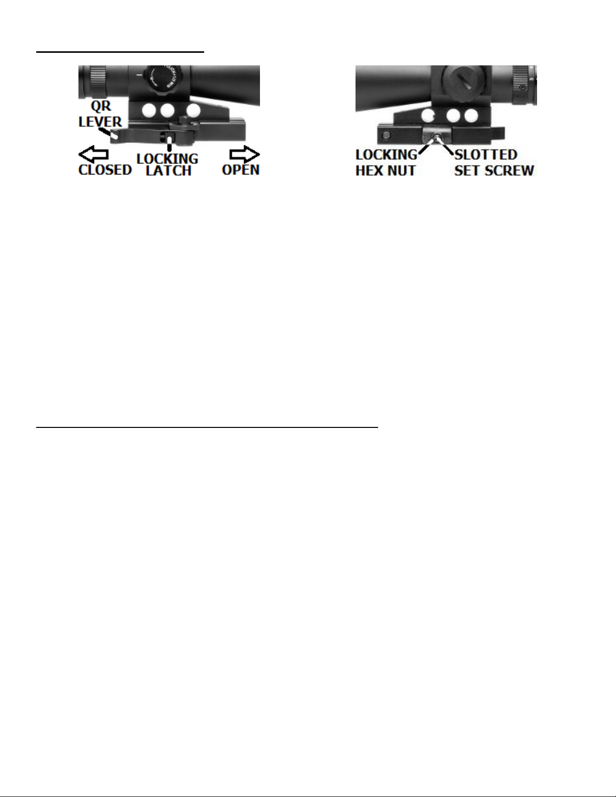
Figure 1
Figure 2
This Optic is equipped with a Quick Release Weaver & Picatinny type rail Mount with an auto
Locking Latch. You should place your firearm on a secure platform, such as a gun vise, before
performing any of the following procedures.
To attach the Optic to a Weaver or Picatinny type rails, move the Locking Latch located within
the Quick Release Lever away from the lever pivot point (to unlock the lever) and then swing the
Quick Release Lever to the forward (Open) position. Place the Optic onto the rail, with the Recoil Lug
placed into one of the cross slots on the rail. Swing the Quick Release Lever rearward (Closed)
position to secure the Optic onto the rail.
Your scope mount is the link between your firearm and your optics. It is very important to
have a solid connection between the two, in order to ensure a consistent zero and proper function of
all the components.
ADJUSTING THE RAIL TENSION OF THE MOUNT:
If the scope’s mount does not fit your firearms rail securely, you can adjust the rail tension of the
mount by following these instructions:
1. To perform this action, move the Quick Release Lever to the Closed position pointing
towards the Ocular Lens/ Eyepiece (Fig. 1). Begin by loosening the Locking Nut on the left
side of the mount. Using a wrench, turn the Locking Hex Nut Counter-Clockwise (Fig. 2).
2. Next, Slide the Locking Latch away from the lever pivot point and swing the Quick Release
Lever to the Open position pointing towards the Objective Lens. Using a flat blade
screwdriver, loosen the Slotted Set Screw in order to fit the mount onto the rail of your
firearm. Seat the scope on top of your firearm’s optics rail with the Objective Lens pointing
towards the muzzle of the firearm. Shoulder the firearm and adjust the position of the scope
on the optics rail until you have achieved the proper eye relief and maximum field of view
through the scope. Once you have your scope positioned properly, close the Quick Release
Lever. Now, tighten the Slotted Set Screw until it is snug using a flat blade screwdriver.
3. At this point your scope and mount are in place, but they are not yet anchored to the
firearm solidly. Open the Quick Release Lever and make small adjustments to the Slotted Set
Screw. Open and Close the Quick Release Lever checking the tightness of the mount.
Perform this action as many times as necessary until the mount is set firmly atop the rail.

4. Once you have properly tightened the Slotted Set Screw and checked the rail tension of the
1. Hold your firearm and look through your scope in a comfortable
position to where you see a full field of view. Make quick glances
through the eyepiece at a featureless, flatly lit area such as a wall
or open sky.
2. Rotating the eyepiece Counter-Clockwise will extend the
eyepiece outward (generally suitable for those who are Far
Sighted). Rotating the eyepiece Clockwise will bring the eyepiece
back into the Ocular Lens housing (generally suitable for those who
are Near Sighted) Fine tune your adjustments until the reticle
appears clear and sharp.
3. Once the eyepiece reaches the outer limits of adjustment, be
sure not to force it so as not to ruin the integrity of the seals.
Figure 3
Figure 4
Your Mark III Tactical Scope is equipped with adjustment
turrets for Windage and Elevation. The Elevation Adjustment
turret is located within the Bullet Drop Compensator (BDC) on top
of the turret housing. To access the Elevation Adjustment, remove
the slotted Elevation Cap on top of the BDC by using a thin coin or
a flat blade screwdriver.
Turning the Elevation Adjustment Counter-Clockwise will move
the crosshairs Up, moving your bullet impacts Down. (Fig. 4).
Turning the Elevation Adjustment Clockwise will move the
crosshairs Down, moving your bullet impacts Up.
Replace the Slotted Elevation Cap once you have made all
necessary adjustments.
mount connection by opening and closing the Quick Release Lever, you can now tighten the
Locking Hex Nut to secure the adjustments you have made. Tighten the Locking Hex Nut with
the Quick release lever in the closed position for best results. Be sure not to over tighten the
Locking Hex Nut to avoid stripping it. You have now successfully mounted your scope and
adjusted the rail tension of the mount. By simply opening the Quick Release lever and pivoting
the scope in the direction of the locking nut, you can easily remove the scope from your firearm.
CAUTION: IT DOES NOT TAKE A LOT OF FORCE TO GET THIS UNIT MOUNTED
SECURELY. BE CERTAIN NOT TO OVER TIGHTEN THE SLOTTED SET SCREW TO
AVOID STRIPPING THE THREADS. DAMAGE CAN ALSO OCCUR TO QUICK
RELEASE LEVER IF TOO MUCH FORCE IS APPLIED.
FOCUSING YOUR SCOPE
Your Mark III Tactical Gen 2 Scope is equipped with a Quick Focus Eyepiece on the rear of the Ocular
Lens, easily distinguished by the serrated ring (Fig. 3). Once your scope is properly mounted you can
focus your reticle to ensure a clear and crisp image.
ZEROING YOUR SCOPE

The Windage Adjustment turret is located on the right
side of the scope body. This Windage Adjustment is an open
Target style turret for ease of access (Fig. 5).
Twisting the Windage Adjustment Counter-Clockwise will
move the crosshairs to the Right, moving your bullet
impacts Left.
Twisting the Windage Adjustment Clockwise will move the
crosshairs to the Left, moving your bullet impacts Right.
Figure 5
Windage/Elevation inches of movement per click
50 yards
100 yards
200 yards
300 yards
400yards
1/4”
1/2”
1”
1 1/2”
2”
NOTE: Each click of adjustment changes the point of impact (where the bullet strikes the target) by
the amount shown on the chart below.
We recommend the use of a bore sighting device to save time and ammunition when zeroing your
scope. This device will help you get on paper much quicker. Follow all of the instructions set by the
manufacturer of your bore sighting device very carefully. Once you have achieved a relative zero by
way of bore sighting, it is still necessary to shoot your firearm to ensure an accurate zero.
CAUTION: ALWAYS BE SURE TO REMOVE THE BORE SIGHTING DEVICE FROM YOUR
FIREARM BEFORE SHOOTING ANY LIVE AMMUNITION. FAILURE TO DO SO CAN
RESULT IN DAMAGE TO YOUR FIREARM OR INJURY TO YOURSELF AND THOSE
AROUND YOU.
With some firearms it may not be possible to use a bore sighting device. In this case it will be
necessary to use a more traditional method of zeroing.
WHEN OPERATING ANY TYPE OF FIREARM ALWAYS USE PROPER EYE AND EAR
PROTECTION. BE SURE TO USE YOUR FIREARM IN AN AREA THAT IS PERMISABLE
UNDER LOCAL, STATE, AND FEDERAL LAW.
1. From a steady rest position (such as a shooting bench) fire three to five round shot
groupings at a 100 yard target.
2. Observe where the bullets have struck the target and adjust the Windage and Elevation as
necessary until your point of aim matches your point of impact. Remember, at 100 yards each
click of adjustment will move the crosshairs of the scope roughly 1/2”.
3. Your firearm and scope are now zeroed for 100 yards. To change the zero distance of
your scope you can adjust the Elevation and Windage turrets as needed according to the
ballistics of the cartridge load you are using
4. Your Mark III Tactical Gen 2 scope is also equipped with a Bullet Drop Compensator (top
turret in picture in Fig. 6). A Bullet Drop Compensator (BDC) is designed to compensate for
the natural gravitational pull on the bullet as soon as it leaves the barrel. If you look closely at
the BDC you will notice that it is marked one through five. Each number is represented in

increments of 100 yards. So whatever distance you are shooting at, simply turn the BDC knob
Figure 6
The reticle can be illuminated in two different colors Blue or
Green with multiple brightness levels for each. If you look
closely at the top of the knob you will notice a series of
numbers. “0” represents the OFF position. If you turn the knob
in either direction the reticle will illuminate in Blue or Green
(depending upon the direction that it is turned). Both colors
have three brightness levels each, “1” being the dimmest and
“3” being the brightest. Adjust the brightness level as needed in
accordance with the surrounding conditions. The illumination
will increase reticle visibility especially during dusk and dawn.
When the illumination is turned OFF the reticle will appear as
normal (Black Reticle). Be sure the Rheostat Knob is set to the
“0” position when not in use to preserve battery life.
Figure 7
1. The Battery compartment is located within the Rheostat
Knob (Fig. 7)
2. On the top of the Rheostat Knob you will notice a thin
cap. To remove this cap grasp it firmly with one hand and
twist it counter-clockwise while holding the rheostat knob
firmly in place with the other hand.
3. Remove the old battery and dispose of it properly.
Replace it with a new 3 volt Lithium Battery type CR2032
only. Place the Battery in the Battery compartment with the
Positive “+” terminal facing out. Twist the Battery cap back
on to the Rheostat Knob and hand tighten. Avoid using tools
(such as pliers) to perform this procedure as this may cause
damage to the unit.
to the closest BDC range in 100 yards increments.
NOTE: Since altitude, temperature, wind, rain, and other climatic conditions affect trajectory, you
may experience some slight deviation in the exact settings of your scope from one shooting
session to the next. Also, different cartridge batches, brands, loads, and bullet weights will result
in different points of impact.
ILLUMINATED RETICLE
Your Mark III Tactical Scope is equipped with an Illuminated Reticle that can be turned On and
Off by simply rotating the Rheostat knob located on the left side of the turret housing (Fig. 6)
BATTERY INSTALLATION
Your Mark III Tactical Scope comes ready to use with a pre-installed battery. If the battery life
expires or your scope no longer illuminates, follow these simple instructions:

IF YOU ARE NOT SURE ABOUT ANY OF THE PROCEDURES IN THIS MANUAL,
Item #
Reticle
Type
Reticle
Colors
Magnification
Objective
Diameter
Field of View
ft@100 yrds
Eye Relief
in.
Exit Pupil
mm
Weight
oz.
Length
in.
Click Value
@100 yards
Lens
Coating
STM432GV2 Mil-Dot
STP432GV2 P4 Sniper
STM3942GV2 Mil-Dot
STP3942GV2 P4 Sniper
14.0 - 4.7
Blue &
Green
4X
32 mm
27.3ft
3.0"
8.0
Blue &
Green
3X - 9X
42 mm
36.8 - 12.0 ft
2.0"
17.3
7.5"
½ MOA
Green
15.1
6.6"
½ MOA
Green
ALWAYS SEEK THE HELP OF A QUALIFIED PROFESSIONAL TO AVOID DAMAGE TO
YOUR SCOPE AND YOUR FIREARM.
CARE AND MAINTENANCE
Your Mark III Tactical Gen 2 scope is fog proof, shock proof, and waterproof. However, you
should never try to take it apart or clean it internally. The exposed optical lens surfaces will perform
their best if they are routinely cleaned with a lens brush and/or the lens cloth provided with your
scope.
For a deep cleaning, you can also use high grade camera lens paper and camera lens cleaning
solutions. Never use any other type of materials or solvents other than those designed specifically
for optical lenses to avoid damaging your scope. Clean the outer portion of the lens cavity first with
cotton swabs, clearing as much debris and dust as possible. Then, gently clean the lenses using a
circular motion starting in the center and ending at the edges. Do not rub the lenses continually;
simply wipe in short circular patterns.
Maintain the exterior surfaces of the scope by removing dirt or sand by using a soft brush or a
soft, dry cloth. You can also use a silicone treated cloth to restore luster and protect the scope
against corrosion. Be careful not to touch any part of the lenses with the silicone cloth.
It is not necessary to lubricate any part of the scope as all of the moving parts, such as the:
rheostat, turrets, and the Quick Focus Eyepiece, are permanently lubricated.
When not in use, always store your scope in a dry place with the lens caps on, to prevent
scratches to the lenses.
SPECIFICATIONS

MARK III TACTICAL SERIES
GENERATION 2
FOR TECHNICAL ASSISTANCE CALL:
1-866-NcSTAR-8
(1-866-627-8278)
WWW.NCSTAR.COM
 Loading...