

TACTICAL 3-RAIL SIGHTING SYSTEM
KEY FEATURES
The 3-RAIL SIGHTING SYSTEM is a new generation of modular tactical sighting systems. The
unique sighting system mount that encompasses a magnified scope, allows the shooter to mount
many different accessories directly to the scope for quick and easy access.
You can mount a secondary sight (red dot/ reflex sight), laser targeting, and a tactical flashlight
directly to the scope. The scope has the rail space on the sighting system mount for a wide variety of
accessories.
Keeps the weight of the accessories closer to the center balance of the firearm, avoiding the front
heavy barrel feel of all the accessories mounted at the front end of the barrel.
Fits virtually any Weaver and Picatinny rails, making it possible to fit onto a wide variety of firearms.
NcSTAR scopes are also backed by our Lifetime Limited Warranty. We trust that you will receive
many years of enjoyment and service from your new 3-Rail Sighting System Scope.
For optimum performance, please follow all of the procedures in this owner’s manual very carefully.
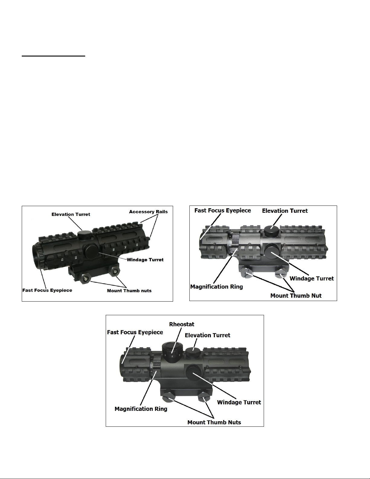
Fig. 1 – Fix Magnification models Fig.2- Variable Magnification models
Fig. 3 - Illuminated Reticle & Variable Magnification models
1

MOUNTING PROCEDURE
Your scope mount is the link between your firearm and your optics. It is very important to have a
solid connection between the two in order to ensure proper function of all the components. You
should place your firearm on a secure platform, such as a gun vise, before performing any of the
following procedures.
CAUTION: CAREFULLY FOLLOW ALL OF THE MOUNTING PROCEDURES. FAILURE
TO DO SO CAN CAUSE DAMAGE TO YOUR SCOPE OR FIREARM
CAUTION: BE SURE THAT YOUR FIREARM IS UNLOADED AND POINTED IN A SAFE
DIRECTION. PRACTICE SAFE FIREARM HANDLING PROCEDURES AT ALL TIMES.
MOUNTING THE SCOPE TO THE WEAVER/PICATINNY RAIL
Follow these mounting instructions:
1. Begin by loosening the Thumb Nuts (counter-clockwise) on the right side of the mount.
2. With the Mount Thumb Nuts loosened, the Mount Rail Clamp should slide out wider from the
base mount. This will allow you to place the scope onto a Weaver or Picatinny rail. You want
to position the scope, so that when you have your firearm shouldered with a proper cheek
weld you have the scope set the proper distance from your eye. Positioning the scope with the
proper eye relief will give you a full field of view through the scope.
3. Once you have the scope properly positioned on your firearm, slide the Mount Rail Clamp
against your firearm’s optics rail. Begin tightening the Thumb Nuts (clockwise) against the Rail
Clamp to secure the scope to the firearm.
4. Check and verify that the scope is firmly secured and properly mounted onto your firearms
optic rail. Check to see if the scope is position correctly on the firearm’s rail, so when it’s
shouldered that the scope is at a comfortable distance from a proper cheek weld and that you
have a full field of view through the scope.
2
LEVELING YOUR RETICLE
With the scope mounted onto your firearm, you may have to adjust the scope in the three rail
mounting system to be plumb and level with the firearm.
If you have to adjust the scope, secure the rifle in a rifle rest, making sure the firearm is plumb and
level in the rifle rest. The use of a torpedo or bubble level can help with leveling the firearm and the
scope’s reticle.
To adjust the scope inside the three rail mount, you will have to loosen all the Allen head bolt screws
securing the upper rail mount from the lower base mount. With all the screws loosened, turn the
scope until the reticle is plumb and level with the firearm. The three rail mount has enough
clearance to allow the scope to be turned in either direction to help with leveling the reticle. When
you have the scope properly leveled you can tighten each screw evenly until the scope is securely
mounted inside the upper and lower three rail mount.
FOCUSING YOUR SCOPE
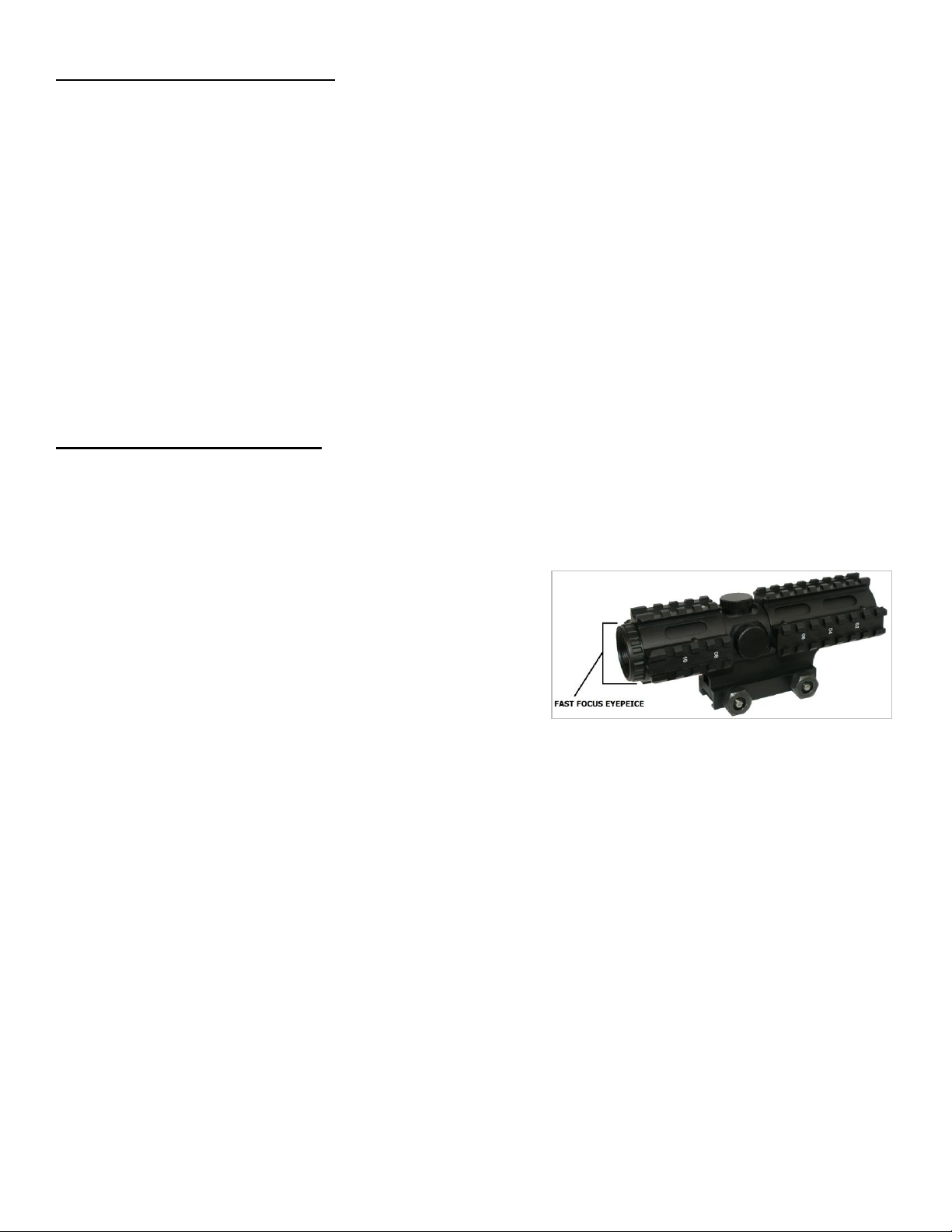
Your 3-Rail Sighting System Scope is equipped with a Fast Focus eyepiece on the rear of the ocular
lens easily distinguished by the serrated ring (Fig. 4). Once your scope is properly mounted you can
focus your reticle to ensure a clear and crisp image.
Figure 4
1. Hold your firearm and look through your scope in a
comfortable position to where you can see a full
field of view through the scope.
2. Make quick glances through the eyepiece at a
featureless, flatly lit area such as a wall or open
sky.
3. Spinning the eyepiece counter-clockwise will extend the eyepiece outward (generally suitable
for those who are far sighted). Spinning the eyepiece clockwise will bring the eyepiece back
into the ocular lens housing (generally suitable for those who are near sighted)
4. Fine tune your adjustments until the reticle appears clear and sharp. Once the eyepiece
reaches the outer limits of adjustment, be sure not to force it so as not to ruin the integrity of
the seals.
3

ZEROING YOUR SCOPE
Windage/Elevation inches of movement per click
50 yards
100 yards
200 yards
300 yards
400yards
¼”
½”
1”
1 ½”
2”
Your 3-Rail Sighting System Scope is equipped with adjustable turrets
for Windage and Elevation. To access the Elevation adjustments
remove the Elevation Cap on top of the scope by twisting it counterclockwise (Fig. 5).
Twisting the Elevation adjuster counter-clockwise move the point of
impact up and twisting the Elevation adjuster clockwise will move the
point of impact down. Replace the Elevation Cap once you have made
all necessary adjustments. Figure 5
The Windage adjuster is located on the right side of the scope. To
access the Windage adjustments remove the Windage Cap on
right side of the scope by twisting it counter-clockwise. (Fig. 6).
Twisting the Windage adjuster counter-clockwise will move the
point of impact to the right, and twisting the Windage adjuster
clockwise will move the point of impact to the left.
Figure 6
NOTE: Each click of adjustment changes the point of impact (where the bullet strikes the target) by
the amount shown on the chart below.
We recommend the use of a bore sighting device to save time and ammunition when zeroing your
scope. These tools will help you get on paper much quicker. Follow all of the instructions set by the
manufacturer of your bore sighting device very carefully. Once you have achieved a relative zero by
way of bore sighting, it is still necessary to shoot your firearm to ensure an accurate zero.
CAUTION: Always be sure to REMOVE the bore sighting device from
your firearm before shooting live ammunition. Failure to do so can
result in damage to your firearm, or injury to yourself and those around
you.
With some firearms it may not be possible to use a bore sighting device. In this case it will be
necessary to use a more traditional method of zeroing.
4

WHEN OPERATING ANY TYPE OF FIREARM ALWAYS USE PROPER EYE
AND EAR PROTECTION. BE SURE TO USE YOUR FIREARM IN AN AREA
THAT IS PERMISABLE UNDER LOCAL, STATE, AND FEDERAL LAW.
1. From a steady rest position (such as a shooting bench) fire three to five rounds at a 100 yard
target.
2. Observe where the bullets have struck the target and adjust windage and elevation as
necessary until your point of aim matches your point of impact. Remember, at 100 yards each
click of adjustment will move the crosshairs of the scope roughly ½”.
3. Your firearm and scope are now zeroed for 100 yards. To change the zero distance of your
scope you can adjust the Elevation and Windage turrets as needed according to the ballistics
of the cartridge load you are using
MAGNIFICATION ADJUSTMENT
For 3-RAIL SIGHTING SYSTEM scope models with a Variable Power Magnification Ring (Fig. 2 &
3), the Magnification Ring is located directly in front of the eyepiece. By turning this ring you can
quickly and easily choose the desired magnification level. Lower levels of magnification provide you
with a wider Field of View, while higher levels of magnification provide you with a closer view of your
target.
BATTERY INSTALLATION
For 3-RAIL SIGHTING SYSTEM Scopes equipped with an Illuminated Reticle (Fig. 3), the scope
will come with a battery pre-installed from the factory. To replace the battery follow these simple
steps:
The Battery Compartment is located within the Rheostat Knob on
top of the Scope Body.
On top of the Rheostat Knob you will notice a thin cap. To
remove this cap grasp it firmly with one hand, and twist it
counter-clockwise while holding the Rheostat Knob firmly in
place with your other hand.
Remove the old battery, and dispose of it properly. Replace it
with a new 3 volt Lithium Battery Type CR2032 only. Twist the
battery cap back on the Rheostat Knob and hand tighten. Avoid
using tools (such as pliers) to perform this procedure as this may
cause damage to the Illumination System.
5

ILLUMINATED RETICLE
For 3-RAIL SIGHTING SYSTEM Scopes equipped with an Illuminated Reticle (Fig. 3), the
Reticle can be illuminated in Blue for use when exterior lighting conditions are less than optimal.
Control of the illumination is achieved by simply rotating the Rheostat Knob in one direction or the
other.
If you look closely at the side of the Rheostat Knob you will notice a Dot on the left side of the
rheostat knob and a series of numbers. The ‘Dot’ will indicate the current position of the rheostat
knob, “0” represents the Off position. If you turn the knob in either direction the reticle will
illuminate blue. The illumination reticle can be set to 7 levels of intensity, “1” being the dimmest and
“7” being the brightest. Adjust the brightness level as needed in accordance with the surrounding
conditions. The illumination will increase reticle visibility, especially during dawn and dusk. This
illuminated scope is not intended for use in total darkness. When the illumination is turned off the
reticle will appear as normal, with Black reticle lines. Be sure that the Rheostat Knob is set to the “0”
position when not in use to preserve battery life.
CARE AND MAINTENANCE
Your 3-Rail Sighting System scope is shock proof and waterproof. However, you should never try to
take it apart or clean it internally. The exposed optical lens surfaces will perform their best if they
are routinely cleaned with a lens brush and the lens cloth provided with your scope. For a deep
cleaning, you can also use high grade camera lens paper and camera lens cleaning solutions. Never
use any other type of materials or solvents other than those designed specifically for optical lenses to
avoid damaging your scope. Clean the outer portion of the lens cavity first with cotton swabs,
clearing as much debris and dust as possible. Then, gently clean the lenses using a circular motion
starting in the center and ending at the edges. Do not rub the lenses continually; simply wipe in
short circular patterns. Maintain the exterior surfaces of the scope by removing dirt or sand by using
a soft brush or a soft, dry cloth. You can also use a silicone treated cloth to restore luster and
protect the scope against corrosion. Be careful not to touch any of the lenses with the silicone cloth.
It is not necessary to lubricate any part of the scope as all of the moving parts, such as the turrets
and the fast focus eyepiece, are permanently lubricated. When not in use, always store your scope
in a dry place with the lens caps on to prevent scratches to the lenses.
If you are not sure about any of the procedures in this manual, always
seek the help of a qualified professional to avoid damage to your scope
and your firearm.
6

SCOPE SPECIFICATIONS
Item # Reticle types
Magnification
Tube
Diameter
Objective
Diameter
Field of View (ft.
@ 100 yrds)
Eye Relief
(in.)
Exit Pupil
Weight
(oz.)
Length
(in.)
Click Value @ 100
yards
Lens Coating
SC3RSM432B Mil-Dot
SC3RSP432B P4 Sniper
SC3RSR432B Range Finder
4X
34mm
32mm
24.9ft
3.1 in.
21.27 oz
6.9 in
½ MOA per click
Blue
7mm
Item # Reticle types
Magnification
Tube
Diameter
Objective
Diameter
Field of View
(ft. @ 100 yrds)
Eye Relief
(in.)
Exit Pupil
Weight
(oz.)
Length
(in.)
Click Value @ 100
yards
Lens Coating
SC3RSM2732G Mil-Dot
SC3RSP2732G P4 Sniper
SC3RSR2732G Rangefinder
SC3RSM3942G Mil-Dot
SC3RSP3942G P4 Sniper
SC3RSR3942G Rangefinder
26.6 oz
7.1 in
½ MOA per click
Green
3X - 9X
44mm
42mm
36.7ft - 12.0ft
2.0 in.
2X - 7X
34mm
32mm
38.3ft - 12.7ft
3.0 in.
16mm - 4.6mm
19.5 oz
6.9 in
½ MOA per click
Green
9.3mm - 3.1mm
Item # Reticle types
Magnification
Tube
Diameter
Objective
Diameter
Field of View
(ft. @ 100 yrds)
Eye Relief
(in.)
Exit Pupil
Weight
(oz.)
Length
(in.)
Click Value @ 100
yards
Lens Coating
SEC3RSM2732G Mil-Dot
SEC3RSP2732G P4 Sniper
SEC3RSR2732G Rangefinder
SEC3RSM3942G Mil-Dot
SEC3RSP3942G P4 Sniper
SEC3RSR3942G Rangefinder
16mm - 4.6mm
19.3 oz
6.9 in
½ MOA per click
Green
2X - 7X
34mm
32mm
38.3ft - 12.7ft
3.0 in.
3X - 9X
44mm
42mm
36.7ft - 12.0ft
2.0 in.
9.3mm - 3.1mm
26.3 oz
7.1 in
½ MOA per click
Green
Fixed Power Magnification Scope Models
Maximum Windage & Elevation: ±70 MOA, Parallax free (at what distance): 100 yards, Mount: Weaver style
Variable Power Magnification Scope Models
Maximum Windage & Elevation: ±70 MOA, Parallax free (at what distance): 100 yards, Mount: Weaver style
Illuminated Reticle & Variable Power Magnification Scope Models
Maximum Windage & Elevation: ±70 MOA, Parallax free (at what distance): 100 yards, Mount: Weaver style
7
 Loading...