

NCSPA Pipe Arches, Corrugated Steel Pipe, Structural Plate Installation Manual

Installation
Manual for
➤ Corrugated Steel Pipe
➤ Pipe Arches
➤ Structural Plate
NATIONAL CORRUGATED STEEL PIPE ASSOCIATION
08 InstallMan00
INSTALLATION MANUAL — NCSPA
The NCSPA Installation Manual is not a copyrighted publication.
If excerpted or copied, credit to the source would be appreciated.
* * *
The information contained in this Installation Manual is the
product of industry experience and practice. The methods used
to install corrugated steel pipe can affect both its effectiveness
and useful life. The situations described in this publication and
the suggested techniques for installation are general suggestions and guidelines intended to alert installers to the need for
careful review of on-site conditions. Each installation will
require its own individual evaluation. The statements or
descriptions provided herein are for general information only.
The National Corrugated Steel Pipe Association assumes no
responsibility for their use.
* * *
N
ATIONAL CORRUGATED STEEL PIPE ASSOCIATION
1255 Twenty-Third Street, NW, Suite 200
Washington, DC 20037-1174
Phone: 202/452-1700 • Fax: 202/833-3636
E-mail: csp@ncspa.org • Web: www.ncspa.org

TABLE OF CONTENTS
FOREWORD .............................................................................................. 3
BASIC PRINCIPLES FOR PROPER
CONSTRUCTION AND INSTALLATION............................................. 4
LOCATION................................................................................................. 5
EXCAVATION............................................................................................. 5
Embankment Condition.................................................................. 5
Trench Condition............................................................................ 5
Trench Width and Shape ................................................................ 6
PREPARING FOUNDATIONS................................................................. 7
Handling Poor Foundations............................................................ 7
Uneven Foundations....................................................................... 8
Soft Foundations............................................................................. 9
Pockets of Unstable Soil ................................................................ 9
Swampy Foundations................................................................... 10
Improved Foundations.................................................................. 10
Settlement Under High Fill Loads............................................... 10
Rock Foundations......................................................................... 11
Arch Foundations......................................................................... 11
ASSEMBLY............................................................................................... 12
Unloading and Handling .............................................................. 12
Connecting Bands ........................................................................ 12
Installing Connecting Bands ........................................................ 12
Typical Connecting Bands ........................................................... 14
Gaskets ......................................................................................... 16
Mastic........................................................................................... 17
Asphalt Coated Pipe..................................................................... 17
Paved-Invert Pipe.......................................................................... 17
Full Lined Pipe............................................................................. 18
Polymer Coated Pipe .................................................................... 18
Pipe Arch...................................................................................... 18
Field Coated Structural Plate Structures...................................... 18
Structural Plate Structures ............................................................ 18
Tools Required ............................................................................. 19
Erection ........................................................................................ 19
Long Span Structures................................................................... 21
Lifting Assistance......................................................................... 21
End Treatment.............................................................................. 21
Cut End......................................................................................... 22
CSP Installation Manual 1
08 InstallMan00

ASSEMBLY (continued)
Cut-Off Walls ............................................................................... 23
End Sections................................................................................. 24
Other End Finishes....................................................................... 24
Stream Diversion .......................................................................... 24
BACKFILLING ........................................................................................ 25
Backfill Material........................................................................... 25
Placing the Backfill...................................................................... 25
Pipe Arches................................................................................... 30
Arches........................................................................................... 30
Large Diameter Structures ........................................................... 32
Proper Material Placement........................................................... 32
Even Placement of Backfill.......................................................... 33
Shape Control............................................................................... 33
Multiple Installations.................................................................... 34
Long Span Structures................................................................... 35
Final Backfilling........................................................................... 35
COMPACTION EQUIPMENT............................................................... 35
Hand Compaction......................................................................... 35
Mechanical Compactors............................................................... 36
Roller Compactors........................................................................ 36
Vibrating Compactors .................................................................. 36
Hydraulic Compaction ................................................................. 36
Structure Protection ...................................................................... 36
Construction Loads ...................................................................... 37
Hydraulic Protection .................................................................... 38
SUMMARY............................................................................................... 40
SUBDRAINAGE ....................................................................................... 41
Underdrain Pipe............................................................................ 41
Flow Line ..................................................................................... 41
Preparing the Foundation ............................................................ 41
Assembly of Underdrain Pipe...................................................... 41
Proper Placement of Underdrain Pipe.......................................... 42
APPENDIX................................................................................................ 44
Culvert Grades and Outfall Treatment ......................................... 44
Length of Culverts........................................................................ 44
Skew Number............................................................................... 47
National Corrugated Steel Pipe Association 2

FOREWORD
This manual is intended for both the contractor and the engineer. It provides
practical information for the installation of corrugated steel pipe as storm
sewers or culverts. It also provides the necessary considerations for proper
design to achieve long term performance of the culvert or storm sewer.
Corrugated steel pipe with its high load carrying capacity, strong joints and
exceptional beam strength is installed more easily than other types of conduit. However, the correct installation procedures must be followed to insure
full investment value in the structure.
It is the intent of this manual to suggest ways and means of improving
installation practices. It is not intended to be used as a direct specification, but rather as a practical field guide for the installation of corrugated steel pipe, pipe arch and structural plate.
Too much emphasis cannot be placed on the necessity of adequate
compaction of backfill. Faulty compaction has led to more trouble with
pipe installations, flexible and rigid, than all other factors combined!
OSHA safety regulations and guidelines must be observed during all phases
of construction including foundation preparation, excavation, pipe handling,
assembly and backfilling.
Additional information is available in the AISI Handbook of Steel Drainage
and Highway Construction Products and ASTM Specifications A 798 and
A 807.
This manual uses dual units of measure with Imperial units shown first followed by metric units in parentheses. Complex drawings or tables may be
duplicated in metric.
CSP Installation Manual 3

BASIC PRINCIPLES FOR PROPER
CONSTRUCTION & INSTALLATION
Project plans and specifications provide the basic requirements for construction and installation. However, site conditions often vary from those anticipated during design. The contractor and construction engineer must recognize these variations. Often, alternate or additional construction considerations are necessary. The following guidelines provide specific considerations
and details for various conditions in a step-by-step construction sequence.
The following summary will appear again near the end of the manual.
However review it now as a basic outline of the steps required for a proper
installation:
1) Check alignment in relation to the plans as well as the
actual site conditions.
2) Make certain the pipe length(s), necessary appurtenances,
etc. are correct.
3) Excavate to the correct width, line and grade.
4) Provide a uniform, stable foundation—correct site conditions as necessary.
5) Unload, handle and store the pipe correctly.
6) Assemble the pipe properly—check alignment, follo w special procedures for the connecting bands, gaskets, and
other hardware used. (For structural plate structures,
achieve properly aligned plate laps, bolt torque, and
assembled dimensions.)
7) Use a suitable (granular) backfill material as required in
the plans and specifications.
8) Maintain proper backfill width.
9) Haunch the pipe properly.
10) Place and compact the backfill in 6 to 8 inches (150 to 200
millimeters) of thickness of compacted lifts.
11) Install the necessary end treatment quickly to protect the
pipe and your efforts.
12) Protect the structure from heavy construction equipment
loads, other heavy loads and hydraulic forces.
4 National Corrugated Steel Pipe Association

LOCATION
Before installing any drainage structure, it is best to first recheck the planned
alignment and grade (position and percent of slope) of the pipe in relation to
the topography of the site. Even when complete construction plans are supplied, a careful examination of the site should be made.
EXCAVATION
Embankment Condition
The only excavation typically required for an embankment condition is to
remove the topsoil, muck and organic matter and prepare a stable foundation
at the proper elevation and grade.
Trench Condition
Most storm sewers are installed in trenches. Although pipes can be easily
installed in a trench, there are some general guidelines that should be followed.
All trench excavation should proceed only after OSHA and other safety
requirements are met. Trench excavation normally proceeds in the upgrade
direction. Most trenching equipment is more efficiently operated in this manner, and pipe sections are also more easily joined when progressing in this
direction. If excavated spoil is to be used as backfill, it should be stockpiled
at a safe distance from the edge of the trench. As a general rule, when trench
walls are unsupported, the distance from the trench edge to the toe of the
stockpiled material should not be less than one-half the depth of the trench.
When trench walls are protected by some form of sheeting or shoring, a safe
minimum distance between the trench edge and stockpiled material must still
be maintained, but will vary with soil and bracing types.
Care should always be exercised in the operation of equipment in the vicinity of an open trench. Operated too close to the trench, equipment weight and
vibration may collapse the trench walls. The three phases of construction in
a trench (excavation, pipe installation, and backfilling) should be scheduled
in close sequence with each other. An open trench is dangerous and vulnerable to accidents. An open excavation can result in damage to the project
under construction. The two main hazards that must always be considered in
trenching work are:
➤ Stability of trench walls; and
➤ W ater that may accumulate in the trench resulting from seepage and
surface runoff.
CSP Installation Manual 5

T o minimize accidents and losses resulting from trenching operations the following procedures should be followed:
➤ Begin excavation only when installation of pipe can immediately
follow.
➤ Protect trench walls to insure their stability throughout the con-
struction period.
➤ Follow procedures that will keep the trench free of seepage and sur-
face waters.
➤ Excavate the trench at the same rate as pipe installation with a min-
imum distance, as dictated by safety, separating the two operations.
➤ Backfill the trench as soon as practicable after pipe installation.
Trench Width and Shape
The width and shape of the trench should be as shown on the plans. Any
change should be approved by the Engineer.
Generally, the trench width will be specified as 12 to 48 inches (300 to 1200
millimeters) wider than the pipe. However, it must be wide enough to allow
the critical lower quadrants of the pipe to be properly backfilled (haunched).
Figure 16 provides guidelines about minimum spacing between multiple
structures. These same guidelines can be used to provide the necessary width
between the pipe and trench wall to adequately place typical backfill. Lesser
spacing may be used with slurries and other backfill materials that do not
require mechanical compaction.
6 National Corrugated Steel Pipe Association

PREPARING FOUNDATIONS
Foundation requirements should be detailed on the plan sheets. However,
field conditions often vary requiring special attention and alterations that are
discovered only during excavation. Any alterations should first be approved
by the Engineer.
Although corrugated steel drainage structures can experience some uneven
settlement without disjointing or breaking, they should be placed on a firm,
uniform foundation for best performance and long service life.
All storm sewers and culverts must be installed with the area under the
haunches well compacted and all voids filled.
For corrugated steel pipe, the most popular method of preparing the foundation is by excavating to a flat surf ace and then carefully tamping the fill under
the haunches of the pipe. Proper backfill density can be achieved by compacting the soil with a wooden pole, 2 x 4, or the smaller sizes of pneumatic
tampers to eliminate all voids under the structure. See Figure 1 for typical
methods of bedding corrugated steel structures and the 2 x 4 description.
This “flat foundation” technique works well except for larger pipe-arches
and horizontal ellipses. The vee-shaped bedding technique for these structures is shown in Figure 12.
All pipe must be placed on stable earth or fine granular foundation. Never
install them on sod, frozen earth or on a bed that contains large boulders or
rock. When poor foundations with low bearing strength are encountered,
investigate the possibility of a change in pipe location. Otherwise, it may be
necessary to stabilize the poor foundation by a method described in the next
section.
Care must be taken to prevent water leaking through the fill or along the
pipe. When granular materials have been added for bedding, the ends of the
fill should be sealed against infiltration. This can be done by bedding the
ends in well compacted clay or by adding some type of end treatment such
as an end section or a cut off wall.
Handling Poor Foundations
If poor or non-uniform foundations are encountered, they must be treated
correctly to assure satisfactory results. The critical factor is to achieve uniformity along the pipe with a tendency for the foundation to yield under the
pipe in relation to alongside the pipe.
CSP Installation Manual 7

Uneven Foundations
When the excavated grade line reveals both soft and hard spots, the foundation must be changed to make it as uniform as possible. Sometimes hard
spots can be excavated below grade and replaced with softer material.
Alternatively, it may be more economical to excavate the entire foundation
slightly below grade line and replace it with suitable, uniform material. In
any event, any abrupt changes from hard to soft foundation must be avoided.
8 National Corrugated Steel Pipe Association
Figure 1. Methods for attaining proper compaction under haunches of CSP
and pipe-arch.
*Note: When tamping with a 2 x 4, the designation of 2 x 4 will remain in
usage as a descriptive expression without conversion to metric. It
represents an approximate lumber cross-section of 40 by 90 millimeters.
Soft Foundations
When soft, unstable material is encountered at the foundation level, it must
be excavated below the flow line grade and backfilled to grade with sand,
gravel, crushed stone or other suitable material. The zone of select material
must be adequate to support the pipe and backfill. When unexpected materials are encountered, consult the Engineer.
Pockets of Unstable Soil
If unstable foundation material is in small pockets, it is best to excavate all
of the poor foundation and replace it with suitable backfill material.
Frequently, a relatively thin mat of granular material will provide satisfactory support, but it may be necessary to replace v ery soft foundations to a depth
great enough to support not only the pipe, but also the hea vier backf ill placed
beside it.
CSP Installation Manual 9
Figure 2.
Direction of desired relative movement shown by arrows.
Treatment for Soft Foundations
Swampy Foundations
Corrugated steel pipe must not be placed in direct contact with pipe bents or
concrete cradles that are installed to help provide a foundation. Such supports, if used, should be built with a flat top and covered with an earth cushion. In this way the flexible structure can develop side support without concentrating the load at any point.
Improved Foundations
(soft, uneven, unstable or swampy)
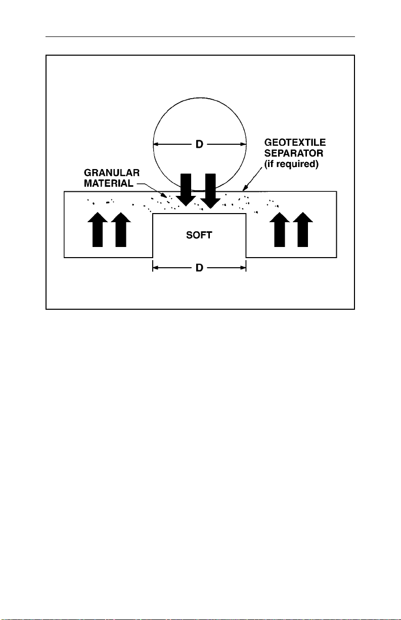
Whenever a foundation is stabilized by using a coarse granular material, consideration of the bedding and backfill material becomes even more important. Fine materials can migrate into coarser materials and geotextile separators are often required to prevent this migration.
Settlement Under High Fill Loads
(camber for embankment installations)
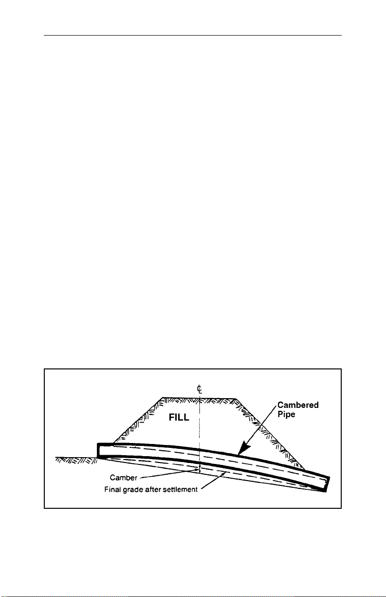
Cambering the center part of the foundation will compensate for unequal settlement under the weight of heavy embankments. This assures proper grade
after settlement and prevents the structure from sagging in the middle as the
foundation consolidates. Generally, sufficient camber can be obtained by
installing the upstream half of the pipe on a flat grade and the downstream
half on steeper than normal grade as shown in Figure 3. If camber is considered necessary based on foundation soil conditions, the amount of camber
10 National Corrugated Steel Pipe Association
Figure 3. Correct method of cambering pipe to compensate for unequal settle-
ment under high fills. Should be in accordance with procedure given
in the AISI Handbook of Steel Drainage and Highway Construction
Products.
must be determined by a qualified soils engineer. If the pipe is setting on
cushioned rock or other adequate strength foundation, no camber is necessary, as settlement will be minor.
Be careful not to raise the center of the pipe above the inlet, as this will pocket water in the pipe.
Rock Foundations
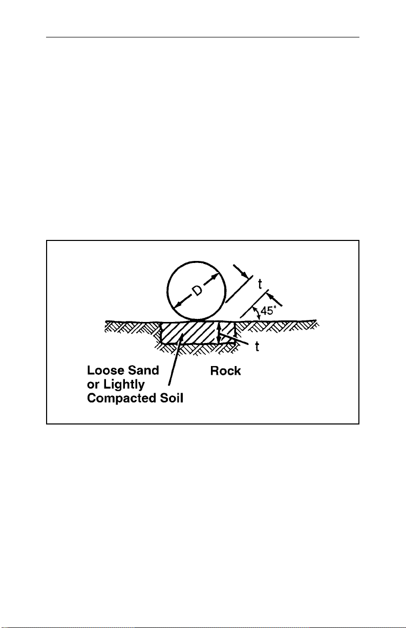
Rock encountered in the foundation must be removed to provide more than
the minimum bedding thickness underneath the bottom of the structure.
Excavate wide enough to av oid any possibility of the pipe resting on rock and
provide access to adequately haunch the pipe as shown in Figure 4. The e xcavated area is then backfilled with compacted,granular soil to cushion the pipe.
Arch Foundations
Arches differ from other structural plate structures in that they are generally
erected on concrete foundations. The key way or unbalanced channel in
which the arch rests must be accurately built to the proper line, grade and
spacing for easy assembly of the plates. The unbalanced channels must be
carefully located to insure that the holes correctly align with those in the
plates to permit bolting. They must be properly oriented (angled) to receive
the plate.
CSP Installation Manual 11
Figure 4. Method of handling rock foundations. t = 1/2 inch (13 millimeters) per
foot (.30 meter) of fill over pipe,with 24 inches (.60 meter) the maximum.

ASSEMBLY
Unloading and handling
Pipe must never be dumped directly from a truck bed while unloading.
Although corrugated steel drainage structures withstand normal handling
they should be handled with reasonable care. Dragging the pipe at any time
may damage the coatings. Also avoid striking rocks or hard objects when
lowering pipe into trenches.
Since corrugated steel pipes are relatively light weight, they can be handled
with light equipment. Use of slings is recommended to properly handle the
pipe.
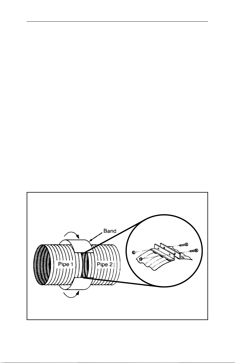
Connecting Bands
The usual method of joining two or more lengths of pipe or pipe arch is by
steel connecting bands. The bands engage the ends of each pipe section. They
are placed to overlap each pipe section equally. The corrugations on the band
must fit into the corrugations of each pipe. Tightening of bolts draws the
band tightly around the adjacent ends of pipe lengths, providing an integral
and continuous structure.
One piece bands are used for most installations of smaller sizes of pipe.
“Two-piece” bands are used on larger diameter pipe and when installation
conditions are difficult. “Rods and Lugs” are used on levees, aerial sewers
and similar installations where bands that provide tighter and stronger joints
are essential.
Typical bands, and their method of installation, are illustrated in Figures 4A
to 4E. Specially fabricated bolted, welded or riveted connectors can be supplied for use in jacking and for special or unusual conditions. If the pipe ends
have been match marked by the fabricator, then they must be installed in the
proper sequence.
Installing Connecting Bands
During the construction of a corrugated steel pipe system, care must be giv en
to the assembly of joints to control both infiltration and exfiltration. Both
processes will have an effect upon backfill materials since soil particle
migration can occur. This is particularly true when fine “rained soils (fine
sands and silts) are present in the backfill material. When necessary, a gasket, a geotextile wrap,or both can also be used to control infiltration of fines.
12 National Corrugated Steel Pipe Association
Bands are put into position at the end of one section of pipe with the band
open to receive the next section. The next section is brought against or to
within 1 inch (25 millimeters) of the first section. After checking to see that
connecting parts of both band and pipe sections match, that the interior of
bands and exterior of pipe are free of dirt, stones, etc., bolts are inserted and
tightened.
To speed the coupling operation, especially for large diameter structures, a
cinching device will help draw the band up tight. Special coupling devices
can be used to fit over the connecting bands and quickly draw them together. Advantage of these devices is that they permit faster hand-tightening of
the bolts, so that a wrench is needed only for final tightening.
On large diameter pipe and asphalt coated pipe, merely tightening bolts will
not assure a tight joint, due to the friction between the band and the pipe
ends. In such installation, tap the band with a mallet to take up the slack as
the band is tightened.
The wrench used to tighten coupling bands may be a deep socket or ratchet
wrench for greater speed.
CSP Installation Manual 13
Figure 4A. Typical connecting band is wrapped around the joint and drawn
together.
Band Angle Connector
14 National Corrugated Steel Pipe Association
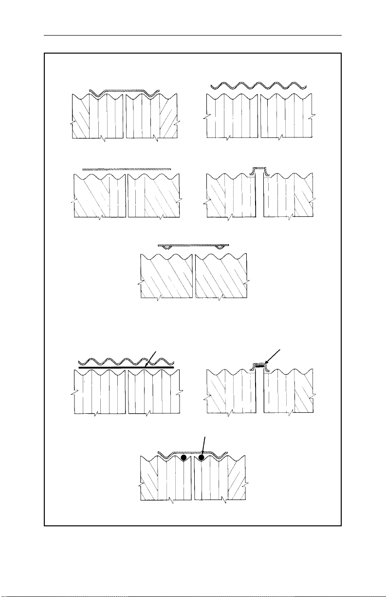
Figure 4B. Standard and Gasketed couplers for corrugated steel pipe.
Standard Couplers
Gasketed Couplers
Semi-Corrugated (Hugger) Corrugated (Annular)
Corrugated (Annular)
Sleeve Gasket Mastic or Gasket
O-Ring
Semi-Corrugated (Hugger)
Hat
Flat Hat
Universal*
*Unless a dimple fills
each corrugation
valley, a suitable
gasket or geotextile
wrap is required
 Loading...