

Page 1
User Guide
NCR XL10W (5910)
Release 1.0 and 1.1
BCC5–0000–5197
Issue C
Page 2

The product described in this document is a licensed product of NCR Corporation.
NCR is a registered trademark of NCR Corporation. NCR RealPOS is a trademark of NCR Corporation in
the United States and/or other countries. Other product names mentioned in this publication may be
trademarks or registered trademarks of their respective companies and are hereby acknowledged.
The terms HDMI and HDMI High-Definition Multimedia Interface, and the HDMI Logo are trademarks
or registered trademarks of HDMI Licensing LLC in the United States and other countries.
Where creation of derivative works, modifications or copies of this NCR copyrighted documentation is
permitted under the terms and conditions of an agreement you have with NCR, NCR's copyright notice
must be included.
It is the policy of NCR Corporation (NCR) to improve products as new technology, components,
software, and firmware become available. NCR, therefore, reserves the right to change specifications
without prior notice.
All features, functions, and operations described herein may not be marketed by NCR in all parts of the
world. In some instances, photographs are of equipment prototypes. Therefore, before using this
document, consult with your NCR representative or NCR office for information that is applicable and
current.
To maintain the quality of our publications, we need your comments on the accuracy, clarity,
organization, and value of this book. Please use the link below to send your comments.
EMail: FD230036@ncr.com
Copyright © 2017–2018
By NCR Corporation
Atlanta, GA U.S.A.
All Rights Reserved
Page 3

Preface
Audience
This book is written for hardware installer/service personnel, system integrators, and
field engineers.
Notice: This document is NCR proprietary information and is not to be disclosed or
reproduced without consent.
Safety Requirements
The NCR XL10W (5910) conforms to all applicable legal requirements. To view the
compliance statements see the NCR RealPOS Peripherals Safety and Regulatory Statements
(B005-0000-1701).
IT Power System
This product is suitable for connection to an IT power system with a phase-to-phase
voltage not exceeding 240 V.
i
Peripheral Usage
This terminal should only be used with peripheral devices that are certified by the
appropriate safety agency for the country of installation (UL, CSA, TUV, VDE) or those
which are recommended by NCR Corporation.
Warning: DO NOT connect or disconnect any serial peripherals while the terminal
is connected to AC power. This can result in system damage.
Grounding Instructions
In the event of a malfunction or breakdown, grounding provides a path of least
resistance for electric current to reduce the risk of electric shock. This product is
equipped with an electric cord having an equipment-grounding conductor and a
grounding plug. The plug must be plugged into a matching outlet that is properly
installed and grounded in accordance with all local codes and ordinances. Do not
modify the plug provided – if it will not fit the outlet, have the proper outlet installed by
a qualified electrician. Improper connection of the equipment-grounding conductor can
result in a risk of electric shock.
The conductor with insulation having an outer surface that is green with or without
yellow stripes is the equipment-grounding conductor.
If repair or replacement of the electric cord or plug is necessary, do not connect the
equipment-grounding conductor to a live terminal. Check with a qualified electrician or
service personnel if the grounding instructions are not completely understood, or if you
are in doubt as to whether the product is properly grounded.
Page 4

ii
Use only 3-wire extension cords that have 3-prong grounding plugs and 3-pole
receptacles that accept the product’s plug. Repair or replace damaged or worn cords
immediately.
Out of Box Failure (OBF)
If you experience an out of box failure (OBF) during installation or staging related to a
missing, wrong or defective unit or item, simply provide NCR with a detailed
description of the issue and the item will be replaced free of charge. For assistance with
this process send an email to CustomerSat.Retail@ncr.com with the following details:
• NCR Sales Order # (Sales Order # are located on the box)
• Date of Product Installation
• Product Model #
• Unit Serial #
• NCR part # of defective/missing/wrong component
Warranty
• Description of Failure (please be specific. For example: “display will not power on”)
• Customer/Requestor’s contact name, phone number and/or e-mail address
• Address to ship replacement part(s)
Transport the product in its original packaging to prevent impact damages.
If you do not have access to a computer, you may leave a voice message at: 1-800-5288658 (USA), or (International) +1-770-623-7400. When leaving a message, please provide a
phone number and/or an email address so NCR can contact you if additional details are
needed.
Note: Used equipment that experiences a failure does not qualify as an OBF and should
go through the NCR warranty process.
Warranty terms vary by region and country.
All parts of this product that are subject to normal wear and tear are not included in the
warranty. In general, damages due to the following are not covered by the warranty.
• Improper or insufficient maintenance
• Improper use or unauthorized modifications of the product.
• Inadequate location or surroundings. Site installation must conform to guidelines
listed in the Site Preparation section of this document and the NCR Workstation and
Peripheral AC Wiring Guide (BST0-2115-53).
For detailed warranty arrangements please consult your contract documents.
Page 5

Returning Defective Hardware for Service
Use the following procedure to report/return defective hardware.
Call the NCR Customer Care Center at 1-800-262-7782 and have the following information
available when you place the call.
• Class/Model number of the defective equipment
• Serial Number of the defective equipment
• Equipment location in the store
• Description of the problem, including any system error codes, error condition, or
guidance to the area of failure.
The NCR Agent will provide you with a work order number, which serves as your
Return Material Authorization (RMA). Please provide the RMA on the outside of the
shipping box.
Note: A work order must be opened for each device that is shipped for repair.
iii
Page 6

Table of Contents
Chapter 1: Product Overview
Base Models 2
Features and Benefits 3
Display Port Model Optional Features 4
USB-CModel Optional Features 7
Specifications 8
Display Mounts 10
XL10W Wedge Stand (5910-F030/K030) 10
iv
XL–Series Stand (5910-F033, 5910-F233) 10
Integration Tray Mount (5968–K024) 11
X–Series Table Top Stand (5968–K031) 11
Checkstand Mount (5968–K039) 12
WallMount (7702–K320) 12
Third Party Mount 13
VESAFiller Plate (5915–K320) 13
Magnetic Stripe Reader (5910-F141, 5910-F241) 14
Data Encryption 14
Card Data Encoding 14
Card Thickness 14
Miscellaneous Kits 15
5910–F302/K302 15
5915–K470 15
7613–K470 15
7702–K470 16
LabelLocations 17
Display Port Model 17
USB-CModel 18
Page 7

v
Chapter 2: Hardware Installation
Installation Restrictions 19
Ergonomic Workplace 20
Installing the Display 21
Installing the Display to the XL-Series Stand 22
Installing the Display to the XL10W Wedge Stand 29
Installing the Display to the XL10W Pole Mount 32
Connecting to a POS Terminal 36
Display Port Model 36
USB-CModel 42
Chapter 3: Operation and Cleaning
Projected Capacitive Touchscreen 43
Using the PCap Touchscreen 43
Touchscreen Cleaning Procedures 43
Magnetic Stripe Reader 44
Using the MSR 44
Care of Cards 44
Card Thickness 44
Cabinet Cleaning Procedures 45
Chapter 4: NCR Software OSD Utility
Introduction 46
Supported Features 46
Installing the Utility 47
Running the Utility (GUI Version) 48
Main Menu 48
Monitors Detected Panel 48
Center Panel 48
Control Buttons 49
Display Adjustment Procedures 51
Resetting Factory Defaults 52
Running the Utility (Console Version) 53
Page 8

Revision Record
Issue Date Remarks
vi
A
B
C
Nov 2017 First Issue
July 2018 Changed 1432-C681-0013 / 497-0517916 to 1432-C805-0013 / 497-
0521105
Added XL10W Wedge Stand (F030)
Oct 2018 Added Anti-Glare and white features
Added XL10WPole Mount (F302)
Added "Installing the Display to the XL10W Pole Mount" section
Renamed "blank plate" to "filler plate" and "VESA Adapter" to
"VESAFiller Plate"
Page 9
Chapter 1: Product Overview
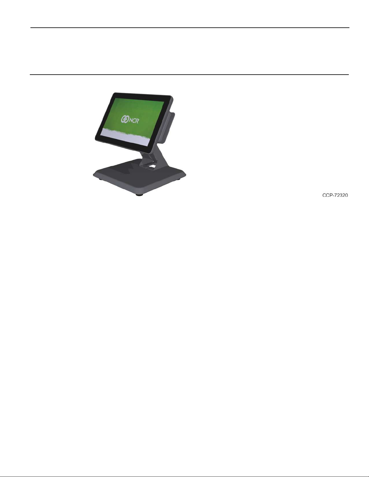
The NCR XL10W (5910) display offers flexibility and ultra–thin design that will look
great in any retail environment. The XL10W display features bright, high contrast LCD
to make it easy to read. This stylish display is available as a 10–inch projected capacitive
(PCAP) touchscreen or LED backlight non–touch.
The XL10W Display Port model is compatible with any product that has a display port
video and a USB interface and the XL10W USB-C model is compatible with any NCR
USB-Cequipped terminal. The XL10W display can be used as an associate display or
rear mounted to a terminal or free standing to display pricing and promotional
messages. This is available with an encrypted magnetic stripe reader (MSR) for
enhanced security. Whichever option is preferred, these displays are sure to enhance
the appearance of the wrap stand or checkout and save valuable counter space.
Page 10
1-2 Product Overview
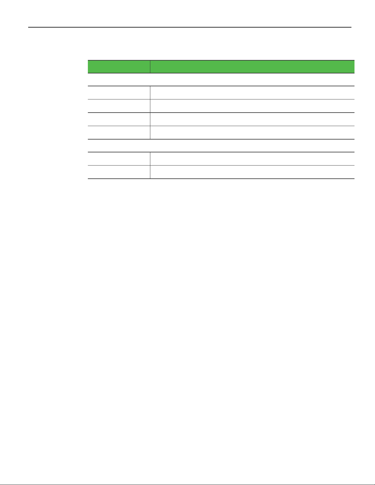
Base Models
Base Model Description
Display Port Model
5910-1010-9090 XL10W, 10.1" Display, No Touch
5910-1310-9090 XL10W, 10.1" Display, PCAP
5910-2310-9090 XL10W, 10.1" Display, PCAP, White
5910-3010-9090 XL10W, 10.1" Display, No Touch with Anti-Glare
USB-C Model
5910-5010-9090 XL10W, 10.1" Display, No Touch, USB-C
5910-5310-9090 XL10W, 10.1" Display, PCAP, USB-C
Page 11

Product Overview 1-3
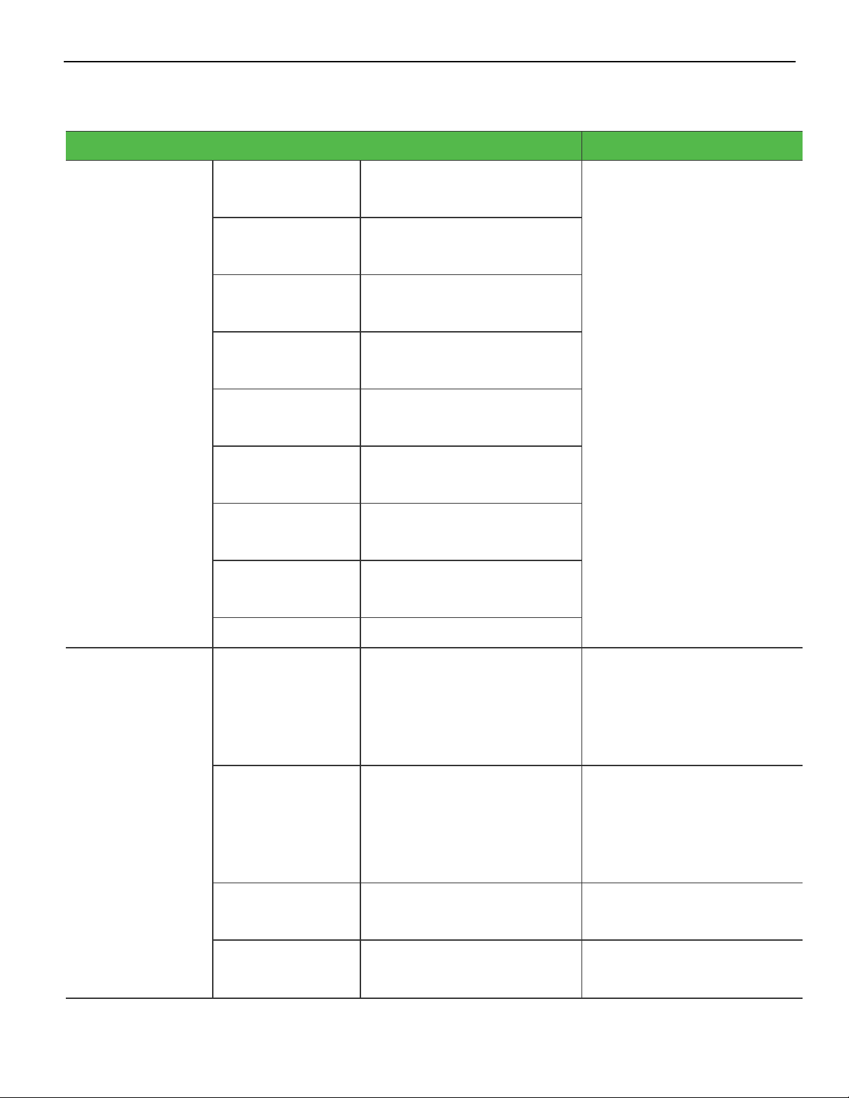
Features and Benefits
Features Description
Touch Displays
Non–Touch Displays
Peripherals
10.1"Projected Capacitive (PCap) • Zero Bezel
• 10–Point Multi–Touch Interface
• 400 NIT LED LCD
• 16:10 Aspect Ratio
• 1920x1200 Resolution
• Display Port or USB-C DPAlt Mode
• Software OSD Support
10.1"LEDBacklight • Zero Bezel
• 400 NIT LED LCD
• 16:10 Aspect Ratio
• 1920x1200 Resolution
• Display Port or USB-C DPAlt Mode
• Software OSD Support
MSR, NCREncrypted USB 3-Track Provides a 3-Track, Encrypting MSR
Filler Plate, Right Side Provides a filler plate when an MSR is not
installed
Filler Plate, Left Side Provides a blank plate when a Port B(Left
Side) feature is not installed
Page 12
1-4 Product Overview
Display Port Model Optional Features
Optional Features Description
Power Cord 5910–F100
1416–C325–0030
5910–F101
1416–C323–0030
5910–F102
1416–C321–0030
5910–F103
1416–C322–0030
5910–F104
1416–C391–0030
5910–F105
1416–C320–0030
5910–F106
1432–C366–0030
5910–F107
USPower Cord Provides a 3 m (118.11 in.)
power cord for an external
power supply.
International Power Cord
UK Power Cord
Australia Power Cord
China Power Cord
SEVPower Cord
IndiaPower Cord
ArgentinaPower Cord
1416–C009–0018
1424–C124–0030
Display Port Cables 1432–C614–0005
5910–F110
1432–C614–0008
5910–F111
1432–C614–0013
5910–F112
1432–C614–0040
Japan Power Cord
0.5 m (19.69 in.) Display Port
Cable
0.84 m (33.07 in.) Display Port
Cable
1.3 m (51.18 in.) Display Port
Cable
4 m (157.48 in.) Display Port
Cable
Provides a display port cable
used for integration with XR7
terminal. To be used only on
displays attached directly to
the XR POStable top stand.
Provides a display port cable
used for integration with XR7
terminal using the rear
display arm of the POS table
top stand.
Provides a display port cable.
Provides a display port cable.
Page 13

Product Overview 1-5
Optional Features Description
ExternalPower
Cables
5910–F120
5915–K100
5910–F121
1432–C591–0013
5910–F122
1432–C591–0040
Universal Switching
MEPSPower Supply - 12V, 2.5
A output (ROHS)
1.3 m (51.18 in.) USBType A
with power connector
4 m (157.48 in.) USBType A
with power connector
Provides a 12VDC Power
Adapter, 40W, DOEVI, 4 pin
Mini-DIN connector.
Provides a USBcable with
latching 1x8 connector on the
display end, a USB connector
on the terminal end, and a
barrel connector in the
middle for an external power
supply. Requires both an
external power brick and a
local power cord.
Provides a USBcable with
latching 1x8 connector on the
display end, a USB connector
on the terminal end, and a
barrel connector in the
middle for an external power
supply. Requires both an
external power brick and a
local power cord.
Page 14

1-6 Product Overview
Optional Features Description
Powered USB
Cables
1432–C477–0005
5910–F117
1432–C477–0008
0.5 m (19.69 in.) 12V Powered
USB
0.84 m (33.07 in.) 12V
Powered USB
Provides a 12V USBpower
cable with latching 1x8
connector on the display end
and a latching 12V USB +
Power connector on the
terminal end. Provides both
power and touch
communication. To be used
only on displays attached to
the XR POS table top stand.
Provides a 12V USBpower
cable with latching 1x8
connector on the display end
and a latching 12V USB +
Power connector on the
terminal end. Provides both
power and touch
communication.
5910–F118
1432–C477–0013
5910–F119
1432–C478–0040
1.3 m (51.18 in.) 12V Powered
USB
4 m (157.48 in.) 12V Powered
USB
Provides a 12V USBpower
cable with latching 1x8
connector on the display end
and a latching 12V USB +
Power connector on the
terminal end. Provides both
power and touch
communication.
Provides a 12V USBpower
cable with latching 1x8
connector on the display end
and a latching 12V USB +
Power connector on the
terminal end. Provides both
power and touch
communication.
Page 15

Product Overview 1-7
Optional Features Description
Audio Cable 5910–F126
1432–C593–0013
5910–F127
1432–C593–0040
Miscellaneous
Adapters
1432–C790–0001
1432–C791–0000
1.3 m (51.18 in.) with 3.5 mm
plug Male
4 m (157.48 in.) with 3.5 mm
plug Male
Cable, HDMI (Terminal) to
Display Port (Display) active
adapter
Adapter, passive, DVI-D to
HDMI
Provides a black cable for use
on terminals with a line–out
or audio port.
Provides a black cable for use
on terminals with a line–out
or audio port.
Allows connection of a
display with DisplayPort to a
terminal with an HDMI
connection. Must also order
the DisplayPort cable.
Powered by a USB port on
terminal.
Allows connection of a
display with DisplayPort to a
terminal with a DVI
connection. Must also order
the DisplayPort cable and the
1432-C790-0001 adapter.
USB-CModel Optional Features
Optional Features Description
USB-CCable 5910–F132
1432–C805–0013
1.3 m (51.18 in.) USB-C to
USB-C
1.3 m cable for XL10W paired
with a PX10
Page 16
1-8 Product Overview
Specifications
Feature Specifications
Bezel
Touch Technology
Touchscreen Operation
Touchscreen Life Expectancy
Touch Driver
Touch Interface
Periodic Touchscreen Calibration
Surface hardness
Video Interface
Backlight
External USB Connectivity
Net Luminance (cd/m2)
Contrast Ratio
Native Resolution
Zero bezel
Projected Capacitive (PCAP) and Non-Touch
Human touch input
No known wear out point
Microsoft
USB
No
No known wear out point
Display Port or USB type C
LED
0
400 (typ)
800:1
1920x1200 (16:10) / 16.7 colors
Additional Resolutions Supported
User Adjustable OSD Controls
Viewing Direction
Viewing Angle
Audio
Power
Power consumption
MSR Option
Biometrics
Physical Mounting Interface
Color
Dependent on graphics driver capability
Allows for adjustments through software OSD.
12 o'clock
170H/170W
Integrated speaker (non-amplified)
1x8 latching 12V USB from POS
PCAP: 5.42w (typ), 3.25w (standby)
NT: 4.94w (typ), 2.73w (standby)
NCR Encrypted 3-Track
None
NCR custom & VESA 75 mm
• Black
• White
Page 17
Product Overview 1-9
Feature Specifications
Life (hours to ½ brightness of
backlight)
Retail Hardened
Sealed against dust
Sealed against liquid
Certifications
Display Area
Operating Temperature
Operating Humidity
Dimensions (no stand/no MSR) (w
x d x h)
Weight (no stand/no MSR)
Miscellaneous weights
30,000 hours
Yes – integrated enclosure, mounting, sealed front glass, software
OSD, latching cables
Yes (front)
Yes (front)
TUV/UL/NOM/GOST/CCC
216.81mm(H) x 135.5mm(V)
5° to 40°C
10% to 90% (non-condensing)
261 mm (10.3”) x 32 mm (1.25”) x 179 mm (7.1”)
0.73 kg (1.6 lbs)
MSR: 0.06 kg (0.15 lbs)
Page 18
1-10 Product Overview
Display Mounts
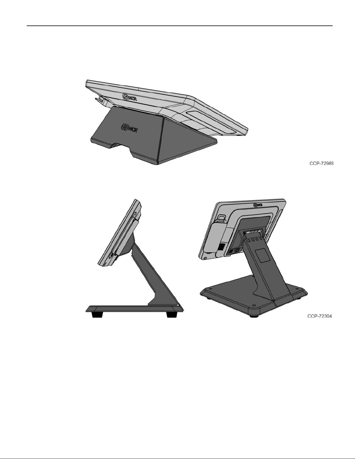
XL10W Wedge Stand (5910-F030/K030)
XL–Series Stand (5910-F033, 5910-F233)
Page 19
Product Overview 1-11
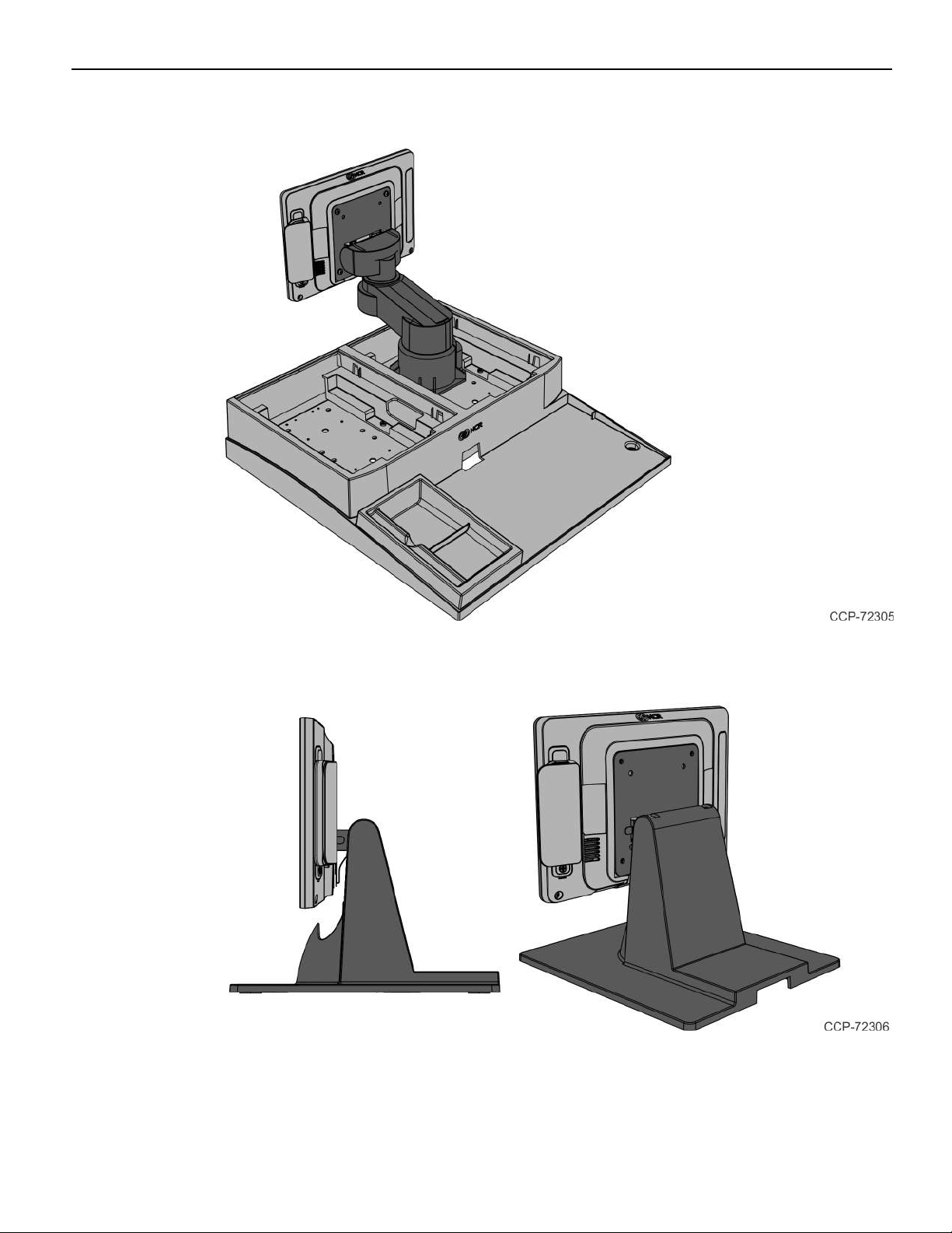
Integration Tray Mount (5968–K024)
X–Series Table Top Stand (5968–K031)
Page 20

1-12 Product Overview
Checkstand Mount (5968–K039)
WallMount (7702–K320)
Page 21

Product Overview 1-13
Third Party Mount
VESAFiller Plate (5915–K320)
Filler plate when a third party mount does not provide a sufficiently sized flat mounting
area.
Page 22

1-14 Product Overview
Magnetic Stripe Reader (5910-F141, 5910-F241)
The NCR XL10W (5910) provides an integrated 3-track ISO MSR option. The MSR is
mounted on the right side of the display. When the MSR is not installed, a cover for the
MSR location is provided. The MSR interfaces to the system via USB connection.
Data Encryption
The NCR Encrypted MSR head encrypts card data on the head using a Triple DES
DUKPT encryption scheme. The data is encrypted using the 3DES standard. A unique
3DES key is generated for every transaction (no two swipes are encrypted with the same
3DES key). The data is decrypted before it is sent to the application.
Card Data Encoding
Card data should be encoded according to the ISO Standards 7810, 7811 and 7813. In
particular, 7810 describes the physical dimensions and layout of the card and mag stripe.
7811-4, 5 and 6 relate to the locations and magnetic characteristics of track data in the
mag stripe. 7813 is specific to financial cards (credit and debit).
• Track 1 data is 7-bit encoded, alphanumeric and a maximum of 79 characters.
• Track 2 data is 5-bit encoded, numeric only and a maximum of 40 characters.
• Track 3 data is 5-bit encoded, numeric only and a maximum of 107 characters.
See the ISO Standards specifications for more detail.
Card Thickness
The MSR module accepts standard cards within the thickness range of 0.68 – 0.84 mm.
Page 23

Product Overview 1-15
Miscellaneous Kits
5910–F302/K302
Bracket to mount Non-Touch NCR XL10W (5910) to pole.
5915–K470
Bracket to mount NCR XL10W (5910) to the neck of the XLStand (5910-F033) as a
customer display. Kit includes mounting screws.
7613–K470
Bracket to mount NCR XL10W (5910) as a customer display to NCRXR3 (7613) neck.Kit
includes mounting screws.
Page 24

1-16 Product Overview
7702–K470
Bracket to mount NCR XL10W (5910) as a customer display to X-Series Stand (7702K031) or P-Series Stand (7761-K170) neck.Kit includes mounting screws.
Page 25

Product Overview 1-17
LabelLocations
Display Port Model
Page 26

1-18 Product Overview
USB-CModel
Page 27

Chapter 2: Hardware Installation
Installation Restrictions
Before installing the NCR XL10W (5910) Display, read and follow the guidelines in the
NCR XL10W (5910)Site PreparationGuide and the NCR Workstation and Peripheral
AC Wiring Guide (BST0-2115-53).
• Install the display near an electrical outlet that is easily accessible. Use the power
cord as a power disconnect device.
• Do not permit any object to rest on the power cord. Do not locate the display where
the power cord can be walked on.
• Use a grounding strap or touch a grounded metal object to discharge any static
electricity from your body before servicing the display.
Caution: This device should only be powered by a power supply source which
meets Safety Extra Low Voltage (SELV) and LPS (Limited Power Source)
requirements per UL1950, IEC 950, and EN 60 950. The power source must be
certified by the appropriate safety agency for the country of installation.
Caution: Use a grounding strap when installing this feature.
Page 28

2-20 Installation Restrictions
Ergonomic Workplace
The NCR XL10W (5910) has a high brightness LCD, please observe the following when
considering the terminal workplace:
• Avoid direct glaring and reflective glaring light. Locate the terminal in a controlled
luminance surrounding. When installed next to windows orient the terminal so it
does not reflect the outside light.
• If possible, avoid reflective glaring caused by electric light sources.
• Position the terminal for ideal viewing angles.
Page 29

Installation Restrictions 2-21
Installing the Display
The NCR XL10W (5910) Display can be mounted using a variety of mounts:
• XL10W Wedge Stand (5910-F030/K030)
• XL–Series Stand (5910–F033/K033, 5915-F233)
• XL10W Pole Mount (5910-F302/K302)
• Wall Mount (7702–K320)
• Integration Tray Mount (5968–K024)
• X–Series Table Top Stand (5968–K031)
• Checkstand Mount (5968–K039)
• Third–Party VESAMounts
This chapter explains how to perform an "Out–of–box" installation of the NCR XL10W
(5910) Display mounted on the XL–Series Stand, on the XL10W Wedge Stand, on the
XL10W Pole Mount, and how to connect cables to a POS terminal. For installation
procedures for the other mounting options see their associated kit instructions.
Page 30

2-22 Installation Restrictions
Installing the Display to the XL-Series Stand
1. Connect the Display cables and route them according to the imprinted routing
guide.
Display Port Model
a. Connect and route the Audio Cable first. Route the cable looping around the
cable strain relief posts as shown.
b. Connect the Display Power Cable and route straight down over the Audio Cable.
c. Connect the Display Port Cable and route straight down over the Audio Cable.
Page 31

Installation Restrictions 2-23
USB-C Model
a. Connect and route the USB-C Cable looping around the cable strain relief posts
as shown.
Page 32

2-24 Installation Restrictions
2. Mount the XL–Series Stand on the Display.
a. Insert the MountingBracket tabs into the slots in the rear of the Display and
then slowly rotate the stand assembly downward.
b. Rotate the Stand to the orientation shown below.
Page 33

Installation Restrictions 2-25
3. Gently push the Stand assembly forward to properly align its mounting holes with
the display. Secure the Stand with screws (2).
4. Pivot the Stand towards the back as shown.
Page 34

2-26 Installation Restrictions
5. Route and secure the Display cables to the Mounting Bracket.
Display Port Model
a. Route the Audio Cable first to the left slot and make sure it is behind the tab in
the slot.
b. Route the Display Port Cable to the left slot and make sure it is behind the tab in
the slot.
c. Route the USBCable to the right slot and make sure it is behind the tab in the
slot.
Page 35

Installation Restrictions 2-27
USB-CModel
a. Route the USB-C Cable to the right slot and make sure it is behind the tab in the
slot.
6. Route the cables through the neck slot then push cables through the curved neck
opening and then out the base opening.
Display Port Model — Align the Audio Cable and Display Port Cable to the left side
and the 12VUSBCable to the right side.
Page 36

2-28 Installation Restrictions
USB-CModel — Align the USB-CCable to the right side.
7. Pull cables such that most of the cables have been fed through the base opening.
Page 37

Installation Restrictions 2-29
8. Position the display and stand assembly in an upright position.
Installing the Display to the XL10W Wedge Stand
1. Remove the Cover from the Wedge Stand.
a. Swing the Cover upward to detach. The Cover has a snap fit connection on the
bottom.
b. Pull Cover in the direction shown to unlatch.
Page 38

2-30 Installation Restrictions
2. Connect the Display Cables and route them as shown.
Display Port Model
USB-CModel
3. Install the Wedge Stand on the back of the Display (4 screws).
Page 39

Installation Restrictions 2-31
4. Route the Cables through the slot between the tabs and make sure the Cables are
behind the tabs.
5. Reinstall the Wedge Stand Cover.
a. Insert the tabs of the Cover into the Wedge Stand.
b. Swing the Cover down until it latches into place.
6. Connect the Display Cable(s) to the host terminal.
Page 40

2-32 Installation Restrictions
Installing the Display to the XL10W Pole Mount
1. Connect the Display cables and route them according to the imprinted routing
guide.
Display Port Model
a. Connect and route the Audio Cable first. Route the cable looping around the
cable strain relief posts as shown.
b. Connect the Display Power Cable and route straight down over the Audio Cable.
c. Connect the Display Port Cable and route straight down over the Audio Cable.
Page 41

Installation Restrictions 2-33
USB-C Model
a. Connect and route the USB-C Cable looping around the cable strain relief posts
as shown.
2. Insert the cable(s) through the Bracket opening.
Page 42

2-34 Installation Restrictions
3. Install the Bracket on the back of the Display (4 screws).
4. Insert the cable(s) through the Pole.
Page 43

Installation Restrictions 2-35
5. Mount the Display on the Pole.
6. Connect the Display Cable(s) to the host terminal.
Page 44

2-36 Installation Restrictions
Connecting to a POS Terminal
The following illustrations show the host terminal cable connections.
Display Port Model
The required cables vary depending on the available video connectors on the host
terminal.
Display Port Cables
The Display Port Cable provides video to the display.
• Connect the Display Port Cable to the Display Port connectors on both the display
and the terminal.
Page 45

Installation Restrictions 2-37
ExternalPower Cables
An ExternalPower Cable provides both USBand power to the display when the host
terminal does not have a USB12V port available, but does have an available standard
USB port.
1. Connect the External Power Cable to the display Power connector.
2. Connect the other end of the ExternalPower Cable to the USBconnector on the host
terminal.
3. Connect the Power Adapter DCCable to the External Power Cable (middle of cable).
4. Connect the ACPower Cord to the Power Adapter and an ACoutlet.
Page 46

2-38 Installation Restrictions
Powered USBCables
The Powered USBCable provides both USBand power to the display.
Audio Cable
The Audio Cable provides audio to the display.
• Connect the Audio cable to the Audio Port connectors on both the display and the
terminal.
Page 47

Installation Restrictions 2-39
Adapters
HDMIto Display Port Adapter
The HDMIto Display Port Adapter allows connection of a display with Display Port to a
host terminal with an HDMIconnection. The adapter must be used with a Display Port
Cable.
1. Connect the Display Port Cable to the display.
2. Connect the other end of the Display Port Cable to the Display Port connector of the
HDMI to DisplayPort Adapter.
3. Connect the HDMIconnector of the Adapter to the HDMIport of the host terminal.
4. Connect the USB connector of the Adapter to any available USBport on the host
terminal.
Note: The HDMIto Display Port Adapter includes a USBextension cable in case the
USBcable of the Adapter is not long enough to reach the desired USBport.
Page 48

2-40 Installation Restrictions
DVI-D to HDMI Adapter
The DVI-D to HDMIAdapter allows connection of a display with Display Port to a host
terminal with a DVI connection. The adapter must be used with a Display Port Cable
and an HDMI to Display Port Adapter.
1. Connect the Display Port Cable to the display.
2. Connect the other end of the Display Port Cable to the Display Port connector of the
HDMI to DisplayPort Adapter.
3. Connect the HDMIconnector of the HDMI to Display Port Adapter to the
HDMIend of the DVI-D to HDMIAdapter.
4. Connect the DVIend of the DVI-D to HDMIAdapter to the DVI port of the host
terminal.
5. Connect the USB connector of the Adapter to any available USBport on the host
terminal.
Note: The HDMIto Display Port Adapter includes a USBextension cable in case the
USBcable of the Adapter is not long enough to reach the desired USBport.
Page 49

Installation Restrictions 2-41
Page 50

2-42 Installation Restrictions
USB-CModel
USB-CCable
The USB-C Cable provides power, video, and audio to the display.
• Connect the USB-C cable to the USB-C Port connectors on both the display and the
terminal.
Page 51

Chapter 3: Operation and Cleaning
Projected Capacitive Touchscreen
PCap touchscreens have all the benefits of normal capacitive touchscreens and more:
• Fast processing of tough information
• High sensitivity (use conductive pencils, with hands, and with thin gloves)
• Multi-touch capability (10-finger)
• High resolution
• Improved legibility and display brightness due to optimal light transmission
In addition, the technology of PCap touchscreens is characterized by significantly
higher robustness and stability than common capacitive touchscreens because the active
touch surface is located on the back side of the touchscreen instead of the front side.
Therefore, the active surface is not directly touched and does not wear off by normal
use.
Since most surface contamination do not cause interference to the touchscreen the NCR
XL10W (5910) can be used in public or severe environmental conditions.
Using the PCap Touchscreen
The PCap touchscreen responds to the lightest touches. Touching with a single finger
resembles the left mouse button. Two fingers are used to zoom IN (fingers brought
together) or zoom OUT (fingers pulled apart). Circular motion can be used to rotate an
element on the screen. This function must be supported by either the Operating System
or the application.
Touchscreen Cleaning Procedures
1. Using a soft cloth dampened with isopropyl alcohol or a mild non-abrasive soap &
water solution, gently wipe the touchscreen clean.
2. Wipe the screen and edges dry.
3. Make sure the glass and screen edges dry completely before using the unit.
4. Do not use sharp objects to clean around the edges of the touchscreen
Page 52

3-44 Operation and Cleaning
Magnetic Stripe Reader
The NCR XL10W (5910) features an ISO 3-Track Encrypted MSRhead.
The card reading is bi-directional and is mounted on the right side of the display.
Using the MSR
Swipe the card through the slot in the MSR in a quick and steady movement. The
magnetic stripe must be facing up and with the stripe in the slot.
Care of Cards
• Cards should never come in contact with liquids.
• Cards should never be bent or folded in any way.
• Cards should never come in close proximity of a magnetic field.
Card Thickness
The MSR module accepts standard cards within the thickness range of 0.68 – 0.84 mm.
Page 53

Operation and Cleaning 3-45
Cabinet Cleaning Procedures
1. Disconnect the unit from the power outlet before cleaning.
2. Use a cloth lightly dampened with a mild detergent.
3. Do not use alcohol (methyl, ethyl, or isopropyl) or any strong dis-solvent. Do not use
thinner or benzene, abrasive cleaners, or compressed air.
Warning: Do not use any other types of cleaners such as vinegar, solvents,
degreasers, or ammonia-based cleaners. These can damage the unit.
4. Avoid getting liquids inside the unit. If liquid does get inside, have a qualified service
technician check it before you power it on again.
5. Remove external dust around the vents.
Page 54

Chapter 4: NCR Software OSD Utility
Introduction
The NCR Software OSD is an application that is used to adjust display parameters, such
as brightness, contrast, and color. It also provides monitor identification information,
such as the name, serial number, and manufacturer.
Supported Features
Note: Not all features are supported on every monitor. The button is inactive and
grayed out when the feature is not supported
• Brightness
• Contrast
• V Position
• H Position
• Phase
• Clock
• Red/Green/Blue Video Gain
• Color Temperature
• Auto Setup
• Restore Default Settings
• V Moire
• H Moire
• V Size
• H Size
Page 55

4-47 NCR Software OSD Utility
Installing the Utility
1. Download the OSD Utility from the NCR website: http://www.ncr.com
a.
At this site, select the Support tab.
b.
Select Drivers and Patches → Retail Support Files→ NCR RealPOS and
Peripherals→ Displays→ 5910.
c. Download the application.
There are several versions to choose from. There are GUI versions that are used to
run locally on each system or Console versions for customers who want to run the
application from a Command Line to many systems concurrently.
Windows
• NCR_Software_OSD_GUI_x86 - (32-Bit)
• NCR_Software_OSD_Console_x86 - (32-Bit)
• NCR_Software_OSD_GUI_x64 - (64-Bit)
• NCR_Software_OSD_Console_x64 - (64-Bit)
Linux
• NCR_Software_OSD_GUI_x86 - (32-Bit)
• NCR_Software_OSD_Console_x86 - (32-Bit)
2. Click on the version of choice and Save it on your local system.
3. Unzip the application to a folder of your choice on the target system.
4. In the unzipped folder, navigate to the OSD executable.
Example: (32-Bit GUI version)
NCR_Software_OSD_GUI_x86_V2.1.7.1 >> x86
5. Run the *.exe file.
NCR_Software_OSD_GUI_x86.exe >> [Enter]
6.
Answer Yes at the Security warning.
Page 56

NCR Software OSD Utility 4-48
Running the Utility (GUI Version)
1. Unzip the application to a folder of your choice on the target system.
2. In the unzipped folder, navigate to the OSD executable.
Example: (32-Bit version)
NCR_Software_OSD_GUI_x86_V2.1.6.3>> x86
3.
Execute the NCR_Software_OSD_GUI_x86.exe file to start the application.
4.
Answer Yes at the Security warning.
Main Menu
Monitors Detected Panel
This panel lists all the monitors connected to the system. If more than one monitor is
connected, the first monitor is selected by default.
Center Panel
The Center Panel displays information pertaining the selected control.
Page 57

4-49 NCR Software OSD Utility
Control Buttons
The Control Buttons show the available features that can be modified. Unavailable
features are grayed out.
Refresh
Refreshes data in the Monitors Detected panel (OSD does not auto detect). Use this
button after connecting a new monitor to refresh the data.
About
Displays a brief description of the utility.
Help
Opens the Help File.
Close
Closes the OSD application.
Information
Provides information about the selected monitor. Information includes:
• Device manufacturer
• Date manufactured
• EDID version
• Input type
• Dimensions
• Monitor name
• Monitor serial number
• Preferred timing
• Controller type
• Firmware level
• Firmware version (for Dynamo display only)
• Display mode (for Dynamo display only)
• Timing Report
• Horizontal frequency
• Vertical frequency
• Timing status
• Raw EDID
• Raw capabilities string (CAPS)
Page 58

NCR Software OSD Utility 4-50
Brightness
Provides tools for adjusting Display brightness settings.
Contrast
Provides tools for adjusting Display contrast settings.
Positioning
Provides tools for gradually moving the image on the Display to a specific region
(either left, right, up, or down).
Size
Provides tools for increasing or decreasing the height and width of the image on the
Display.
Phase
Provides tools for increasing or decreasing the phase shift of the sampling clock.
Clock
Provides tools for increasing or decreasing the video sampling clock frequency.
Colour
Provides tools for adjusting Display color settings.
Sharpness
Provides tools for increasing or decreasing the sharpness settings of the Display.
Restore
Provides the following functions:
• Auto Setup — sets horizontal position, vertical position, clock and phase
• Auto Color — sets red/green/blue gain
• Factory Defaults — restores all factory defaults including brightness, contrast,
and color
• Brightness/Contrast — restores factory defaults for brightness and contrast
• Geometry Settings — restores factory defaults for geometry settings such as
horizontal position and vertical position
• Colour Settings — restores factory defaults for colour settings
Degauss
Provides tools for CRT display to perform a degauss cycle.
Moire
Provides tools for increasing or decreasing the vertical or horizontal moiré picture
cancellation.
Page 59

4-51 NCR Software OSD Utility
Language
Provides listing of the supported languages and permits changing the OSD
language.
Display Adjustment Procedures
The adjustment procedures are similar for most features. The color adjustment shown
below is an example.
1.
Select the Colour button.
2. The default Colour Settings menu has the 6500K radio button selected. To activate
the color slides select User1.
3. Drag the slider to the right to increase the value of the property or to the left to
decrease it. Alternatively, you can click on the "+" and "-" buttons.
Page 60

NCR Software OSD Utility 4-52
Resetting Factory Defaults
Should the need arise the display settings can be reset to the factory defaults.
1.
Select the Restore button.
2. All settings or just specific groups can be reset. Select the button of choice in the
Restore window:
• Auto Setup — re-positions the window in the center of the display
• Factory Defaults — resets everything to the factory defaults
• Brightness/Contrast — resets the brightness and contrast settings only
• Color Settings — resets the color settings only
Page 61

4-53 NCR Software OSD Utility
Running the Utility (Console Version)
1. Unzip the downloaded application to a folder of your choice on the target system.
2. In the unzipped folder, navigate to the OSD executable.
Example: (32-Bit version)
NCR_Software_OSD_Console_x86_V2.1.7.1 >> x86
3. Open a Command Line dialog window.
4. From the Command Line dialog, navigate to the OSD executable (*.exe) file.
5. Execute the file to start the application.
NCR_Software_OSD_Console_x86.exe >> [Enter]
A list of the available script command options are displayed, followed by several
example scripts. If you need further assistance with creating scripts please contact
your NCR representative for help.
 Loading...