


WorldMark 4300 Server
Management
Product Manual
Release 2.0
BD20-1398-B000
12/97

The product described in this book is a licensed product of NCR Corporation.
LANDesk Server Manager is a registered trademark of Intel Corporation, WorldMark is a trademark of NCR
Corporation, UNIX is a registered trademark of the United States and other countries, exclusively licensed through
X/OPEN Company Limited, Windows NT is a registered trademark of Microsoft Corporation.
It is the policy of NCR Corporation (NCR) to improve products as new technology, components, software, and
firmware become available. NCR, therefore, reserves the right to change specifications without prior notice.
All features, functions, and operations described herein may not be marketed by NCR in all parts of the world. In
some instances, photographs are of equipment prototypes. Therefore, before using this document, consult with
your NCR representative or NCR office for information that is applicable and current.
To maintain the quality of our publications, we need your comments on the accuracy, clarity, organization, and
value of this book.
Address correspondence to:
Systems Information
NCR Corporation
13325 Platt Springs Road
West Columbia, SC 29170
Copyright © 1997
By NCR Corporation
Dayton, Ohio U.S.A.
All Rights Reserved

Table of Contents
Preface
Who Should Read This Book.................................................................................................................................v
Releases Covered in This Book..............................................................................................................................v
What You Need to Know .......................................................................................................................................v
How to Use This Book ...........................................................................................................................................v
Notational Conventions.........................................................................................................................................vi
Related Documentation .........................................................................................................................................vi
Chapter 1
Overview
About the Server Management Board.........................................................................................................................1-1
Components.........................................................................................................................................................1-2
Monitored/Controlled Attributes ................................................................................................................................1-3
Chapter 2
User Interface
Overview ....................................................................................................................................................................2-1
Main Screen.........................................................................................................................................................2-1
Information Groups .............................................................................................................................................2-2
Types of Attributes..............................................................................................................................................2-2
In-band Connection ....................................................................................................................................................2-4
Out-of-band Connection .............................................................................................................................................2-5
Configuring the Modem for an Out-of-Band Connection....................................................................................2-6
Server Configuration Group .......................................................................................................................................2-9
Available Attributes...........................................................................................................................................2-10
Server Administration Group....................................................................................................................................2-11
Available Attributes...........................................................................................................................................2-12
Server Status Group..................................................................................................................................................2-14
Available Attributes...........................................................................................................................................2-15
Setting Thresholds.............................................................................................................................................2-16
SMB Configuration Group .......................................................................................................................................2-18
Available Attributes...........................................................................................................................................2-18
SMB Administration Group......................................................................................................................................2-20
Available Attributes...........................................................................................................................................2-20
Updating the Firmware......................................................................................................................................2-21
SMB Security Administration Group........................................................................................................................2-23
Available Attributes...........................................................................................................................................2-23
SMB Status Group....................................................................................................................................................2-24
Available Attributes...........................................................................................................................................2-24
Events Group............................................................................................................................................................2-25
Available Events................................................................................................................................................2-25
Configuring Events...................................................................................................................................................2-28
How You Are Notified ......................................................................................................................................2-28
Configuring Alerts.............................................................................................................................................2-28
WorldMark 4300 Server Management Product Manual i

Contents
Event Actions....................................................................................................................................................2-30
Configuring Event Actions ...................................................................................................................................... 2-32
Working With Event Actions................................................................................................................................... 2-35
Testing Configured Event Actions....................................................................................................................2-35
Deleting Action Events.....................................................................................................................................2-35
Chapter 3
Service
Overview.................................................................................................................................................................... 3-1
Precaution........................................................................................................................................................... 3-1
Replacing the SMB.................................................................................................................................................... 3-2
Tools Needed...................................................................................................................................................... 3-2
Power Subsystem................................................................................................................................................3-2
Removing the Board........................................................................................................................................... 3-4
Installing the Board.............................................................................................................................................3-4
LEDs................................................................................................................................................................... 3-4
Replacing the Internal Modem................................................................................................................................... 3-5
Tools Needed...................................................................................................................................................... 3-5
Removing the Modem......................................................................................................................................... 3-5
Installing the Modem.......................................................................................................................................... 3-5
Using an External Modem ......................................................................................................................................... 3-6
Appendix A
SMB Event Code Tables
Types of Events .........................................................................................................................................................A-1
Chassis-Specific Single Byte Events..........................................................................................................................A-2
SMB Firmware Events...............................................................................................................................................A-3
SMB Hardware Events ..............................................................................................................................................A-4
SMB POST Events....................................................................................................................................................A-5
Chassis Events ...........................................................................................................................................................A-6
Appendix B
Troubleshooting
Diagnostics ................................................................................................................................................................B-1
SMB LED Dark..................................................................................................................................................B-1
SMB LED Remains Amber for More Than 30 Seconds.....................................................................................B-1
Server Modem Does Not Answer.......................................................................................................................B-2
Modem Connects - No Password Prompt...........................................................................................................B-2
Cannot Log In To SMB Out-of-band..................................................................................................................B-3
In-band LANDesk Server Password Does Not Work.........................................................................................B-3
Dropped Out-of-band Connection ......................................................................................................................B-4
SMB Cannot Dial Out ........................................................................................................................................B-4
SMB Firmware Flash Fails.................................................................................................................................B-5
SMB Not Dialing Out To Report Critical Events...............................................................................................B-5
SMB Dialing Out - Console Notification Fails...................................................................................................B-5
SMB Dialing Out - Pager Notification Fails.......................................................................................................B-6
Cannot Reset SMB Modem................................................................................................................................B-6
Server Shut Down for Unknown Reason............................................................................................................B-7
Could Not Auto-discover Server Under LANDesk ............................................................................................B-7
Auto-discovery Never Returns............................................................................................................................B-8
Server Icon Grey or Not Shown Under LANDesk Console................................................................................B-9
Server Icon Displays - No Agents Expand .........................................................................................................B-9
Server Icon Does Not Show SMM Indicator......................................................................................................B-9
No SMB Out-of-band Transport Shown...........................................................................................................B-10
No SMB Icon Shown Under Server..................................................................................................................B-11
ii Table of Contents

Contents
Frequent Time-outs Seen When Retrieving Data .............................................................................................B-11
Historian Graphs Do Not Display.....................................................................................................................B-11
SMB Parameters Do Not Display In-band........................................................................................................B-12
SMB Parameters Do Not Display Out-of-band ................................................................................................B-13
SMB Events Do Not Occur as Expected..........................................................................................................B-14
SMB Modem Tests (Server)....................................................................................................................................B-15
SMB Modem Transport Logging (Console)............................................................................................................B-17
SMB Indication Handler Logging (Server) .............................................................................................................B-18
Out-of-band Console Test Checklist........................................................................................................................B-19
Hardware Configuration...................................................................................................................................B-19
System Configuration.......................................................................................................................................B-19
Arbiter Configuration .......................................................................................................................................B-19
Modem Configuration ......................................................................................................................................B-19
LANDesk UNIX Server Troubleshooting ...............................................................................................................B-21
LANDesk Server Operations............................................................................................................................B-21
LANDesk Server Problem Diagnosis...............................................................................................................B-22
LANDesk Problem Documentation..................................................................................................................B-28
WorldMark 4300 Server Management Product Manual iii

Contents
iv Table of Contents

The NCR WorldMark 4300 Server Management Product Manual is the reference manual for the
Server Management Board (SMB), a circuit board used to monitor and control the NCR
WorldMark 4300 family of servers, and its interface.
Who Should Read This Book
The intended audience for this guide is the system administrator and the field engineer; however,
some of the material will be of interest to the NCR Global Support Center personnel.
Releases Covered in This Book
This book covers the NCR WorldMark 4300 family of servers running NCR UNIX SVR4 MPRAS, Release 3.01.01 or later and the appropriate patches or Windows NT® 3.51 or later.
Preface
What You Need to Know
To use this guide effectively, you need to be familiar with the following:
• NCR WorldMark 4300 family of servers
• UNIX operating system
• Windows NT operating system
• Intel® LANDesk Server Manager software
How to Use This Book
The purpose of this book is to provide the following:
• An overview of the Server Management Board
• A description of the user interface
• Information on replacing the Server Management Board and the internal modem
This book contains the following chapters and appendixes:
Chapter 1, “Overview” contains a general description of the Server Management Board and its
uses.
Chapter 2, “User Interface” describes the server attributes that can be monitored and controlled
and gives examples of the procedures.
Chapter 3, “Service” outlines how to replace the SMB and how to replace an internal modem.
WorldMark 4300 Server Management Product Manual v

Preface
Appendix A, “SMB Event Code Tables” lists the various event codes and what they mean.
Appendix B, “Troubleshooting” describes several situations and corrective actions that you can
take.
Notational Conventions
The following conventions are used throughout this book:
• References to chapters and headings in this book and other books are enclosed in quotation
marks (“ ”). The titles of other books or manuals appear in italics.
• Commands are printed in bold type when used in text. For example: You can list all of the
software on the system by running the pkginfo utility.
• Pull-down menu commands are shown as follows:
Management <Subsystem Maintenance> <CRU/FRU Replacement>
with the top-level command in bold and lower-level options enclosed in angles brackets.
• Required elements of command strings are also enclosed in angled brackets. For example: To
list the contents of a single package, use the command
<package name>
• Directory names, file names, arguments, and fields on a screen are printed in italics. For
example, Configuration information is stored in the /etc/hosts file. Italics are also used to
distinguish variables, as in the previous example.
• Examples of screen output are printed in courier type. For example:
Do you want to continue? (Y, n)
• Text that you must enter exactly as shown is printed in
cmicHelp
.
• Menu buttons are shown in UPPERCASE letters. For example: Select MODIFY and then
select APPLY.
• Key names are printed in bold type. For example: Press Enter.
• Numbered lists denote specific order; lists with bullets do not denote any order.
is the name of the specific package.
pkginfo -l <
bold courier
package name
, where
>
type. For example:
Related Documentation
For more information on the NCR WorldMark 4300 family of servers, consult the following:
Model 4300 Deskside
• WorldMark 4300 Deskside Installation Roadmap (BST0-2142-5400)
• WorldMark 4300 Deskside Quick Hardware Installation (BST0-2139-6300)
• Server Software Guide (4SMP) (B003-0108-A000)
• WorldMark 4300 Deskside Product Guide (B003-0175-A000)
• System Site Log (B003-0174-A000)
WorldMark 4300 Installing MP-RAS (BST0-2139-6400)
•
• WorldMark 4300 Installing Windows NT Server (BST0-2139-6500)
vi Preface

Preface
• WorldMark 4300 Site Preparation Guide (B003-0156-A000)
• AMIDiag User’s Guide (BST0-2141-1300)
• AMIDiag Supplement (4SMP) (B003-2139-5700)
• WorldMark 4300 Deskside Service Guide (BST0-2139-5500)
Model 4300 Rack Mount
• WorldMark 4300 Rack Mount Product Guide (B003-0207-A000)
• WorldMark 4300 Rack Mount Hardware Installation Guide (B003-0209-A000)
• WorldMark 4300 Rack Mount Site Preparation Guide (B003-0208-A000)
• WorldMark 4300 Universal Rack Supplement (B003-0102-A000)
• WorldMark 4300 Installing MP-RAS (BST0-2139-6400)
• WorldMark 4300 Installing Windows NT Server (BST0-2139-6500)
• AMIDiag User’s Guide (BST0-2141-1300)
• AMIDiag Supplement (BST0-2139-5700)
• NCR PCI SCSI Host Adapter Service Guide (BD10-4939-A000)
• WorldMark 4300 Server Support Log (BST0-2139-5600)
• 6210 Subsystem Service Manual (BD20-1354-A000)
• Installing and Servicing the 6257 Disk Array Subsystem (BST0-2140-9000)
• Series 4 Disk Array Subsystem User Guide Models DS-6255/RM-6250 (BST0-2141-1500)
• Series 4 Disk Array Subsystem Service Manual Models DS-6255/RM-6250
(BST0-2141-1600)
• WorldMark 4300 Rack Mount Service Guide (B003-0210-A000)
Model 4380 Deskside
• WorldMark 4380 Deskside Installation Roadmap (B003-0162-A000)
• WorldMark 4380 Deskside Hardware Installation Guide (B003-0181-A000)
• Server Software Guide (OctaSCALE) (B003-0109-A000)
• WorldMark 4380 Deskside Product Guide (B003-0107-A000)
• System Site Log (B003-0174-A000)
• WorldMark 4300 Installing MP-RAS (BST0-2139-6400)
• WorldMark 4300 Installing Windows NT Server (BST0-2139-6500)
• WorldMark 4380 Site Preparation Guide (B003-0149-A000)
• AMIDiag User’s Guide (BST0-2141-1300)
AMIDiag Supplement (OctaSCALE) (B003-0151-A000)
•
• WorldMark 4300 Deskside Service Guide (BST0-2139-5500)
For more information on the Intel LANDesk Server Manager software, consult the NCR Server
Manager, Release 5, User Guide (BST0-2141-1100).
WorldMark 4300 Server Management Product Manual vii

Preface
viii Preface

About the Server Management Board
The Server Management Board (SMB) is a circuit board used to monitor and control an NCR
WorldMark 4300 server. It can be installed in both the rack-mount server and the deskside
server.
The SMB supports either an internal or an external modem. This provides an interface for remote
server management and dial-out alerting when the server is not functioning properly.
The SMB, with the associated Intel® LANDesk Server Manager software, enables the
monitoring and control of the NCR WorldMark 4300 server when it is:
• In-band - communications with a server using an operational network link. Online in-band
refers to a network connection when the server is running its normal operating system.
• Out-of-band - communications with a server using a phone line or modem connection.
The drawing in Figure 1-1 shows a sample of an SMB.
Chapter 1
Overview
Figure 1-1. Sample SMB
WorldMark 4300 Server Management Product Manual 1-1

About the Server Management Board
Components
The SMB has the following components:
• Flash circuitry used to reprogram the SMB firmware.
• Interface circuitry to the NCR WorldMark 4300’s I
communications port.
• Either an internal modem or an RS232 connector to be used with an external modem.
Note: Only one modem, either internal or external can be installed.
2
C control buses and RS232
1-2 Overview

Monitored/Controlled Attributes
The SMB has the capability to monitor and control various server attributes. Some attributes can
be monitored only, some attributes can be controlled only, and some can be both monitored and
controlled.
In addition to the monitoring and controlling of the NCR WorldMark 4300 server, the user can
monitor and control the SMB itself.
Most attributes can be monitored or controlled in-band; however, there are limited attributes that
can be monitored or controlled while out-of-band.
After you configure the attributes, the SMB monitors those attributes and notifies you when a
configured threshold is crossed.
Monitored/Controlled Attributes
WorldMark 4300 Server Management Product Manual 1-3

Monitored/Controlled Attributes
1-4 Overview

Overview
The user interface is accessed using Intel’s LANDesk Server Manager software. Separate paths
have been established for in-band and out-of-band hierarchies.
For information regarding the installation and use of the LANDesk Server Manager software,
refer to the Server Manager, Release 5, User Guide and the UNIX or Windows NT
documentation received with your server.
Main Screen
The main screen of the LANDesk Server Manager console is divided into three panels.
• The left panel contains a hierarchical tree structure that is used to navigate from networks to
hosts, and then to services running on that host.
• The middle panel displays the attributes of the current selection in the left panel.
• The right panel is a general purpose display area. For example, it displays graphs when a
graphable attribute is selected.
Chapter 2
User Interface
Figure 2-1. Main Screen
WorldMark 4300 Server Management Product Manual 2-1

Overview
Information Groups
Regardless of whether the operation is in-band or out-of-band, the following seven information
groups are available for viewing:
• Server Configuration
• Server Administration
• Server Status
• SMB Configuration
• SMB Administration
• SMB Security Administration
• SMB Status
The Events group is available in-band only.
The attributes in each group which are available for viewing or managing vary depending on
whether the operation is in-band or out-of-band.
Types of Attributes
All attributes are preceded by an icon that indicates certain properties.
This Icon Represents
Text strings containing monitorable information
ab
List of monitorable information
Text strings and list information that is editable by the user
ab
and
Information that can be displayed as a continuously updating graph
32
Information with a numeric value that is editable by the user
An event
2-2 User Interface

Overview
This Icon Represents
An action to be performed
Selecting an attribute and clicking the right mouse button will display a pop-up menu with the
following options:
Option Used To
Update Obtain a new value for the attribute
Edit Change the value of the attribute
(Only attributes whose icon contains a pen can
be edited.)
View Display the current value of the attribute
Description Obtain a description of the attribute
WorldMark 4300 Server Management Product Manual 2-3

In-band Connection
In-band Connection
An in-band connection is made by selecting the appropriate network, selecting the target host
within the network, and then selecting the Server Management Board Proxy icon.
Figure 2-2. In-band Connection
2-4 User Interface
Out-of-band Connection
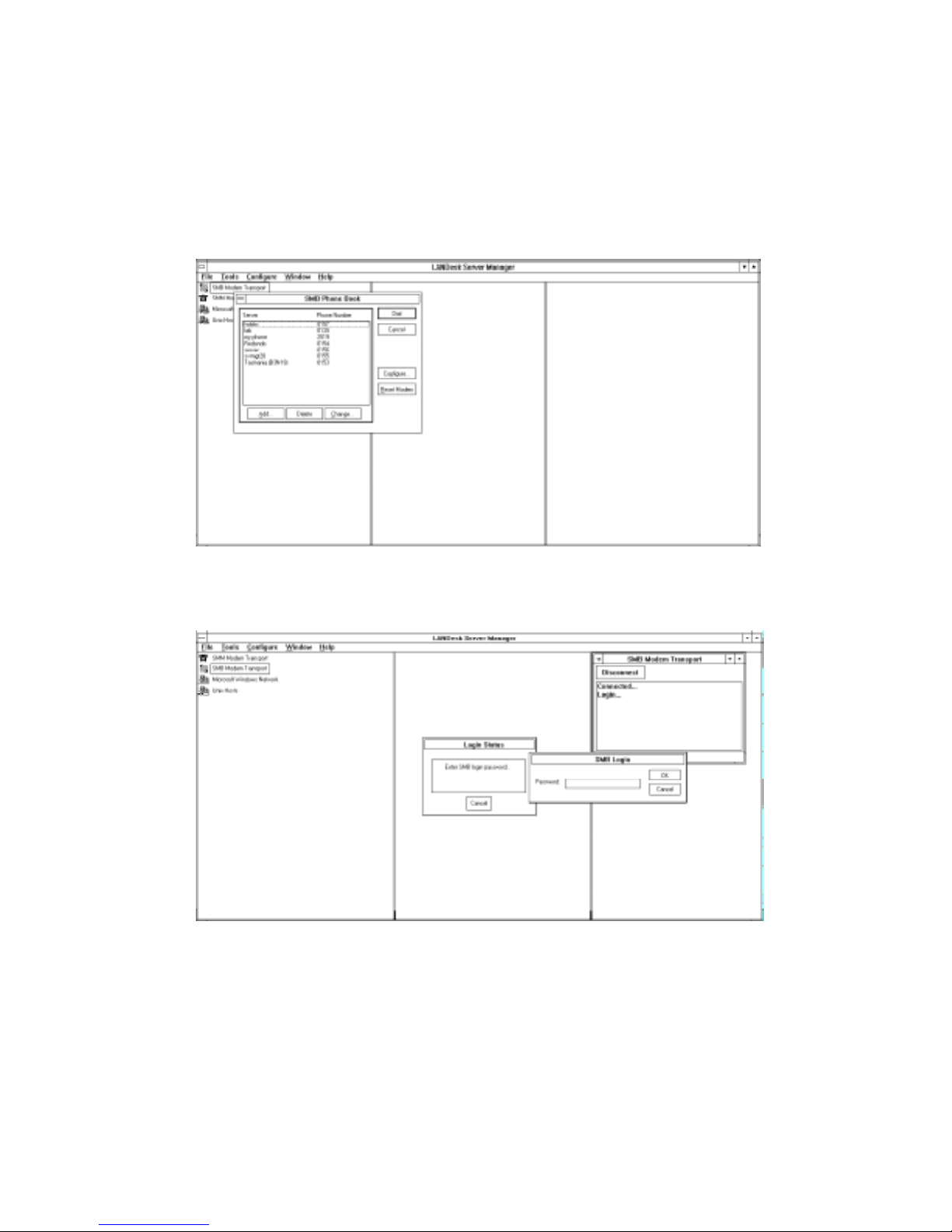
An out-of-band connection is made by selecting the SMB Modem Transport icon and then
choosing the target host from the listing displayed during the dial up process.
Figure 2-3. Dial-Up Window
Out-of-band Connection
Figure 2-4. Out-of-band Connection
Note: Before you can use the out-of-band connection, the modem attached to the console must
be configured.
WorldMark 4300 Server Management Product Manual 2-5

Out-of-band Connection
Configuring the Modem for an Out-of-Band Connection
To begin the configuration process, highlight “SMB Modem Transport” in the left pane then
select Configure from the menubar. The Configure Communications dialog box, as shown in
Figure 2-5, is displayed.
Figure 2-5. Configure Communications Dialog Box
The following table describes the fields of the Configure Communications dialog box.
Field Description
Communications Port The settings that inform the LANDesk console which modem to use.
Timeouts The setting that controls the out-of-band communication with an SMB. These
Events The settings that control how the console handles SMB-generated events.
2-6 User Interface
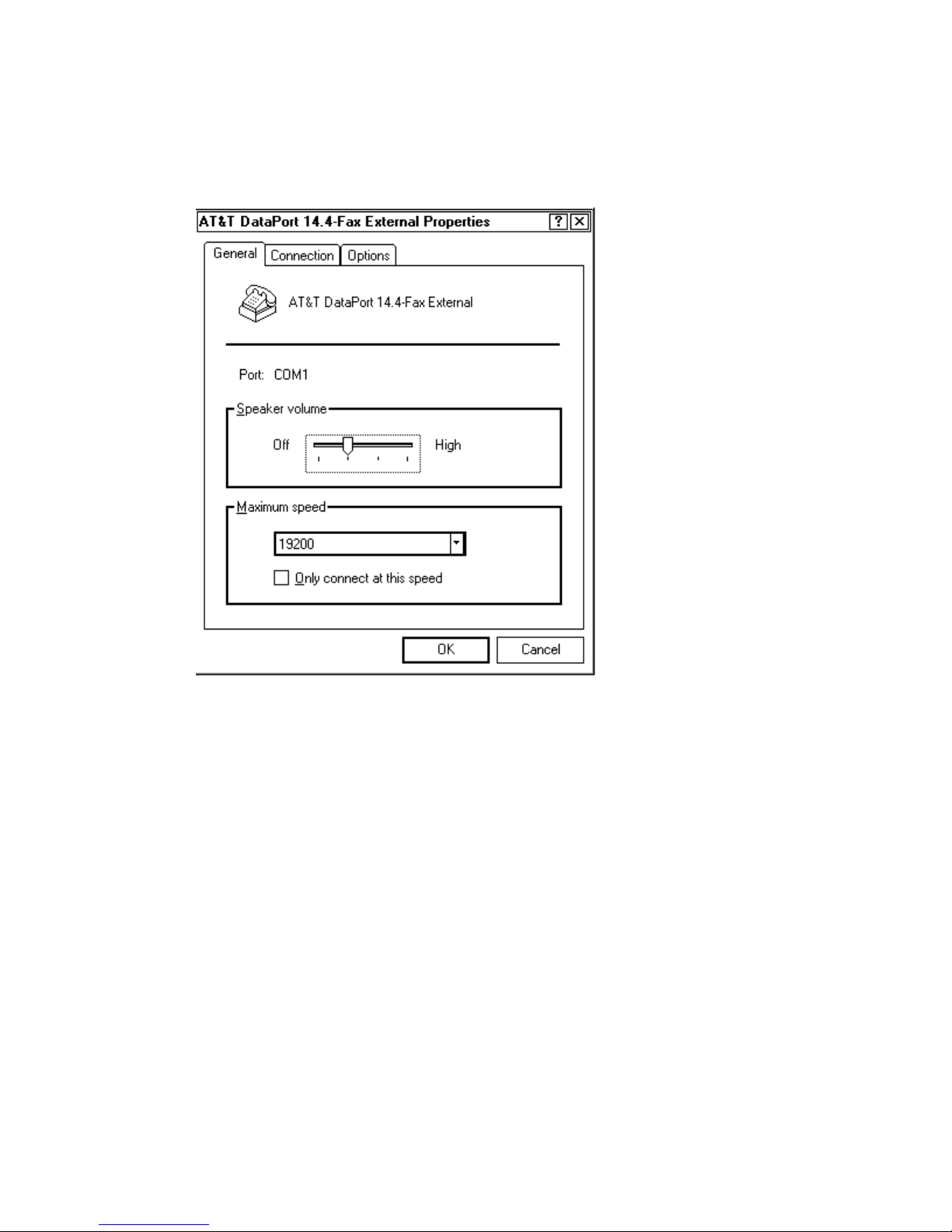
Select the MODEM button and choose the applicable modem from the dropdown list.
• On Windows NT 3.51, a dialog box is displayed giving the user full
control over the modem initialization strings.
• On Windows NT 4.0, the modem is actually configured from the Control
Panel. Refer to Figure 2-7 for a sample of the Control Panel.
The modem must be configured as detailed in the “Out-of-Band Console
Test” checklist.
should rarely, if ever, be changed.
If the “Listen For Dial-in Events” option is selected, the console modem must
be configured to answer the telephone.
Out-of-band Connection
After completing the Configure Communications dialog box, press the MODEM button. The
Configure Modem dialog box, as shown in Figure 2-6, is displayed.
Figure 2-6. Configure Modem Dialog Box
Enter the appropriate information and click OK to return to the Configure Communication dialog
box.
Click the RESET MODEM button to complete the configuration process.
WorldMark 4300 Server Management Product Manual 2-7
Out-of-band Connection
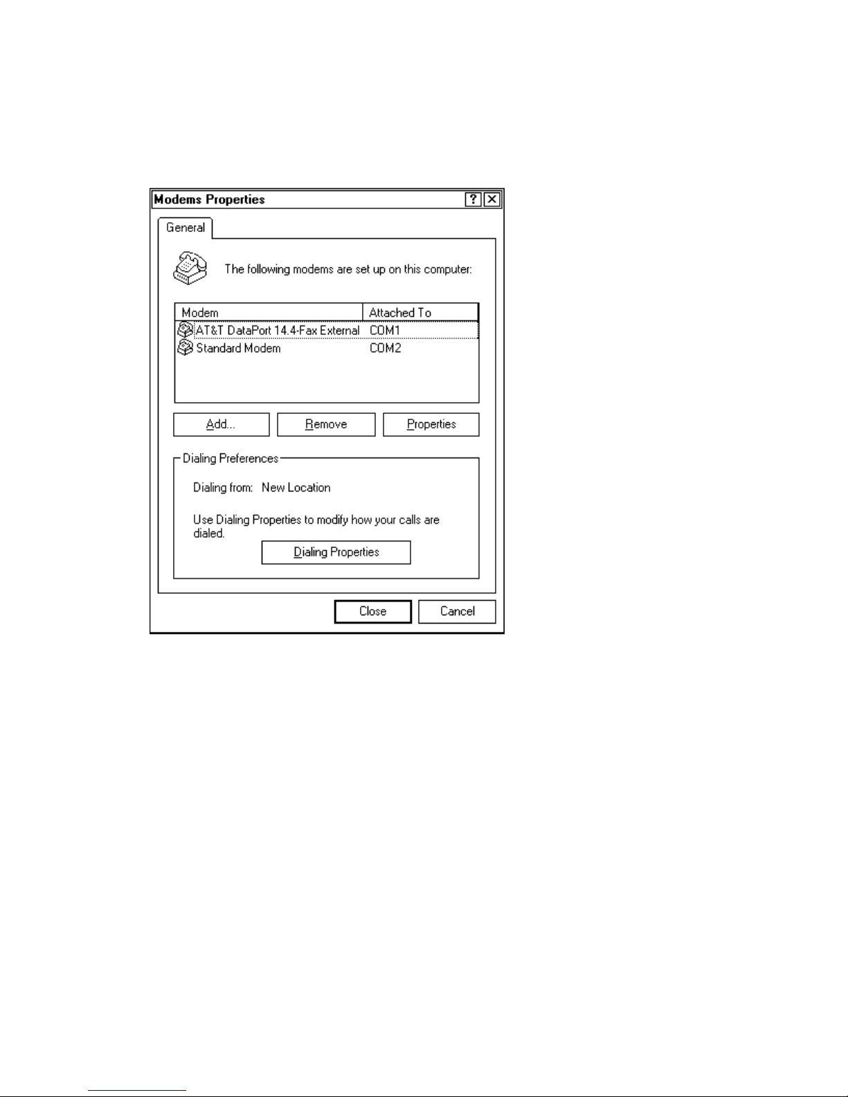
Figure 2-7 shows the screen used to install or remove modem devices on Windows NT 4.0
systems.
Figure 2-7. Control Panel
2-8 User Interface
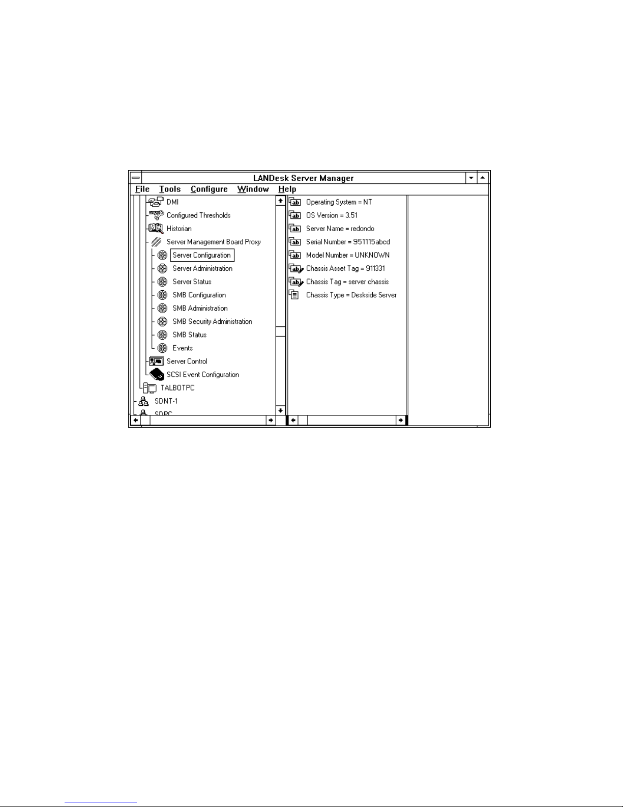
Server Configuration Group
The Server Configuration group contains attributes related to the configuration of the server
itself.
Figure 2-8. Server Configuration Group
Server Configuration Group
WorldMark 4300 Server Management Product Manual 2-9

Server Configuration Group
Available Attributes
The following attributes are available on the Server Configuration group:
Attribute Description
Operating System Name of the OS
OS Version Version number of the OS
Server Name Server’s network name or phone book name
Serial Number Serial number of the server chassis
Model Number Model number of the server chassis
Chassis Asset Tag Customer-supplied asset tag for the server
Chassis Tag Customer-supplied description of the chassis
Chassis Type Type of chassis (i.e., unspecified server node,
(In-band only)
(In-band only)
deskside server, rack-mount node)
2-10 User Interface
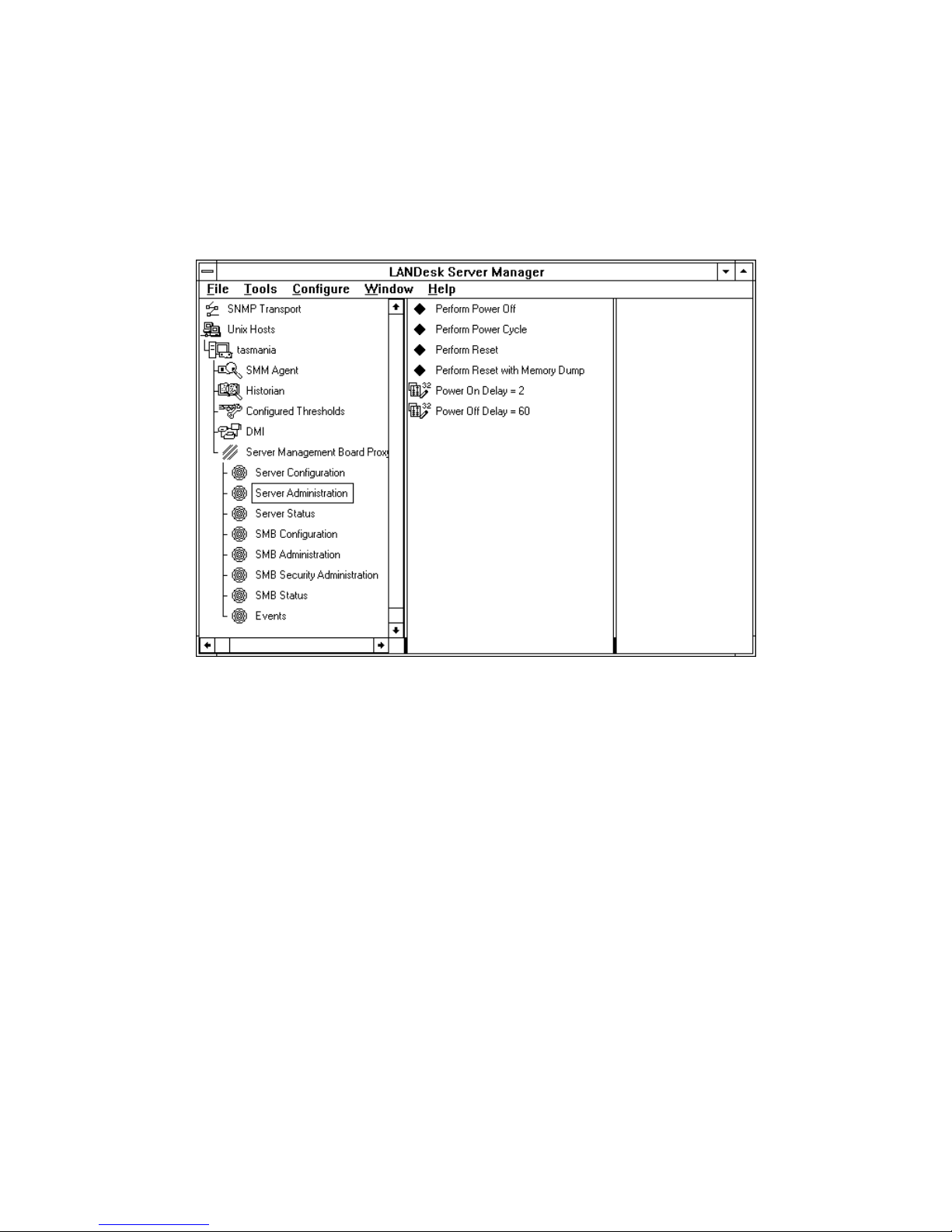
Server Administration Group
The Server Administration group is used to request a specific operation be performed by the
server.
Figure 2-9. Server Administration Group
Server Administration Group
WorldMark 4300 Server Management Product Manual 2-11

Server Administration Group
Available Attributes
The following attributes are available on the Server Administration group:
Attribute Description
Perform Power On Powers on the server.
Perform Power Off Requests a shutdown of the OS, if operable, and powers off the
Perform Power Cycle Requests a shutdown of the OS, if operable, and momentarily
Perform Operating
System Reboot
Perform Reset Requests a shutdown of the OS, if operable, and reboots the server
Perform Reset with
Memory Dump
Power On Delay Sets the length of time (in 10-second increments) the server delays
Power Off Delay Sets the length of time (in 10-second increments) the server delays
(Out-of-band only)
server after the OS is shutdown or after the power off delay is
reached.
powers off the server after the shutdown or the power off delay is
reached. The server should reboot and return to service
automatically.
Requests a reboot of the OS. The reboot is performed by the inband agent.
(Out-of-band only)
after the shutdown or the power off delay is reached. The server
should return to service automatically.
Copies memory to the dump partition, shuts down the OS, and
reboots. The server causes the system to generate a non-maskable
interrupt and reset. If the OS is operable and supports it, the NMI will
cause an image of memory to be written to the configured dump
area prior to the reset. This option is typically used only for
debugging purposes.
prior to performing a power on.
prior to performing a power off. An appropriate value is configured by
the SMB firmware and the value should not be changed.
Selecting an attribute and clicking the right mouse button will display a pull-down menu that
gives you the option to perform the action or display additional information about what will
happen if the action is performed.
2-12 User Interface

Server Administration Group
Figure 2-10. Sample Pull-down Menu
Selecting <Perform Action> displays a pop-up window in which you can confirm that you want
to perform the action.
Figure 2-11. Sample Pop-up Window
WorldMark 4300 Server Management Product Manual 2-13
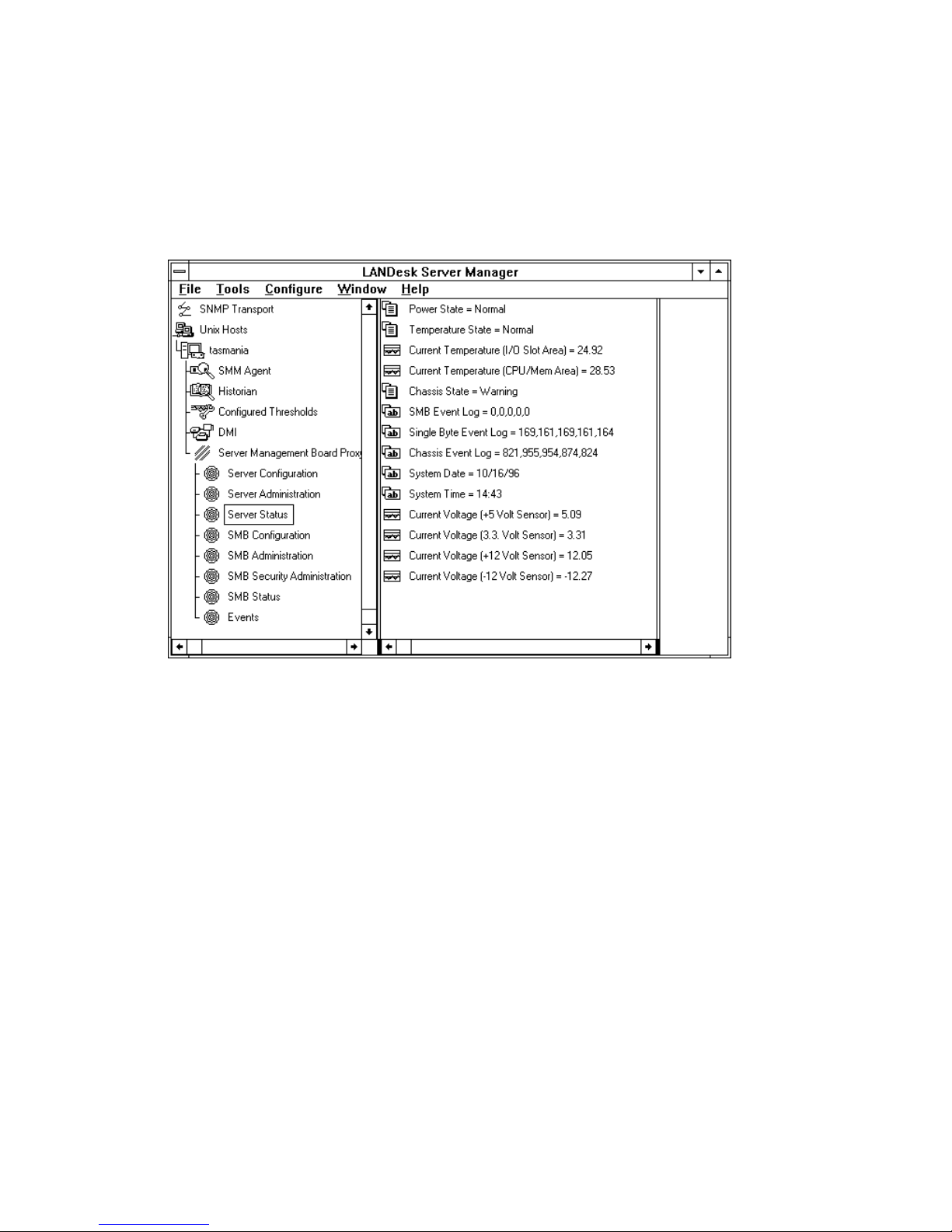
Server Status Group
Server Status Group
The Server Status group contains attributes that provide information regarding the current state
of the server.
Figure 2-12. Server Status Group
2-14 User Interface

Available Attributes
The following attributes are available on the Server Status group:
Attribute Description
Power State Power state of the server chassis which is based on the system voltages
Temperature State Thermal state of the server chassis which is based on the system
Current Temperature
(I/O Slot Area)
Current Temperature
(CPU/Mem Area)
Chassis State State of the server chassis which is based on the combined power state,
SMB Event Log Last 5 critical events, from least recent to most recent, logged on the SMB
Single Byte Event Log List of the single byte event values, from least recent to most recent, stored
POST Codes List of power on self test codes
Chassis Event Log List of event codes, from least recent to most recent, from the SMB event log
System Date Current date at the server location
System Time Current time at the server location
Current Voltage
(+5 Volt Sensor)
Current Voltage
(3.3 Volt Sensor)
Current Voltage
(+12 Volt Sensor)
Current Voltage
(-12 Volt Sensor)
Server Status Group
versus the configured voltage thresholds and the state of the power supplies
temperature versus the configured temperature thresholds
Current temperature of the server chassis input/output slot area
(In-band only)
Current temperature of the server chassis CPU and memory area
(In-band only)
thermal state, and the state of crucial chassis components
(Associated with the SMB itself)
This log contains SMB Firmware Event and SMB Hardware Event codes, as
represented in Appendix A of this manual
in the SMB error log
(Associated with the power subsystem)
This log contains Chassis-specific Single Byte Event codes, as represented
in Appendix A of this manual
(Out-of-band only)
(All events not associated with the SMB or power subsystem)
This log contains Chassis Event codes, as represented in Appendix A of this
manual
(In-band only)
(In-band only)
Current voltage reading from the +5 volt power supply line
(In-band only)
Current voltage reading from the 3.3 volt power supply line
(In-band only)
Current voltage reading from the +12 volt power supply line
(In-band only)
Current voltage reading from the -12 volt power supply line
(In-band only)
WorldMark 4300 Server Management Product Manual 2-15
Server Status Group
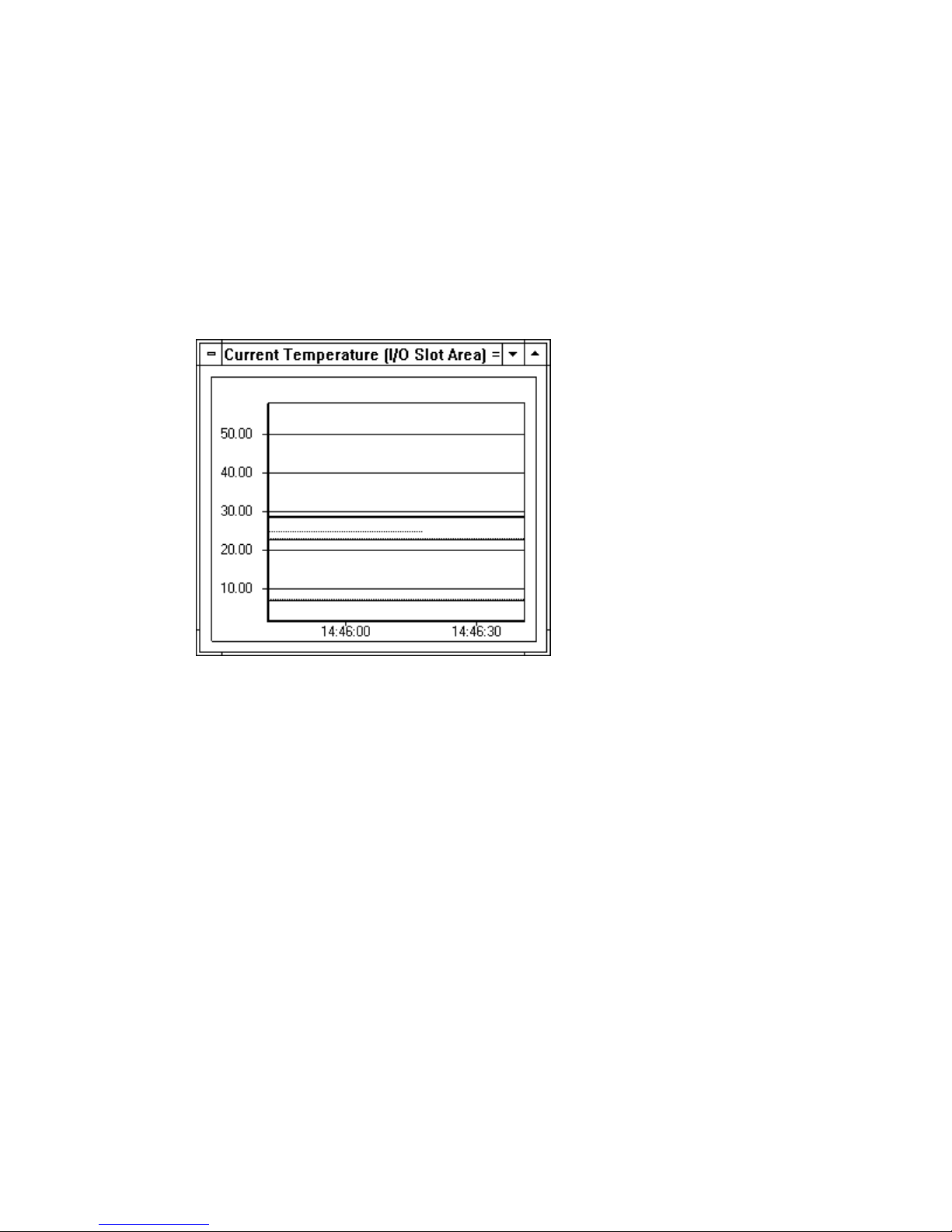
Setting Thresholds
Thresholds for the temperature and voltage values can be set as follows:
1. Double-click on the attribute value on the middle panel to display a graph, as shown in
Figure 2-13, in the third panel.
Figure 2-13. Sample Graphical Display
The three straight lines on the graph represent, from top to bottom, the High Shutdown
Threshold, the High Alarm Threshold, and the Low Alarm Threshold. The default display
colors are yellow for a warning level and red for a fatal level.
Note: When displaying the minus voltage status, the high shutdown is at the bottom of the
graph.
2. Grab the applicable straight line with the mouse and drag it up or down to a new value.
3. To set a more specific threshold, select Configure <Edit Thresholds> from the Main Screen.
A dialog box, as shown in Figure 2-14, is displayed.
4. Enter the threshold values.
5. Click OK.
2-16 User Interface
 Loading...