

Page 1

Kit Instructions
Verifone UX100, UX300, and UX400 Mount
without Trackball
7705-K055
Issue C
Page 2

The product described in this book is a licensed product of NCR Corporation.
NCR is a registered trademark of NCR Corporation. SelfServ™ is a trademark of NCR Corporation in the
United States and/or other countries. Other product names mentioned in this publication may be
trademarks or registered trademarks of their respective companies and are hereby acknowledged.
The terms HDMI and HDMI High-Definition Multimedia Interface, and the HDMI Logo are trademarks
or registered trademarks of HDMI Licensing LLC in the United States and other countries.
Where creation of derivative works, modifications or copies of this NCR copyrighted documentation is
permitted under the terms and conditions of an agreement you have with NCR, NCR's copyright notice
must be included.
It is the policy of NCR Corporation (NCR) to improve products as new technology, components,
software, and firmware become available. NCR, therefore, reserves the right to change specifications
without prior notice.
All features, functions, and operations described herein may not be marketed by NCR in all parts of the
world. In some instances, photographs are of equipment prototypes. Therefore, before using this
document, consult with your NCR representative or NCR office for information that is applicable and
current.
To maintain the quality of our publications, we need your comments on the accuracy, clarity,
organization, and value of this book. Please use the link below to send your comments.
EMail: FD230036@ncr.com
Copyright © 2017-2018
By NCR Corporation
Duluth, GA U.S.A.
All Rights Reserved
Page 3
Revision Record
Issue Date Remarks
i
A
B
C
Jul 2018 First Issue
Nov 2018 Added a screw for UX100 Ground Harness and a Gas Spring
Rod
Updated installation procedures
Feb 2019 Added notes on installation of screws and other devices
Added images for cabling and tie downs
Page 4

Verifone UX100, UX300, and UX400 Mount
without Trackball
Introduction
This kit provides components to support installation of the following Verifone® devices
to an NCR SelfServ™ 75 (7705) Kiosk:
• UX100 Personal Identification Number (PIN)Pad with Ground Harness
• UX300 Magnetic Stripe Reader (MSR)
• UX400 Near-Field Communication (NFC) Reader with Antenna and Comms Cables
The Verifone devices listed above are not included in this kit. They are purchased
separately by the customer.
This kit also includes a replacement Gas Spring Rod that supports the Fascia Assembly
when opened.
Page 5

2-2 Verifone UX100, UX300, and UX400 Mount without Trackball
Tools Required
• #2 Phillips screwdriver with torque limiter
• #7mm nut driver with torque limiter
• Flat Head screwdriver
Note: NCRrecommends to use a Long Thin Wall 7mm Nut Driver with torque limiter
to facilitate the installation of Verifone devices on the kiosk.
Page 6
Verifone UX100, UX300, and UX400 Mount without Trackball 2-3
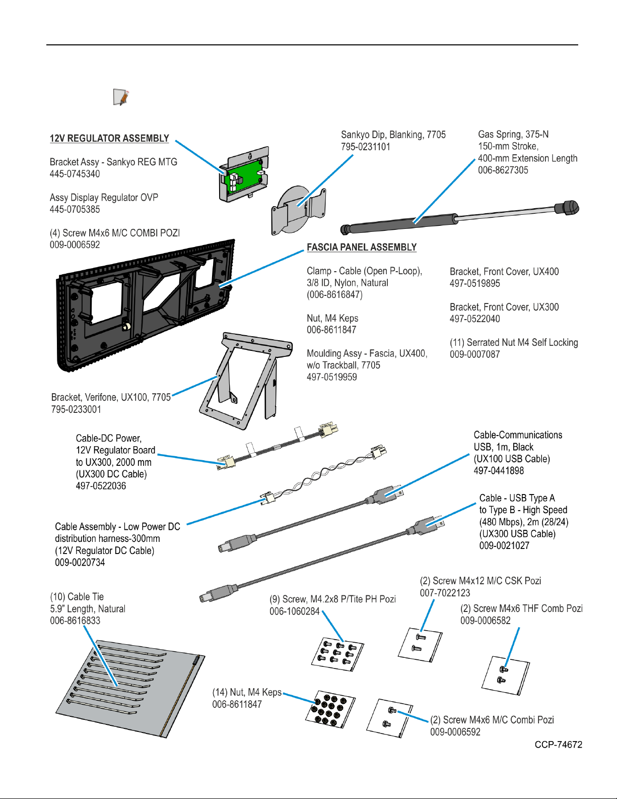
Kit Contents
Note: Depending on the kiosk configuration, some parts shown in the following image
may not be needed.
Page 7
2-4 Verifone UX100, UX300, and UX400 Mount without Trackball
Installation Procedure
Warning: Disconnect the AC power cord before disassembling the Terminal.
Caution: Static Electricity Discharge may permanently damage your system. Discharge
any static electricity build up in your body by touching your computer’s case for a few
seconds. Avoid any contact with internal parts and handle cards only by their external
edges.
Depending on the devices that are already present in the kiosk, some components of
this kit may already be installed in the kiosk and do not need to be installed again.
To install the 7705-K055 kit to a NCR Selferv™ 75 Kiosk, power down the kiosk, unplug
the power cord, and then perform the following steps:
1. Turn off the kiosk. For more information, see Turning OFF the Kiosk on page6.
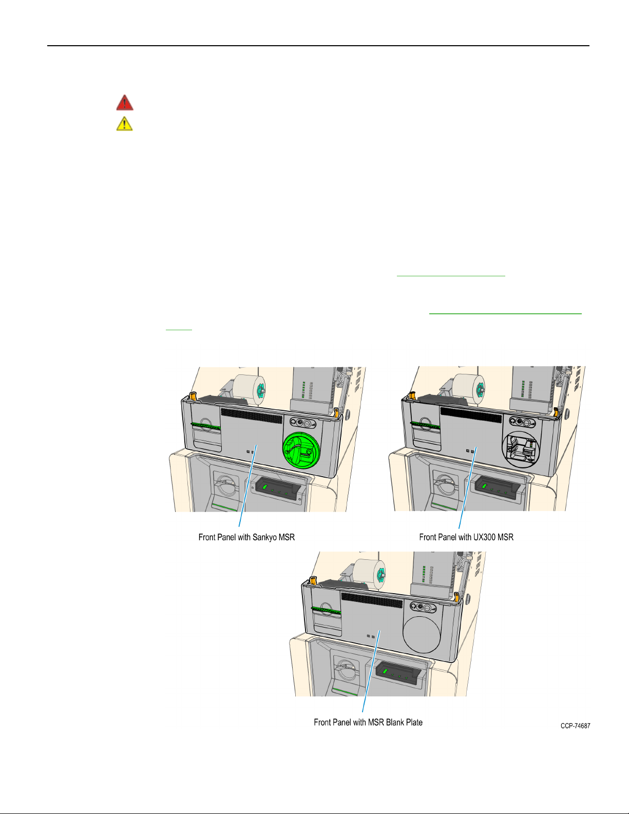
2. If the kiosk Front Panel contains an MSR, remove the MSR and install the Blank
Plate included in this kit. For more information, see Removing MSRs from the Front
Panel on page8.
Page 8
Verifone UX100, UX300, and UX400 Mount without Trackball 2-5
3. Remove the current Fascia Panel. The Fascia Panel can contain different PINpads or
a blank plate. For more information, see Removing the Fascia Panel on page34.
4. Replace the existing Gas Spring Rod. For more information, see Replacing the Gas
Spring Rod on page44.
5. Install the new Fascia Panel included in this kit. For more information, see Installing
the New Fascia Panel Assembly on page47.
6. Install the Verifone UX100 PIN Pad. For more information, see Installing the UX100
PINPad on page51.
7. In the Top Box, remove the I/OPanel Cover. For more information,see Removing the
I/O Panel Cover on page55.
8. Connect and route the device cables. For more information, see Connecting and
Routing Device Cables on page56.
9. Secure the cables. For more information, see Securing the USB, Power, and Antenna
Cables on page65.
Page 9
2-6 Verifone UX100, UX300, and UX400 Mount without Trackball
10. Install the I/OPanel Cover. For more information,see Installing the I/O Panel Cover on
page68.
11. Validate installation of Verifone UXdevices. For more information, Validating
Installation of Verifone UX Devices on page69.
Turning OFF the Kiosk
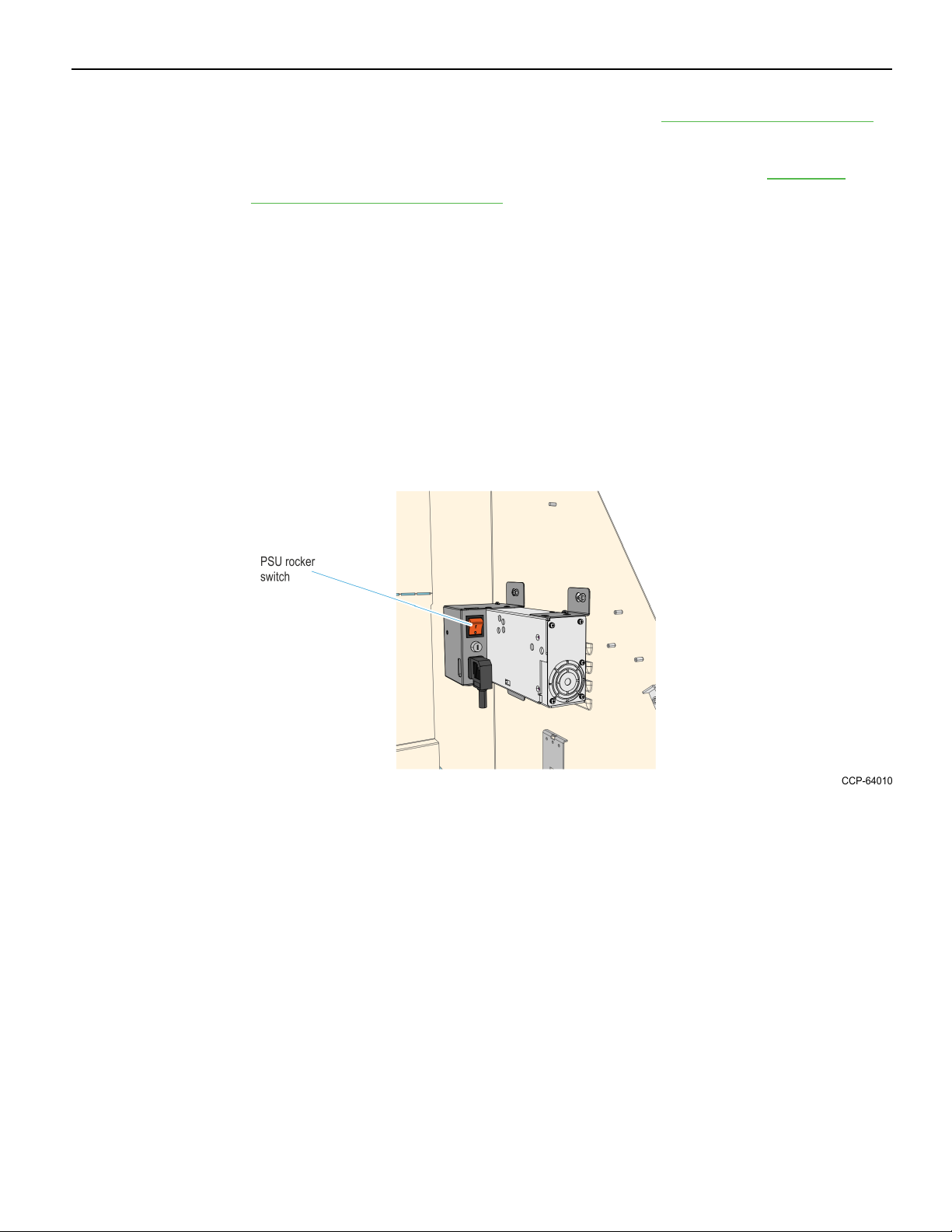
The kiosk should be switched OFF using the power switch located in the top-box,
power switch in the Sidecar if present, and the UPS power switch if present. However if
necessary, the External ACPower Cable can be used to disconnect power.
1. Exit and close Kiosk Software Application.
2. Shut down the Kiosk Operating System. At the bottom left-hand corner, select
Start→Shut down.
3. Push the Top Box PSU switch to to the "0" position.
Page 10
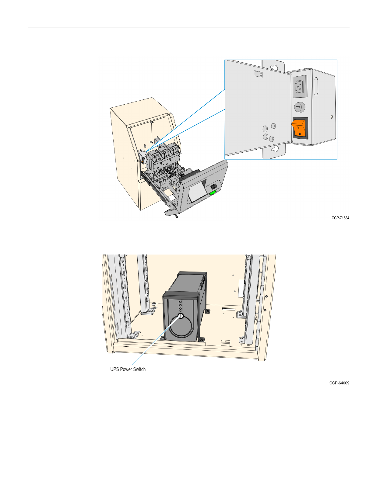
Verifone UX100, UX300, and UX400 Mount without Trackball 2-7
4. If a Sidecar is present, push the Sidecar PSU switch to to the "0" position.
5. If a UPS is present, push the power switch to shut it down.
6. Unplug the AC Power Cable from the AC power source.
Page 11

2-8 Verifone UX100, UX300, and UX400 Mount without Trackball
Removing MSRs from the Front Panel
The Front Panel can either have a Sankyo MSR or a Verifone UX300 MSR. Refer to
sections below as appropriate for the present device in the kiosk:
• Removing the Sankyo MSR from the Front Panel on the facing page
• Removing the UX300 MSR from the Front Panel on page21
Page 12
Verifone UX100, UX300, and UX400 Mount without Trackball 2-9
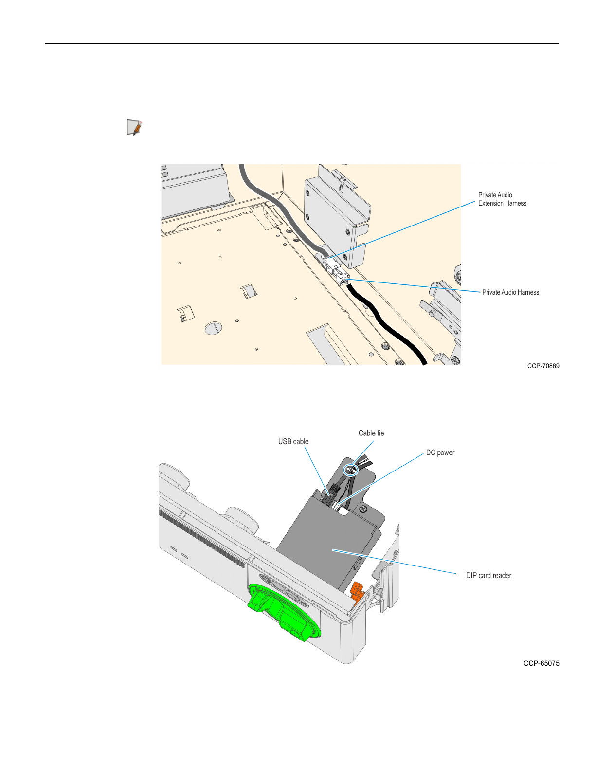
Removing the Sankyo MSR from the Front Panel
1. Inside the top box, disconnect the Private Audio Cable from the Private Audio
Extension Cable.
Note: This step is only applicable if the unit is configured with the Private Audio
feature.
2. Disconnect the USB and DC cables from the Sankyo MSR. Remove the cable ties
securing them as necessary.
3. Remove the cable ties securing the Fascia Cable Bundle, and then remove the Sankyo
USB and DC cables from the bundle.
Page 13
2-10 Verifone UX100, UX300, and UX400 Mount without Trackball
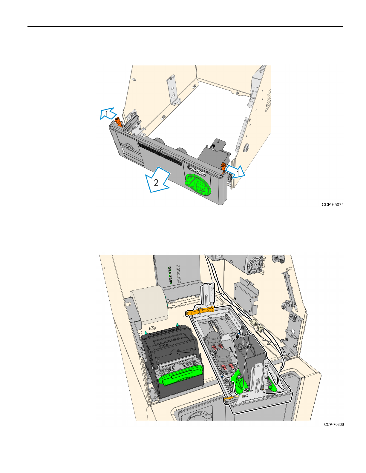
4. Slide out the Front Panel from the Kiosk. Push the two orange latches outwards and
pull the Front Panel towards you until it is out from the Kiosk.
5. Carefully place the Front Panel assembly face down on the Top Box. Note that the
Speaker Harness and Proximity Detector USBCable are still secured to the Front
Panel.
Page 14
Verifone UX100, UX300, and UX400 Mount without Trackball 2-11
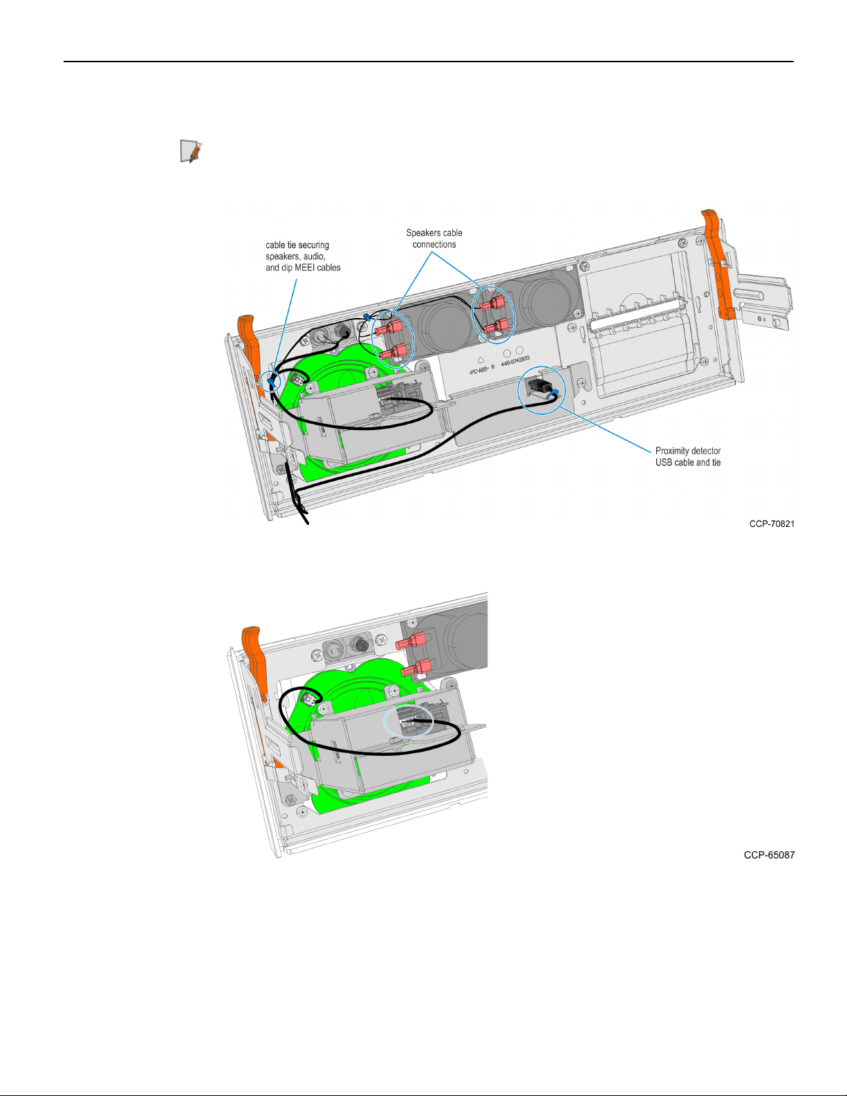
6. Take note of the routing and disconnect the Speaker Harness and Proximity
Detector USBCable, cut off the cable ties securing them to the panel.
Note: Keep the cables safe and secured in the Top Box while working on the Front
Panel.
7. Disconnect the MEEICable from the Dip MSR and MEI Ring..
Page 15
2-12 Verifone UX100, UX300, and UX400 Mount without Trackball
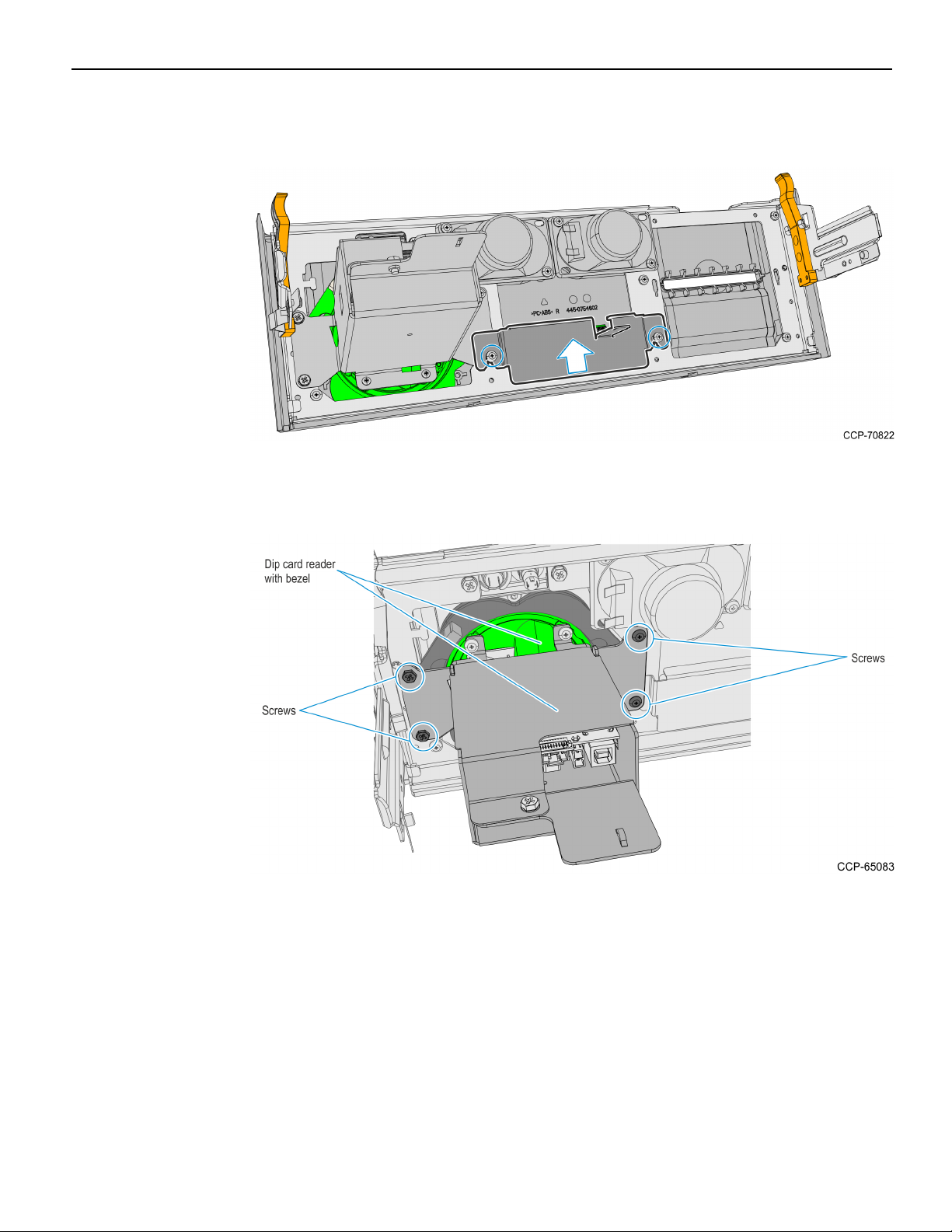
8. Remove the two screws securing the Proximity Detector Cover then remove the
cover from the Front Panel.
9. Remove the four screws securing the card reader and bezel assembly to the Front
Panel, then slide the assembly backwards to remove it from the panel.
Page 16
Verifone UX100, UX300, and UX400 Mount without Trackball 2-13
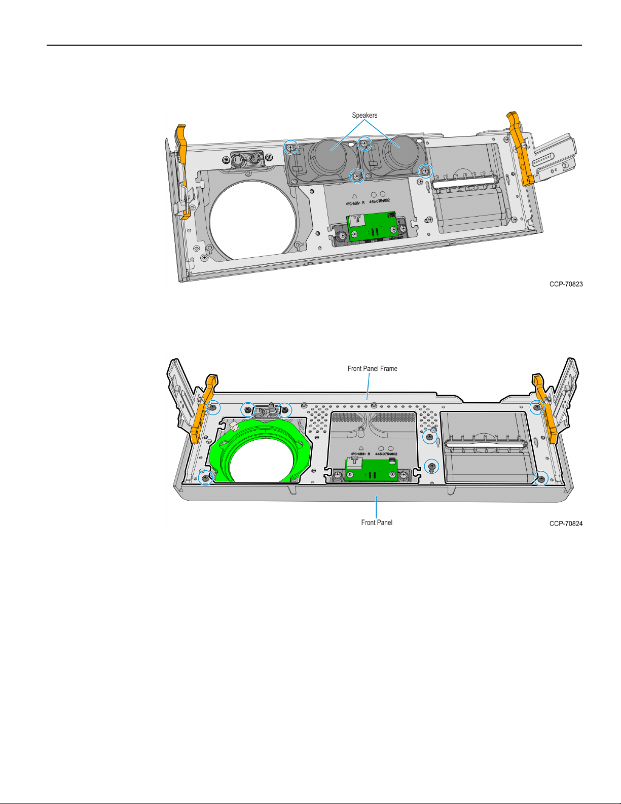
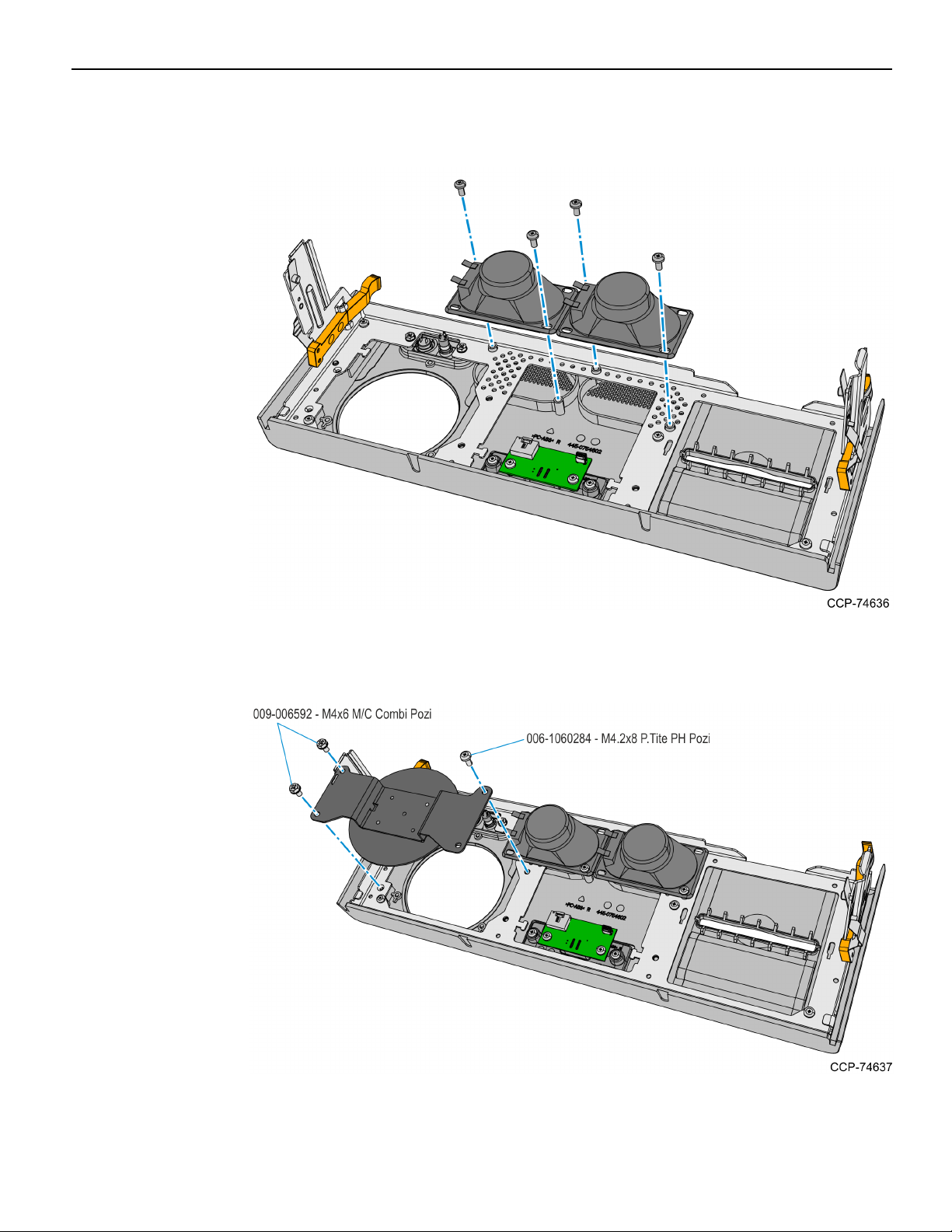
10. Remove the screws (two on each speaker) securing the Speakers to the Front Panel
then remove the Speakers.
11. Remove the eight screws securing the Panel Frame to the Front Panel then remove
the Panel Frame.
Page 17
2-14 Verifone UX100, UX300, and UX400 Mount without Trackball
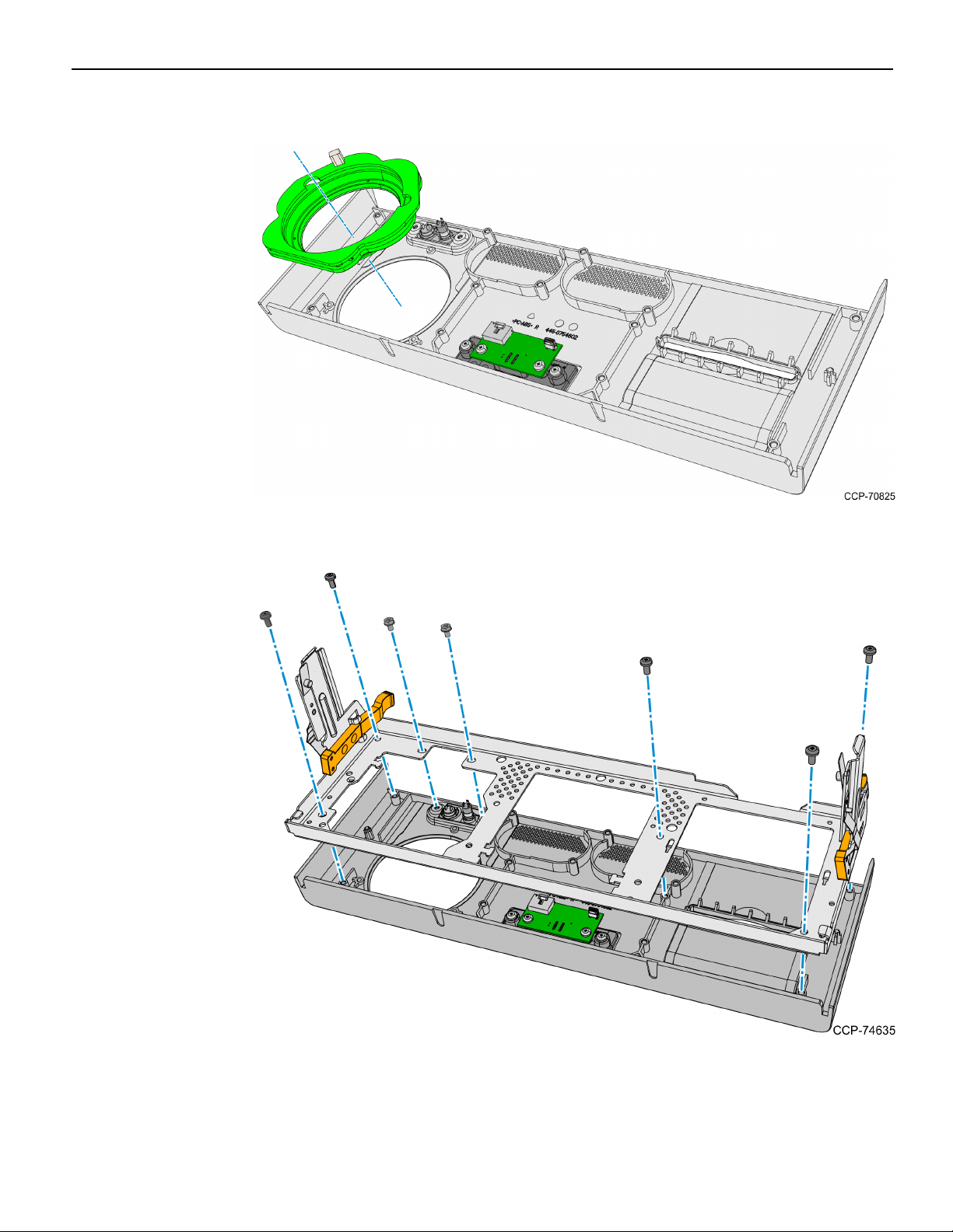
12. Remove the MSRMEIRing from the Front Panel.
13. Mount and secure the Panel Frame to the Front Panel using seven screws.
Page 18
Verifone UX100, UX300, and UX400 Mount without Trackball 2-15
14. Mount and secure the Speakers to the Front Panel using two screws on each
speaker.
15. Mount and secure the Blank Plate to the Fascia Panel using three screws. Use the
screws included in this kit and take note of the types of screws used.
Page 19
2-16 Verifone UX100, UX300, and UX400 Mount without Trackball
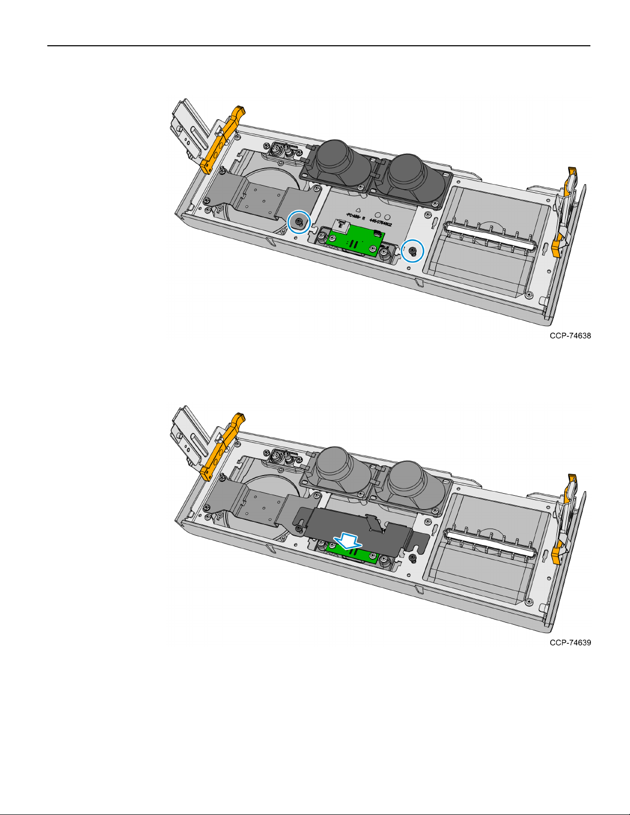
16. Mount and partially tighten two screws for the Proximity Detector Cover.
17. Insert and slide the Proximity Detector Cover under the partially tightened screws,
then fully tighten the two screws to secure the cover.
Page 20
Verifone UX100, UX300, and UX400 Mount without Trackball 2-17
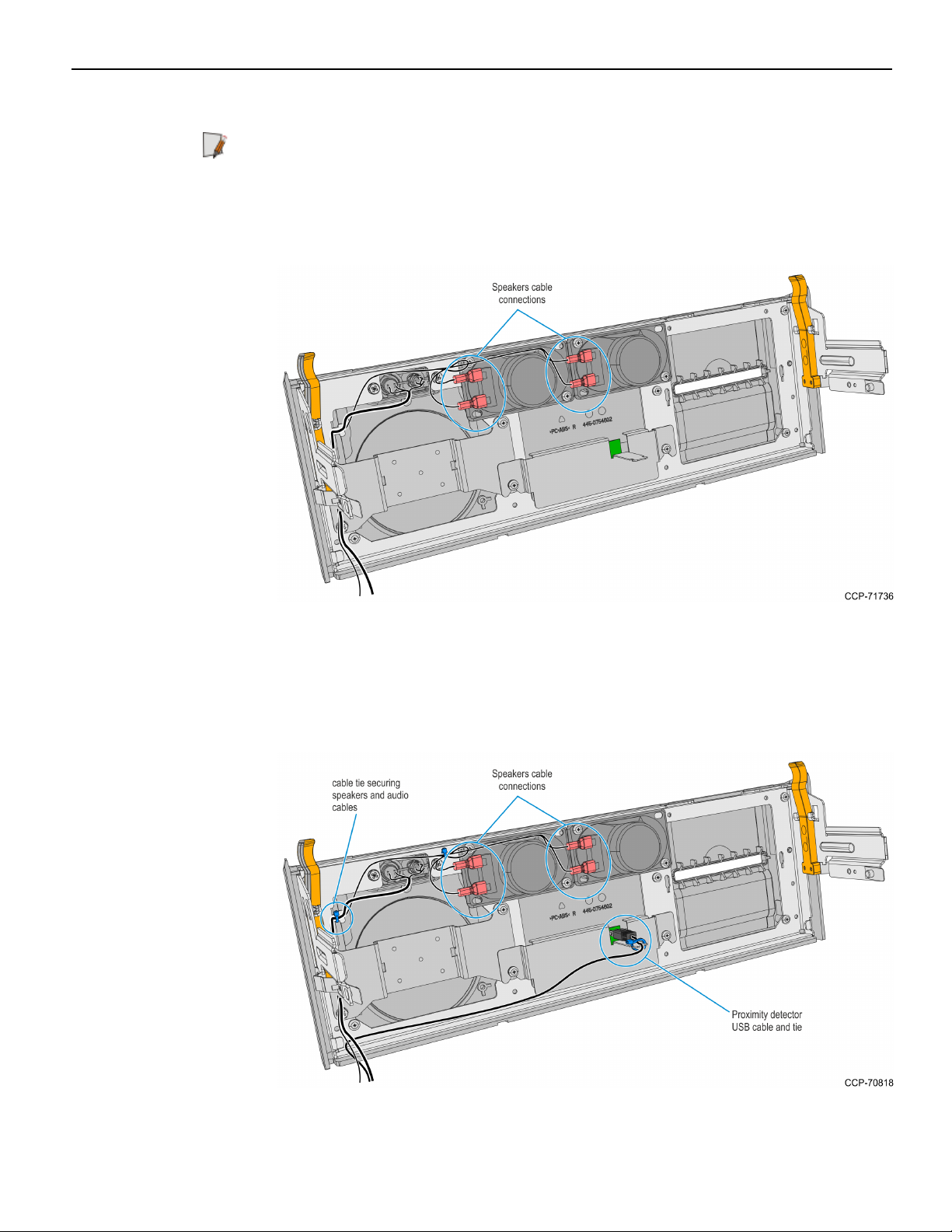
18. Connect the Speaker Cables to the Speakers.
Note: Make sure that the correct cable wire is connected to the appropriate speaker
connection terminal.
• Connect "-" cable wire to "-" speaker terminal
• Connect "+" cable wire to "+" speaker terminal
19. Route the Speaker Cables to the left-hand side of the Front Panel and secure them
with the Private Audio Cable with a cable tie.
20. Connect the Proximity Detector USBCable to the Proximity Detector Board and
secure the Cable to the Cover with a cable tie.
Page 21

2-18 Verifone UX100, UX300, and UX400 Mount without Trackball
21. Route the Proximity Detector USBCable towards the left-hand side of the Front
Panel.
22. Align the Front Panel latches to the slots in the Top Box, then push the Front Panel
into the Top Box.
23. Inside the Top Box, reconnect the Private Audio Cable to the Private Audio
Extension.
Note: This step is only applicable if the unit is configured with the Private Audio
feature.
Page 22
Verifone UX100, UX300, and UX400 Mount without Trackball 2-19
24. Remove and discard the Sankyo DIP Reader USB and DCcables.
Note: The Sankyo cables will be replaced with the following cables included in this
kit:
• Sankyo USBcable — will be replaced with the 2m UX300 USBcable (009–0021027)
• Sankyo DCcable — will be replaced with the 2m UX300 DC cable (497–0522036)
a. Disconnect the Sankyo USB cable from the USBHub or from the PC-core USB,
and then discard the cable.
b. Loosen the screw securing the 12V Regulator to the kiosk.
Page 23

2-20 Verifone UX100, UX300, and UX400 Mount without Trackball
c. Slide the 12V Regulator assembly upward and rotate backward to remove the
assembly.
d. Disconnect the Sankyo MSR DCCable from the regulator, and then discard the
cable.Removing the Fascia Panel on page34
Note: For the next procedure, refer to Installation Procedure on page4.
Page 24

Verifone UX100, UX300, and UX400 Mount without Trackball 2-21
Removing the UX300 MSR from the Front Panel
1. Inside the top box, disconnect the Private Audio Cable from the Private Audio
Extension Cable.
Note: This step is only applicable if the unit is configured with the Private Audio
feature.
2. Slide out the Front Panel from the Kiosk. Push the two orange latches outwards and
pull the Front Panel towards you until it is out from the Kiosk.
Page 25

2-22 Verifone UX100, UX300, and UX400 Mount without Trackball
3. Carefully place the Front Panel assembly face down on the Top Box. Note that the
Speaker Harness and Proximity Detector USBcable are still secured to the Front
Panel.
4. Disconnect the following cables from the UX300 MSR:
• MSRPower Cable
• MSRUSBCable
• MSRto PINPad USBCable
Page 26

Verifone UX100, UX300, and UX400 Mount without Trackball 2-23
5. Remove the cable ties securing the Fascia Cable Bundle, and then remove the MSR
cables from the bundle.
6. Take note of the routing and disconnect the Speaker Harness and Proximity
Detector USBCable, cut off the cable ties securing them to the panel.
Note: Keep the cables safe and secured in the Top Box while working on the Front
Panel.
7. Remove the two screws securing the Proximity Detector Cover then remove the
cover from the Front Panel.
Page 27

2-24 Verifone UX100, UX300, and UX400 Mount without Trackball
8. Remove the four screws securing the UX300 MSRand Bracket assembly from the
Front Panel and then remove the assembly.
9. Remove the four nuts securing the UX300 MSR to the bracket.
Note: The UX300 MSRwill be installed to the new Fascia Panel included in this kit.
Page 28

Verifone UX100, UX300, and UX400 Mount without Trackball 2-25
10. Remove the screws (2 on each speaker) securing the Speakers to the Front Panel
then remove the Speakers.
11. Remove four screws securing the Panel Frame from the Front Panel.
Page 29

2-26 Verifone UX100, UX300, and UX400 Mount without Trackball
12. Remove the UX300 MSR Bezel from the Front Panel.
13. Mount and secure the Panel Frame to the Front Panel using seven screws.
Page 30

Verifone UX100, UX300, and UX400 Mount without Trackball 2-27
14. Mount and secure the Speakers to the Front Panel using two screws on each
speaker.
15. Mount and secure the Blank Plate to the Fascia Panel using 3 screws. Use the screws
included in this kit and take note of the types of screws used.
Page 31

2-28 Verifone UX100, UX300, and UX400 Mount without Trackball
16. Mount and partially tighten two screws for the Proximity Detector Cover.
17. Insert and slide the Proximity Detector Cover under the partially tightened screws,
then fully tighten the two screws to secure the cover.
Page 32

Verifone UX100, UX300, and UX400 Mount without Trackball 2-29
18. Connect the Speaker Cables to the Speakers.
Note: Make sure that the correct cable wire is connected to the appropriate speaker
connection terminal.
• Connect "-" cable wire to "-" speaker terminal
• Connect "+" cable wire to "+" speaker terminal
19. Route the Speaker Cables to the left-hand side of the Front Panel and secure them
with the Private Audio Cable with a cable tie.
20. Connect the Proximity Detector USBCable to the Proximity Detector Board and
secure the Cable to the Cover with a cable tie.
Page 33

2-30 Verifone UX100, UX300, and UX400 Mount without Trackball
21. Route the Proximity Detector USBCable towards the left-hand side of the Front
Panel.
22. Align the Front Panel latches to the slots in the Top Box, then push the Front Panel
into the Top Box.
23. Inside the Top Box, connect the Private Audio Cable to the Private Audio Extension.
Note: This step is only applicable if the unit is configured with the Private Audio
feature.
Page 34

Verifone UX100, UX300, and UX400 Mount without Trackball 2-31
24. Remove and discard the current UX300 MSR DCCable.
Note: This cable will be replaced with the 2m UX300 DC cable (497–0522036)
included in this kit.
a. Loosen the screw securing the 12V Regulator to the kiosk.
b. Slide the 12V Regulator assembly upward and rotate backward to remove the
assembly.
Page 35

2-32 Verifone UX100, UX300, and UX400 Mount without Trackball
c. Disconnect the UX300 MSR DCCable from the regulator, and then discard the
cable.
25. Remove the I/OPanel Cover.
a. Loosen the screw that secures the I/OPanel Cover.
b. Slide the cover upward to unlatch its tabs and hooks from the I/OPanel.
Page 36

Verifone UX100, UX300, and UX400 Mount without Trackball 2-33
26. Disconnect the Front Panel UX300 cable from the USBHub, and then discard the
cable.
Note: For the next procedure, refer to Installation Procedure on page4.
Page 37

2-34 Verifone UX100, UX300, and UX400 Mount without Trackball
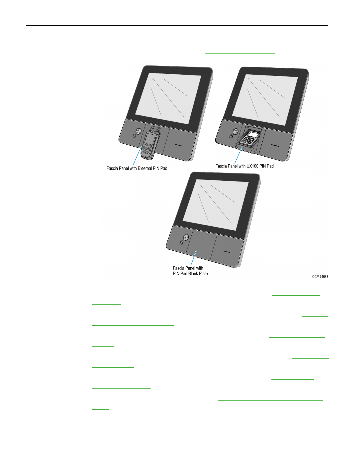
Removing the Fascia Panel
The Fascia Panel can contain different PINpads or a blank plate, refer to the sections
below as appropriate for the Fascia Panel configuration in the kiosk:
• Removing the Fascia Panel with an External PINPad on the facing page
• Removing the Fascia Panel with a UX100 PINPad on page38
• Removing the Fascia Panel with a Blank Plate on page41
Note: The Fascia Panel may also have a Trackball, which is not compatible with this kit
and will be discarded together with the panel.
Page 38

Verifone UX100, UX300, and UX400 Mount without Trackball 2-35
Removing the Fascia Panel with an External PINPad
The current Fascia Panel may contain an external PINPad and a Trackball that will be
removed and discarded in order to install this kit.
1. If a Trackball is present, disconnect the following Trackball cables:
a. USBCable from the EBox. Cut off the cable ties securing the cable to the Fascia.
b. Ground Harness from the Fascia Bracket. Remove the screw securing the harness
to the bracket.
Page 39

2-36 Verifone UX100, UX300, and UX400 Mount without Trackball
2. Disconnect the PINPad USB cable from the EBox and cut off the cable ties securing
the cable to the Fascia.
3. Remove the four nuts securing the PINPad Mounting Plate from the Fascia Panel.
Page 40

Verifone UX100, UX300, and UX400 Mount without Trackball 2-37
4. Remove the five screws securing the PINPad Bracket from the Fascia Panel.
5. Remove the screw securing the Fascia Panel to the Barcode Reader assembly.
6. Remove the six screws securing the Fascia Panel to the Main Fascia and then remove
the panel from the kiosk.
Note: For the next procedure, refer to Installation Procedure on page4.
Page 41

2-38 Verifone UX100, UX300, and UX400 Mount without Trackball
Removing the Fascia Panel with a UX100 PINPad
The following components in this procedure will be re-used to support installation of
this kit:
• UX100 PIN Pad and Bracket assembly
• PINPad Ground Harness
• PINPad USBcable
1. Remove the nut securing the PINPad Ground Harness to the PINPad.
Page 42

Verifone UX100, UX300, and UX400 Mount without Trackball 2-39
2. Remove the five screws securing the PINPad and Bracket assembly to the Fascia
Panel and then remove the assembly.
3. Cut off the cable tie securing the PINPad cable to the bracket, remove the nut
securing the cable lock bracket and then disconnect the cable from the PINPad.
Note: Keep the PIN Pad and Bracket assembly for installation to the new Fascia
Panel later. The PINPad USBcable will also be re-used to connect the UX300 MSR to
the USBHub in the Top Box I/OPanel after installing the new Fascia Panel. For
details, see Rerouting the UX100 to Front Panel UX300 USB Cable on page1.
Page 43

2-40 Verifone UX100, UX300, and UX400 Mount without Trackball
4. Remove the screw securing the Fascia Panel to the Barcode Reader assembly.
5. Remove the six screws securing the Fascia Panel to the Main Fascia and then remove
the panel from the kiosk.
Note: For the next procedure, refer to Installation Procedure on page4.
Page 44

Verifone UX100, UX300, and UX400 Mount without Trackball 2-41
Removing the Fascia Panel with a Blank Plate
The current Fascia Panel may contain a Trackball that will be removed and discarded in
order to install this kit.
1. If a Trackball is present, disconnect the following Trackball cables:
a. USBCable from the EBox. Cut off the cable tie securing the cable to the Fascia
Bracket.
b. Ground Harness from the Fascia Bracket. Remove the screw securing the harness
to the bracket.
Page 45

2-42 Verifone UX100, UX300, and UX400 Mount without Trackball
2. Remove the four nuts securing the PINPad Mounting Plate from the Fascia Panel.
3. Remove the five screws securing the Blank Plate Bracket from the Fascia Panel.
Page 46

Verifone UX100, UX300, and UX400 Mount without Trackball 2-43
4. Remove the screw securing the Fascia Panel to the Barcode Reader assembly.
Note: After removing the screw, the Barcode Assembly will be left hanging. Be
careful not to damage the Barcode Reader ribbon cable.
5. Remove the six screws securing the Fascia Panel to the Main Fascia and then remove
the panel from the kiosk.
Note: For the next procedure, refer to Installation Procedure on page4.
Page 47

2-44 Verifone UX100, UX300, and UX400 Mount without Trackball
Replacing the Gas Spring Rod
Caution: It is recommended that this procedure be performed by at least two persons,
one to hold and support the Fascia Assembly and another to remove and install the Gas
Spring Rod. If performed by only one person, ensure that the Fascia Assembly is
adequately supported when removing the Gas Spring Rod.
1. While supporting the Fascia, remove the current Gas Spring Rod.
a. At the Fascia side, use the tip of a flat-head screwdriver to pry the metal circlet
off of the end cap of the rod.
Page 48

Verifone UX100, UX300, and UX400 Mount without Trackball 2-45
b. Pull out the end cap of the rod from the ball head joint of the bracket.
c. At the Top Box side, use the tip of a flat-head screwdriver to pry the metal circlet
off of the end cap of the cylinder.
d. Pull out the end cap of the cylinder from the ball head joint of the bracket.
Page 49

2-46 Verifone UX100, UX300, and UX400 Mount without Trackball
2. To install the new Gas Spring Rod, press fit the end caps of the rod to the ball head
joints of the Fascia and Top Box brackets. Install the thick cylinder side of the Gas
Spring Rod to the Top Box ball jointand install the thin side to the Fascia ball joint.
Note: After the Gas Spring Rod is installed, ensure that the rod can support the
Fascia Assembly when opened and that the Fascia Assembly does not close or drop
without assistance.
Note: For the next procedure, refer to Installation Procedure on page4.
Page 50

Verifone UX100, UX300, and UX400 Mount without Trackball 2-47
Installing the New Fascia Panel Assembly
1. Install the UX300 MSR to the Fascia Panel.
a. If the UX300 MSR is new, remove the protective cover over its black weather seal.
b. Mount the UX300 MSR to the Fascia Panel, and then carefully tighten the four
M4 keps nuts to secure the UX300.
Note: Take note of the following:
• Ensure that the keps nuts are evenly tightened.
• Tighten the nuts up to 7.0 kg-F using a #7mm nut driver torque limiter. The
correct tightness of the nuts is important to ensure that the tamper switches
of the UX300 Card Reader are properly depressed.
Caution: Do NOT cross thread the nuts on their anchor posts. Use a Long Thin
Wall Nut Driver to easily and properly secure the UX300 to the panel.
Page 51

2-48 Verifone UX100, UX300, and UX400 Mount without Trackball
2. Install the UX400 NFCReader to the Fascia Panel.
a. If the UX400 NFCReader is new, remove the protective cover over its black
weather seal.
b. Mount the UX400 NFCReader to the Fascia Panel, and then carefully tighten the
four M4 keps nuts to secure the UX400. Use a diagonal pattern in tightening the
keps nuts to ensure that the exposed surface of the UX400 remains level.
Page 52

Verifone UX100, UX300, and UX400 Mount without Trackball 2-49
3. In the Kiosk Fascia, secure one end of the PINPad GroundHarness to the righthand side of the Fascia Frame Bracket using an M4x6 M/C Combi Pozi screw
(009-0006582), and then bundle the harness and secure it to the bracket using a cable
tie as shown below.
Note: Take note of the following:
• If the kiosk previously contained a UX100 PINPad, then the ground harness may
already be installed. If not, then the ground harness would come with the new
UX100 PINPad.
• The UX100 PINPad comes with ground harnesses of multiple lengths. Use the
shortest ground harness.
• If the provided M4x6 M/C Combi Pozi ground screw cannot be located, the PIN
Pad Ground Harness can be connected to the screw hole (red circle) when the
PIN Pad fascia bracket is attached. For more details, refer to Step 5 of the
Installing the UX100 PINPad on page51.
Page 53

2-50 Verifone UX100, UX300, and UX400 Mount without Trackball
4. Mount and secure the Fascia Panel assembly to the main kiosk fascia using six
M4.2x8 P/Tite PHPozi screws.
Caution: Do NOT over tighten the plastite screws to avoid stripping the threads of
the plastic mounting holes.
5. Install one M4.2x8 screw to secure the Barcode Reader assembly to the Fascia Panel.
Note: For the next procedure, refer to Installation Procedure on page4.
Page 54

Verifone UX100, UX300, and UX400 Mount without Trackball 2-51
Installing the UX100 PINPad
1. If the UX100 PINPad is new, remove the protective cover over its black weather seal.
2. Mount and secure the UX100 PINPad to the fascia panel bracket using two M4 keps
nuts.
Note: Take note of the following:
• Ensure that the keps nuts are evenly tightened.
• Tighten the nuts up to 7.0 kg-F using a #7mm nut driver torque limiter. The
correct tightness of the nuts is important to ensure that the tamper switches of
the UX100 PIN Pad are properly depressed.
Page 55

2-52 Verifone UX100, UX300, and UX400 Mount without Trackball
3. Connect the UX100 USB cable (497-0441898) to the UX100 PINPad.
4. Secure the cable to the PINPad using the cable lock bar and a M4 keps nut.
Note: Take note of the following:
• Ensure that the keps nuts are evenly tightened.
• Tighten the nuts up to 7.0 kg-F using a #7mm nut driver torque limiter. The
correct tightness of the nuts is important to ensure that the tamper switches of
the UX100 PIN Pad are properly depressed.
• The Cable Lock bar shown is not included with the kiosk. It may come with the
UX100 PINPad and if it does, utilize it as shown below.
Page 56

Verifone UX100, UX300, and UX400 Mount without Trackball 2-53
5. Route the USBcable along the right-hand side of the bracket and then mount and
secure the PINPad assembly to the kiosk Fascia Panel using five screws.
• Use two M4x12 CSK screws (007-7022123) to secure the PIN Pad assembly to the
upper Frame
• Use three M4.2x8 Plastite screws (006-1060284) to secure the PINPad assembly to
the lower Frame
Caution: Do NOT over tighten the plastite screws to avoid stripping the threads of
the plastic mounting holes.
Page 57

2-54 Verifone UX100, UX300, and UX400 Mount without Trackball
6. Route the UX100 USBcable towards the UX300 MSR, securing the cable to the cable
clamp on the Fascia Panel, and then connect the cable to the USB-1 port of the
UX300 MSR.
7. Secure the UX100 Ground Harness to the UX100 PINPad using an M4 keps nut.
Tighten the nut up to 7.0 kg-F using a #7mm nut driver torque limiter.
Note: For the next procedure, refer to Installation Procedure on page4.
Page 58

Verifone UX100, UX300, and UX400 Mount without Trackball 2-55
Removing the I/O Panel Cover
1. In the Top Box, loosen the screw that secures the I/OPanel Cover.
2. Slide the cover upward to unlatch its tabs and hooks from the I/OPanel.
Note: For the next procedure, refer to Installation Procedure on page4.
Page 59

2-56 Verifone UX100, UX300, and UX400 Mount without Trackball
Connecting and Routing Device Cables
After the UX100 PINPad, UX300 MSR, and UX400 NFCReader have been installed,
route and connect the following cables:
• UX400 Antenna Cable below (not included in kit, comes with UX400 device)
• UX400 Comms Cable on the facing page (not included in kit, comes with UX400
device)
• UX300 USBCable (009-0021027) on page58
• UX300 DCCable (497-0522036) on page60
• 12VRegulator DCCable (009-0020734) on page62
Refer to the Interconnection Diagram on page70 for information on the connections of
the UX100 PIN Pad, UX300 MSR,and UX400 NFCReader to the kiosk.
UX400 Antenna Cable
The Antenna Cable is not included in this kit, it comes together with the UX400 device.
1. Connect one end of the cable to the UX400.
2. Connect the other end of the cable to the UX400 RFport of the UX300 MSR.
Note: The UX400 Antenna cable needs to be bundled together with the UX400 Comms
cable.
Page 60

Verifone UX100, UX300, and UX400 Mount without Trackball 2-57
UX400 Comms Cable
The Comms Cable is not included in this kit, it comes together with the UX400 device.
1. Connect the RJ45 connector of the cable to the UX400.
2. Connect the other end of the cable to the UX400 Comm port of the UX300 MSR.
Note: The UX400 Comms cable needs to be bundled together with the UX400 Antenna
cable.
Page 61

2-58 Verifone UX100, UX300, and UX400 Mount without Trackball
UX300 USBCable (009-0021027)
1. Connect and route the UX300 USBcable.Connect the USBB connector of the cable
to the UX300 MSR and secure the cable to the cable clamp on the Fascia Panel.
2. Route the cable along the main fascia cable bundle towards the I/O Panel. Secure the
cable together with the main fascia cable bundle using cable ties as necessary.
Page 62

Verifone UX100, UX300, and UX400 Mount without Trackball 2-59
3. Connect the UX300 USBcable to a free USBHub port in the I/OPanel. If there are
two USBHubs in the I/O Panel, connect the cable to a free port on the upper
USBHub as shown below.
Note: Some configurations only have a single USBHub.
Page 63

2-60 Verifone UX100, UX300, and UX400 Mount without Trackball
UX300 DCCable (497-0522036)
1. Connect one connector of the cable to the UX300 MSR 12V DCINport and secure
the cable using the cable clamp on the Fascia Panel.
2. Route the cable along the main fascia cable bundle towards the Top Box. Secure the
cable together with the main fascia cable bundle using cable ties as necessary.
Page 64

Verifone UX100, UX300, and UX400 Mount without Trackball 2-61
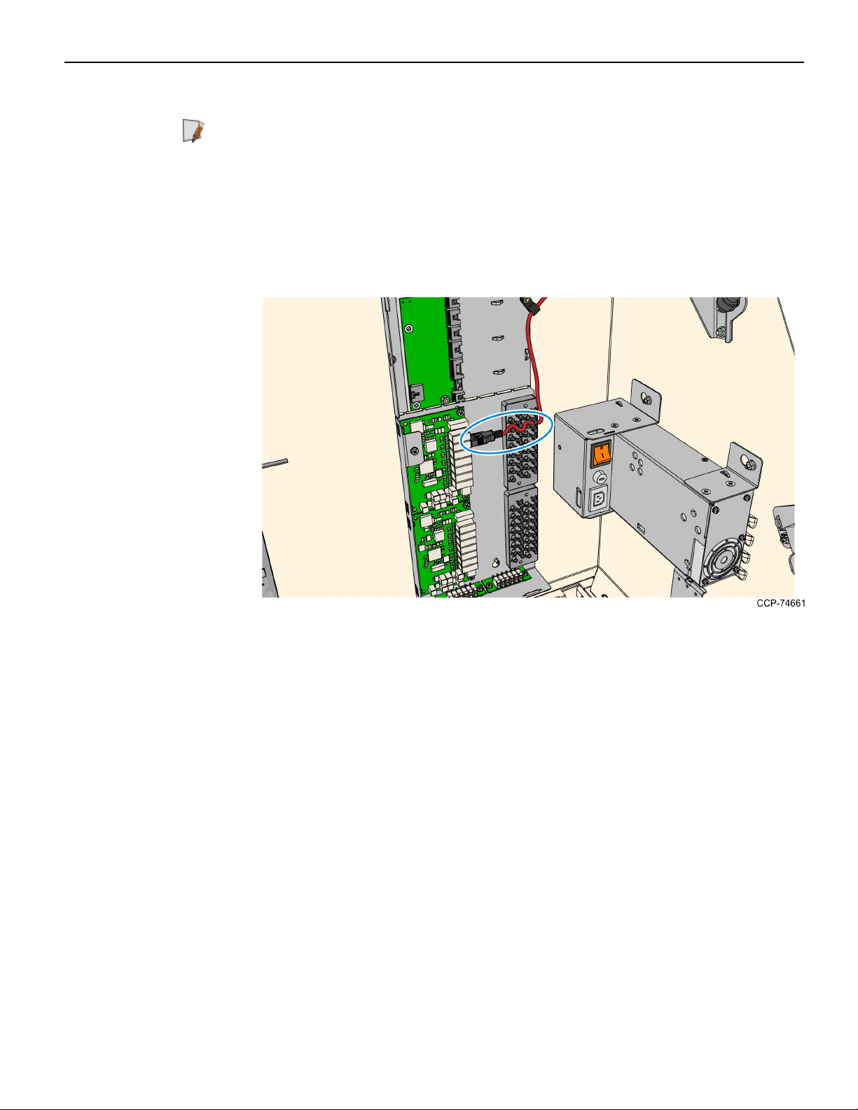
3. In the Top Box, place the 12V DCRegulator assembly and connect the DC cable to
the regulator.
Note: If the kiosk previously contained a Sankyo MSR or a UX300 MSR in the Kiosk
Front Panel, then the 12VDCRegulator may already be present in the kiosk.
Note: For the next procedure, refer to Installation Procedure on page4.
Page 65

2-62 Verifone UX100, UX300, and UX400 Mount without Trackball
12VRegulator DCCable (009-0020734)
1. Connect one end of the DCcable to the 12V Regulator.
Note: If the kiosk previously contained a Sankyo MSRor UX300 MSR in the Kiosk
Front Panel, then this cable is already installed.
2. Mount and secure the 12VRegulator assembly to the kiosk.
a. Mount and partially tighten one M4 thread forming screw to the regulator
bracket on the Top Box.
Page 66

Verifone UX100, UX300, and UX400 Mount without Trackball 2-63
b. Insert the tab on the bottom side of the cover through the bottom slot on the
regulator bracket.
c. Insert the Keyhole Slot on the cover through the M4 screw on the regulator
bracket.
d. Tighten the screw to secure the 12VRegulator assembly.
3. Connect the other end of the DCDistribution harness to a free DCHub port in the
I/OPanel. Secure the cable with other DCcables as necessary.
Page 67

2-64 Verifone UX100, UX300, and UX400 Mount without Trackball
4. Tidy up and secure the cables near in the I/OPanel and Top Box as necessary as
shown below.
Note: For the next procedure, refer to Installation Procedure on page4.
Page 68

Verifone UX100, UX300, and UX400 Mount without Trackball 2-65
Securing the USB, Power, and Antenna Cables
1. Bundle the UX400 Antenna and Comms cables together and secure the bundle to the
fascia frames using cable ties.
2. Double–check if all cables are neatly bundled and secure by cable ties or cable
clamps. Pay close attention to cables that are connected to the UX100 PINPad and
the UX300 MSR.
Note: For sample cabling and tie downs of UX cables, see the images on the
following page.
Caution: Ensure that the Antenna and Comms cables do not interfere when
opening or closing the upper enclosure fascia.
Note: For the next procedure, refer to Installation Procedure on page4.
Page 69

2-66 Verifone UX100, UX300, and UX400 Mount without Trackball
Page 70

Verifone UX100, UX300, and UX400 Mount without Trackball 2-67
Page 71

2-68 Verifone UX100, UX300, and UX400 Mount without Trackball
Installing the I/O Panel Cover
1. At the bottom part of the I/O Panel, align the tabs on the cover to the slot of the
I/OPanel.
2. At the top part, of the I/O assembly, align the slots of the cover to the tabs on the
I/OPanel.
3. Carefully slide the cover downwards inserting the tabs to the slots and mounting
screw through the cover keyhole slot. Make sure that the cables are not pinched or
snagged by the cover.
4. Tighten the screw to secure the cover to the panel.
Note: For the next procedure, refer to Installation Procedure on page4.
Page 72

Verifone UX100, UX300, and UX400 Mount without Trackball 2-69
Validating Installation of Verifone UX Devices
To validate installation of Verifone devices, follow the procedures depending on your
specific implementation.
Page 73

2-70 Verifone UX100, UX300, and UX400 Mount without Trackball
Interconnection Diagram
The illustration below shows the UX100 PINPad, UX300 MSR, and UX400 NFCReader
connection diagram to the NCRSelfServ 75 (7705) Kiosk.
 Loading...