

Page 1

NCR S26 Hot Plug Server
User Guide
Release 3
BST0-2140-4700
12/97
Page 2

The product described in this book is a licensed product of NCR Corporation.
Brand and product names appearing in this manual are for identification purposes only and
may be registered trademarks or trademarks of their respective companies.
It is the policy of NCR Corporation (NCR) to improve products as new technology,
components, software, and firmware become available. NCR, therefore, reserves the right to
change specifications without prior notice.
All features, functions, and operations described herein may not be marketed by NCR in all
parts of the world. In some instances, photographs are of equipment prototypes. Therefore,
before using this document, consult with your NCR representative or NCR office for
information that is applicable and current.
To maintain the quality of our publications, we need your comments on the accuracy, clarity,
organization, and value of this book.
Address correspondence to:
Systems Information
NCR Corporation
3325 Platt Springs Road
West Columbia, SC 29170
Copyright © 1997
By NCR Corporation
Dayton, Ohio U.S.A.
All Rights Reserved
Page 3

Contents
Preface
About This Book............................................................................................................ i
Who Should Read This Book......................................................................................... i
Conventions Used in This Book....................................................................................ii
Related Publications...................................................................................................... ii
Chapter 1
Installation and Documentation Overview
Where to Start .................................................................................................................. 1-2
Documentation and Additional Help................................................................................. 1-3
Documentation .......................................................................................................... 1-3
Additional Help ......................................................................................................... 1-4
Compliance and Regulatory Statements............................................................................ 1-5
Declaration of the Manufacturer or Importer.............................................................. 1-5
Safety Compliance..................................................................................................... 1-5
Electromagnetic Compatibility (EMC)....................................................................... 1-5
Electromagnetic Compatibility Notice (USA)............................................................. 1-6
FCC Declaration of Conformity................................................................................. 1-7
Electromagnetic Compatibility Notices (International)............................................... 1-8
Chapter 2
Using System Features
ESD Precautions............................................................................................................... 2-2
Identifying System Features.............................................................................................. 2-3
Identifying the Rear Panel Features................................................................................... 2-5
Positioning the System...................................................................................................... 2-6
Opening the System.......................................................................................................... 2-8
Configuring the System Board........................................................................................ 2-10
Features................................................................................................................... 2-10
Major Components .................................................................................................. 2-10
Jumper Settings ....................................................................................................... 2-12
NCR S26 Hot Plug Server User Guide iii
Page 4

Contents
Connector Functions.................................................................................................2-13
Chapter 3
Adding and Replacing Components
ESD Precautions................................................................................................................3-2
Installing CPU Boards.......................................................................................................3-3
Types of CPU Boards..................................................................................................3-3
Installation .................................................................................................................3-3
Warnings....................................................................................................................3-3
Upgrading the Memory......................................................................................................3-5
Configurations............................................................................................................3-5
Restrictions.................................................................................................................3-6
Installing and Removing SIMMs.......................................................................................3-7
Installing SIMMs........................................................................................................3-8
Removing SIMMs.......................................................................................................3-9
Reconfiguring the System.........................................................................................3-10
Upgrading the Video Memory .........................................................................................3-11
Expanding the PCI System..............................................................................................3-12
Installing PCI Devices.....................................................................................................3-13
Using the SCSI Feature ...................................................................................................3-14
Installing and Removing Expansion Boards.....................................................................3-15
Identifying Expansion Boards...................................................................................3-15
Installing an Expansion Board ..................................................................................3-16
Removing an Expansion Board.................................................................................3-17
Installing Drives..............................................................................................................3-18
Removing the Upper Front Panel Cover and Frame ..................................................3-18
Installing a 3.5-inch Peripheral Drive.......................................................................3-19
Installing a 5.25-inch Peripheral Drive.....................................................................3-21
Removing a 5.25-inch Peripheral Drive.................................................................... 3-23
Installing a Hot Plug Fixed Disk Drive .....................................................................3-23
Chapter 4
Using the BIOS Setup Utility
When to Use the BIOS Setup Utility..................................................................................4-2
Run Setup Message Repeatedly Received....................................................................4-2
Before Running Setup.................................................................................................4-2
Entering Setup...................................................................................................................4-3
Basic System Configuration...............................................................................................4-4
Date and Time............................................................................................................4-5
Diskette Drives...........................................................................................................4-6
IDE Hard Disk Drives.................................................................................................4-7
System Memory..........................................................................................................4-8
iv Contents
Page 5

Contents
Communication Settings............................................................................................ 4-8
Enhanced IDE Features ............................................................................................. 4-9
On Board IDE............................................................................................................ 4-9
Large Memory Support Mode .................................................................................. 4-10
Num Lock After Boot............................................................................................... 4-10
Memory Test............................................................................................................ 4-10
Auto Configuration Mode........................................................................................ 4-10
Fast Boot Mode........................................................................................................ 4-11
Advanced System Configuration..................................................................................... 4-12
Shadow RAM .......................................................................................................... 4-13
Internal Cache (CPU Cache).................................................................................... 4-13
External Cache ........................................................................................................ 4-13
ECC/Parity Mode Selection...................................................................................... 4-13
Memory at 15 MB - 16 MB...................................................................................... 4-14
PCI System Configuration .............................................................................................. 4-15
PCI IRQ Setting....................................................................................................... 4-15
VGA Palette Snoop.................................................................................................. 4-16
Onboard SCSI.......................................................................................................... 4-17
Non-PnP ISA Card Configuration................................................................................... 4-18
IRQ/DMA................................................................................................................ 4-19
Expansion ROM Region.......................................................................................... 4-19
I/O Region............................................................................................................... 4-20
Power Saving Configuration........................................................................................... 4-21
Power Management Mode........................................................................................ 4-21
System Wake Up Events .......................................................................................... 4-22
System Security .............................................................................................................. 4-23
Disk Drive Control .................................................................................................. 4-23
Onboard Communication Ports................................................................................ 4-24
Onboard PS/2 Mouse (IRQ 12) ................................................................................ 4-27
Setup Password........................................................................................................ 4-27
Power On Password ................................................................................................. 4-28
Remote Diagnostic Configuration ............................................................................ 4-28
Load Setup Default Settings............................................................................................ 4-29
Leaving Setup................................................................................................................. 4-30
Hard Disk Drive Types ................................................................................................... 4-31
Chapter 5
Using the System Utilities
Identifying the System Utilities......................................................................................... 5-2
Using the AFlash BIOS Utility.......................................................................................... 5-3
Executing AFlash ...................................................................................................... 5-3
Quick Way to Execute AFlash.................................................................................... 5-4
NCR S26 Hot Plug Server User Guide v
Page 6

Contents
Using the EISA Configuration Utility................................................................................5-5
Functions....................................................................................................................5-5
Making Menu Selections ............................................................................................5-5
Getting Help...............................................................................................................5-7
Accessing the ECU.....................................................................................................5-7
Configuring Your Computer Initially........................................................................5-10
Adding or Removing Boards.....................................................................................5-14
Viewing or Editing Configuration Details.................................................................5-16
Appendix A
420-Watt Power Supply Requirements
Input Requirements..........................................................................................................A-2
Output Requirements........................................................................................................A-3
Appendix B
Error Messages
Types of Error Messages...................................................................................................B-2
Software Error Messages..................................................................................................B-3
System Error Messages.....................................................................................................B-4
Correcting Error Conditions.............................................................................................B-6
Appendix C
Sample Configurations
Types of Sample Configurations.......................................................................................C-2
Sample Standard Configuration........................................................................................C-3
Installing the Hardware .............................................................................................C-3
Configuring the System Settings................................................................................C-4
Configuring the PCI Adapters....................................................................................C-7
Configuring the SCSI Adapters and Drives................................................................C-8
If the ECU Will Not Boot ........................................................................................C-10
Configuring Memory and Other Baseboard Settings ................................................C-10
Sample RAID Configuration ..........................................................................................C-13
Installing the Hardware ...........................................................................................C-13
Configuring the System Settings..............................................................................C-14
Configuring the PCI Adapters..................................................................................C-17
Configuring the SCSI Adapters and Drives.............................................................. C-18
Configuring the Memory and Other Baseboard Settings...........................................C-20
Configuring the Mylex RAID Array Group..............................................................C-22
Appendix D
Hot Plug Backplane
Features............................................................................................................................D-2
vi Contents
Page 7

Contents
Major Components ...........................................................................................................D-3
Hot Plug Backplane ...................................................................................................D-4
Hot Plug SCSI Drive Tray..........................................................................................D-5
SCSI Channel Configurations...........................................................................................D-6
Single-Channel Configuration ...................................................................................D-7
Dual-Channel Configuration......................................................................................D-9
Setting Hard Disk ID Options.........................................................................................D-11
Strapping the SCSI IDs on the Backplane................................................................D-11
Strapping the SCSI IDs on the Drive........................................................................D-13
Installation .....................................................................................................................D-14
Using the System Board SCSI Connectors................................................................D-14
Using an Add-on SCSI Controller Board .................................................................D-18
Using the Hot Plug Feature.............................................................................................D-20
Appendix E
System Support Log
Introduction................................................................................................................... ...E-2
System Identification........................................................................................................E-3
NCR Hardware Support Services ......................................................................................E-4
NCR On-Site Hardware Support Services...................................................................E-4
NCR Technical Support Web Site..............................................................................E-4
NCR Support Phone Numbers...........................................................................................E-5
Before Placing a Hardware Support Call....................................................................E-5
Placing a Hardware Support Call...............................................................................E-5
Placing a Software Support Call.................................................................................E-6
List of NCR Support Telephone Numbers ..................................................................E-7
Other Areas Support..................................................................................................E-9
Customer Support Agreement.........................................................................................E-11
Overview........................................................................................................................E-12
Support Services.............................................................................................................E-13
System Numbers......................................................................................................E-13
NCR On-Site Hardware Support Services.................................................................E-14
NCR Support Phone Numbers..................................................................................E-14
Placing a Hardware Support Call.............................................................................E-15
Placing a Software Support Call...............................................................................E-16
Hardware Records...........................................................................................................E-17
Different Types of Logs............................................................................................E-17
Software Records............................................................................................................E-27
Current System Configuration ........................................................................................E-41
Adapter Board Locations .........................................................................................E-41
System Equipment List............................................................................................E-41
Hardware Configuration Report...............................................................................E-41
NCR S26 Hot Plug Server User Guide vii
Page 8

Contents
Preventive Maintenance..................................................................................................E-46
General Customer Preventive Maintenance Guidelines............................................E-46
General Customer Preventive Maintenance Procedures............................................E-47
Installation Records........................................................................................................E-53
Customer Support Agreement......................................................................................... E-54
List of NCR Support Telephone Numbers....................................................................... E-55
NCR Faxback System .............................................................................................. E-55
United States Support .............................................................................................. E-55
Other Areas Support................................................................................................ E-56
viii Contents
Page 9

About This Book
This book provides information about the installation, set up, configuration,
and operation of the server.
Its goal is to familiarize you with the system and to provide a reference to
answer your future questions.
Who Should Read This Book
This book should be used by persons experienced in configuring and installing
server hardware.
Preface
NCR S26 Hot Plug Server User Guide i
Page 10

Preface
Conventions Used in This Book
The following are various conventions used in this book:
F1
Enter
X + Y
Keyboard
Detected
Note
CAUTION
WARNING
A letter, number, symbol, or word in this font represents a key on
your keyboard. For example, the instruction “press F1” means
press the key labeled “F1” on your keyboard.
This represents the key labeled “Enter” on your keyboard.
Two or three key names, separated by plus signs, indicate
multiple-key entries. For example,
down
This is the font used to denote screen messages.
Notes indicate pivotal information and may be used to
emphasize a recommended sequence of steps.
Cautions indicate hazards that might cause personal injury,
damage to hardware, or software if the hazards are not avoided.
Warnings indicate hazards that can cause personal injury or
equipment damage if the hazards are not avoided.
Related Publications
For supplementary information, refer to the following books:
NCR S26 Hot Plug Server Installing Network Operating System
NCR S26 Hot Plug Server Quick Hardware Installation
Ctrl
and
Alt
and press
Ctrl + Alt + Del
Del
.
means hold
BST0-2140-48
BST0-2140-49
Other publications may later become available. Check with your NCR sales
representative for the latest information.
ii Preface
Page 11

Chapter 1
Installation and Documentation
Overview
NCR S26 Hot Plug Server User Guide 1-1
Page 12

Where to Start
Where to Start
To install and configure your server, perform these steps.
Step What to Do How to Do It Where to Find Information
1 Install any hardware
you want to add
2 Configure system
settings
3 Configure the PCI
adapters
4 Configure the SCSI
adapters and drives
5 Configure memory
and other system
board settings
Install appropriate
disk drives,
peripherals, and
adapters
Use the BIOS
Setup Utility
Use the BIOS
Setup Utility
Use the Adaptec
SCSI adapter
firmware Setup
Utility
Use the EISA
Configuration
Utility
Quick Hardware Installation
brochure
Chapters 2 and 3 of
User
Guide
Drive, peripheral, CPU
board, and adapter
documentation
Quick Hardware Installation
brochure
Chapter 2 of
Installing
Network Operating System
Chapter 4 of
Same as Step 2
Adaptec SCSI Adapter
documentation
Chapter 4 of
User Guide
Installing
Network Operating System
Quick Hardware Installation
brochure
Chapter 3 of
Installing
Network Operating System
6 Configure EISA
adapters
1-2 Installation and Documentation Overview
Use the ESIA
Configuration
Utility
Chapters 3 and 5 of
User
Guide
Quick Hardware Installation
brochure
Chapter 3 of
Installing
Network Operating System
Chapter 5 of
User Guide
Page 13

Documentation and Additional Help
Documentation and Additional Help
This section describes the documentation packaged with your server and how
to find additional help.
Documentation
The following documents are provided to help you install, upgrade, maintain,
and troubleshoot your server. Keep all documentation together in a safe place.
• Quick Hardware Installation (BST0-2140-49)
This brochure provides you with information to install your server
quickly.
• User Guide (BST0-2140-47)
This is the manual you are now reading. It provides you with more
detailed server information.
• Installing Network Operating System (BST0-2140-48)
This manual describes the procedures for installing an operating system.
You should also refer to the documentation that comes with your
operating system.
• Drive, peripheral, CPU board, and adapter documentation
If you have ordered optional features, such as drives, peripheral devices,
CPU boards, or adapters, documentation for those items is packed with
the server. This documentation is important to configure your server
properly.
CAUTION: Do not discard any of this documentation. You may need it
again if your server ever requires service or you change the configuration.
Keep it in a safe place with the other server documentation.
NCR S26 Hot Plug Server User Guide 1-3
Page 14

Documentation and Additional Help
Additional Help
If you need additional help, refer to Appendix E, “System Support Log,” of
this manual. Appendix E contains a list of NCR support telephone numbers
and instructions on maintaining support data.
1-4 Installation and Documentation Overview
Page 15

Compliance and Regulatory Statements
Compliance and Regulatory Statements
Declaration of the Manufacturer or Importer
We hereby certify that this product is in compliance with European Union
EMC Directive 89/336/EEC, using standards EN55022 (Class A) and
EN50082-1 and Low Voltage Directive 73/23/EEC, Standard EN60950.
Safety Compliance
USA: UL listed to1950, 3rd Edition
Canada: UL certified to CSA C22.2 No. 950-95 for Canada
Europe: TUV/GS certified to EN60950 2nd Edition, with amendments
International: GOST-R certified for Russia
Electromagnetic Compatibility (EMC)
USA: FCC 47 Class A CFR Parts 2 and 15, Tested Class A
Canada: IC ICES-003 Class A
Europe: EN55022, Class A
EN50082-1
EN61000-4-2 ESD Susceptibility
EN61000-4-3 Radiated Immunity
EN61000-4-4 Electrical Fast Transient
International: CISPR 22/93, Class A
Australia VAS/N253548, C-Tick Mark
Taiwan EMC Certification CNS13438
Japan: VCCI Class A ITE
NCR S26 Hot Plug Server User Guide 1-5
Page 16

Compliance and Regulatory Statements
Electromagnetic Compatibility Notice (USA)
This equipment has been tested and found to comply with the limits for a
Class A digital device, pursuant to Part 15 of the FCC Rules. These limits are
designed to provide reasonable protection against harmful interference in a
residential installation. This equipment generates, uses, and can radiate radio
frequency energy and, if not installed and used in accordance with the
instructions, may cause harmful interference to radio communications.
However, there is no guarantee that interference will not occur in a particular
installation. If this equipment does cause harmful interference to radio or
television reception, which can be determined by turning the equipment off and
on; the user is encouraged to try to correct the interference by one or more of
the following measures:
• Reorient or relocate the receiving antenna.
• Increase the separation between the equipment and the receiver.
• Connect the equipment into an outlet on a circuit different from that to
which the receiver is connected.
• Consult the dealer or an experienced radio/TV technician for help.
Any changes or modifications not expressly approved by the grantee of this
device could void the user’s authority to operate the equipment. The customer
is responsible for ensuring compliance of the modified product.
Only peripherals (computer input/output devices, terminals, printers, etc.) that
comply with FCC Class A limits may be attached to this computer product.
Operation with noncompliant peripherals is likely to result in interference to
radio and TV reception.
All cables used to connect to peripherals must be shielded and grounded.
Operation with cables, connected to peripherals, that are not shielded and
grounded may result in interference to radio and TV reception.
Note: A Class A device installed within a residential area is likely to cause
harmful interference.
1-6 Installation and Documentation Overview
Page 17

FCC Declaration of Conformity
Product Type: COLRED
This device complies with Part 15 of the FCC Rules. Operation is subject to
the following two conditions: (1) This device may not cause harmful
interference, and (2) this device must accept any interference received,
including interference that may cause undesired operation.
This equipment has been tested and found to comply with the limits for a
Class A digital device, pursuant to Part 15 of the FCC Rules. These limits are
designed to provide reasonable protection against harmful interference in a
residential installation. This equipment generates, uses, and can radiate radio
frequency energy and, if not installed and used in accordance with the
instructions, may cause harmful interference to radio communications.
However, there is no guarantee that interference will not occur in a particular
installation. If this equipment does cause harmful interference to radio or
television reception, which can be determined by turning the equipment off and
on, the user is encouraged to try to correct the interference by one or more of
the following measures:
Compliance and Regulatory Statements
• Reorient or relocate the receiving antenna
• Increase the separation between the equipment and receiver
• Connect the equipment into an outlet on a circuit different from that to
which the receiver is connected
• Consult the dealer or an experienced radio/TV technician for help.
NCR S26 Hot Plug Server User Guide 1-7
Page 18

Compliance and Regulatory Statements
Electromagnetic Compatibility Notices (International)
When used near a radio or TV receiver, it may become the cause of radio
interference.
Read the instructions for correct handling.
This equipment has been tested for radio frequency emissions and has been
verified to meet CISPR 22 Class A.
Cet appareil numérique respecte les limites bruits radioélectriques applicables
aux appareils numériques de Classe A prescrites dans la norme sur le matériel
brouilleur: “Appareils Numériques”, NMB-003 édictée par le Ministre
Canadian des Communications.
This digital apparatus does not exceed the Class A limits for radio noise
emissions from digital apparatus set out in the interference-causing equipment
standard entitled “Digital Apparatus”, ICES-003 of the Canadian Department
of Communications.
1-8 Installation and Documentation Overview
Page 19

Chapter 2
Using System Features
NCR S26 Hot Plug Server User Guide 2-1
Page 20

ESD Precautions
ESD Precautions
To avoid damaging electronic equipment from electrostatic discharge (ESD),
always observe the following precautions before installing any system
component:
1. Do not remove a board from its packaging until you are ready to install it.
Integrated circuits (ICs) on expansion boards are highly sensitive to static
electricity.
2. Wear a wrist grounding strap before handling electronic components.
Wrist grounding straps are available at most electronic component stores.
2-2 Using System Features
Page 21
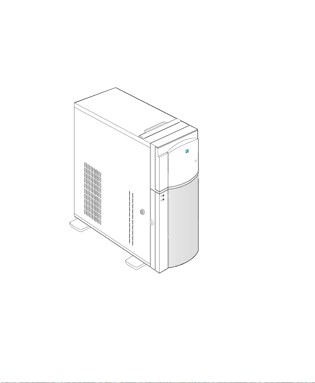
Identifying System Features
This section describes major system features.
Figure 2-1. Front View
Identifying System Features
The system has the following minimum features:
• System board
• 420-watt power supply
• Seven I/O expansion slots (2 EISA, 4 PCI and 1 shared)
• Fast and Wide SCSI-2 controller integrated on the system board
• Video port
NCR S26 Hot Plug Server User Guide 2-3
Page 22

Identifying System Features
• Two 9-pin serial ports
• 25-pin parallel port
• Keyboard and mouse ports
• One 3.5-inch 1.44 MB flex drive
• System cabinet
• Eight 3.5-inch hot plug bays and three 5.25-inch user accessible bays,
plus a bay for the 3.5-inch flex drive
• Remote Diagnostic Management (RDM) Module
2-4 Using System Features
Page 23

Identifying the Rear Panel Features
Identifying the Rear Panel Features
The figure below illustrates the rear panel features.
Figure 2-2. Rear Panel Features
Power supply
COM 1
COM 2
Keyboard port
Mouse port
Video port
Parallel port
Expansion slots
PCI 1
PCI 2
PCI 3
PCI 4
PCI 5/EISA 1
EISA 2
EISA 3
External SCSI
NCR S26 Hot Plug Server User Guide 2-5
Page 24
Positioning the System
Positioning the System
When positioning the system, arrange the legs of the housing so that the
weight of the system is evenly distributed and is stable.
Figure 2-3. Arranging the System in a Stable Position (Bottom View)
2-6 Using System Features
Page 25

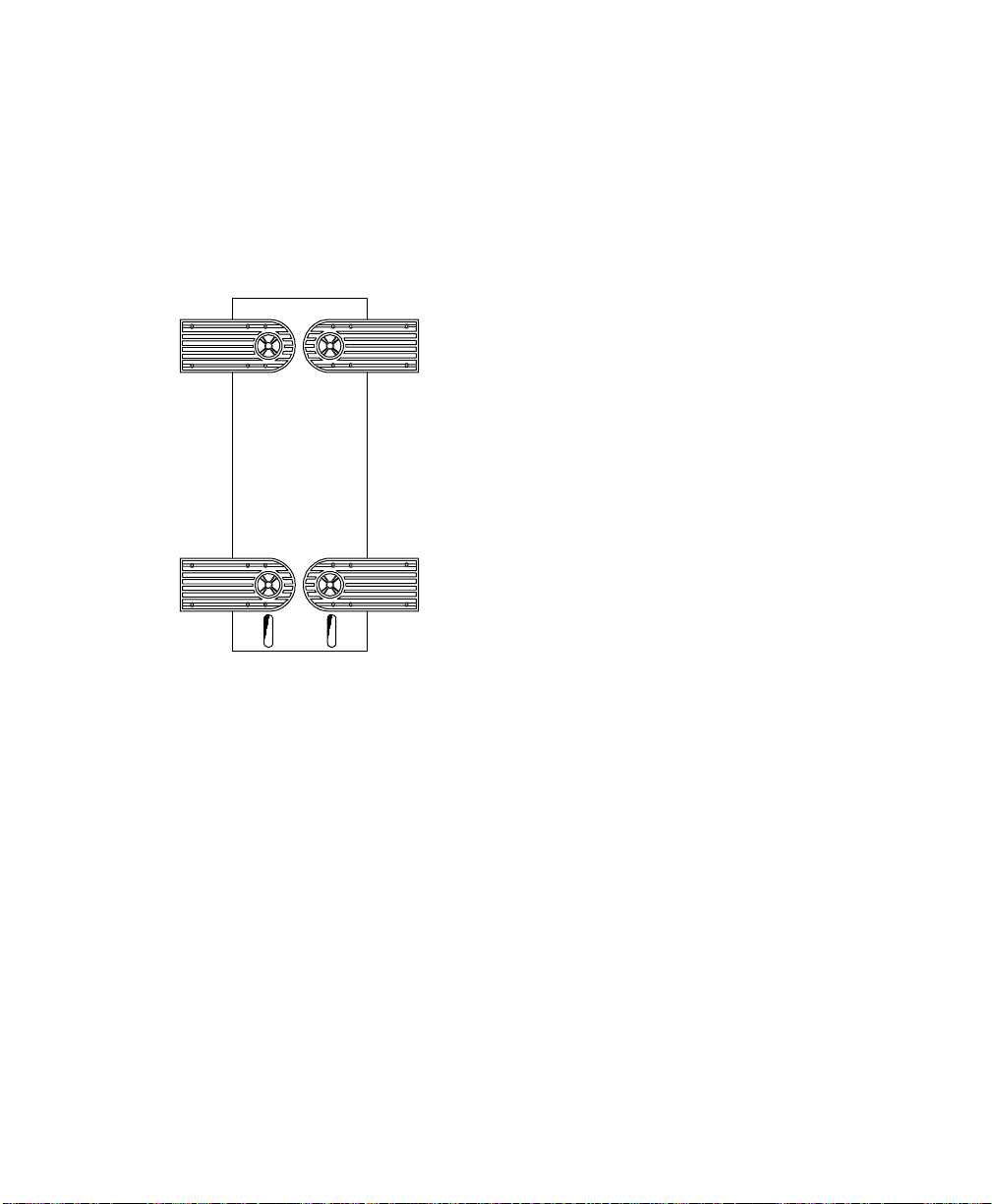
Positioning the System
When standing the system with the fan against a wall, leave a space of
5-10 cm from the wall to allow air circulation, then position the legs as in
“Position A” below.
When standing the system with the fan facing out, you can put the system
close to the wall and position the legs as in “Position B” below.
Figure 2-4. Allowing for Air Circulation (Bottom View)
Fan Fan
NCR S26 Hot Plug Server User Guide 2-7
Page 26
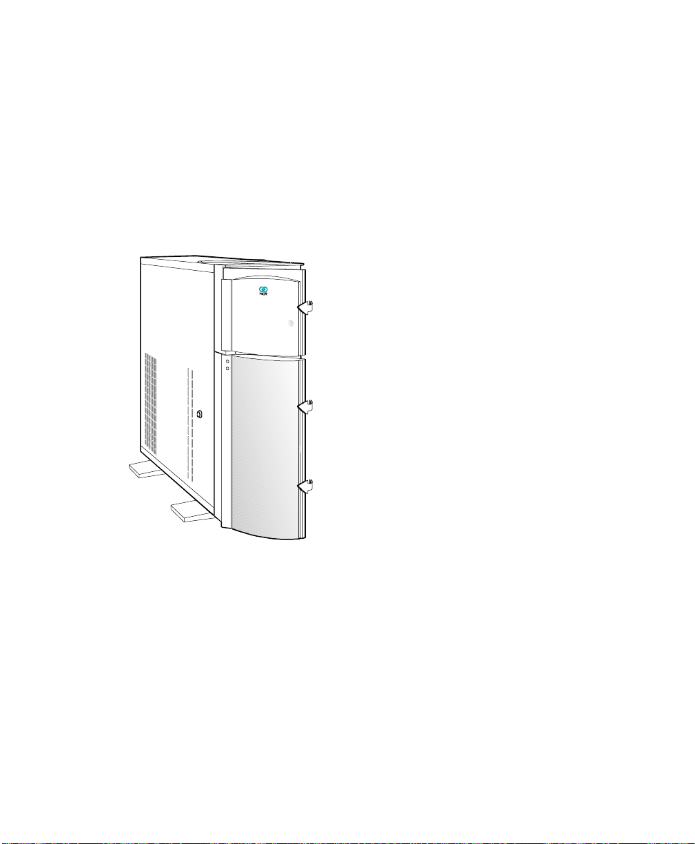
Opening the System
Opening the System
CAUTION: Read the “ESD Precautions” section earlier in this chapter
before proceeding.
The figure below illustrates how to open the system. The keys to the housing
are inside the upper front panel.
Figure 2-5. Opening the System
2-8 Using System Features
Page 27

Opening the System
To open the system, follow these steps:
1. Open the top front cover by pressing the indentation.
2. Open the lower front panel by pulling on the right side, at the indentation.
3. Unlock the housing, using the key.
Figure 2-6. Opening the Cabinet Housing
Note: You can not remove the key after you have unlocked the housing. You
can remove it only when you lock the housing again.
4. Pull on the key to swing the left side of the housing open. If necessary,
you may use a screwdriver gently to pry the side of the housing open.
NCR S26 Hot Plug Server User Guide 2-9
Page 28

Configuring the System Board
Configuring the System Board
This section contains information to help you properly configure the system
board.
Features
The 64-bit, high-performance system board supports both the Intel Pentium
and Pentium Pro™ microprocessors (also called CPUs). However, to provide
maximum upgradability and flexibility, the microprocessors are not installed
on the system board.
Instead, the system board has a special slot designed to accommodate a
separate CPU board. This dual-processor CPU board contains both
microprocessors and the embedded 512 KB pipeline burst second-level cache.
See the section, “Installing CPU Boards,” in Chapter 3 of this manual.
Standard features such as a video port, two serial ports, one parallel port,
diskette drive interface, and embedded fixed disk drive interface reside on the
system board.
The system board has a 0 MB base memory and supports a maximum
memory of 512 MB using 64 MB single-density single inline memory modules
(SIMMs). A functional system is recommended to have at least 16 MB of
RAM.
Major Components
The system board has the following major components:
™
• Eight 72-pin SIMM sockets labeled Bank 0, 1, 2, and 3 (two sockets
comprise one bank) that support single- and double-density 60/70 ns
SIMMs
• One CPU board slot
• Two 32-bit EISA expansion slots supporting master/slave add-on cards
• Four PCI local bus slots
2-10 Using System Features
Page 29

Configuring the System Board
• One shared slot (EISA or PCI)
• 256 KB flash ROM for easy system BIOS upgrade
• System clock/calendar plus 8 KB extended CMOS RAM with battery
backup
• Onboard AIC-7880 chip that supports one SCSI-2 port
• 50-pin Fast SCSI-2 and 68-pin Wide SCSI interfaces
• Remote Diagnostic Management (RDM) module
• I/O interfaces for one video slot, two serial ports, one parallel port,
peripheral drives, IDE drives, and one PS/2 keyboard and mouse
• Power connector for 420-watt switching power supply
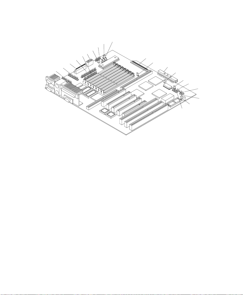
The figure below shows the location of the major components on the system
board.
Figure 2-7. System Board Layout
Fan connector 1 (FA1)
Fan connector 2 (FA2)
Fan connector 3 (FA3)
RDM Module
Video RAM
Wide SCSI connector
Narrow SCSI connector
COM1
COM2
Mouse port
Keyboard port
Parallel port
Video port
Video upgrade sockets
CPU board slot
Buzzer
Flash ROM BIOS
Real-time clock
PCI slots
EISA slots
NCR S26 Hot Plug Server User Guide 2-11
Page 30
Configuring the System Board
Figure 2-8. System Board Jumper Locations
CN8
CN5
CN2
CN7
CN6
CN1
SW1
CN3
JP1
JP2
CN11
JP3
CN12
JP4
JP5
CN14
CN15
CN16
JP6
CN13
Jumper Settings
You have to change the jumper settings on the system board when you
upgrade the CPU or reconfigure the system.
To change a jumper setting, follow these steps:
1. Remove the jumper cap from the jumper.
2. Position the jumper cap over the two pins for the desired setting.
3. Gently press the cap over the pins.
2-12 Using System Features
Page 31

Configuring the System Board
The table below lists the system board jumpers and their corresponding
settings. The asterisks indicate the default settings. See Figure 2-8 for jumper
locations.
Table 2-1. Jumper Settings
Jumper Setting Function
JP1 1-2
2-3*
JP2 2-3 Standard System BIOS
JP3 1-2
2-3*
JP4 1-2*
2-3
JP5 1-2
2-3*
JP6 1-2*
2-3
Connector Functions
The table below lists the different connectors on the system board and their
respective functions.
Table 2-2. Connector Functions
Connector Function
CN1 Power connector
CN2 Power connector
CN3 Backplane board HDD status connector
CN5 IDE hard disk connector
CN6 RDM connector
CN7 RDM connector
CN8 Diskette drive connector
Check Password
Bypass Password
Terminator always set to ON
Use SCSI Setup Utility to set terminator to ON or OFF
Wide SCSI
Standard
Hardware Reset Enabled
Hardware Reset Disabled
Audio to Buzzer
Audio to Speaker
NCR S26 Hot Plug Server User Guide 2-13
Page 32

Configuring the System Board
Connector Function
CN11 68-pin Wide SCSI connector
CN12 50-pin Fast SCSI-2 connector
CN13 Power LED connector and RDM switch cable from front of unit
CN14 Hard disk LED connector
CN15 No connection
CN16 Speaker connector
SW1 NMI switch
2-14 Using System Features
Page 33

Chapter 3
Adding and Replacing
Components
NCR S26 Hot Plug Server User Guide 3-1
Page 34

ESD Precautions
ESD Precautions
To avoid damaging electronic equipment from electrostatic discharge (ESD),
always observe the following precautions before installing any system
component:
1. Do not remove a board from its packaging until you are ready to install it.
Integrated circuits (ICs) on expansion boards are highly sensitive to static
electricity.
2. Wear a wrist grounding strap before handling electronic components.
Wrist grounding straps are available at most electronic component stores.
3-2 Adding and Replacing Components
Page 35

Installing CPU Boards
This section provides information on CPU boards for your server.
Types of CPU Boards
The system board has one CPU board slot that supports these two types of
CPU boards:
• CPU board that supports the Intel Pentium™ processor
• CPU board that supports the Intel Pentium Pro™ processor
Installation
If you ordered a CPU board factory-installed, you may skip this chapter. If
you must install a CPU board in your system, read all of this information.
When actually performing the installation, refer to the following documents
for information on installing CPU boards in the system:
Installing CPU Boards
• Quick Hardware Installation that came with your system
• Release Notes that came with your CPU board
• Figure 2-7 in Chapter 2 of this manual for the location of the CPU board
slot on the system board
Warnings
When installing CPU boards, do not attempt to make any hardware changes
unless you are a qualified technician. Ask your dealer for assistance.
There are two released versions of system BIOS. One is for the CPU board
that supports the Pentium processor. The other is for the CPU board that
supports the Pentium Pro processor. These versions of BIOS are not
interchangeable. Flashing the incorrect version renders the system unusable.
NCR S26 Hot Plug Server User Guide 3-3
Page 36

Installing CPU Boards
For example, if you flash the BIOS version released for a Pentium CPU board
on a system configured with a Pentium Pro CPU board you cannot use the
system. If this happens, you must insert the appropriate CPU board into the
system and reflash the original BIOS.
Refer to the diskette label to make sure you are using the appropriate BIOS
for your system configuration.
3-4 Adding and Replacing Components
Page 37

Upgrading the Memory
You can upgrade the system memory by adding single inline memory modules
(SIMMs) into the SIMM sockets or by changing the SIMMs for a higher
memory configuration.
Configurations
The table below lists the available memory configurations.
Table 3-1. Memory Configurations
Upgrading the Memory
Bank
0
S1 S2 S3 S4 S5 S6 S7 S8 Memory
8 MB 8 MB 16 MB
16
MB
32
MB
8 MB 8 MB 16 MB 16 MB 48 MB
8 MB 8 MB 32 MB 32 MB 80 MB
16
MB
8 MB 8 MB 16 MB 16 MB 48 MB
8 MB 8 MB 16 MB 16 MB 16
8 MB 8 MB 16 MB 16 MB 32
16
MB
32
MB
16
MB
Bank
1
32 MB 32 MB 96 MB
Bank
2
8 MB 8 MB 8 MB 8 MB 32 MB
16
MB
32
MB
MB
MB
16
MB
32
MB
16
MB
32
MB
Bank
3
16
MB
32
MB
16
MB
32
MB
Total
32 MB
64 MB
64 MB
128 MB
80 MB
112 MB
NCR S26 Hot Plug Server User Guide 3-5
Page 38

Upgrading the Memory
Bank
0
S1 S2 S3 S4 S5 S6 S7 S8 Memory
8 MB 8 MB 16 MB 16 MB 32
8 MB 8 MB 8 MB 8 MB 16
8 MB 8 MB 8 MB 8 MB 32
16
MB
8 MB 8 MB 8 MB 8 MB 8 MB 8 MB 8 MB 8 MB 64 MB
16
MB
32
MB
64
MB
16
MB
16
MB
32
MB
64
MB
Bank
1
16 MB 16 MB 32
16 MB 16 MB 16
32 MB 32 MB 32
64 MB 64 MB 64
Bank
2
MB
MB
MB
MB
MB
MB
MB
32
MB
16
MB
32
MB
32
MB
16
MB
32
MB
64
MB
Bank
3
32
MB
16
MB
32
MB
32
MB
16
MB
32
MB
64
MB
32
MB
16
MB
32
MB
32
MB
16
MB
32
MB
64
MB
Total
176 MB
96 MB
160 MB
192 MB
128 MB
256 MB
512 MB
The configurations in Table 3-1 are only some of the available memory
combinations. You can use other combinations if you follow the rules for
upgrading memory as described below.
Restrictions
When adding memory, consider the following:
• Use only one type of SIMM in a given bank. You may combine different
types of SIMMs for a memory configuration only if the SIMMs in each
bank are the same type.
• You may use the memory banks (Bank0 ~ Bank3) in any order.
• Always install SIMMs in pairs. For example, for a total memory of
16 MB, install two 8 MB SIMMs in a bank. You cannot use a 16 MB
SIMM alone for 16 MB of memory.
3-6 Adding and Replacing Components
Page 39

Installing and Removing SIMMs
Installing and Removing SIMMs
CAUTION: Read the ESD precautions section earlier in this chapter before
proceeding.
Figure 3-1. SIMM Sockets
SIMM sockets
NCR S26 Hot Plug Server User Guide 3-7
Page 40

Installing and Removing SIMMs
Installing SIMMs
To install a SIMM, follow these steps:
1. Carefully slip a SIMM at a 45
curved edge that indicates pin 1 of the SIMM matches pin 1 of the socket.
Figure 3-2. Installing a SIMM
o
angle into a socket. Make sure that the
12
Pin 1 Indicator
(curved edge)
Hole
Peg
CAUTION: A SIMM fits only in one direction. If you slip in a SIMM but it
does not appear to completely fit, you may have inserted it the wrong way.
2. Gently push the SIMM to a vertical position until the pegs of the socket
slip into the holes on the SIMM. Make sure the holding clips lock the
SIMM into position.
o
Note: The SIMM should be at a 90
angle when installed on the system
board.
3-8 Adding and Replacing Components
Page 41

Removing SIMMs
To remove SIMMs, follow these steps:
1. Press the holding clips on both sides of the SIMM outward to release it.
2. Press the SIMM downward at about a 45o angle.
3. Pull the SIMM out of the socket.
Figure 3-3. Removing a SIMM
3
Installing and Removing SIMMs
Holding
clip
1
2
NCR S26 Hot Plug Server User Guide 3-9
Page 42

Installing and Removing SIMMs
Reconfiguring the System
Reconfigure the system after installing or removing SIMMs.
To reconfigure the system, follow these steps:
1. Reboot the system. A memory error message appears, indicating that the
total memory does not match the value stored in CMOS.
2. Press Ctrl + Alt + Esc to run Setup. A warning message appears,
indicating a wrong memory configuration.
3. Press Esc twice to exit Setup and reboot the system.
3-10 Adding and Replacing Components
Page 43

Upgrading the Video Memory
Increased video memory permits you to display higher resolution and more
colors. The system board has 1 MB of video memory factory-installed. You
may upgrade the video memory to 2 MB.
To upgrade the video memory, follow these steps:
1. Locate the video DRAM upgrade socket labeled U18 and U21 on the
system board. See the figure below.
Figure 3-4. Installing a Video Memory Chip
Pin 1
Indicator
Notched
Corner
Upgrading the Video Memory
2. Gently insert a video chip into each of the upgrade sockets. Make sure
that the pin 1 indicator on the chip matches the notched corner of the
socket.
NCR S26 Hot Plug Server User Guide 3-11
Page 44

Expanding the PCI System
Expanding the PCI System
The system board has a PCI-to-PCI bridge controller chipset that expands the
capability of the PCI system. This feature allows all five PCI slots in the
system to be bus masters.
The bridge has two interfaces. The primary interface connects directly to the
PCI bus close to the host CPU. The secondary interface creates a new PCI bus
that can operate independently from the primary PCI bus.
3-12 Adding and Replacing Components
Page 45

Installing PCI Devices
The devices you install in PCI slots 1 and 2 operate on the primary PCI bus.
The devices you install in PCI slots 3, 4, and 5 operate on the secondary PCI
bus.
Since the primary PCI bus operates faster than the secondary PCI bus, install
PCI add-on boards in PCI slots 1 and 2 first. Then use PCI slots 3, 4, and 5.
If you configure your PCI devices in this manner, the system will perform
better. See Figure 2-7 in Chapter 2 of this manual for the locations of the PCI
slots.
Installing PCI Devices
NCR S26 Hot Plug Server User Guide 3-13
Page 46

Using the SCSI Feature
Using the SCSI Feature
The system board features a single-chip Ultra Fast and Wide SCSI-2 host
adapter that adds SCSI I/O capability to the system.
The chipset consists of all the components found on the state-of-the-art SCSI
host adapters such as the following:
• Onboard microcontroller
• Bus master interface controller
• SCSI controller
The chipset allows transfers at a full 40 MB/second burst transfer rate.
Note: Ultra SCSI speed is not supported on external SCSI devices because of
the Ultra SCSI stringent requirements in total SCSI bus length. To use an
external SCSI devices, use the SCSISelect utility to disable support for Ultra
SCSI speed. See the heading, “Configuring the SCSI Adapters and Drives” in
the “Sample Standard Configuration” section of Appendix C.
To use the feature, install any SCSI device in your system and connect it to
the SCSI interface on the system board. (See Figure 2-7 in Chapter 2 of this
manual for the location.) Then, enter the BIOS Setup utility to set the PCI slot
parameters. See Chapter 4, “Using the BIOS Setup Utility”, for details in
setting the parameters. Refer to the SCSI manual for more information on
using SCSI.
3-14 Adding and Replacing Components
Page 47

Installing and Removing Expansion Boards
Installing and Removing Expansion Boards
This section describes in detail the steps needed to install expansion boards in
the system.
CAUTION: Read the “ESD Precautions” section earlier in this chapter
before proceeding.
Identifying Expansion Boards
There are three types of expansion boards:
• EISA
• ISA
• PCI
Each expansion board has a different type of connector, as illustrated below.
Figure 3-5. Expansion Board Connectors
ISA board EISA board PCI board
An ISA board has a single row of contacts along its connectors. There is
usually a single notch in the connector.
An EISA board has a double row of tightly spaced contacts along its
connector. There are usually six notches (five small ones and one large one) in
the connector.
NCR S26 Hot Plug Server User Guide 3-15
Page 48

Installing and Removing Expansion Boards
A PCI board has a single row of tightly spaced contacts along its connectors.
There is usually a single notch in the connector.
Installing an Expansion Board
To install an expansion board, follow these steps:
1. Study the documentation that came with your expansion board, and
configure any jumpers or switches on the board as directed.
2. Remove a bracket from any empty expansion slot. Save the screw to
secure the new board. Keep the bracket for future use. See the figure
below.
Figure 3-6. Removing a Bracket
3. Gently insert the board into an expansion slot. Make sure the board is
securely seated. See Figure 3-7.
4. Secure the board with the bracket screw.
3-16 Adding and Replacing Components
Page 49

Installing and Removing Expansion Boards
CAUTION: Do not neglect this step. The board uses the screw for
grounding.
Figure 3-7. Installing a Board
Removing an Expansion Board
To remove an expansion board, follow these steps:
1. Unplug any cables connected to the board.
2. Remove the bracket screw and pull the board out of the slot.
3. Secure a bracket cover to the empty slot with the screw.
NCR S26 Hot Plug Server User Guide 3-17
Page 50

Installing Drives
Installing Drives
CAUTION: Read the “ESD Precautions” section earlier in this chapter
before proceeding.
This section describes in detail how to install disk drives in the system.
Removing the Upper Front Panel Cover and Frame
When installing drives on the 5.25-inch drive bays, you have to remove the
upper front panel cover and frame. Follow these steps:
1. Open the lower front panel cover.
2. Press the latch under the upper front panel and pull as shown in the figure
below.
Figure 3-8. Removing the Upper Front Panel Cover and Frame
3-18 Adding and Replacing Components
Page 51

Installing a 3.5-inch Peripheral Drive
To install a 3.5-inch peripheral drive, follow these steps:
1. Remove the screw attaching the 3.5-inch drive frame to the housing.
2. Secure the drive on the drive frame.
Figure 3-9. Securing the Drive on the Frame
Installing Drives
3. Insert the drive into the third drive bay.
4. Secure it with a screw.
5. Connect the drive cables.
NCR S26 Hot Plug Server User Guide 3-19
Page 52

Installing Drives
Figure 3-10. Securing the Drive
3-20 Adding and Replacing Components
Page 53

Installing a 5.25-inch Peripheral Drive
To install a 5.25-inch peripheral drive, follow these steps:
1. Secure the drive guides on the sides of the peripheral drive as shown in the
figure below.
Figure 3-11. Securing the Drive Guides
Installing Drives
2. Insert the drive into a 5.25-inch drive bay.
3. Connect the drive cables.
NCR S26 Hot Plug Server User Guide 3-21
Page 54

Installing Drives
Figure 3-12. Inserting the Drive into the Drive Bay
3-22 Adding and Replacing Components
Page 55

Removing a 5.25-inch Peripheral Drive
To remove a 5.25-inch peripheral drive, follow these steps:
1. Disconnect all the drive cables.
2. Press the metal tabs on the sides of the drive and pull the drive out as
shown in the figure below.
Figure 3-13. Pulling the Drive Out
Installing Drives
Installing a Hot Plug Fixed Disk Drive
To install a hot plug fixed disk drive, refer to Appendix D in this manual. The
complete procedure is described there.
NCR S26 Hot Plug Server User Guide 3-23
Page 56

Installing Drives
3-24 Adding and Replacing Components
Page 57

Chapter 4
Using the BIOS Setup Utility
NCR S26 Hot Plug Server User Guide 4-1
Page 58

When to Use the BIOS Setup Utility
When to Use the BIOS Setup Utility
Most systems are already configured by the manufacturer or the dealer. There
is no need to run Setup when starting the computer unless you get a
configuration error.
Running Setup loads the configuration values into the battery-backed
nonvolatile memory called CMOS RAM. This memory area is not part of the
system RAM.
Run Setup Message Repeatedly Received
If you repeatedly receive a Run Setup message, the battery may be bad. In this
case, the system cannot retain the configuration values in CMOS. Ask a
qualified technician for assistance.
Before Running Setup
Before you run Setup, do the following:
• Know the type of diskette drive you have. The standard type is a 3.5-inch
1.44 MB diskette drive.
• Close all files and applications.
4-2 Using the BIOS Setup Utility
Page 59

Entering Setup
CAUTION: Close all open files and leave your application program before
entering Setup. You cannot exit back into an application. The system
automatically reboots when you leave Setup.
Press the key combination Ctrl + Alt + Esc during the power-on selftest (POST) to enter Setup. The BIOS Utility (Setup) main menu, as shown in
in the figure below appears.
Note: You can only enter Setup during POST. After POST, pressing
Ctrl + Alt + Esc has no effect.
Figure 4-1. BIOS Utility (Setup) Main Menu
Basic System Configuration
Advanced System Configuration
Non-PnP ISA Card Configuration
Power Saving Configuration
Remote Diagnostic Configuration
Load Setup Default Settings
Entering Setup
BIOS Utility
PCI System Configuration
System Security
= Move Highlight Bar, = Select, Esc = Exit and Reboot
NCR S26 Hot Plug Server User Guide 4-3
Page 60

Basic System Configuration
Basic System Configuration
Select Basic System Configuration to input configuration values such as date,
time, and disk types.
The figure below shows page 1 of the Basic System Configuration menu.
Figure 4-2. Basic System Configuration Menu, Page 1
xx
xx
Page 1/2
Sector
xx
xx
Basic System Configuration
.................
Date
.................
Time
Diskette DriveA
Diskette DriveB
Hard Disk 0 (xxx MB)
Hard Disk 1 (xxx MB)
Base Memory
Extended Memory
T otal Memory
Math Coprocessor
Video Display
= Move HighlightBar,
PgDn/PgUp = Move Screen, F1= Help, Esc= Exit
........
........
..........
..........
..........
[ MM/DD/YY ]
[ HH:MM:SS ]
[ xx-MB xx-inch ]
[ xx-MB xx-inch ]
....
[Auto]
....
[Auto]
[xxx]KB
......
[xxx]KB
[ xxxx ] KB
......
[ Installed ]
[ VGA/EGA ]
Cylinder
xx
xx
= Change setting,
Head
The command line at the bottom of the menu tells you how to highlight items,
change settings, and move from one screen to another.
• Press the up or down arrow key on the cursor-edit keypad to highlight the
desired parameter.
• Press the left or right arrow key to select the desired option for a
parameter.
• Press Page Down to move to the next page or Page Up to return to the
previous page.
• Press Esc to exit the configuration menu.
4-4 Using the BIOS Setup Utility
Page 61

Basic System Configuration
The figure below shows page 2 of the Basic System Configuration menu.
Figure 4-3. Basic System Configuration Menu, Page 2
Comm unication Settings
B aud Rate
Pa rity
Stop B its
Data L eng ths
Enhanced IDE Features
Hard Disk B l o ck Mod e
H ard Disk Size > 504MB
On Board IDE
Large Memory Support M ode
Num Lock After Boot
Memory Test
Auto Configuration Mode
Fast Boot Mode
= Move Highlight Bar,
PgDn/PgUp = Move Screen, F1 = H elp, E sc = Exit
The following sections explain the different parameters and their settings.
Date and Time
Basic System Configuration
. . . . . . . . . . . . . . . . .
. . . . . . . . . . . . . . . . . . . . .
. . . . . . . . . . . . . . . . . .
. . . . . . . . . . . . . .
. . . . . . .
. . . . .
. . . . . . . . . . . . . . . . . . .
. . . . . . .
. . . . . . . . . . . . .
. . . . . . . . . . . . . . . . . . . .
. . . . . . . . . .
. . . . . . . . . . . . . . . . .
Page 2/2
[ 9600 ] BPS
[ None ]
[ 1 ] B its
[ 8 ] B its
[ Disabled ]
[ Disabled ]
[ Disabled ]
[ Advanced ]
[ Enabled ]
[ Enabled ]
[ Disabled ]
[ Disabled ]
= Change setting,
The real-time clock keeps the system date and time. After setting the date and
time, you need not enter them every time you turn on the system. As long as
the internal battery remains good (approximately seven years) and connected,
the clock continues to keep the date and time accurately even when the power
is off.
NCR S26 Hot Plug Server User Guide 4-5
Page 62

Basic System Configuration
Date
Highlight the items on the Date parameter and press the left or right arrow key
to set the date following the month-day-year format.
Valid values for month, day, and year are as follows:
Month 1 to 12
Day 1 to 31
Year 00 to 99
The setting 00 for the Year represents year 2000.
Time
Highlight the items on the Time parameter and press the left or right arrow
key to set the time following the hour-minute-second format.
Valid values for hour, minute, and second are as follows:
Hour 00 to 23
Minute 00 to 59
Second 00 to 59
Diskette Drives
To enter the configuration value for the diskette drive(s), follow these steps:
1. Highlight the Diskette Drive A parameter.
2. Press the right or left arrow key to view the options and select the
appropriate value.
The Diskette Drive parameters have the following options:
– None
– 360 KB, 5.25-inch
– 1.2 MB, 5.25-inch
– 720 KB, 3.5-inch
4-6 Using the BIOS Setup Utility
Page 63

– 1.44 MB, 3.5-inch
– 2.88 MB, 3.5-inch
Follow the same procedure for the Diskette Drive B parameter. Choose None
if you do not have a second diskette drive.
IDE Hard Disk Drives
To enter the configuration value for the IDE hard disk drives, follow these
steps:
1. Move the highlight bar to the Hard Disk 0 parameter to configure the hard
disk drive (drive C).
2. Press the left or right arrow key to display the hard disk options with their
respective values.
3. Select the option that corresponds to your hard disk type.
Follow the same procedure for the Hard Disk 1 parameter. Choose None if
you do not have a second hard disk drive.
Basic System Configuration
Selecting the Auto Option
If you do not know the exact type of your IDE hard disk, select the option
Auto. During POST, when the system performs self-testing and selfinitialization before loading the operating system and applications, the BIOS
utility automatically determines the type of your hard disk. You can see the
hard disk values when you enter Setup.
Cylinder Head Sector
Hard Disk 0 (xxx MB) [Auto] xx xx xx
The next time you boot the system, Setup does not have to auto-configure
your hard disk because it reads the saved hard disk information during POST.
Note: We recommend that you copy the hard disk values and keep them in a
safe place in case you have to reconfigure the disk in the future.
Follow the same procedure to auto-configure other hard disks.
NCR S26 Hot Plug Server User Guide 4-7
Page 64

Basic System Configuration
Selecting the User Option
Choose the User option when you have installed a hard disk that was
previously formatted but does not use the disk native parameters or structure.
That is, the disk type may be in the hard disk types list but the number of
cylinders, heads, and sectors differ.
Cylinder Head Sector
Hard Disk 0 (xxx MB) [User] xx xx xx
To configure a hard disk with the User option, follow these steps:
1. Highlight the hard disk drive parameter.
2. Select the option User then press Enter.
3. Type in the number of cylinders, heads, and sectors of the hard disk drive,
under the appropriate columns.
Note: Be sure to have the correct hard disk information beforehand.
4. Choose YES when asked if you want to save the CMOS data.
System Memory
The system automatically detects the total amount of onboard memory during
the POST and sets the memory parameters accordingly. If you install
additional memory, the system automatically adjusts the Total Memory
parameter to display the new memory size.
Communication Settings
The Communication Settings parameters permit you to set the baud rate,
parity, stop bit and data length for the first serial port (COM 1). The values
for this parameter are:
Baud rate: 300 to 38400 bits per second (bps)
Parity: Odd, even, or none
Stop bit: 1 or 2 stop bits
Data length: 7- or 8-bit data word
4-8 Using the BIOS Setup Utility
Page 65

Note: The baud rate maximum value is only for the BIOS POST under
UNIX environment. The system I/O chipset SMC 37C665GT supports up to
115.2 Kbps.
Enhanced IDE Features
This section describes several enhanced IDE features.
Hard Disk Block Mode
The Hard Disk Block Mode function enhances disk performance depending on
the hard disk in use. If you set this parameter to Enabled, it permits data
transfer in block (multiple sectors) by increasing the data transfer rate to 256
bytes per cycle.
If your system does not boot after enabling this parameter, change the setting
to Disabled. This parameter is normally set to Disabled.
Hard Disk Size > 504 MB
This enhanced IDE feature works only under MS-DOS™ and Microsoft
Windows™ 3.x environments. If enabled, it permits you to use a hard disk
with a capacity of more than 504 MB. This is made possible through the
Logical Block Address (LBA) mode translation. Other operating systems
require this parameter to be set to Disabled.
Basic System Configuration
To prevent data loss, keep this parameter to Enabled if you are using a hard
disk with more than 504 MB capacity and was previously configured through
LBA mode. When you use a hard disk configured through the cylinder-headsector (CHS) mode, set this parameter to Disabled.
On Board IDE
This parameter permits the IDE to be disabled so that IRQ 14 can be used for
PCI or EISA adapters.
NCR S26 Hot Plug Server User Guide 4-9
Page 66

Basic System Configuration
Large Memory Support Mode
This parameter permits the system to support an extended memory higher than
64 MB. Set this parameter to Advanced if you are working under Microsoft
Windows NT™ environment and the system memory size is greater than or
equal to 64 MB. Otherwise, set it to Normal.
Num Lock After Boot
This parameter permits you to activate the Num Lock function upon booting.
The default setting is Enabled.
Memory Test
When set to Enabled, this parameter permits the system to perform a RAM
test during the POST routine. When set to Disabled, the system detects only
the memory size and bypasses the test routine. The default setting is Disabled.
This item is set to Disabled and is not user-configurable if you enabled the
Auto Configuration Mode and the Fast Boot Mode parameters on page 2 of
the Basic System Configuration menu. See the following headings, “Auto
Configuration Mode“ and “Fast Boot Mode.”
Auto Configuration Mode
When enabled, this parameter automatically sets the system configuration
values to their optimized settings. At the same time, it causes the Memory
Test parameter to be set to Disabled and the shadow RAM region for system
and video BIOS to be set to Enabled. For additional information, see the
headings, “Memory Test“ and “Shadow RAM.”
Set this parameter to Enabled if you do not know the hard disk drive type
parameters and the onboard communication port configuration.
4-10 Using the BIOS Setup Utility
Page 67

Fast Boot Mode
When enabled, this parameter permits the system to boot faster by skipping
some POST routines. It bypasses memory test, enables shadow RAM, and
enables primary- and second-level cache.
When set to Enabled, this parameter also causes the Memory Test parameter
to be set to Disabled and the shadow RAM regions for system and video BIOS
to Enabled. For additional information, see the headings, “Memory Test“ and
“Shadow RAM.”
Basic System Configuration
NCR S26 Hot Plug Server User Guide 4-11
Page 68

Advanced System Configuration
Advanced System Configuration
The Advanced System Configuration option permits you to configure the
advanced system memory functions.
CAUTION: Do not attempt to change any setting in the Advanced System
Configuration if you are not a qualified technician.
The figure below shows page one of the Advanced System Configuration
parameters.
Figure 4-4. Advanced System Configuration, Page One
Advanced System Configuration
ShadowRAM
E0000h - FFFFFh
C0000h - C7FFFh
C8000h - CBFFFh
CC000h - CFFFFh
D0000h - D3FFFh
D4000h - D7FFFh
D8000h - DBFFFh
DC000h - DFFFFh
Internal Cache (CPU Cache)
External Cache
ECC/Parity Mode Selection
Operation of ECC
Memory at 15MB-16MB Researved for
=MoveHighlightBar,
PgDn/PgUp = Move Screen, F1 = Help, Esc = Exit
.......................
(System BIOS)
(VideoBIOS)
................
................
................
................
................
................
.............
..............
.................
....
.....
.....
= Change setting,
[ Enabled ]
[ Enabled ]
[ Disabled ]
[ Disabled ]
[ Disabled ]
[ Disabled ]
[ Disabled ]
[ Disabled ]
[ Enabled ]
[ Enabled ]
[ECC]
[ None ]
[System]Use
Page 1/1
4-12 Using the BIOS Setup Utility
Page 69

Shadow RAM
The system reserves 256 KB of random access memory (RAM) for the
shadow RAM function. This parameter has eight range addresses. When you
set these addresses to Enabled, the system BIOS, video BIOS, and I/O ROM
functions run directly from the shadow RAM for faster operation. When you
set them to Disabled, the functions run normally from ROM.
The address range E0000h - FFFFFh is for shadowing the system BIOS. This
item is always set to Enabled and is not user-configurable. The address range
C0000h - C7FFFh is for shadowing the video BIOS. Shadow RAM is set to
Enabled and is not user-configurable if the Auto Configuration Mode and the
Fast Boot Mode parameters on page 2 of the Basic System Configuration
menu are enabled. Otherwise, you can disable this item.
The remaining address ranges are for I/O ROM functions.
Internal Cache (CPU Cache)
This parameter enables or disables the internal cache memory. It is set to
Enabled and is not user-configurable if you enabled the Auto Configuration
Mode and Fast Boot Mode parameters on page 2 of the Basic System
Configuration menu. Otherwise, you can disable this item.
Advanced System Configuration
External Cache
This parameter enables or disables the external cache memory. It is set to
Enabled and is not user-configurable if you enabled the Auto Configuration
Mode and Fast Boot Mode parameters on page 2 of the Basic System
Configuration menu. Otherwise, you can disable this item.
ECC/Parity Mode Selection
This parameter permits you to enable or disable the ECC and parity check
feature. Fast-page mode SIMMs supports both ECC and parity mode while
EDO SIMMs supports only ECC mode.
NCR S26 Hot Plug Server User Guide 4-13
Page 70

Advanced System Configuration
You must disable this parameter if you installed SIMMs without parity.
Operation of ECC
This parameter permits you to select the error detection mode. The ECC
operation options follow:
• None - detects single-bit errors and automatically corrects any error but
does not set the single-bit error flag in the chipset. In this option, the
operating system does not receive any signal even if there are system
errors.
• Single-bit - detects single-bit errors, automatically corrects any error, and
sets the single-bit error flag in the chipset. The setting of the single-bit
error flag is a signal to the operating system that ECC detected single-bit
errors.
• Multiple-bit - detects multiple-bit errors and sets the multiple-bit error
flag in the chipset but does not correct the errors. The setting of the
multiple-bit error flag is a signal to the operating system that ECC
detected multiple-bit errors.
• Both - detects both single- and multiple-bit errors but corrects only single-
bit errors. This option sets both the single-and multiple-bit flags in the
chipset to send signals to the operating system that ECC detected errors.
Memory at 15 MB - 16 MB
To prevent memory address conflicts between the system and expansion
boards, reserve this memory range for the use of either the system or an
expansion board. Before setting this parameter, check your add-on expansion
board manual to determine if the board needs this memory space. If not, set
this parameter to System Use.
4-14 Using the BIOS Setup Utility
Page 71

PCI System Configuration
The PCI System Configuration, as shown in the figure below, permits you to
specify the settings for your PCI devices.
Figure 4-5. PCI System Configuration
PCI System Configuration
PCI IRQ Setting
PCI Slot 1
PCI Slot 2
PCI Slot 3
PCI Slot 4
PCI Slot 5
Onboard VGA
Onboard SCSI
VGA Palette Snoop
On Board SCSI
Boot Device
= Move HighlightBar,
PgDn/PgUp = Move Screen, F1 = Help, Esc = Exit
PCI IRQ Setting
This parameter allows for Auto or Manual configuration of PCI devices. If
you use plug-and-play (PnP) devices, you can keep the default setting Auto.
The system then automatically configures the PnP devices. If your PCI device
is not a PnP, you can manually assign the interrupt for each device. Refer to
your adapter board documentation for technical information.
PCI System Configuration
...........
...........
...........
...........
...........
...........
........
.......
........
............
.........
[Auto]
INTA
[--]
[--]
[--]
[--]
[--]
[--]
[--]
[ Disabled ]
[ Enabled ]
[ Disabled ]
= Change setting,
INTB
[--]
[--]
[--]
[--]
[--]
INTC
[--]
[--]
[--]
[--]
[--]
Page 1/1
INTD
[--]
[--]
[--]
[--]
[--]
Note: When the PCI IRQ Setting is set to Auto, all the IRQ setting fields
become gray and non-configurable.
NCR S26 Hot Plug Server User Guide 4-15
Page 72

PCI System Configuration
PCI Slots
These parameters permit you to specify the appropriate interrupt for each of
the PCI devices. You can assign IRQ5, IRQ9, IRQ10, IRQ11, or IRQ15 to
the slots. If you disabled the parallel, serial, and IDE ports, you may also use
IRQ3, IRQ4, IRQ7, or IRQ14 for the PCI slots.
Note: To avoid conflicts, make sure that the interrupts you assign in any of
the PCI slots are not used by other devices.
Press the up and down arrows to move between fields. Press left and right
arrows to select options.
Onboard VGA
This parameter permits you to manually assign the interrupt for the onboard
VGA when the PCI IRQ Setting parameter is set to Manual. This parameter is
grayed and not configurable when the PCI IRQ Setting is set to Auto.
Press the up and down arrows to move between fields. Press left and right
arrows to select options.
Onboard SCSI
This parameter permits you to manually assign the interrupt for the onboard
SCSI hard disk when the PCI IRQ Setting parameter is set to Manual. This
parameter is grayed and not configurable when the PCI IRQ Setting is set to
Auto.
Press the up and down arrows to move between fields. Press left and right
arrows to select options.
VGA Palette Snoop
PCI devices support the palette snooping technique that enables the device to
control access to their palette registers. Set this parameter to Enabled to
activate the palette snooping function if both the PCI VGA and the ISA video
devices are installed. Check your VGA board documentation for more
information about this function.
4-16 Using the BIOS Setup Utility
Page 73

Onboard SCSI
This parameter permits you to enable or disable the onboard SCSI feature.
Boot Device
This parameter permits you to enable or disable the onboard SCSI boot
priority.
PCI System Configuration
NCR S26 Hot Plug Server User Guide 4-17
Page 74

Non-PnP ISA Card Configuration
Non-PnP ISA Card Configuration
The Non-PnP (plug-and-play) ISA Card Configuration parameters permit you
to specify the settings for ISA boards (called cards by this utility) without the
plug-and-play (PnP) feature.
Figure 4-6. Non-PnP ISA Card Configuration, Page One
DMA 0
DMA 1
DMA 2
DMA 3
DMA 4
DMA 5
DMA 6
DMA 7
Page 1/2
..[No]
..[No]
..[--- ]*
..[No]
..[--- ]*
..[No]
..[No]
..[No]
..[No]
..[No]
..[No]
Non-PnP ISA Card Configuration
SystemResources Used by Non-PnP ISA Cards
IRQ/DMA
Expansion ROM Region
= Move HighlightBar ,
PgDn/PgUp = Move Screen, F1 = Help, Esc = Exit
. . [ --- ] *
IRQ00
. . [ --- ] *
IRQ01
. . [ --- ] *
IRQ02
..[No]
IRQ03
..[No]
IRQ04
..[No]
IRQ05
. . [ --- ] *
IRQ06
..[No]
IRQ07
C8000h- CBFFFh
CC000h - CFFFFh
D0000h - D3FFFh
..[No]
..[No]
..[No]
IRQ08
IRQ09
IRQ10
IRQ11
IRQ12
IRQ13
IRQ14
IRQ15
..[--- ]*
..[No]
..[No]
..[No]
..[No]
..[--- ]*
..[--- ]*
..[No]
D4000h - D7FFFh
D8000h- DBFFFh
DC000h - DFFFFh
= Change setting,
Note: The items marked No are currently not in use, while those marked Yes
are in use by PnP boards. The grayed items (here denoted with asterisks) have
fixed settings and are not user-configurable.
Refer to your non-PnP ISA board documentation when setting the parameters
shown in Figure 4-7.
4-18 Using the BIOS Setup Utility
Page 75

Non-PnP ISA Card Configuration
Figure 4-7. Non-PnP ISA Card Configuration, Page Two
I/O Region
PgDn/PgUp= Move Screen, F1 = Help, Esc = Exit
IRQ/DMA
These items permit you to assign specific IRQ and DMA channels to non-PnP
ISA boards. The system will not use such IRQ and DMA channels when it
automatically assigns channels to PnP boards.
Non-PnP ISA Card Configuration
100h - 10Fh
110h- 11Fh
120h - 12Fh
130h - 13Fh
140h - 14Fh
150h - 15Fh
160h - 16Fh
170h - 17Fh
180h - 18Fh
190h - 19Fh
1A0h - 1AFh
1B0h - 1BFh
1C0h - 1CFh
1D0h - 1DFh
1E0h - 1EFh
1F0h - 1FFh
= Move Highlight Bar,
..[No]
..[No]
..[No]
..[No]
..[No]
..[No]
..[No]
..[No]
..[No]
..[No]
..[No]
..[No]
..[No]
..[No]
..[No]
..[--- ]*
200h - 20Fh
210h - 21Fh
220h - 22Fh
230h - 23Fh
240h - 24Fh
250h - 25Fh
260h - 26Fh
270h - 27Fh
280h - 28Fh
290h - 29Fh
2A0h - 2AFh
2B0h - 2BFh
2C0h - 2CFh
2D0h - 2DFh
2E0h - 2EFh
2F0h - 2FFh
= Change setting,
..[No]
..[No]
..[No]
..[No]
..[No]
..[No]
..[No]
..[No]
..[No]
..[No]
..[No]
..[No]
..[No]
..[No]
..[No]
..[No]
300h - 30Fh
310h - 31Fh
320h - 32Fh
330h - 33Fh
340h - 34Fh
350h - 35Fh
360h - 36Fh
370h - 37Fh
380h - 38Fh
390h - 39Fh
3A0h - 3AFh
3B0h - 3BFh
3C0h - 3CFh
3D0h - 3DFh
3E0h - 3EFh
3F0h - 3FFh
Page 2/2
..[No]
..[No]
..[No]
..[No]
..[No]
..[No]
..[No]
..[No]
..[No]
..[No]
..[No]
..[No]
..[No]
..[No]
..[No]
..[No]
Expansion ROM Region
These items specify the memory regions available for add-on board use. You
can manually assign specific regions to non-PnP boards so that the system will
not use those regions when it automatically configures PnP boards.
NCR S26 Hot Plug Server User Guide 4-19
Page 76

Non-PnP ISA Card Configuration
I/O Region
The items under this parameter permit you to reserve 16-byte memory address
ranges for non-PnP boards. When the system configures PnP boards, the
address ranges that you marked will not be used.
You can assign random memory addresses to non-PnP boards as long as you
cover the address range required by the board. For example, for a board that
requires 178h-188h address, you have to set regions 170h-17Fh and 180h18Fh to Yes.
4-20 Using the BIOS Setup Utility
Page 77

Power Saving Configuration
The Power Saving Configuration parameters permit you to configure the
system power management feature.
The figure below shows the Power Saving Configuration parameters and their
default settings.
Figure 4-8. Power Saving Configuration
Power Saving Configuration
Power Saving Configuration
Power Management Mode
IDE Hard Disk Standby Timer
System Suspend Timer
System Wake Up Events
= Move Highlight Bar,
PgDn/PgUp = Move Screen, F1 = Help, Esc = Exit
IRQ 0
IRQ 1
IRQ 3
IRQ 4
IRQ 5
IRQ 6
IRQ 7
....
[ Disabled ] *
....
[ Enabled ] *
....
[ Disabled ]
....
[ Disabled ]
....
[ Disabled ]
....
[ Enabled ] *
....
[ Disabled ]
...........
Note: The grayed items (here denoted with asterisks) have fixed settings and
are not user-configurable.
Power Management Mode
This parameter permits you to reduce power consumption. When it is set to
Enabled, you can configure the monitor power-saving timer, IDE hard disk
standby timer, and the system suspend timer. The following sections describe
the timers.
....
.........
IRQ 8
IRQ 9
IRQ 10
IRQ 11
IRQ 12
IRQ 13
IRQ 14
IRQ 15
= Change setting,
[ Disabled ]
[OFF]
[OFF]
[ Disabled ]
....
[ Disabled ]
....
[ Disabled ]
...
[ Disabled ]
...
[ Enabled ] *
...
[ Disabled ]
...
[ Enabled ] *
...
[ Disabled ]
...
Page 1/1
NCR S26 Hot Plug Server User Guide 4-21
Page 78

Power Saving Configuration
IDE Hard Disk Standby Timer
This parameter permits the hard disk to enter standby mode after inactivity of
1 to 15 minutes, depending on your setting. When you access the hard disk
again, allow 3 to 5 seconds (depending on the hard disk used) for the disk to
return to normal speed. Set this parameter to Off if your hard disk does not
support this function.
System Suspend Timer
This parameter supports the lowest power saving mode. To resume system
operation from suspend mode, you can either press a key or move the mouse.
Any IRQ activity representing green/wake up events also resumes system
operation. See the following heading, “System Wake Up Events.”
Note: If you connected the system to a network, we strongly suggest you set
this item to OFF.
System Wake Up Events
This parameter permits you to monitor system activities occurring through the
IRQ and determine whether or not to enter power saving mode.
For example, if you assign IRQ3 to a fax/modem, and you set this item to
Enabled, any fax/modem activity wakes up the system from suspend mode.
4-22 Using the BIOS Setup Utility
Page 79

System Security
The Setup program has a number of security features to prevent unauthorized
access to the system and its data.
Enter the Setup program and select System Security. The following screen
appears.
Figure 4-9. System Security
System Security
Disk Drive Control
Diskette Drive
Hard Disk Drive
System BootDrive
Onboard Communication Ports
Serial Port 1
Serial Port 2
Parallel Port
Onboard PS/2Mouse (IRQ12)
SetupPassword
Power-on Password
= Move Hig hlight Bar,
PgDn/PgUp = Move Screen, F1 = Help, Esc = Exit
...............
...............
...............
Operation Mode
ECP DMAChannel
................
Disk Drive Control
The disk drive control features permit you to enable or disable the read/write
functions of a disk drive. These features can also control the diskette drive or
hard disk drive boot function. They prevent loading operating systems or other
programs from a certain drive while the other drives remain operational.
System Security
.............
............
..........
.......
....
.....
.............
Page 1/1
[Normal]
[Normal]
[DriveAthenC]
[3F8h]
[2F8h]
[378h(IRQ7)]
[ Standard ParallelPort (SPP)] Mode
[-]
[ Enabled ]
[None]
[None]
= Change setting,
NCR S26 Hot Plug Server User Guide 4-23
Page 80

System Security
The table below lists the drive control settings and their corresponding
functions.
Table 4-1. Drive Control Settings
Diskette Drive
Setting Description
Normal Diskette drive functions normally
Write Protect All Sectors Disables the write function on all sectors
Write Protect Boot Sector Disables the write function only on boot sector
Disabled Disables all diskette functions
Hard Disk Drive
Setting Description
Normal Hard disk drive functions normally
Write Protect All Sectors Disables the write function on all sectors
Write Protect Boot Sector Disables the write function only on boot sector
Disabled Disables all hard disk functions
System Boot Drive
Setting Description
Drive A then C System boots from drive A to C
Drive C then A System boots from drive C to A
C: System always boots from drive C
A: System always boots from drive A
Onboard Communication Ports
This section describes the onboard communication ports.
4-24 Using the BIOS Setup Utility
Page 81

System Security
Serial Port 1 Base Address
This parameter permits you to set serial port 1 logical base address.
Table 4-2. Serial Port 1 Settings
Setting Description
3F8h (default) Serial port 1 with address 3F8h using IRQ4
2F8h Serial port 1 with address 2F8h using IRQ3
3E8h Serial port 1 with address 3E8h using IRQ4
2E8h Serial port 1 with address 2E8h using IRQ3
Disabled Disables serial port 1
Serial Port 2 Base Address
This parameter permits you to set serial port 2 logical base address.
Table 4-3. Serial Port 2 Settings
Setting Description
3F8h Serial port 2 with address 3F8h using IRQ4
2F8h (default) Serial port 2 with address 2F8h using IRQ3
3E8h Serial port 2 with address 3E8h using IRQ4
2E8h Serial port 2 with address 2E8h using IRQ3
Disabled Disables serial port 2
Note: If you assign 3F8h to serial port 1, you can only assign 2F8h or 2E8h
to serial port 2. If you assign 2F8h to serial port 1, you can only assign 3F8h
or 3E8h to serial port 2.
Parallel Port Base Address
The system has one parallel port. The table below lists the options for
selecting the parallel port address. You also have the option to disable the
parallel port.
NCR S26 Hot Plug Server User Guide 4-25
Page 82

System Security
Table 4-4. Parallel Port Settings
Setting Function
3BCh (IRQ 7) Corresponds to the parallel port with address 3BCh
378h (IRQ 7) Corresponds to the parallel port with address 378h
278h (IRQ 5) Corresponds to the parallel port with address 278h
Disabled Disables the parallel port
To deactivate the parallel port, select the Disabled option. If you install an
add-on card with a parallel port whose address conflicts with the onboard
parallel port, the system automatically disables the onboard functions.
Check the parallel port address on the add-on card and change the address to
one that does not conflict.
Operation Mode permits you to set the operation mode of the parallel port.
The table below lists the available operation modes of the parallel port.
Table 4-5. Parallel Port Operation Mode Settings
Setting Function
Standard Parallel Port (SPP) Allows normal speed one-way operation
Standard and Bidirectional Allows normal speed operation in a two-way
Enhanced Parallel Port (EPP) Allows bidirectional parallel port operation at
Extended Capabilities Port (ECP) Allows parallel port to operate in
ECP DMA Channel becomes active only if you selected Extended
Capabilities Port (ECP) as the operation mode. It permits you to select DMA
channel 1 or DMA channel 3 (as required in Microsoft Windows95™).
4-26 Using the BIOS Setup Utility
mode
maximum speed
bidirectional mode and at a speed higher
than the maximum data transfer rate
Page 83

Onboard PS/2 Mouse (IRQ 12)
This parameter enables or disables the onboard PS/2 mouse. When set to
Enabled, it permits you to use the onboard PS/2 mouse assigned with IRQ12.
When set to Disabled, it deactivates the mouse and frees IRQ12 for the use of
other devices.
Setup Password
The Setup password prevents unauthorized access to the BIOS Utility.
Note: Set jumper JP1 on the system board to pins 1-2 to enable the password
function.
Setting a Password
1. Highlight the Setup Password parameter and press the left- or right-arrow
key. The password prompt appears.
2. Type a password. The password may consist of up to seven characters.
System Security
CAUTION: Be careful when typing your password because the
characters do not appear on the screen.
3. Press Enter. A screen message asks you to retype the password to verify
your first entry.
4. Retype the password then press Enter.
After setting the password, the system automatically sets the Setup Password
parameter to Present. The next time you want to enter the BIOS utility, you
must type your Setup password.
If You Forget the Password
If you forget your password, you must reset the configuration values stored in
CMOS to their default values. Should this happen, call your dealer for
assistance.
NCR S26 Hot Plug Server User Guide 4-27
Page 84

System Security
Power On Password
The power-on password secures your system against unauthorized use. Once
you set this password, you have to type it whenever you boot the system. To
set this password, follow the same procedure as setting a Setup password.
Remote Diagnostic Configuration
The remote diagnostic configuration allows the RDM notification procedure to
be set. This is described fully in the NCR ValuePlus CD for BackOffice,
Release 4.2, User’s Guide that is included with the system.
4-28 Using the BIOS Setup Utility
Page 85

Load Setup Default Settings
Use this option to load the default settings for the optimized system
configuration.
When you load the default settings, some of the parameters are grayed-out
with their fixed settings. These grayed parameters are not user-configurable.
To change the settings of these “non user-configurable” items, disable the
Auto Configuration Mode and the Fast Boot Mode parameters under the Basic
System Configuration menu.
Load Setup Default Settings
NCR S26 Hot Plug Server User Guide 4-29
Page 86

Leaving Setup
Leaving Setup
Examine the system configuration values. When you are satisfied that all the
values are correct, write them down. Store the recorded values in a safe place.
In the future, if the battery loses power or the CMOS chip is damaged, you
know what values to enter when you rerun Setup.
To leave Setup, follow these steps:
1. Press Esc to leave Setup.
2. If there is any change in the BIOS utility functions, the following message
appears:
Do you want to save CMOS data?
[Yes] [No]
Select your response with the arrow keys. Select Yes to store the new data
in the CMOS. Select No to retain the old configuration values.
3. Press Enter.
4-30 Using the BIOS Setup Utility
Page 87

Hard Disk Drive Types
The table below lists the hard disk drive types and parameters.
Table 4-6. Hard Disk Drive Types
Type Cylinders Heads Sectors Per Track
0 (indicates SCSI or no hard disk)
1 306 4 17
2 615 4 17
3 615 6 17
4 940 8 17
5 940 6 17
6 615 4 17
7 462 8 17
8 733 5 17
9 900 15 17
10 820 3 17
11 855 5 17
12 855 7 17
13 306 8 17
14 733 7 17
15 (reserved)
16 612 4 17
17 977 5 17
18 977 7 17
19 1024 7 17
20 733 5 17
21 733 7 17
22 733 5 17
Hard Disk Drive Types
NCR S26 Hot Plug Server User Guide 4-31
Page 88

Hard Disk Drive Types
Type Cylinders Heads Sectors Per Track
23 306 4 17
24 612 4 17
25 306 4 17
26 612 4 17
27 698 7 17
28 976 5 17
29 306 4 17
30 611 4 17
31 732 7 17
32 1023 5 17
33 751 8 17
34 755 16 17
35 731 13 26
36 980 15 17
37 936 16 17
38 981 5 17
39 981 10 17
40 762 8 39
41 980 5 17
42 832 8 33
43 683 12 38
44 513 16 38
45 776 8 33
46 683 16 38
47 832 6 33
48 615 2 34
49 989 16 63
50 823 4 38
4-32 Using the BIOS Setup Utility
Page 89

Hard Disk Drive Types
Type Cylinders Heads Sectors Per Track
51 1001 15 17
52 1024 17 22
53 723 13 51
54 548 8 38
55 1013 4 41
56 929 15 17
57 817 14 36
58 723 13 81
59 802 4 39
60 1024 9 17
61 895 5 55
62 (reserved)
63 966 10 34
64 1024 8 17
65 1024 11 17
66 918 11 17
67 905 9 17
68 1024 10 17
69 1024 12 17
70 1024 13 17
71 1024 14 17
72 1024 2 17
73 1024 16 17
74 918 15 17
75 820 6 17
76 1024 5 17
77 1024 8 17
78 (reserved)
NCR S26 Hot Plug Server User Guide 4-33
Page 90

Hard Disk Drive Types
Type Cylinders Heads Sectors Per Track
79 1001 15 32
80 1024 16 63
81 1024 10 17
82 1024 11 17
83 1024 15 17
84 776 8 33
85 926 13 17
86 805 4 26
87 976 5 17
88 745 4 28
89 747 2 28
90 782 2 1Bh
91 985 13 32
92 816 15 32
93 968 5 17
94 903 8 46
95 966 5 34
96 535 10 50
97 715 10 50
98~100 (reserved)
Auto or User (User-defined)
4-34 Using the BIOS Setup Utility
Page 91

Chapter 5
Using the System Utilities
NCR S26 Hot Plug Server User Guide 5-1
Page 92

Identifying the System Utilities
Identifying the System Utilities
This chapter contains information about the system utilities that you use when
you upgrade your system.
These utilities are as follows:
• AFlash BIOS Utility
• EISA Configuration Utility (ECU)
Note: The AFlash BIOS Utility diskette does not come with the system
package. Ask your dealer or NCR sales representative for assistance if you
need the utility.
5-2 Using the System Utilities
Page 93

Using the AFlash BIOS Utility
This section contains information on using the AFlash BIOS utility.
CAUTION: Do not install memory-related drivers (XMS, EMS, DPMI)
when you use AFlash.
The AFlash functions support all the operations required for system Flash
ROM. The functions are as follows:
• Load BIOS file to buffer reads a specified file from a diskette to memory
for future program use or for check only. It supports the 64-KB, 128-KB,
192-KB, or 256-KB files.
• Save BIOS to disk file reads BIOS from the current BIOS area and
writes to the file specified by the user.
• Edit OEM string reads specified file from a diskette to memory, edits
OEM string and writes to a file.
• Program flash memory programs Flash memory according to the data
loaded in Load BIOS file to buffer. This function also shows the BIOS
checksum and BIOS type to make sure that the operation is correct.
Using the AFlash BIOS Utility
AFlash features password security to prevent unauthorized access.
Executing AFlash
To start AFlash, follow these steps:
1. Copy the MSG.DAT and AFLASH.EXE files from the system utilities
diskette into a subdirectory of your choice.
2. From that subdirectory, type AFLASH and press Enter.
3. A help message displays. Press any key to continue.
4. The main menu displays. Use the up- or down-arrow keys to highlight the
options. Press Enter to select.
5. If you want to save a copy of the current BIOS into a file, select Save
BIOS to Disk File.
NCR S26 Hot Plug Server User Guide 5-3
Page 94

Using the AFlash BIOS Utility
6. Select Load BIOS File to load the BIOS file into memory.
7. Select Program Flash Memory to erase the current BIOS, and program
Flash ROM.
WARNING: Never turn off the system power while Flash BIOS is
programming. This will destroy the BIOS.
8. Reboot the system.
Quick Way to Execute AFlash
When you have already copied the AFlash files into your hard disk, you can
type AFLASH [filename] and press Enter at the DOS prompt (subdirectory
where the files are located) to quickly execute the program.
The program automatically performs the loading and programming functions,
then reboots the system.
If the program cannot find the BIOS file, it returns to the main menu and
flashes the following message:
Can't Read This File !!!
Press any key to continue...
In this case, follow the previous procedure in the section, “Executing AFlash,”
for loading and programming the BIOS file using the main menu.
5-4 Using the System Utilities
Page 95

Using the EISA Configuration Utility
Using the EISA Configuration Utility
The EISA Configuration Utility (ECU) is a program that allows you to easily
configure your server. Use this utility for these tasks:
• To set up your server for the first time
• To change your configuration by adding or removing EISA or ISA boards
The program stores the configuration information in the nonvolatile memory
where it is available whenever you use your server.
Functions
The ECU does the following:
• Supports EISA and ISA boards, PCI devices, and plug-and-play ISA
boards
• Automatically detects EISA boards, PCI devices, and plug-and-play ISA
boards installed in the computer
• Helps you configure ISA board by providing the appropriate switch and
jumper settings
• Notifies you immediately if a conflict occurs during configuration
• Creates and maintains the System Configuration Information (SCI) file as
a backup for the computer’s nonvolatile memory
• Supports configuration (CFG) file extensions
• Allows you to set the computer’s date and time
Making Menu Selections
You can either use the keyboard or the mouse to make menu selections in the
EISA Configuration Utility program.
NCR S26 Hot Plug Server User Guide 5-5
Page 96

Using the EISA Configuration Utility
Using the Keyboard
To use the keyboard when making menu selections, refer to the table below.
Table 5-1. Keyboard Function Keys
Key Function
Tab
or down arrow
Shift + Tab
Up arrow or down arrow Moves the cursor between items within a list
Enter
Esc
Page Up, Page Down
or down arrow
Home
End
Ctrl + Home
Ctrl + End
or up arrow
, up arrow,
Moves the cursor to the next field
Moves the cursor to the previous field
Selects an item
Cancels the most recent action
Scrolls a screen
Moves the cursor to the top of a list
Moves the cursor to the bottom of a list
Moves the cursor to the beginning of a
menu
Moves the cursor to the end of a menu
Using the Mouse
To use the mouse when making menu selections, follow these steps:
1. Position the cursor over the desired option and press the left mouse button
to select it.
2. When a sub-menu displays, press the left button again to make a selection.
3. If a scroll bar displays on the right side of the screen, place the mouse
cursor over the arrow at the top or at the bottom of the scroll bar, then
press and hold the left mouse button to scroll up or down the page.
5-6 Using the System Utilities
Page 97

Getting Help
The EISA Configuration Utility (ECU) automatically displays information
about each choice on the main menu and the second-level menus. The utility
also allows you to access online help once you begin the configuration
process.
Press F1 to display the help menu. Press Esc to remove the help menu on the
screen.
Accessing the ECU
To use the basic ECU functions, follow these steps:
1. Insert the System Configuration diskette in drive A and turn on the
computer. (Reset the system if the power is already on.) The ECU Logo
screen displays.
2. Press any key to continue. A Welcome screen displays.
3. Press Enter to display the main menu, as shown in the figure below.
Using the EISA Configuration Utility
Figure 5-1. ECU Main Menu
Main Menu
Learn about configuring your computer
Configure computer
Set date
Set time
Maintain system configuration diskette
Exit from this utility
NCR S26 Hot Plug Server User Guide 5-7
Page 98

Using the EISA Configuration Utility
Learn About Configuring Your Computer
This item is highlighted when you first enter the main menu. It gives an
overview on how to configure your computer with this utility. Press Enter to
select this item. Then press the up arrow and down arrow keys to move up or
down the text.
Configure Computer
This option allows you to view or change the system configuration. Highlight
“Configure computer” from the main menu and press Enter to display the
screen, as shown in the figure below.
Figure 5-2. Steps in Configuring Your Computer
Steps in configuring your computer
Step 1: Important EISA configurationinformation
Step 2: Add or remove boards
Step 3: View or edit details
Step 4: Examine switches or print report
Step 5: Save and exit
Select= ENTER <Cancel = ESC>
See the following heading, “Configuring Your Computer “ for more
information on configuring your computer.
Setting the Date and Time
The “Set date” and “Set time” options allow you to set your computer date
and time. Once you set the date and time, your computer will keep track of it,
even when the power is turned off.
Note: If you want to set the date and time for your computer, you must do so
before you configure the system.
5-8 Using the System Utilities
Page 99

Using the EISA Configuration Utility
Maintain System Configuration Diskette
The System Configuration diskette contains the Configuration Utility and
CFG files. When you run the utility to configure your computer, the
configuration information is stored in the computer’s nonvolatile memory and
in a system configuration information (SCI) file. This file is saved on the
System Configuration diskette.
Select “Maintain system configuration diskette” from the main menu to
display the screen, as shown in the figure below.
Figure 5-3. Maintain Configuration Diskette
Maintain System Configuration Diskette
Createa backup SCI file
Load a backup SCI file
Copy/updateCFG files
Copy/updateSCI files
Delete CFG files
Delete SCI files
Return to the main menu
Select= ENTER <Cancel = ESC>
Exit from this Utility
This selection exits the utility. The system reboots. If you do not have an
operating system installed on your hard disk, replace the system utilities
diskette in the diskette drive with an operating system diskette.
Note: All the ECU screens have a command bar at the bottom to guide you
through the utility.
NCR S26 Hot Plug Server User Guide 5-9
Page 100

Using the EISA Configuration Utility
Configuring Your Computer Initially
To configure your computer for the first time, follow these steps:
1. Select “Configure computer” from the main menu. See the previous
heading, “Accessing the ECU” on how to access the main menu. The
“Steps in configuring your computer” screen displays.
2. Select “Step 1: Important EISA configuration information” from the menu
to display the screen, as shown in the figure below.
Figure 5-4. Important EISA Configuration Information
Step 1: Important EISA configuration information
Your new EISA computer requires
a new approach to configuration.
Please take just a few minutes to
read all of the screensin this step
Welcome
to
EISA
(Step 1) for more information.
You may return to these screens
atanytimebypressingF1and
selecting 'EISA configuration'
from the help menu.
Press ENTER to continue.
Next = ENTER <Previous = F9> <Done = F10>
3. Read through the information and press Esc when finished.
5-10 Using the System Utilities
 Loading...