

Page 1

S10XL Hot Plug Server
User Guide
BST0-2139-52
Issue 2
10/96
Page 2

The product described in this book is a licensed product of NCR Corporation.
Adaptec, the Adaptec logo, AHA, Altra, AVA, EZ-SCSI, SCSISelect, and SlimSCSI are
trademarks of Adaptec, Inc. which may be registered in some jurisdictions. IBM, AT, OS/2,
and Micro Channel are registered trademarks of International Business Machines
Corporation. Novell and NetWare are registered trademarks of Novell, Inc. Windows,
Windows NT, MS-DOS, MS, and Microsoft are registered trademarks of Microsoft
Corporation. UNIX is a registered trademark of UNIX Systems Laboratories in the United
States and other countries. All other trademarks are owned by their respective owners.
It is the policy of NCR Corporation (NCR) to improve products as new technology,
components, software, and firmware become available. NCR, therefore, reserves the right to
change specifications without prior notice.
All features, functions, and operations described herein may not be marketed by NCR in all
parts of the world. In some instances, photographs are of equipment prototypes. Therefore,
before using this document, consult with your NCR representative or NCR office for
information that is applicable and current.
To maintain the quality of our publications, we need your comments on the accuracy,
clarity, organization, and value of this book.
Address correspondence to:
Information Products
NCR Corporation
3325 Platt Springs Road
West Columbia, SC 29170
Copyright © 1996
By NCR Corporation
Dayton, Ohio U.S.A.
All Rights Reserved
Page 3

Contents
Chapter 1
System Overview
Chapter 2
Configuring the System Board
Where to Start ............................................................... 1-1
System Features ............................................................ 1-3
Documentation Set ....................................................... 1-5
Getting Additional Help .............................................. 1-7
Overview ....................................................................... 2-1
System Board Features ................................................. 2-2
ESD Precautions ........................................................... 2-3
Major Components ....................................................... 2-4
Jumper Settings ...................................................... 2-5
Upgrading the Memory ............................................... 2-7
Insta llin g SIMMs .......................................................... 2-9
Removing SIMMs ................................................ 2-10
Reconfiguring the System .................................... 2-11
SCSI Feature ................................................................ 2-12
Positioning the System ............................................... 2-13
Rear Panel Features .................................................... 2-15
Opening the System ................................................... 2-16
Insta llin g Drives ......................................................... 2-18
Removing the Upper Front Panel Cover and
Frame ........................................................ 2-18
Insta llin g a 3.5-inch P eripheral Drive ................. 2-19
Insta llin g a 5.25-inch Peripheral Driv e ............... 2-21
Removing a 5.25-inch Peripheral Drive ............. 2-22
Insta llin g a Hot Plug Fixed D is k Drive .............. 2-23
Insta llin g a n d Removing Exp a n sion Boards ............ 2-24
Identifying Expansion Boards ............................. 2-24
Insta llin g a n Expansion Board ............................ 2-25
NCR S10XL Hot Plug Server User Guide v
Page 4

Contents
Removing an Expansion Board ........................... 2-27
Chapter 3
Understanding the CPU Boards
Chapter 4
Using the BI OS Se tup Utility
System Baseboard Support .......................................... 3-1
Insta llin g CPU Boards .................................................. 3-2
When to Us e th e BI OS Se tu p U t ility ........................... 4-1
Entering Setup .............................................................. 4-3
Basic System Configuration ......................................... 4-4
Date and Time ......................................................... 4-6
Diskette Drives ....................................................... 4-7
IDE Fixed Disk Drives ........................................... 4-7
System Memory ...................................................... 4-9
Math Coprocessor .................................................. 4-9
Video Display .......................................................... 4-9
Communication Settings ...................................... 4-10
Hard Disk Block Mode ......................................... 4-10
Advanced PIO Mode ............................................ 4-11
Hard Disk Size > 504 MB ..................................... 4-11
Hard Drive 32-Bit Access ..................................... 4-11
Num Lock After Boot ........................................... 4-11
Memory Test ......................................................... 4-11
Auto-Configuration Mode ................................... 4-11
Fast Boot Mode ..................................................... 4-12
Advanced System Configuration .............................. 4-13
Shadow RAM ........................................................ 4-13
System Memory Parity ........................................ 4-14
Memory at 15 MB-16 MB ..................................... 4-14
E0000h - FFFFFh (System BIOS) .......................... 4-14
C0000h - C7FFFh (Video BIOS) ........................... 4-15
Guaranteed Access Time (Parity Memory
Only) ......................................................... 4-15
Highest Priority Device for PCI Arbitration
(Parity Memory Only) ............................. 4-15
PCI System Configuration ......................................... 4-17
vi NCR S10XL Hot Plug Server User Guide
Page 5

Contents
PCI Slot Number .................................................. 4-17
VGA Palette Snoop ............................................... 4-18
On Board SCSI ...................................................... 4-18
System Security Setup ................................................ 4-19
Disk Drive Control ............................................... 4-19
Onboard Communication Ports .......................... 4-21
Setup Password .................................................... 4-24
Power-On Password ............................................ 4-24
Loading Setup Default Settings ................................ 4-26
Leaving Setup ............................................................. 4-27
Fixed Disk Types ........................................................ 4-28
Chapter 5
Using the System Utilities
Appendix A
350 Watt Power Supply Requirements
Identify in g t h e Sy stem Utilities ................................... 5-1
Using t h e AFlash B IOS Utility ..................................... 5-2
Functions ................................................................. 5-2
Procedure ................................................................ 5-3
Using th e EISA Configuration Utility ......................... 5-5
Insta llin g a n Expansion Board .............................. 5-6
System Requirements ............................................ 5-6
Using th e EISA Configuration Utility .................. 5-6
What If I t Will Not Boot? ....................................... 5-7
Menus ...................................................................... 5-8
Configuring the Computer ................................... 5-11
Configuring the System Memory ....................... 5-13
Configuring an ISA Option Without a CFG
File ............................................................. 5-16
Avoiding Resource Conflicts ............................... 5-16
Options .................................................................. 5-17
Types of Power Supply Requirements ...................... A-1
Input Requirements .................................................... A-2
Output Requirements ................................................. A-4
NCR S10XL Hot Plug Server User Guide vii
Page 6

Contents
Appendix B
Error Messages
Appendix C
Sample Configurations
Appendix D
Hot Plug Backpl ane
Types of Error Messages .............................................. B-1
Software Error Messages .............................................. B-2
System Error Messages ................................................ B-3
Correcting Error Conditions ........................................ B-6
Types of Sample Configurations ................................ C-1
Sample Standard Configuration ................................. C-2
Insta llin g the Hardware ........................................ C-2
Configuring the System Settings .......................... C-3
Configuring the PCI Adapters ............................. C-6
Configuring the SCSI Adapters and Drives ........ C-7
Configuring the Memory and Other
Baseboard Settings ..................................... C-9
Sample RAID Configuration .................................... C-12
Insta llin g the Hardware ...................................... C-12
Configuring the System Settings ........................ C-13
Configuring the PCI Adapters ........................... C-16
Configuring the SCSI Adapters and Drives ...... C-17
Configuring the Memory and Other
Baseboard Settings .................................. C-19
Configuring the Mylex RAID Array Group .......C-21
Features ........................................................................ D-1
Major Components ...................................................... D-2
Hot Plug Backplane ............................................... D-3
Hot Plug SCSI Drive Tray ..................................... D-4
SCSI Channel Configurations ..................................... D-5
Single-Channel Configuration .............................. D-5
Dual-Channel Configuration ................................ D-7
Installation ..................................................................... D-9
Using the System Board SCSI Connectors .......... D-9
Using a RAID Controller Board ......................... D-13
Using the Hot Plug Feature .......................................D-15
viii NCR S10XL Hot Plug Server User Guide
Page 7

Contents
Appendix E
System Support Log
Preface ............................................................................E-1
Support Services ........................................................... E-3
System Numbers .................................................... E-3
NCR On-Site Hardware Support Services ........... E-4
NCR Support Phone Numbers ............................. E-4
Placing a Hardware Support Call ......................... E-5
Placing a Software Support Call ........................... E-7
Hardware Records ........................................................ E-8
Different Types of Logs .......................................... E-8
Software Records ........................................................ E-19
Current System Configuration ...................................E-33
Adapter Board Locations ..................................... E-33
System Equipment List .........................................E-33
Hardware Configuration Report ..........................E-33
Preventive Maintenance .............................................E-41
General Customer Preventive Maintenance
Guidelines .................................................E-42
General Customer Preventive Maintenance
Procedures ................................................. E-43
Installation Records .....................................................E-49
Customer Support Agreement ...................................E-51
List of NCR Support Telephone Numbers ................E-53
NCR Faxback System ............................................E-53
United States Support ...........................................E-53
Other A r eas Suppor t .............................................E-54
NCR S10XL Hot Plug Server User Guide ix
Page 8

Contents
x NCR S10XL Hot Plug Server User Guide
Page 9

About T hi s B ook
Who Should R e a d This Book
How This Manual is Organized
Preface
Preface
This book provides information about the installation,
set up, configuration, and operation of the server.
Its g oa l is to familiarize yo u wit h the system a n d t o
provide a reference to answer your future questions.
This book should be used by field engineers or anyone
who needs t o con figure and install th e server hardware.
This manual is divided into the following chapters:
Chapter One – tells you where to start, describes sys t em
features, describes the documentation set, and describes
how to get additional information and customer
support
Chapter Two – describes the installation of major
system components
Chapter Three – describes the types of CPU processor
boards that may be used on this system
Chapter F o u r – dis cu sses using the BIOS setu p u tilit y
Chapter Five – describes how to use the performance
enhancem e n t utilities: AFlash B I OS U t ilit y a n d E I SA
Configur at ion U t ility (ECU)
Appendix A – describes the 350 Watt Power Supply
requirements
NCR S10XL Hot Plug Server User Guide i
Page 10

Preface
Conventions Used in This Book
Appendix B – describes error messages
Appendix C – describes sample configurations
Appendix D – describes the hot plug backplane
Appendix E – provides complete support information
The following conve n tion s are used in this book :
[F1] A letter, number, symbol, or word enclosed
in [] represents a key on your keyboard. For
example, the instruction “press [F1]” means
press the key labeled “F1” on your
keyboard.
[Enter] Enter has the same meaning as Retu rn or
Carriage Return. All of the terms are
interchangeable.
[x] + [y] Two or three key names, separated by plus
signs , indicate mult ip le -k e y e n t rie s. For
example , [Control] + [Alt] + [Del] mea n s
hold down [Control] and [Alt] a n d p ress
[Del].
Note Notes are pivotal information and may be
used to emphasize a recommended
sequence of steps.
Warning Warnings indicate hazards that can cause
personal injury or equipment damage if the
hazards are not avoided.
Caution Cautions indicate hazards that might cause
personal injury, damage to hardware, or
ii NCR S10XL Hot Plug Server User Guide
Page 11

Declaration of Conformity
Preface
software if the hazards are not avoided.
Products bearin g t h e CE label fulfill the requiremen t s of
the EMC directive (89/336/EEC) and the Low Voltage
directive (73/23/EEC) iss ued by the Eu ropean
Commission.
To obey these directives, the following European
standards must be met:
• EN55022 Class A - Limits and methods of
measurement of radio interference characteristics of
information technology equipment.
• EN50082-1 EMC Generic Immunity Standard
• EN 60 950 Safety of Information Technology
Equipment including Electrical Business Equ ip me nt
NCR S10XL Hot Plug Server User Guide iii
Page 12

Preface
iv NCR S10XL Hot Plug Server User Guide
Page 13

System Overview
Where to Start
Where to Start
When you in s t all a n d con figure your server, perform
the following s t e p s.
Step What to Do How to Do It Where to Find Information
1 Insta ll a n y hardware
you want to add
Install appropriate disk
drives, peripherals, and
adapters
• Quick Hardware
Installation
brochure
Chapter 2 of
•
User Guide
Drive,
•
peripheral, CPU
board, and
adapter
documentation
2 Configure system
settings
3 Configure the PCI
adapters
Use the BI OS Se tu p U t ility
Use the BI OS Se tu p U t ility Same as Step 2
NCR S10XL Hot Plug Server User Guide 1-1
• Quick Hardware
Installation
brochure
Chapter 2 of
•
Installing
Network
Operating System
Chapter 4 of
•
User Guide
Page 14

System Overview
Where to Start
Step What to Do How to Do It Where to Find Information
4 Configure the SCSI
adapters and drives
Use the Adaptec SCSI
adapter firmware Setup
Utility
• Adaptec SCSI
Adapter
documentation
• Chapter 4 of
Installing
Network
Operating System
5 Configure memory
and other baseboard
settings
6 Configure EISA
adapters
Use the EISA
Configur at ion U t ility
Use the ESIA
Configur at ion U t ility
• Quick Hardware
Installation
brochure
• Chapter 3 of
Installing
Network
Operating System
• Chapters 2 and 5
of User Guide
• Quick Hardware
Installation
brochure
• Chapter 3 of
Installing
Network
Operating System
• Chapter 5 of
User Guide
1-2 NCR S10XL Hot Plug Server User Guide
Page 15
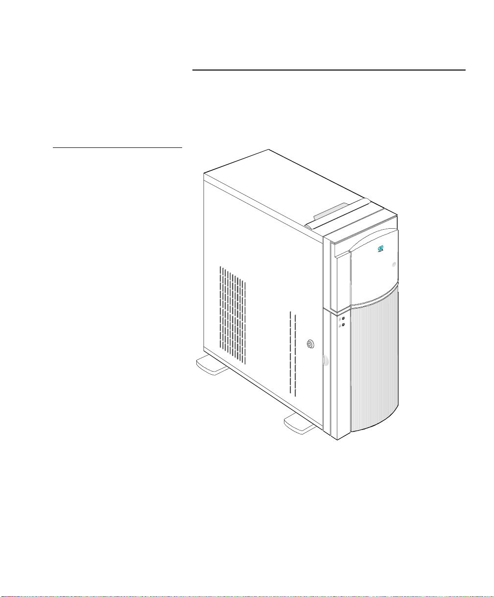
Figure 1-1
Front View
System Overview
System Features
System Features
This section describes major system features.
The system has the following minimum features:
System base board
•
350-watt power supply
•
NCR S10XL Hot Plug Server User Guide 1-3
Page 16

System Overview
System Features
• Seven I/O expansion slots (4 EISA, 2 PCI and
1 shared)
• Fast and Wide SCSI-2 controller integrated on the
system baseboard
• 25-pin and 9-pin serial ports
• 25-pin parallel port
• Keyboard and mouse ports
• One 3.5-inch 1.44 MB flex drive
• System cabinet
• Eight 3.5-inch hot plug bays and three 5.25-inch user
accessible bays, plus a bay for the 3.5-inch flex drive
1-4 NCR S10XL Hot Plug Server User Guide
Page 17

System Overview
Documentation Set
Documentation Set
The following docu ments are included wit h y o u r
system to help you install, upgrade, maintain, and
troubleshoot your system. Keep all documentation
together in a safe place.
• Quick Hardware Installation
This brochure provides yo u with in formation to
install your system quickly.
• User Guide
This is th e m a n u a l y ou a re now reading. It provides
you with more detailed information about your
system.
Caution
Drive, peripheral, CPU board, and adapter
•
documentation
If you have ordered optional features, such as
drives, peripheral devices, CPU boards, or adapters,
documentation for those items is packed with the
system. This documentation is important to
configure your system properly.
Do not discard any of this documentation. You may
need it again if your system ever requires service or you
change the configuration. Keep it in a safe place with
the other system documentation.
• Installing Network Operating System
This man u a l de s cribe s t h e procedures for installing
an operating system. You should also refer to the
NCR S10XL Hot Plug Server User Guide 1-5
Page 18

System Overview
Documentation Set
documentation that comes with your operating
system.
1-6 NCR S10XL Hot Plug Server User Guide
Page 19

System Overview
Getting Additional Help
Getting Additional Help
If you need additional help, refer to Appendix E of this
book.
NCR S10XL Hot Plug Server User Guide 1-7
Page 20

System Overview
Getting Additional Help
1-8 NCR S10XL Hot Plug Server User Guide
Page 21

Configuring the System Board
Overview
Overview
This chapter contains information about the following:
System board features
•
ESD precautions
•
Major components
•
Upgrading the memory
•
Insta llin g SIMMs
•
SCSI feature
•
Positioning the system
•
Rear panel features
•
Opening the sys tem
•
Insta llin g drives
•
Insta llin g a n d rem ov in g e x p a n sion boards
•
NCR S10XL Hot Plug Server User Guide 2-1
Page 22

Configuring the System Board
System Board Features
System Board Features
This high-performance system board supports the Intel
™
Pentium
not contain the CPU and the second-level cache.
Instead, it has a special slot designed to accommodate a
separate board that carries both the CPU and the
second-level cache. This feature gives maximum
upgrad a bility and flexibility t o your syst em.
Standard features such as two serial ports, one parallel
port, diskette drive interface, and embedded fixed dis k
drive interface reside on the system board.
The system board has a 0 MB base memory and
supports a max imu m m em ory of 128 MB u s ing 32 M B
single-density single inline memory modules (SIMMs).
A functional system is recommended to have at least 8
MB of RAM.
microprocessor. The main system board does
2-2 NCR S10XL Hot Plug Server User Guide
Page 23

Configuring the System Board
ESD Precautions
ESD Precautions
To avoid damag ing electronic equipment from
electrostatic discharge (ESD), always observe the
following precaution s before installing an y system
component:
Do not remove a board from its packag ing u ntil you
1.
are ready to install it.
Integrated circuits (ICs) on expansion boards are
highly sensitive to static electricity.
Wear a wrist g roun din g strap before handlin g
2.
electronic components. Wrist grounding straps are
available at most electronic component stores.
NCR S10XL Hot Plug Server User Guide 2-3
Page 24

Configuring the System Board
Major Components
Major Components
The system board has the following major components:
Four 72-pin SIMM sockets labeled Bank 0 and
•
Bank 1 (two sockets comprise one bank)
One CPU board slot
•
Four 32-bit EISA expansion slots supporting
•
master/slave add-on cards
Two PCI local bus slots
•
One shared slot (EISA or PCI)
•
128/256 KB Flash memory for easy sy s tem BI OS
•
upgrade
I/O interfaces for two s erial p orts , one parallel port,
•
peripheral drives, IDE drives, and one PS/2
keyboard and mouse
Onboard AIC-7870 chip that supp orts one SCSI -2
•
port
Power connector 1 for 350-watt switching power
•
supply
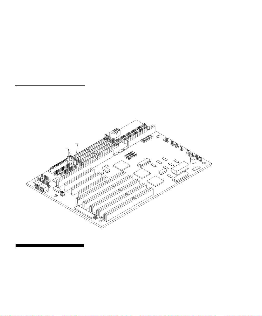
Figure 2-1 shows the location of the major components
on the system board.
2-4 NCR S10XL Hot Plug Server User Guide
Page 25

Figure 2-1
System Board Layout
Power Connector 1 (230 watt)
Fixed Disk Drive Interface
Diskette Drive Interface
Parallel Port Interface
Fast SCSI-2 Interface (narrow)
Fast SCSI-2 Interface (wide)
Power Connector 2
Configuring the System Board
Major Components
CPU Board Slot
Power LED Connector
Hard Disk LED Connector
Fan Connectors
JP5
Turbo Reset
Connector (J23)
JP6
COM 2
COM 1
PS/2
Keyboard Connector
PS/2
Mouse Connector
JP3
JP4
Jumper Settings
PCI Slots
Speaker
Connector (J24)
BIOS
EISA
JP1
JP2
Expansion Slots
You have to change the jumper settings on the sys tem
board when you upgrade the CPU or reconfigure the
system.
To change a jumper setting, follow these steps:
1.
Remove the jumper cap from the jumper.
2.
Position the jumper cap over the two pins for the
desired setting.
NCR S10XL Hot Plug Server User Guide 2-5
Page 26

Configuring the System Board
Major Components
3.
Gently press the cap over the pins.
Table 2-1 lists the sys tem board jumpers and their
corresponding settings. The asterisks indicate the
default settings.
Table 2-1
Jumper Settings
Jumper Setting Function
JP1 2-3* Standard System BIOS
JP2 1-2
2-3*
JP3 1-2*
2-3
JP4 1-2*
2-3
JP5 Open
Closed*
JP6 1-2*
2-3
Password enabled
Password disabled
DMA request 1 (DREQ1)
DMA request 3 (DREQ3)
DMA acknowledge 1 (DACK1)
DMA acknowledge 3 (DACK3)
Reset button disabled
Reset button enabled
Audio to buzzer
Audio to speaker
2-6 NCR S10XL Hot Plug Server User Guide
Page 27

Configuring the System Board
Upgrading the Memory
Upgrading the Memory
You can upgrade the system memory by adding single
inline memory modules (SIMMs) into the SIMM sockets
or by changing the SIMMs for a higher memory
configuration.
The four 72-pin SIMM sockets support 4 MB and 16 MB
single-density as well as 8 MB and 32 MB doubledensity SIMMs.
Table 2-2 lists the available memory configurations.
Table 2-2
Memory Configurations
Bank 0 Bank 1 Total
Socket 0 Socket 1 Socket 0 Socket 1 Memory
4 MB 4 MB 8 MB
8 MB 8 MB 16 MB
16 MB 16 MB 32 MB
32 MB 32 MB 64 MB
32 MB 32 MB 32 MB 32 MB 128 MB
Consider th e followin g when adding m e m ory:
Always install SIMMs from the lowest bank first.
•
For example, install SIMMs in bank 0 before bank 1.
Always remove SIMMs from the highest bank first.
•
For exa m ple, bank 1 be fo re ban k 0.
Use only the same type of SIMM in a given bank.
•
NCR S10XL Hot Plug Server User Guide 2-7
Page 28

Configuring the System Board
Upgrading the Memory
• You may combine different types of SIMMs for a
particular memory configuration as long as the
SIMMs in each bank are of the same type.
2-8 NCR S10XL Hot Plug Server User Guide
Page 29
Installing SIMMs
Note:
Configuring the System Board
Installing SIMMs
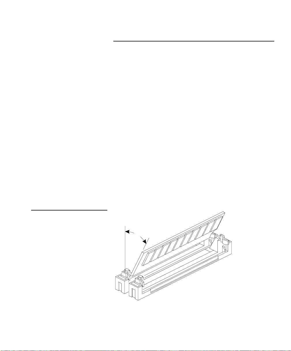
Figure 2-2
Installing a SIMM
Caution
Read the ESD precautions section earlier in this chapter
before proceeding .
To install a SIMM, follow these steps:
o
Slip a SIMM at a 45
1.
angle into a socket with the
component side facing down.
Gently press the SIMM up until the pegs of the
2.
socket slip into the holes on the SIMM and the
holding clips lock the SIMM into position.
The SIMM should be at a 90
o
angle when
installed on the baseboard or the dual processor
CPU board. The SIMM should be at a 45
o
angle
when inst alle d on th e ECC uni-processor C P U
board.
45°
NCR S10XL Hot Plug Server User Guide 2-9
Page 30
Configuring the System Board
Note:
Installing SIMMs
Figure 2-3
SIMM Sockets
SIMM Sockets
Bank 0
Bank 1
Always install SIMMs starting with Bank 0 and
in pairs. For examp le, for a total mem ory of 8 MB,
install two 4 MB SIMMs in sockets 0 and 1 of Bank 0.
You can not use an 8 MB SIMM alone for an 8 MB
memory.
To remove SIMMs, follow these steps:
Removing SIMMs
1. Press the holding clips on both sides of the SIMM
outward to release it.
2. Press the SIMM downward at about a 45
2-10 NCR S10XL Hot Plug Server User Guide
o
angle.
Page 31

Reconfiguring the System
Configuring the System Board
Installing SIMMs
3. Pull the SIMM out of the socket.
Reconfigure th e s ystem after installing or removing
SIMMs.
To reconfigure the system, follow these step s :
1.
Reboot the system. A memory error message
appears, indicating that the total memory does not
match the value stored in CMOS.
2.
Boot the sy s t em with the EISA Configuration U tilit y
(ECU) diskette, and configure the baseboard settings
for the proper amount of memory. Follow the step s
under the heading, “Configuring the System
Memory” in Chapter 5.
NCR S10XL Hot Plug Server User Guide 2-11
Page 32

Configuring the System Board
Note:
SCSI Feature
SCSI Feature
The system board features a single-chip Fast and Wide
SCSI-2 hos t a dap t er t h at add s SC SI I/O capability to th e
system.
The chipset consists of all the components found on the
state-of-the-art SCSI host adapters su ch as the
following:
Onboard microcontroller
•
Bus master interface controller
•
SCSI controller
•
The chipset allows transfers at a full 20 MB/second
burst transfer rate.
To us e the feature, install any SCSI device in your
system and connect it to the SCSI interface on the
system board. (See Figure 2-1 for the location.) Then,
enter the BI OS u tility to set the PCI slot parameters. See
Chapter 4 , “ Using the BIOS Set u p U tilit y ”, for details in
setting the parameters. Refer to the SCSI m anual for
more information on usin g SC SI.
Onboard terminators (RP12, RP13, and RP14)
must be removed when using wide drives. Ensure that
terminators are on when only narrow drives are used.
2-12 NCR S10XL Hot Plug Server User Guide
Page 33

Figure 2-4
Arranging the System in a Stable
Position (Bottom View)
Configuring the System Board
Positioning the System
Positioning the System
When positioning the system, arrang e the legs of the
housing so that the weight of the system is evenly
distributed and is stable.
NCR S10XL Hot Plug Server User Guide 2-13
Page 34

Configuring the System Board
Positioning the System
Figure 2-5
Allowing for Air Circulation (Bottom
View)
When standing the system with the fan against a wall,
leave a space of 5-10 cm from the wall to allow air
circulation, then pos ition the legs as in “Position A” of
Figure 2-5.
When standing the system with the fan facing out, you
can put the system close to the wall and position the
legs as in “ P osition B” of Figure 2-5.
Fan Fan
5 - 10 cm
2-14 NCR S10XL Hot Plug Server User Guide
Page 35

Figure 2-6
Rear Panel Features
Configuring the System Board
Rear Panel Features
Rear Panel Features
Figure 2-6 illustrates the rear p a n el fe at u res .
Voltage Switch
Power Socket
COM 1
COM 2
Printer
Keyboard Connector
Mouse Connector
Expansion Slots
External SCSI
Access
NCR S10XL Hot Plug Server User Guide 2-15
Page 36

Configuring the System Board
Opening the System
Opening the System
Figure 2-7
Opening the System
Caution
Read the “ESD Precautions” section earlier in this
chapter before proceeding.
Figure 2-7 illus t rat es how to open the s ystem. The k e y s
to the housing are inside the upper front panel.
2-16 NCR S10XL Hot Plug Server User Guide
Page 37

Figure 2-8
Note:
Opening the Cabinet Housing
Configuring the System Board
Opening the System
To op en th e s y s tem , follow these step s :
1.
Unlock the housing using the key and open the
lower front panel cover by pressing the button and
pulling t h e cov e r.
You can not remove the key after you have
unlocked t h e h ousing. You ca n rem ov e it on ly when
you lock the housing again.
2.
Pull on the k e y t o swing the left s ide of th e h ousing
open. If necessary, you may use a screwdriver
gently to pry the side of the housing open.
NCR S10XL Hot Plug Server User Guide 2-17
Page 38

Configuring the System Board
Installing Drives
Installing Drives
Caution
Removi ng the Upper Front Panel Cover and Frame
Figure 2-9
Removing the Upper Front Panel
Cover and Frame
Read the “ESD Precautions” section earlier in this
chapter before proceeding.
This sect ion d escribes in detail h ow t o install disk d riv es
in the system.
When installing drives on t h e 5 . 2 5 -in ch d riv e bays, you
have to remove both the upper front panel cover and its
frame. Follow these steps:
To remove the front panel cover, hold it on both
1.
sides and pull.
To remove the upper front panel frame, press the
2.
latch under it and pull as shown in Figure 2-9.
2-18 NCR S10XL Hot Plug Server User Guide
Page 39

Installing a 3.5-inch Peripheral Drive
Figure 2-10
Securing the Drive on the Frame
Configuring the System Board
Installing Drives
To install a 3 . 5 -in ch peripheral drive, follow these steps:
1. Remove the screw attaching the 3.5-inch drive frame
to the housing.
2. Secure the drive on the drive frame.
NCR S10XL Hot Plug Server User Guide 2-19
Page 40

Configuring the System Board
Installing Drives
Figure 2-11
Securing the Drive
3. Insert the drive into the third drive bay.
4. Secure it with a screw.
5. Connect the drive cables.
2-20 NCR S10XL Hot Plug Server User Guide
Page 41

Installing a 5.25-inch Peripheral Drive
Figure 2-12
Securing the Drive Guides
Configuring the System Board
Installing Drives
To install a 5 . 2 5 -in ch p e rip h e ra l driv e, follow these
steps:
1. Secure the drive guides on the sides of the
peripheral drive as shown in Figure 2-12.
2. Insert the drive into a 5.25-inch drive bay.
Figure 2-13
Inserting the Drive into the Drive
Bay
3.
Connect the drive cables.
NCR S10XL Hot Plug Server User Guide 2-21
Page 42

Configuring the System Board
Installing Drives
Removing a 5.25-inch Peripheral Drive
Figure 2-14
Pulling the Drive Out
To remove a 5.25-inch peripheral drive, follow these
steps:
1. Disconnect all the drive cables.
2. Press the metal tabs on the sides of the drive and
pull the drive out as shown in Figure 2-14.
2-22 NCR S10XL Hot Plug Server User Guide
Page 43

Installing a Hot Plug Fixed Disk Drive
Configuring the System Board
Installing Drives
To ins tall a hot plug fixed disk drive, refer to
Appendix D. The comp lete p rocedure is described
there.
NCR S10XL Hot Plug Server User Guide 2-23
Page 44

Configuring the System Board
Installing and Removing Expansion Boards
Installing and Removing
Expansion Boards
This section describes in detail the steps needed to
install ex p a n s ion boards in the sy s t em.
Caution
Identify i ng E x pa ns i on Boards
Read the “ESD Precautions” section earlier in this
chapter before proceeding.
There are three types of expansion boards:
EISA
•
ISA
•
PCI
•
Each expansion board has a different type of connector
See Figure 2-15.
An ISA board has a single row of contacts along its
connectors. There is usually a single notch in the
connector.
An EISA board has a double row of tightly spaced
contacts along its connector. There are usually six
notches (five small ones and one large one) in the
connector.
A PCI board has a single row of tightly spaced contacts
along its connectors. There is usually a single notch in
the conn e cto r.
2-24 NCR S10XL Hot Plug Server User Guide
Page 45

Figure 2-15
Expansion Board Connectors
Configuring the System Board
Installing and Removing Expansion Boards
Installing an Expansion Board
ISA board EISA board PCI board
To install an expansion board, follow these steps:
1.
Study the documentation that came with your
expansion board, and configure any jumpers or
switches on the board as directed.
NCR S10XL Hot Plug Server User Guide 2-25
Page 46

Configuring the System Board
Installing and Removing Expansion Boards
2.
Remove a bracket from any empty expansion slot.
Save the screw to secure the new board. Keep the
bracket for future use. See Figure 2-16 .
Figure 2-16
Removing a Bracket
2-26 NCR S10XL Hot Plug Server User Guide
Page 47

Configuring the System Board
Installing and Removing Expansion Boards
3.
Gently insert the board into an expansion slot. Make
sure the board is securely seated. See Figure 2-17.
4.
Secure the board with the bracket screw.
Figure 2-17
Installing a Board
Removing an Expansion Board
Caution
Do not neglect this step. The board uses the screw for
grounding.
To remove an expansion board, follow these steps:
1.
Unplug any cables connected to the board.
2.
Remove the bracket screw and pull the board out of
the slot.
3.
Secure a bracket cover to the empty slot with the
screw.
NCR S10XL Hot Plug Server User Guide 2-27
Page 48

Configuring the System Board
Installing and Removing Expansion Boards
2-28 NCR S10XL Hot Plug Server User Guide
Page 49

Understanding the CPU Boards
System Baseboard Support
System Baseboard Support
The system baseboard has one CPU board slot that
supports these two typ es of C PU boards:
CPU boards that support parity memory
•
CPU boards that support ECC memory
•
NCR S10XL Hot Plug Server User Guide 3-1
Page 50

Understanding the CPU Boards
s
Installing CPU Boards
Installing CPU Boards
If you ordered a CPU board factory-installed, you may
skip this chapter. If you must install a CPU board in
your system, read all of this information.
When actually performing the installation, refer to the
following docume n ts for information on ins t allin g CPU
boards in the system:
Warning
• Quick Hardware Installation
system
• Release Notes
Chapter 2 of this
•
CPU board slot on the system board (Figure 2-1)
When installing CPU boa rds, do not attempt to make
any hardware changes unless you are a qualified
technician. Ask your dealer for assistance.
There are two released versions of system BIOS. One
is for uniprocessor CPU boards, and the other is for
dual processor CPU boards. These versions of B IOS
are not interchange able . Flashing the incorrect versio n
renders the system unusable.
For example, if you flash the BIOS version released
for a uniprocessor CPU board on a system configured
with a dual CPU board you cannot use the system. I f
this happens, you must insert the appropriate CPU
board into the syste m a nd r ef lash the o r ig ina l B IOS.
that came with your CPU board
User Guide
that came with your
for the location of the
3-2 NCR S10XL Hot Plug Server User Guide
Page 51

Understanding the CPU Boards
Installing CPU Boards
Refer to the diskette labe l to m ake sure y o u a r e using
the appropriate BIOS for your system configuration.
NCR S10XL Hot Plug Server User Guide 3-3
Page 52

Understanding the CPU Boards
Installing CPU Boards
3-4 NCR S10XL Hot Plug Server User Guide
Page 53

Using the BIOS Setup Utility
Note:
When to Use the BIOS Setup Utility
When to Use the BIOS Setup
Utility
Most systems are already configured by the
manufacturer or the dealer. There is no need to run th e
BIOS Setup u tilit y p rogram wh en starting the comp u te r
unless you get a Run Setup message.
Run BIOS Setup wh en y ou wan t to do on e or m ore of
the following:
Install or remove a PCI adapter
•
Install or remove an IDE disk drive
•
Change the display type
•
Change the password or security features
•
Change the CPU s p eed
•
Disable or enable the cache memory
•
Reserve the top 1 MB of system memory
•
Set the date and time
•
Setup loads configuration values into the batterybacked, n on v ola tile m e m ory called CMOS RAM. This
memory area is not part of the system RAM.
For information about adding or removing memory
refer to the “Usin g t h e E I SA Configura tion U t ility”
section of Chapter 5.
If you re peatedly recei ve Ru n Set up er ror
NCR S10XL Hot Plug Server User Guide 4-1
Page 54

Using the BIOS Setup Utility
When to Use the BIOS Setup Utility
messages, check the comp u ter's internal battery. If the
battery is dead or not properly connected, the system
cannot retain configuration values in CMOS RAM .
Before running Setup, have the following information
ready:
• Diskette drive type. The standard type is a 3.5-inch
1.44 MB diskette drive. A 5.25-inch 1. 2 M B drive is
supported.
• Fixed disk drive type. The drive inform ation is on a
label pasted to your disk drive or in the
documentation that comes with your disk drive.
Refer also to Table 4-6 at the end of this chapter.
4-2 NCR S10XL Hot Plug Server User Guide
Page 55

Using the BIOS Setup Utility
Entering Setup
Entering Setup
Power up the system. When the “Press Ctrl-Alt-Esc key
to enter Setup” message displays, press the key
combination [Con t rol] + [Alt] + [Esc] to enter Setup.
You do not need to insert a diskette or load an operating
system. Just press the key combination.
Figure 4-1 shows the BIOS Setup main menu.
Figure 4-1
BIOS Setup Main Menu
BIOS Utility
Basic System Configuration
Advanced System Configuration
PCI System Configuration
System Security
Load Setup Default Settings
= Move Highlight Bar, = Select, Esc = Exit and Reboot
NCR S10XL Hot Plug Server User Guide 4-3
Page 56

Using the BIOS Setup Utility
Basic System Configuration
Basic System Configuration
Select Basic System Configuration to input
configuration values such as date, time, and disk types .
Figure 4-2 shows Page 1 of the Basic System
Configuration menu.
Figure 4-2
Basic System Configuration Menu
(Page 1 of 2)
Basic System Configuration
Date
Time
Diskette Drive A
Diskette Drive B
Hard Disk 0 (0MB)
Hard Disk 1 (0MB)
= Move Highlight Bar,
PgDn/PgUp = Move Screen, F1 = Help, Esc = Exit
[00-00-00]
[00:00:00]
[1.44 MB 3.5 inch]
[None]
Cylinder
[None]
[None]
Head
= Change setting,
Sector
Page 1/2
The command line at the bottom of the display has
three functions. It tells you how to view the
configuration options for each parameter, how to move
the highlight bar from one parameter to the next, and
how to change the value for each parameter.
Press the up- or down-arrow keys to highlight the
1.
desired parameter.
4-4 NCR S10XL Hot Plug Server User Guide
Page 57

Using the BIOS Setup Utility
Basic System Configuration
2. Press the [Page Down] key to move to the next
page, or press the [Page Up] key to return to the
previous page.
3. After you select the desired option for a given
parameter, press the ap p ropriate arrow key to
highligh t t h e n e x t p a ra m et er. This option is n ow set
as the configuration value.
Figure 4-3 shows Page 2 of the Basic System
Configuration menu.
Figure 4-3
Basic System Configuration Menu
(Page 2 of 2)
Basic System C onfiguration
Communication Settings
Baud Rate
Parity
Stop Bits
Data Lengths
EnhancedIDE Features
Hard DiskBlock Mode
AdvancedP10 Mode
Hard Disk Size > 504MB
Hard Disk32 Bit Access
Num Lock After Boot
Memory Test
Auto ConfigMode
Fast Boot Mode
= Move Highlight Bar,
PgDn/PgUp = Move Screen, F1 = Help, Esc = Exit
[9600] BPS
[None]
[1] Bits
[8] Bits
[Disabled]
[Disabled]
[Disabled]
[Disabled]
[Enabled]
[Enabled]
[Disabled]
[Disabled]
= Change setting,
Page 2/2
To use the Help option, press [F1]. A window displays
on the screen with a brief description of the currently
highlighted parameter.
The following sections explain the different parameters
and their settings.
NCR S10XL Hot Plug Server User Guide 4-5
Page 58

Using the BIOS Setup Utility
Basic System Configuration
Date and Time
The real-time clock keep s the s y s tem date and time.
After setting the date and time, you need not enter
them every time you turn on the system unit. As long
as the internal battery remains good (approximately
seven years) and connect e d , t h e clo ck co n t in ues to keep
the date and time accurately even when the power is
off.
Date
Highlight this parameter to set the date. Enter the
current date, following the m onth-day-year format.
Whenever you want to change the date, simply
highlight the Date parameter and enter the new date.
Valid values for month, day, and year are as follows:
• Month 1 to 12
• Day 1 to 31
• Year 00 to 99
Time
Highlight this parameter and enter the current time in
the hour-minute-second format to set the time.
Whenever you want to change the time, simply
highlight the Time parameter and enter the new time.
Valid values for hour, minute, and second are as
follows:
• Hour 00 to 23
• Minute 00 to 59
4-6 NCR S10XL Hot Plug Server User Guide
Page 59

Diskette Drives
Using the BIOS Setup Utility
Basic System Configuration
• Second 00 to 59
To enter the configuration value for the first diskette
drive (drive A), highlight the Disk ette Drive A
parameter. Press the left- or right-arrow key to view the
options and select the appropriate value.
The Diskette Drive A parameters have the following
options:
• None
• 360 KB, 5.25-inch
• 1.2 MB, 5.25-inch
• 720 KB, 3.5-inch
• 1.44 MB, 3.5-inch
• 2.88 MB, 3.5-inch
IDE Fixed Disk Drives
Follow the same procedure to enter the value for the
Diskette Drive B parameter. Choose None if you do not
have a second diskette drive.
Move the highlight bar to the Fixed Disk 0 parameter to
configure the IDE fixed disk drive (drive C). Use the left
or right arrow key to display the IDE fixed disk options
with their respective values. Select an option that
corresponds to your IDE fixed disk type. Follow the
same procedure to enter the values for the IDE Fixed
Disk 1 parameter. Choose None if you do not have a
second fixed disk drive.
If you do not know the exact type of your I D E fixed
disk, select the option Auto. When you select this
NCR S10XL Hot Plug Server User Guide 4-7
Page 60

Using the BIOS Setup Utility
Note:
Basic System Configuration
option, th e B I OS u t ility automatically det ermines the
type of your IDE fixed disk during POST. You can see
your IDE fixed disk values when you enter the BIOS
Utility.
Cylinder Head Sector
Fixed Disk 0 (xx MB) [Auto] xx xx xx
You can save the values under the option User.
Cylinder Head Sector
Fixed Disk 0 (xx MB) [User] xx xx xx
The next time y ou boot th e system, th e BIOS utility
does not have to auto-configure your IDE fixed disk as
it detects the saved IDE fixed disk inform ation du ring
POST.
We recommend that you copy the IDE fixed
disk values and keep them in a safe place in case you
have to reconfigure the disk in the future.
Follow the same procedure to auto-configure other
installed IDE fixed disk s .
However, there are cases when you cannot use the
option Auto, instead you have to select User. This is
when you installed an IDE fixed disk that was
previously formatted but not using the disk native
parameters or structure. The IDE disk type may be in
the fixed disk type list but the number of cylinders,
heads, and sectors are not exactly the same.
Before using the User option, obtain the correct IDE
fixed disk information.
4-8 NCR S10XL Hot Plug Server User Guide
Page 61

System Memory
Using the BIOS Setup Utility
Basic System Configuration
To use the User option, follow these steps:
1.
Highlight the User option.
2.
Type in the number of cylinders, heads, and sectors
of the IDE fixed disk .
3.
Choose YES when asked if you want to save CM OS
data.
The system automatically detects the total amount of
onboard memory and sets the corresponding value in
the Setup program. This information is not adjustable
by the user and is for display only. When y ou ins tall
additional memory, the s y s tem au tomatically updates
the Total Mem ory p aram eter to s how the new mem ory
size.
Math Coprocessor
Video Display
The CPU includes a math coprocessor so this parameter
shows Installed by default.
The video display is the monitor on which the operating
system prompt displays when you boot the system. The
system automatically detects the video mode of your
primary display and sets the configuration value
accordingly. The values are as follows:
• Monochrome
• CGA 40 columns x 25 rows
• CGA 80 columns x 25 rows
• VGA/EGA
NCR S10XL Hot Plug Server User Guide 4-9
Page 62

Using the BIOS Setup Utility
Basic System Configuration
Communication Settings
The Communication Settings parameters let you set the
baud rate, parity, stop bit and data length for the first
serial port (COM 1). The values are as follows:
• Baud rate: 300 to 38,400 bits per second (BPS)
• Parity: odd, even, or none
• Stop bit: 1 or 2 stop bits
• Data length: 7- or 8-bit data word
There is one restriction on the options available for the
communication status parameters. I f your data length
parameter is an 8-bit data word, you must select one of
the following com bina tion s:
• 1 stop bit and odd or even parity
• 2 stop bits and no parity
The default values are 9600 BPS, odd parity, 1 s top bit,
and 8-bit data word.
This function enhances disk performance depending on
Hard Disk Block Mode
4-10 NCR S10XL Hot Plug Server User Guide
the fixed disk in use. If you set this parameter to
Enabled, it allows data transfer in block (multiple
sectors) by increasing the data transfer rate to 256
bytes/cycle. If your system does not boot after enabling
this parameter, change the setting to Disabled. Disable
the parameter if your system disk does not support this
function.
Page 63

Advanced PIO Mode
Hard Disk Size > 504 MB
Hard Drive 32-Bit Access
Using the BIOS Setup Utility
Basic System Configuration
Enabling this parameter allows for faster data recovery
and read/write timing that reduces Fixed D isk activity
time. This results in better fixed disk performance. To
use this feature, your fixed disk must support the
advanced PIO mode. If not, set this to Disabled.
This enhanced IDE feature only works under DOS and
Windows 3.x environment. If enabled
use a fixed disk with a capacity of more than 504 MB.
This is made possible through the Logical Block
Address (LBA) mode translation. Other operating
systems require this parameter be set to Disabled.
If enabled, t h is parameter allows h a rd drive 32 -bit
access.
,
it allows you t o
Num Lock After Boot
Memory Test
Auto-Configuration Mode
This parameter allows you to activate the Num Lock
function upon system boot.
The system performs a RAM test during the power-on
self-test (POST) routine. Set this parameter to Disabled
to bypass this test routine. The default setting is
Enabled.
Set this parameter to Enabled if you do not know the
fixed disk drive type parameters and the onboard
communication port configuration. When set to
Enabled
to Auto and the System Speed to High, and enables the
NCR S10XL Hot Plug Server User Guide 4-11
,
this parameter sets the fixed disk drive ty pe
Page 64

Using the BIOS Setup Utility
Basic System Configuration
Fast Boot Mode
system and video RAM, as well as the primary- and
second-level cache. The default setting is Disabled.
This parameter allows the system to boot faster by
skipping some POST routines. If enabled, it sets the
System Speed to High, and enables Shadow RAM, and
primary- and second-level cache. The default setting is
Disabled.
4-12 NCR S10XL Hot Plug Server User Guide
Page 65

Using the BIOS Setup Utility
Advanced System Configuration
Advanced System
Configuration
Select the Advanced System Configuration option to
configure the system memory. Figure 4-4 shows Page 1
of the Advanced Sys tem C onfiguration menu.
Figure 4-4
Advanced System Configuration
Menu (Page 1 of 3)
Shadow RAM
Advanced SystemConfiguration
ShadowRAM
E0000h - FFFFFh (System Bus)
C0000h - C7FFFh (Video Bus)
C8000h - CFFFFh
D0000h - D7FFFh
D8000h - DFFFFh
Internal Cache
ExternalCache
Cache Scheme
System Me mory Parity
Memory at 15MB- 16MB Reserved for
E0000h - FFFFFh (System BIOS)
C0000h - C7FFFh (Video BIOS)
= Move Highlight Bar,
PgDn/PgUp = Move Screen, F1 = Help, Esc = Exit
[Enabled]
[Enabled]
[Disabled]
[Disabled]
[Disabled]
[Enabled]
[Enabled]
Write Ba c k
[Enabled]
[System] use
[Cacheable]
[Cacheable]
= Change setting,
Page 1/3
The system reserves 384 KB of random access mem ory
(RAM) for the shadow RAM function. This parameter
has seven range addresses.
When you set these addresses to Enabled, the system
BIOS, video BIOS, an d I / O ROM functions run directly
from the shadow RAM for faster operation. When you
set them to Disabled, the functions run normally from
ROM.
NCR S10XL Hot Plug Server User Guide 4-13
Page 66

Using the BIOS Setup Utility
Advanced System Configuration
The address E0000h - FFFFFh is for system BIOS and
C0000h - C7FFFh is for shadowing video BIOS. The
remaining address ranges are for I/O ROM functions.
Internal Cache (CPU Cach e)
This parameter enables/disables the internal cache
memory. The default setting is Disabled.
External Cache
This parameter enables/disables the external cache
memory. The default setting is Disabled.
Cache Scheme
This parameter is not configurable and sets the cache to
Write-ba ck mode. Write-back updates the cache bu t not
the mem ory wh e n t h ere is a write in s t ru ct ion . It
updates the memory only when there is an
inconsistency between the cache and the memory.
This parameter enables/disables the system from
System Memory
responding to memory parity errors.
Parity
To prevent memory address conflicts between the
Memory at 15 MB16 MB
E0000h - FFFFFh (System BIOS)
4-14 NCR S10XL Hot Plug Server User Guide
system and expansion boards, reserve this memory
range for the use of either the sys tem or an ex p an s ion
board.
If the System BIOS parameter is set to Enabled, you
may select Cacheable or Non-cacheable for the E0000hFFFFFh parameter. When set to Cacheable, it allows the
Page 67

C0000h - C7FFFh (Video BIOS)
Guaranteed Access Time (Parity Memory Only)
Using the BIOS Setup Utility
Advanced System Configuration
system BIOS to run directly from the cache memory.
The system operates faster. When set to Non-cacheable,
it lets the system BIOS run from RAM.
If the Video BIOS param eter is s et to Enabled, you m ay
select Cacheable or Non-cacheable for the C0000hC7FFFh parameter. When set to Cacheable, it allows the
video BIOS to run directly from the cache memory. The
system operates faster. When set to Non-cacheable, it
lets the video BIOS run from RAM.
With this parameter s et to Enabled, the sy s tem
guarantees that the ISA 2.1 microseconds CHRDY
specification is n o t v iolat ed . Th is is crucial for some
timing-critical expansion boards. Note that enabling this
parameter slightly decreases the concurrency of PCI bus
and EISA bus.
Highest Priority Device for PCI Arbitration (Parity Memory Only)
This parameter allows PCI bus arbitration to decide
which master device supported by the bus can own it at
a specific time.
There are basically two arbitration modes for PCI bus
masters:
• Fixed – can be CPU or EISA/IO. The CPU and
EISA/IO are the two possible highest priority
devices. When set to either of these options, and
there is more than one device requesting the bus, the
master device obtains the bus according to its fixed
priorities.
NCR S10XL Hot Plug Server User Guide 4-15
Page 68

Using the BIOS Setup Utility
Advanced System Configuration
• Rotation – each of the master devices obtains the
PCI bus when its turn to own the bus comes. In this
option, all the master devices have the same priority
on PCI bus ownership.
4-16 NCR S10XL Hot Plug Server User Guide
Page 69

Using the BIOS Setup Utility
PCI System Configuration
PCI System Configuration
Figure 4-5 shows the screen that appears when you
select the PCI System Configuration menu from the
BIOS Utility menu.
Figure 4-5
PCI System Configuration Menu
(Page 1 of 1)
PCI Slot Number
[--]
[--]
[--]
[--]
Page 1/1
INTD
[--]
[--]
[--]
[--]
PCI System Configuration
PCI IRQ Setti ng
PCI Slot 1
PCI Slot 2
PCI Slot 3
On Boar d SCSI
VGA Palette Snoop
On BoardSCSI AIC-7870
Boot Device
= Move Highlight Bar,
PgDn/PgUp = Move Screen, F1 = Help, Esc = Exit
[Manual]
INTA
[--]
[--]
[--]
[--]
[Disabled]
[Enabled]
[Enabled]
= Change setting,
INTB
[--]
[--]
[--]
[--]
INTC
Each PCI slot supports four interrupt pins. The INTA
pin is automatically reserved for Function Number 0
(master function). The remaining interrupt pins (INTB,
INTC, and INTD) are reserved for multifunction. Refer
to your card manual for the interrupt pin assignments.
This parameter as signs the IRQ level for each in terru p t
pin of the PCI slots. You can assign any of the following
available IRQ levels: 3, 5, 9, 10, 11, 14, and 15.
NCR S10XL Hot Plug Server User Guide 4-17
Page 70

Using the BIOS Setup Utility
PCI System Configuration
VGA Palette Snoop
On Board SCSI
PCI devices support the “palette snooping” technique
that enables the device to control access to their palette
registers.
Set this parameter to Enabled to activate the palette
snooping function in the P CI VGA devices installed in
your system. Check your VGA card manual for more
information about this function.
This parameter enables/disables the on board SCSI
AIC-7870.
Boot Device
During POST, the normal booting procedure starts with
the initialization of the ISA card, followed by the PCI
card, then the onboard SCSI , if present. Enabling this
parameter changes the normal booting sequence of the
system, doing the SC SI initialization prior to add-on
PCI card initialization. You can only set this parameter if
the On Board SCSI parameter is set to Enabled. The
default setting is Disabled.
4-18 NCR S10XL Hot Plug Server User Guide
Page 71

Using the BIOS Setup Utility
System Security Setup
System Security Setup
The Setup program has a number of security features to
prevent unauthorized access to the system and its data.
Enter the Setup program and select System Security.
The screen in Figure 4-6 displays.
Figure 4-6
System Security Menu (Page 1 of
1)
Disk Drive Control
System Security
Disk Drive Control
Diskette Drive
Hard Disk Drive
System Boot Drive
Onboard Communication Ports
SerialPort1BaseAddress
SerialPort2BaseAddress
Parallel Port Base Address
Operation Mode
EPPVersionSelection
Setup Password
Power-on Password
= Move Highlight Bar,
PgDn/PgUp = Move Screen, F1 = Help, Esc = Exit
[Normal]
[Normal]
[Drive A then C]
[3F8]
[2F8]
[Parallel 1 (3BCh)]
[Standard Pa rallel Port (SPP)] Mode
[1.7]
[None]
[None]
= Change setting,
Page 1/1
Press the up- or down-arrow key to highlight from one
parameter to the next. Press the right- or left-arrow key
to change the setting.
The disk driv e con t rol featu res a llow y ou t o e n able or
disable the read/write functions of a disk drive. Thes e
features can also control the diskette drive or fixed disk
drive boot function to prevent loading operating
systems or other programs from a certain drive while
the other drives remain operational.
NCR S10XL Hot Plug Server User Guide 4-19
Page 72

Using the BIOS Setup Utility
Note:
System Security Setup
Table 4-1 lists the functions of the drive control settings.
Table 4-1
Drive Control Settings
Diskette Drive
Normal Diskette drive functions normally
Write Protect All
Sectors
Write Protect Boot
Sector
Disabled Disables all diskette functions
Fixed Disk Drive
Normal Fixed disk drive functions
Write Protect All
Sectors
Write Protect Boot
Sector
Disabled Disables all fixed disk functions
Disables the write function on all
sectors
Disables the write function only
on boot sector
normally
Disables the write function on all
sectors
Disables the write function only
on boot sector
System Boot Drive
Drive A then C System boots from drive A to C
Drive C then A System boots from drive C to A
C: System always boots from drive
C
A: System always boots from drive
A
The drive control settings that you specify take
4-20 NCR S10XL Hot Plug Server User Guide
Page 73

Onboard Communi ca tion Ports
Using the BIOS Setup Utility
System Security Setup
effect only if the diskette and fixed disk controllers are
not disabled through jumper settings.
There are three onboard communications ports:
• Serial Port 1
• Serial Port 2
• Parallel Port
Serial Port 1
This parameter enables serial port 1 as COM 1 and s ets
its address. Table 4-2 lists the Serial Port 1 settings.
Table 4-2
Serial Port 1 Settings
Setting Function
Serial 1 (3F8h) COM1 with address 3F8h
Serial 2 (2F8h) COM2 with address 2F8h
Serial 3 (3E8h) COM3 with address 3E8h
Serial 4 (2E8h) COM4 with address 2E8h
Disabled Disables serial port 1
NCR S10XL Hot Plug Server User Guide 4-21
Page 74

Using the BIOS Setup Utility
System Security Setup
Serial Port 2
This parameter enables serial port 2 and sets its address.
Table 4-3 lists the Serial Port 2 settings.
Table 4-3
Serial Port 2 Settings
Table 4-4
Parallel Port Settings
Setting Function
Serial 1 (3F8h) COM1 with address 3F8h
Serial 2 (2F8h) COM2 with address 2F8h
Serial 3 (3E8h) COM3 with address 3E8h
Serial 4 (2E8h) COM4 with address 2E8h
Disabled Disables serial port 2
Parallel Port
The sys te m h a s on e p a ralle l p ort . Th e followin g t able
lists the op tion s for selecting the p ara llel port address.
You also have the option to disable the parallel port.
Table 4-4 lists the Parallel Port settings.
Setting Function
3BCh Corresponds to the parallel port 1
with address 3BCh
378h Corresponds to the parallel port 2
with address 378h
278h Corresponds to the parallel port
with address 278h
Disabled Disables the parallel port
4-22 NCR S10XL Hot Plug Server User Guide
Page 75

Using the BIOS Setup Utility
System Security Setup
To deactivate the parallel port, select the Disabled
option. If you install an add-on card that has a parallel
port whose a ddres s con flict s wit h th e p a ralle l p ort
onboard, the system automatically disables the onboard
functions.
Check the parallel port address on the add-on card and
adjust the address to one that does not conflict.
Operation Mode
This item allows you to set the operation mode of the
parallel port. Table 4-5 lists the different operation
modes of the parallel port.
Table 4-5
Parallel Port Operation Modes
Setting Function
Standard Parallel Port
(SPP)
Enhanced Parallel Port
(EPP)
Extended Capabilities
Port (ECP)
Standard and
Bidirectional
EPP Version Selected Allows selection of either EPP
Allows normal speed operation
but in one direction only
Allows bidirectional parallel port
operation at maximum speed
Allows parallel port to operate in
bidirectional mode and at a
speed higher than the maximum
data transfer rate
Allows normal speed operation
in a two-way mode
Version 1.7 or 1.9 if the
Operation Mode of the Parallel
Port is set to Enhanced Parallel
Port (EPP)
NCR S10XL Hot Plug Server User Guide 4-23
Page 76

Using the BIOS Setup Utility
Note:
System Security Setup
Setup Password
This option lets you set a pas s word to prevent
unauth orize d a cce s s to the BIOS Utilit y.
Setting a Password
To set a password, follow these steps:
1.
Highlight the Setup Password parameter and press
the left- or right-arrow key to display the password
prompt.
2.
Type a password. The password may consist of up
to seven characters.
Be careful when typing your password
because the characters do not appear on the screen
when you type them.
3.
Press [Enter]. Another prompt as k s y ou to retype
the password to verify your first entry.
4.
Retype the password, and press [Enter].
After setting the password, the system autom atically
sets the Setup Password parameter to Present. The next
time you wan t to en t er t h e B I OS U t ility, you must keyin your setup password. Write down your password
and keep it in a secure place.
Caution
Power-On Password
4-24 NCR S10XL Hot Plug Server User Guide
If you forget your password, you have to reset the
configuration values stored in BIOS Setup to their
default values. Ask your dealer for assistance.
This parameter allows you to set the system password.
The power-on password secures your system against
Page 77

Using the BIOS Setup Utility
Note:
System Security Setup
unauthorized users. Once you set this password, you
have to type it whenever you boot the system.
To set the power-on password, follow the same
procedures as in setting the setup password.
To enable the password function, you must
strap pins 1-2 on JP2 located on the system baseboard.
The factory default setting disables the password
function with pins 2-3 strapped. See Figure 2-1 in
Chapter 2 for the location of JP2.
To change the ex isting p ass word, enter the current
password at the prompt when you boot the system,
followed by a slash (/) and the n ew password you wish
to specify. Again, be careful when typing the password
as it does not appear on screen when you enter it.
NCR S10XL Hot Plug Server User Guide 4-25
Page 78

Using the BIOS Setup Utility
Loading Setup Default Settings
Loading Setup Default S e ttings
This parameter loads the default values to the sys tem
configuration parameters. The default values are the
optimized configuration settings for the system.
Enabling the Auto Configuration Mode and the Fast
Boot Mode parameters under the Basic System
Configuration menu allows this function to set the
System Speed, Shadow RAM, Cache, and other system
parameters to their default settings.
4-26 NCR S10XL Hot Plug Server User Guide
Page 79

Using the BIOS Setup Utility
Leaving Setup
Leaving Setup
Examine the system configuration values. When you
are satisfied that all the values are correct, write them
down. Store the recorded values in a safe place, such as
in this manual. In the future, if the battery loses power,
or the CMOS ch ip is damaged, you will know wha t
values to enter when you rerun Setup.
To leave the sys tem configuration setup, follow these
steps:
Press [Esc] to leave setup.
1.
If there is an y change in th e B I OS U t ilit y fu n ct ion s,
2.
you must choose to save or not s ave any changes .
Use the arrow keys to select your response.
Select Yes to store the new data in BIOS Setup. Select
No to retain the old configuration values.
Press [Enter].
3.
NCR S10XL Hot Plug Server User Guide 4-27
Page 80

Using the BIOS Setup Utility
Fixed Disk Types
Fixed Disk Types
Table 4-6 lists values for the fixed disk ty p es .
Table 4-6
Fixed Disk Types
Type Cylinders Heads Sectors Per Track
0 (indicates SCSI or no fixed disk)
1 306 4 17
2 615 4 17
3 615 6 17
4 940 8 17
5 940 6 17
6 615 4 17
7 462 8 17
8 733 5 17
9 900 15 17
10 820 3 17
11 855 5 17
12 855 7 17
13 306 8 17
14 733 7 17
4-28 NCR S10XL Hot Plug Server User Guide
Page 81

Using the BIOS Setup Utility
Fixed Disk Types
Type Cylinders Heads Sectors Per Track
15 (reserved)
16 612 4 17
17 977 5 17
18 977 7 17
19 1024 7 17
20 733 5 17
21 733 7 17
22 733 5 17
23 306 4 17
24 612 4 17
25 306 4 17
26 612 4 17
27 698 7 17
28 976 5 17
29 306 4 17
30 611 4 17
31 732 7 17
32 1023 5 17
NCR S10XL Hot Plug Server User Guide 4-29
Page 82

Using the BIOS Setup Utility
Fixed Disk Types
Type Cylinders Heads Sectors Per Track
33 751 8 17
34 755 16 17
35 731 13 26
36 980 15 17
37 936 16 17
38 981 5 17
39 981 10 17
40 762 8 39
41 980 5 17
42 832 8 33
43 683 12 38
44 513 16 38
45 776 8 33
46 683 16 38
47 832 6 33
48 615 2 34
49 989 16 63
50 823 4 38
4-30 NCR S10XL Hot Plug Server User Guide
Page 83

Using the BIOS Setup Utility
Fixed Disk Types
Type Cylinders Heads Sectors Per Track
51 1001 15 17
52 1024 17 22
53 723 13 51
54 548 8 38
55 1013 4 41
56 929 15 17
57 817 14 36
58 723 13 81
59 802 4 39
60 1024 9 17
61 895 5 55
62 (reserved)
63 966 10 34
64 1024 8 17
65 1024 11 17
66 918 11 17
67 905 9 17
68 1024 10 17
NCR S10XL Hot Plug Server User Guide 4-31
Page 84

Using the BIOS Setup Utility
Fixed Disk Types
Type Cylinders Heads Sectors Per Track
69 1024 12 17
70 1024 13 17
71 1024 14 17
72 1024 2 17
73 1024 16 17
74 918 15 17
75 820 6 17
76 1024 5 17
77 1024 8 17
78 (reserved)
79 1001 15 32
80 1024 16 63
81 1024 10 17
82 1024 11 17
83 1024 15 17
84 776 8 33
85 926 13 17
86 805 4 26
4-32 NCR S10XL Hot Plug Server User Guide
Page 85

Using the BIOS Setup Utility
Fixed Disk Types
Type Cylinders Heads Sectors Per Track
87 976 5 17
88 745 4 28
89 747 2 28
90 782 2 1Bh
91 985 13 32
92 816 15 32
93 968 5 17
94 903 8 46
95 966 5 34
96 535 10 50
97 715 10 50
98~100 (reserved)
Auto or
(user-defined)
User
NCR S10XL Hot Plug Server User Guide 4-33
Page 86

Using the BIOS Setup Utility
Fixed Disk Types
4-34 NCR S10XL Hot Plug Server User Guide
Page 87

Using the System Utilities
Note:
Identifying the System Utilities
Identifying the System Utilities
This chapter contains information about the system
utilities t h a t a re u s e d when upgrad in g your system.
These ut ilitie s a re as follows:
AFlash B I OS U t ility
•
EISA Configuration Utilit y (E C U )
•
The AFlash BIOS U tilit y d is k e tt e d oes not come
with the system packag e. Ask your dealer if you need
the utility.
NCR S10XL Hot Plug Server User Guide 5-1
Page 88

Using the System Utilities
Using the AFlash BIOS Utility
Using the AFlash BIOS Utility
This section con t ain s information on us in g t h e AFlas h
BIOS utility.
Functions
Warning
When installing CPU boa r ds be a war e o f the
following:
Do not install memory-related driver s (X M S, EMS, or
DPMI) when you use A f lash.
There are two released versions of system BIOS. One
is for uniprocessor CPU boards, and the other is for
dual processor CPU boards. These versions of B IOS
are not interchangeable. Flashing the inco r r ect v e rsio n
renders the system unusable.
For example, if you flash the version released for a
uniprocessor CPU bo a rd o n a sy ste m co nfigured with
a dual processor CPU board, you cannot use the
system. I f this h a pp en s, you must insert th e
appropriate CPU board into the system and reflash the
original BIOS.
Refer to the diskette labe l to m ake sure y o u a r e using
the appropriate BIOS for your system configuration.
The AFlash BIOS utilit y h a s th ree fun ction s t h at s u p p o rt
all the operations required for sys tem F lash R OM
directly from or to the DOS file:
5-2 NCR S10XL Hot Plug Server User Guide
Page 89

Procedure
Using the System Utilities
Using the AFlash BIOS Utility
• Loads the BIOS file to the buffer - reads the s p ecified
file from a diskette to memory for future program
use or for check only. I t s u pp orts the 64 KB, 128 KB,
192 KB or 256 KB files.
• Saves the BIOS to a disk file - reads the BIOS from
the current BI OS a rea an d write s it t o a file specified
by the user.
• Programs the flash memory - programs the Flash
memory according to the data loaded in drive A.
This function also shows the BIOS checksum and
the BIOS type to make sure that the operation is
correct.
To u s e th e Aflash BIOS utility, follow these step s :
1.
Copy the MSG.DAT and AFLASH.EXE files from
the system utilities diskette into a s u bd irectory of
your cho ice .
2.
From that subdirectory, type “aflash” and press
[Enter].
3.
A help message displays. Press any key to continue.
4.
The main menu displays. Use the up- or downarrow keys to highlight the options. Press [Enter] to
select. If warnings or error messages appear, press
any key to continue or quit.
5.
If you want to save a copy of the current BIOS into a
file, select Save BIOS to Disk File.
6.
Select Load BIOS File to load the BIOS file into
memory.
NCR S10XL Hot Plug Server User Guide 5-3
Page 90

Using the System Utilities
Using the AFlash BIOS Utility
7.
Select Program Flash Memory to erase the current
BIOS, and program Flash R OM .
Warning
Do not turn off sy ste m power while Flash BIOS is
programming. This destroy s the BIOS.
8.
Reboot the system.
A quicker way to load the BI OS file in to m emory, an d
program the Aflash ROM is to type “c:\aflash
[filename]” and press [Enter].
The program automatically performs the loading and
programming functions, then reboots the system.
If the program cannot find the BIOS file, it shows the
main menu and flashes this message:
Can't Read This File !!! Press any key to
continue...
Follow the procedures for loa din g a n d p rogramming
BIOS file using the main m e n u .
5-4 NCR S10XL Hot Plug Server User Guide
Page 91

Using the System Utilities
Note:
Using the EISA Configuration Utility
Using the EISA Configuration
Utility
The EISA Configuration U t ility (ECU) configures y ou r
computer and the boards or options added to the
system.
The ECU does the following:
Resolves conflicts between DMA channels, interrupt
•
(IRQ) lines, I/O port addresses, and memory
requirements
Presents the option settings that specify those
•
parameters
Presents settings for other functions that are
•
necessary or desirable to make the presentation
useful
The EISA Configuration U t ility (ECU) does not
set the IRQ levels for PCI adapters. Us e the BI OS Setu p
Utility, des cribed in C h a p t e r 4, to set IRQ lev e ls for P CI
adapters. You enter these IRQ settings in the ECU s o
that the ECU does not assign them to EI SA adapters
that have already been used for PCI adapters.
Before you insta ll an e x p a n s ion boa rd, wh e th e r I SA or
EISA, yo u m u st run the EISA configuration utility
(ECU) to configure the system.
NCR S10XL Hot Plug Server User Guide 5-5
Page 92

Using the System Utilities
Using the EISA Configuration Utility
Installing an Expansion Board
System Requirements
To install an e x p a n sion board, follow these s t eps:
1.
Run ECU and specify board parameters.
2.
Configure the board.
3.
Install the board.
Running ECU ensures conflict-free configuration of
system components.
The ECU runs on an y I SA or EISA computer using
MS-DOS version 3.2 or higher.
It requires th e followin g minimum fea tu res :
• 640 KB of memory
• 1.44 MB diskette drive
You may wish to use a mouse to m ove the cursor and to
select option s within the utilit y.
The ECU includes an executable file, SD.EXE (System
Dispatcher) that helps you configure your system
resources.
To use th e u t ilit y, follow t h e s e steps:
Using the EISA
1.
Configuration Utility
5-6 NCR S10XL Hot Plug Server User Guide
Turn on your computer. (Reset the system if power
is already on.)
2.
Insert th e s ystem utilitie s d is kette in drive A. The
EISA Configuration U t ilit y starts autom a tica lly.
Page 93

What If It Will Not Boot?
Using the System Utilities
Using the EISA Configuration Utility
3.
The Advanced Configuration Menu displays .
4.
Press any key to continue. The system loads the
configuration files. If any are not found on the ECU
diskette you are prompted for the diskette that
contains the required configuration files.
Sometimes th e EI SA Configur at ion U t ilit y will n ot boot.
If this happens, perform the following procedure:
1.
Using t h e BIOS Setup Utility, d is a ble a ll P C I
adapters.
2.
Boot the EISA Configuration U tilit y.
3.
Configure the system.
4.
Go back into t h e B I OS Se t u p U t ility, and re-enable
the PCI adapters.
NCR S10XL Hot Plug Server User Guide 5-7
Page 94

Using the System Utilities
Using the EISA Configuration Utility
The ECU is a menu-driven program organized into a
Menus
main menu and various submenus, with help screens
for all options.
Table 5-1 describes the menu items and their submenus .
Table 5-1
EISA Configuration Utility Menu
Items and Submenus
Menu Item Submenu Function
System Open Opens an existing SCI file for editing
Save As Makes a backup copy of the current configuration
choices in a specified SCI file
Print Prints configuration data about the current option or
the entire configuration on a printer
Verify Verifies that the computer is correctly configured; the
configuration is free of system resource conflicts
Exit Permits viewing of switch, jumper, and software
settings; also used to exit the utility – without saving
the new configuration or after saving the new
configuration
Edit Add Adds a selected board option to the current
configuration
Move Selects the current board and moves it to a selected
available slot
5-8 NCR S10XL Hot Plug Server User Guide
Page 95

Menu Item Submenu Function
Remove Selects the current board and removes it from the
current configuration
Change Function Selects the current function and allows you to change
the function choice; only selectable when the detailed
view is active
Change Resource Selects the current function and allows you to change
the system resources for the function; only selectable
when the detailed view is active
Revert to Saved Sets all choices for the current board or the entire
configuration to the last saved choices
Reset to Default Sets all choices for the current board or the entire
configuration to the manufacturer’s default choices
Lock Secures all choices for the current board or the entire
configuration to the manufacturer’s default choices
Using the System Utilities
Using the EISA Configuration Utility
Unlock Unlocks all choices for the current board or the entire
configuration
View Overview Displays a general overview of the configuration
Detailed by slot Displays a detailed view of the By Slot configuration
sorted by slot
Detailed by type Displays a detailed view of the By Type configuration
sorted by type of function
Switch and
Jumper Settings
Selects the current board or jumper option and
displays settings information about its switches and
jumpers
NCR S10XL Hot Plug Server User Guide 5-9
Page 96

Using the System Utilities
Using the EISA Configuration Utility
Menu Item Submenu Function
Software
Settings
Selects the current board or option and displays
information about software drivers
Connections Selects the current board or option and displays
information about its external cable connections
Board
Specifications
Selects the current board or Specifications option and
displays information about identification and physical
characteristics
Resources Selects the current board or function and displays
system resource summary information
Settings Auto Verify Checks the system configuration for resource conflicts
each time you change the configuration (Selecting
Auto Verify turns Manual Verify off.)
Manual Verify Does not check the system configuration for resource
conflicts (You must select Verify from the System
pulldown menu to check your system configuration.)
Help Help Topics Displays an index of help topics which can be
displayed on your screen
Help Displays help information about the currently selected
board, option, or function (This menu item performs
the same function as pressing the [F1] key.)
How to Use
Displays a list of the key sequences which you can use
Keys
How to Use
Displays information about using Help
Help
Copyright
Displays copyright information about the utility
Information
5-10 NCR S10XL Hot Plug Server User Guide
Page 97

y
y
y
y
Configuring the Computer
Using the System Utilities
Using the EISA Configuration Utility
Figure 5-1 shows the System Configuration Overview
menu. It displays a graphical overview of the boards
and options installed in your computer.
Figure 5-1
System Configuration Overview
Menu (Page 1 of 1)
System Configuration Overview Page1/1
System Edit View Settings Help
These are the boards and optionscurrentl
computer. If this information is correct, select Exit from the
stem menu. To view more detail , press [Enter].
S
System
Slot 1
Slot 2
Slot 3
Slot 4
Press[F10] & select menu with arrowkeys. Pulldown selected menu with[Enter].
detected b
our
For ISA boards, write down th e list of the switch,
jumper, and software settings you need to change.
If no CFG file accompanies an option or board you want
to install, follow t h e in structions that go with the option
to insta ll it.
For EISA and PCI boards, if there is a conflict of
resources you need to change functions and edit
resources.
The configuration options are used to do the following:
• Change resources or functions especially when
resource conflicts occur
NCR S10XL Hot Plug Server User Guide 5-11
Page 98

Using the System Utilities
Using the EISA Configuration Utility
• Print configuration data about an installed board or
the entire system
• Lock a configuration with the current settings; for
example, the board resources are locked in the
system and do not change when you add new
boards to the system
• Solve resource conflicts on a computer with locked
boards
At the top of the screen is a bar listing pull-down
menus. Use the pull-down menus to enter configuration
data about your computer. As you enter information,
the entries are verified (when Auto Verify is turned on).
If the u tilit y finds any res ource conflicts, you m u st
correct the errors by changing function and resource
choices. When there are no resource conflicts, the
configuration information is saved in an SCI file.
The bottom of the screen shows a line that contains a list
of the keys you can use. You can get help information
about a selection on a menu or any object on a screen by
pressing [F1] while your cursor is on the selection or
object.
You can also display help information from the Help
Topics Index by selecting Help Topics from the Help
pull-down menu or by pressing [Shift] + [F1].
Memory is not configured automatically. The system
Configuring the System Memory
5-12 NCR S10XL Hot Plug Server User Guide
administrat or must use th e E I SA Configura tion u t ility
(ECU) to configure the system manually.
Page 99

Using the System Utilities
Using the EISA Configuration Utility
To use the ECU to configure the system, follow these
steps:
1.
Boot the system with the ECU diskette.
2.
Select the system baseboard from the configuration
screen.
3.
Select 4 - 16 MB Extended Memory from the system
baseboard configura tion screen. The following
options disp lay :
4 MB Ext Memory
8 MB Ext Memory
12 MB Ext Memory
16 MB Ext Memory with 15-16 MB System Used
16 MB Ext Memory with 15-16 MB Add-on card
used (Pentium used only)
4.
Make the selection that is appropriate for your
system configuration.
For example, if your system comes configured with
4 MB of system memory, select 4 MB Ext Memory. If
your system comes configured with 8 MB of system
memory, select 8 MB Ext Memory. If your system
comes configured with 12 MB of system memory,
select 12 MB Ext Memory.
If your system comes configured with 16 MB or
more of system memory, and your system is not
configured with an add-on card that requires the us e
of memory in the 15-16 MB range, select 16 MB Ext
Memory with 15-16 MB System Used.
NCR S10XL Hot Plug Server User Guide 5-13
Page 100

Using the System Utilities
Using the EISA Configuration Utility
If your system comes configured with 16 MB or
more of system memory, and your system is
configured with an add-on card that requires the us e
of memory in the 15-16 MB range, select 16 MB Ext
Memory with 15-16 MB Add-On Card Used.
5.
After making the appropriate selection, press
[Enter]. You are returned to the system baseboard
configuration screen.
6.
If your system is configured with more than 16 MB
of system memory, press [Control] + [R] to select 16
- 64 MB Exten de d Memory - - - - - - - CTRL-R to a dd
the Memory.
7.
Observe the followin g memory configura tion
screen:
Memory Address (-) 16 M Type: SYSTEM
Size 0
(value between 0 - 48M,
in increments of 4M)
8.
Tab to the size (amou nt of mem ory in rang e) field.
If your system has 64 MB or more of system
memory, enter 48M.
If your system has less than 64 MB of system
memory, subtract 16 MB from the amount of total
system memory and enter that value in this field.
For example, if your system has 24 MB of total
system memory, subtract 16 MB from 24 MB to get 8
5-14 NCR S10XL Hot Plug Server User Guide
 Loading...