

NCR RealScan 7875-7000, RealScan 7875-8000 Installation Manual

RealScan 7875-7000/8000
Installation Guide
AIP-00342
Release C
Aug 16, 2007
Information Products
RSD-Atlanta
16044

NCR RealScan 7875-7000/8000 Installation Guide
The program products described in this book are licensed products of NCR Corporation. It is the
policy of NCR to improve products as new technology, components, software, and firmware
become available. Therefore, NCR reserves the right to change specifications without prior
notice. All features, functions, and operations described herein may not be marketed by NCR in
all parts of the world. Therefore, before using this document, consult your NCR representative or
NCR office for information that is applicable and current.
NOTE: Connection of EPOS/PC terminals to weighing or measuring devices requires
governmental approval before the connected devices can by placed into service for retail trade.
Before connecting any NCR device to a retail weighing or measuring system contact the NCR,
Weights and Measures Coordinator, Retail Atlanta to authenticate that NCR Certificates of
Conformance/Approval are not infringed.
06/03 AIP-00342 Release B
2 of 56

NCR RealScan 7875-7000/8000 Installation Guide
Contents
Contents..........................................................................................................................................3
Revision Record..............................................................................................................................5
Obtaining Additional Information..................................................................................................5
Obtaining Technical Assistance......................................................................................................6
System Components .......................................................................................................................7
NCR Components......................................................................................................................7
Sensormatic Components...........................................................................................................7
Step 1 – Verify and Prepare the Checkstand ..................................................................................8
Checkstand Cutout – RealScan 7875-7000/8000......................................................................8
Service Clearance.......................................................................................................................9
Item Diverter..............................................................................................................................9
Ventilation Requirements.........................................................................................................10
Electrical Wiring to the Checkstand ........................................................................................11
Specific Checkstand Modifications..........................................................................................12
Sensormatic Equipment ...........................................................................................................12
Step 2 – Connect the Components................................................................................................13
Install Sensormatic Antenna ....................................................................................................13
Connect Sensormatic Cables....................................................................................................14
Connect Remaining Components.............................................................................................15
Set the Communications Protocol Switch................................................................................16
Step 3 – Sensormatic Deactivation Setup.....................................................................................17
Power up the System................................................................................................................17
Specific Function Programming ..............................................................................................18
Step 4 – Install RealScan 7875.....................................................................................................19
Install RealScan 7875...............................................................................................................19
Align the RealScan 7875 to the Checkstand............................................................................20
Step 5 – Calibrate the Scale..........................................................................................................22
Set Scale AC Voltage Frequency.............................................................................................22
Exercise the Scale ....................................................................................................................22
Access the Calibration Switch .................................................................................................23
Calibrate the Scale ...................................................................................................................24
Verify the Calibration ..............................................................................................................24
Secure the Calibration Switch..................................................................................................26
Step 6 – Set Program Parameters..................................................................................................27
Setting the Program Parameters...............................................................................................27
Step 7 – Check the Scanner Operation .........................................................................................28
Scan Sample Tags....................................................................................................................28
Check Sensormatic Deactivation System.................................................................................29
Call Sensormatic......................................................................................................................29
Operating the Scanner...................................................................................................................30
AIP-00342 Release B 06/03
3 of 56

NCR RealScan 7875-7000/8000 Installation Guide
Operating the Scale.......................................................................................................................31
Operating the Sensormatic Deactivation System..........................................................................32
Normal Operation ....................................................................................................................32
Manual Deactivation................................................................................................................33
Cleaning the RealScan 7875......................................................................................................... 34
Correcting Scanner Problems .......................................................................................................35
Correcting Scale Problems............................................................................................................36
Isolating Sensormatic Problems....................................................................................................37
Voice Messages........................................................................................................................37
Tones........................................................................................................................................37
Programming Worksheets.............................................................................................................38
1 0 – Communications Protocol...............................................................................................38
1 1 – Good Read Tone.............................................................................................................38
1 2 – Timers.............................................................................................................................39
1 3 – Bar Codes - 1 ..................................................................................................................39
1 4 – Bar Codes - 2 ..................................................................................................................40
1 5 – Bar Codes - 3 ..................................................................................................................41
1 7 – Bar Codes - 4 ..................................................................................................................41
1 8 – Bar Codes - 5 ..................................................................................................................42
1 6 – Label Identifiers..............................................................................................................42
2 0 – RS-232 Parameters - 1 ....................................................................................................43
2 1 – RS-232 Parameters - 2 ....................................................................................................43
2 2 – RS-232 Prefix Byte.........................................................................................................44
2 3 – RS-232 Terminator Byte.................................................................................................44
2 4 – RS-232 Communications Options...................................................................................44
3 0 – Scale Parameters.............................................................................................................45
3 2 – Miscellaneous Parameters...............................................................................................45
3 6 – Dual Cable Interface Options..........................................................................................45
ASCII Code Chart....................................................................................................................46
Appendix A – Pan-Oston PO-2 ....................................................................................................47
Appendix B – Pan-Oston PO-2.....................................................................................................48
Appendix C – Pan-Oston PO-4.....................................................................................................49
Appendix D – Regulatory Information.........................................................................................50
Federal Communications Commission (FCC) Radio Frequency Interference Statement.......50
Voluntary Control Council for Interference (VCCI) Radio Frequency Interference Statement50
Canadian Department of Communications Radio Frequency Interference Statement............50
Scale Regulatory......................................................................................................................51
Declaration of Conformity.......................................................................................................52
Laser Safety .............................................................................................................................53
06/03 AIP-00342 Release B
4 of 56

NCR RealScan 7875-7000/8000 Installation Guide
Revision Record
Date Issue Pages Remarks
05/13/03 A 1 though 54 First Printing
06/02/03 B 12, 17, 29, 33 Updated to latest Sensormatic requirements
8/16/2007 C 20 Updated scale alignment section
Obtaining Additional Information
Order Number Title
497-0001843 NCR RealScan 7875 Installation/Owner Guide
B005-0000-1085 NCR RealScan 7875 User Guide
B005-0000-1086 NCR RealScan 7875 Repair Guide
BST0-2121-74 NCR Scanner Programming Tags
BD20-1074-A NCR Scanner/Scale Interface Programmer's Guide
Web Sites
• http://inforetail.AtlantaGA.NCR.COM
(NCR only)
• http://www.info.NCR.COM (Anyone)
Online Order
• Connect System (NCR only)
Phone Order
• 800-543-2010 (US area)
• 622-3727 (VOICEplus)
• 44-181-242-5350 (International)
Fax Order
• 937-445-6245 (US area)
44 (0) 20 8 242 5355 (International)
Other Information Products
How To Obtain Information Products
E-Mail
• IP136695@exchange.DaytonOH.ncr.COM
(US area)
• M0500005@exchange.UnitedKingdom.NC
R.COM (International)
Mail Order
• NCR Corporation IPP-Dayton
1529 Brown St.
IPP EMD-2
Dayton, OH 45479
USA
• NCR Corporation
915 High Road
North Finchley
London N12 0HN United Kingdom
AIP-00342 Release B 06/03
5 of 56

NCR RealScan 7875-7000/8000 Installation Guide
Technical assistance is available as follows.
• Technical assistance in the United States: 1-800-262-7782
• Technical assistance in other countries: call your local NCR office
• To order parts: 1-800-438-7830
Note: If you find any defective parts during installation of a new scanner, contact the Customer
Satisfaction Hotline at one of the following.
• Phone: 1-800-528-8658 (USA)
• Phone: 770-623-7400 (International)
• E-mail: CustomerSat.Retail@NCR.com
Obtaining Technical Assistance
06/03 AIP-00342 Release B
6 of 56

NCR RealScan 7875-7000/8000 Installation Guide
System Components
NCR Components
Following are the required NCR components.
• NCR RealScan 7875-7000/8000
• Power Supply with Power Cord
• Interface Cable – appropriate for host terminal
• Sensormatic Communications Cable – 1416-C841-030
The RealScan 7875 is shipped with Shipping Spacers that must be removed before installing the
unit.
Sensormatic Components
Following are the required Sensormatic components.
• Sensormatic ScanMax
• Sensormatic ScanMax
Shipping Spacers (2)
TM
Pro Controller – ZBSMPRO – with software version 6.6 or higher
TM
NS Pro Antenna – ZBSMPNS
20790
AIP-00342 Release B 06/03
7 of 56
NCR RealScan 7875-7000/8000 Installation Guide
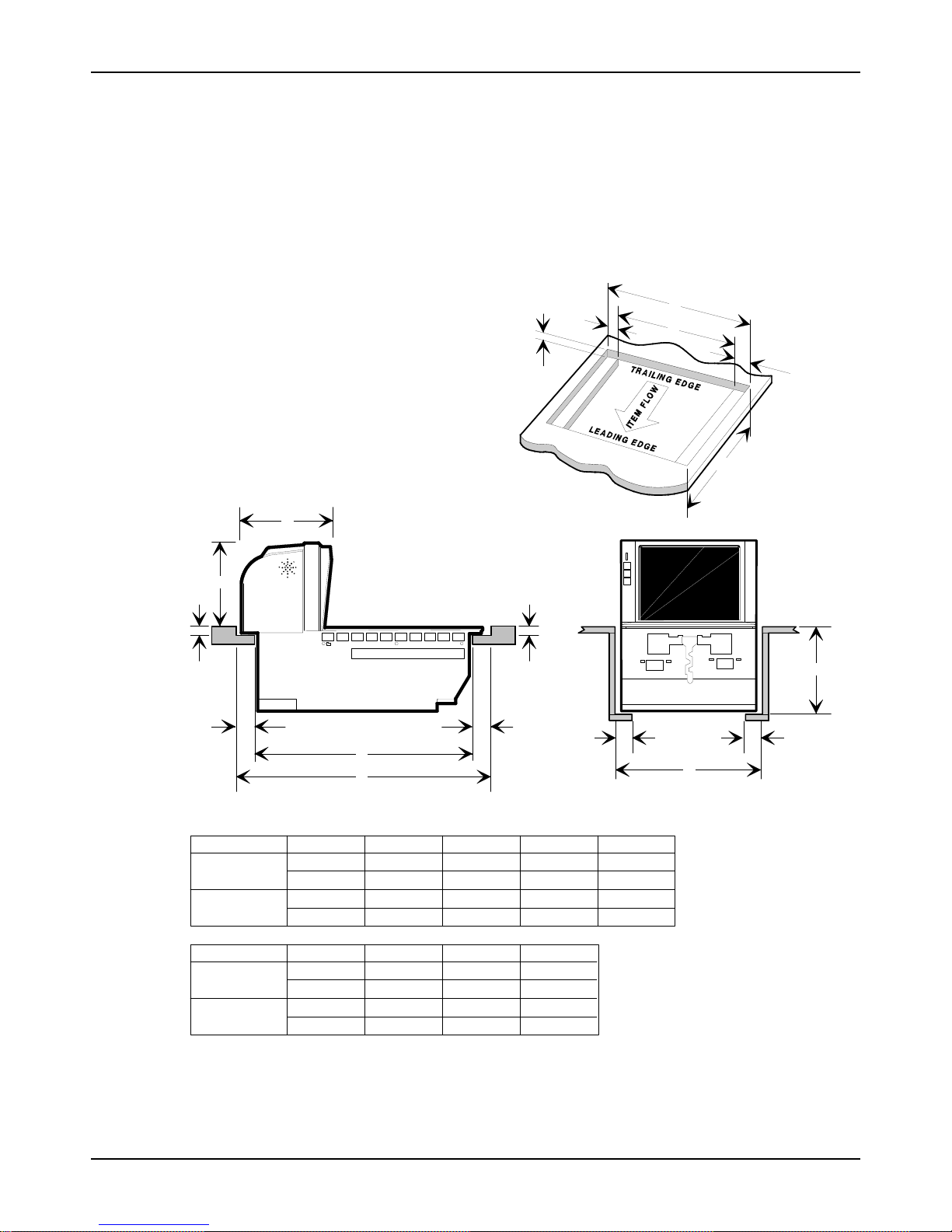
Checkstand Cutout –
RealScan 7875-7000/8000
Step 1 – Verify and Prepare the
Checkstand
I
H
D D
C C
E
B
C
D
*
F
No electronics under RealScan 7875
B
E
C
A
G
F
A
7875-7200
Scanner
7875-8200
Scanner/Scale
7875-7200
Scanner
7875-8200
Scanner/Scale
11 5/8 in.
29.51 cm
12 1/16 in.
30.63 cm
1 3/8 in.
3.49 cm
1 3/8 in.
3.49 cm
06/03 AIP-00342 Release B
8 of 56
ABCD E
20 1/16 in.
50.95 cm
20 1/16 in.
50.95 cm
FG
7 1/8 in.
18.1 cm
7 1/8 in.
18.1 cm
1 3/8 in.
3.49 cm
1 3/8 in.
3.49 cm
HI
7 3/8 in.
18.73 cm
7 1/4 in.
18.42 cm
3/8 in.
0.95 cm
1/2 in.
1.27 cm
7 1/4 in.
18.42 cm
7 1/4 in.
18.42 cm
17 5/16 in.
43.97 cm
17 5/16 in.
43.97 cm
Note:
Note:
*
Recommended shelf to catch
RealScan 7875 if dropped
during installation.
Dimension A for a 7875-7200
includes a spacer along each side
of the unit so that it fits an existing
7870-2000 cutout.
Dimension H includes a
Produce Guard.
20551
NCR RealScan 7875-7000/8000 Installation Guide
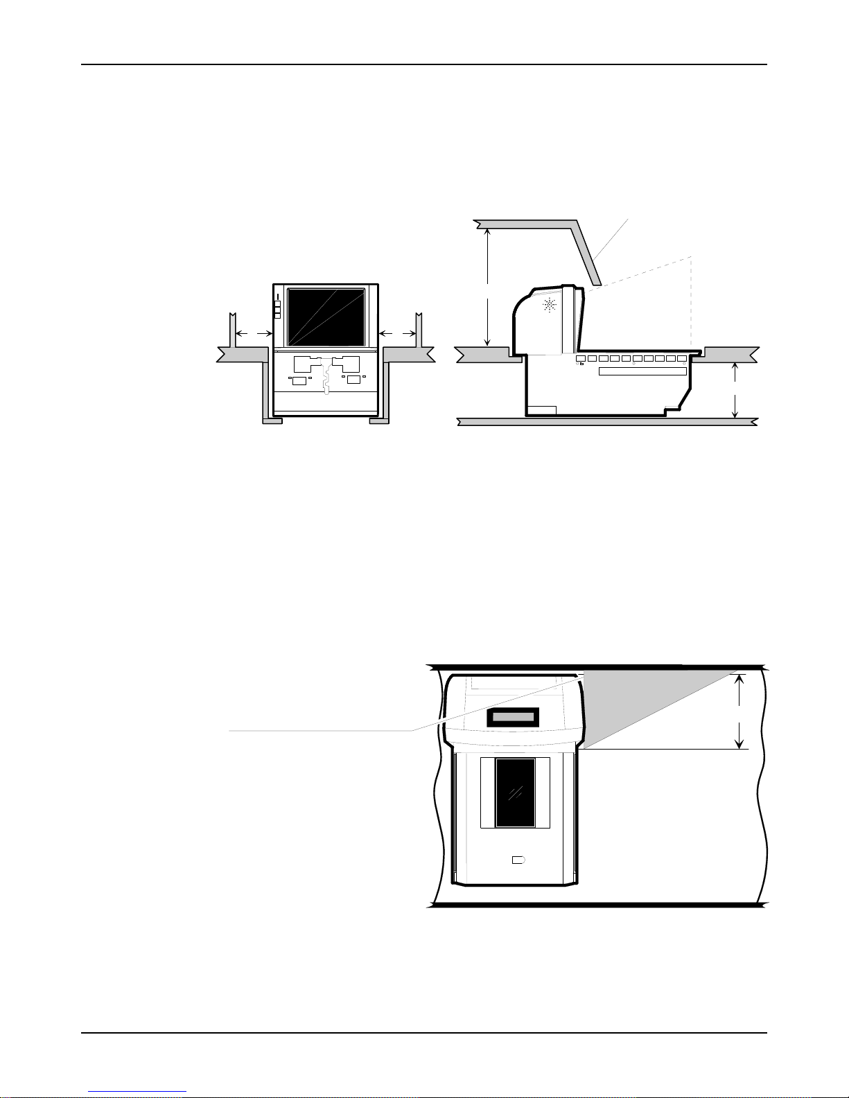
Service Clearance
Mounting surface for keyboard must be
removable for the following.
• Servicing the unit.
• Removing the 7875-8000 Produce Guard.
• Replacing the vertical window.
B
Item Flow Area
A A
C
Item Diverter
A = 20.3 cm (8 in.) minimum if checkstand structure is not removable for servicing.
2.5 cm (1 in.) minimum if checkstand structure is removable for servicing.
B = 35.6 cm (14 in.) minimum if checkstand structure is not removable for servicing.
17.8 cm (7 in.) minimum if checkstand structure is removable for servicing.
C = 18.1 cm (7 1/8 in.) minimum clearance to closest checkstand panel.
The NCR 7875-7000/8000 must not be supported by a bottom panel.
RealScan 7875-8000 units with a Produce Guard must have enough clearance to remove
Note:
the Produce Guard for cleaning. The dimensions given here satisfy these requirements.
Item Diverter
(Must be removable to service
Scanner/Scale in checkstand)
20784
7.25 in. (18.4 cm)
Note: The Item Diverter is not used in most self-checkout installations.
AIP-00342 Release B 06/03
14957
9 of 56

NCR RealScan 7875-7000/8000 Installation Guide
Ventilation Requirements
The RealScan 7875 is designed to operate without an exhaust fan in the checkstand; however,
there must be adequate convection airflow. The ambient temperature inside the checkstand
cannot be higher than 40° C (104° F). Also, the ambient temperature inside the checkstand
cannot be higher than 7° C (12.6° F) above the ambient temperature outside the checkstand. For
example, if the ambient temperature outside the checkstand is 24.4° C (76° F), the ambient
temperature inside the checkstand cannot be greater than 31.4° C (88.6° F). If the checkstand
contains other heat producing equipment, you may need to use forced air to keep the temperature
within the specified range. However, air coming into or leaving the checkstand MUST NOT
enter or exit past the RealScan 7875.
06/03 AIP-00342 Release B
10 of 56
NCR RealScan 7875-7000/8000 Installation Guide
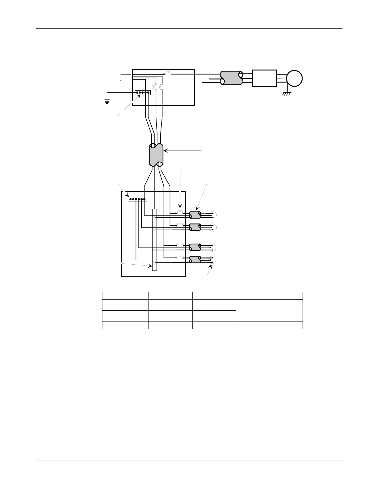
Electrical Wiring to the Checkstand
Input
Voltage
Neutral and
Ground Bus
Isolated/Insulated
Ground Bus
Neutral
Bus
Main Service
L2
Distribution Panel
Panel
L1
L3
Belt Control
N
G
Circuit A: Checkstand
Note:
Isolated Ground Receptacles
Conduit
The electrical wiring must meet all
electrical codes, laws, and regulations.
Feeder wiring and insulated ground from
main service panel to distribution panel
to be run in metal conduit.
Circuit Breakers
NCR circuits should be run in
separate metal Conduits.
NCR circuits must be dedicated to
Note:
NCR equipment or other logically
connected electronic equipment
(modems, DAA, bridges, etc.)
Circuit B: Terminal
Circuit C: Scanner/Scal e
Receptacle should be easily
accessible and near the
Scanner/Scale
Lighting
Misc. Equip.
Checkstand
Frame
Belt
Motor
Installation Type
U.S., Canada, &
Japan
International
European
Note: The RealScan 7875 outlet in the checkstand must be connected to a circuit breaker switch.
This switch must be located close to the operator and is used as the On/Off switch for the
RealScan 7875.
AIP-00342 Release B 06/03
Input Voltage L1, L2 Circuit Breakers
100Vac to 120Vac
220Vac to 240Vac
220Vac
100Vac to 120Vac
220Vac to 240Vac
220Vac
Standard single-pole; value
determined by type of device
branch and by electrical code.
European double-pole.
R0121
11 of 56

NCR RealScan 7875-7000/8000 Installation Guide
Specific Checkstand Modifications
A few checkstands require some modification. Appendices are included for these different types
of checkstands. If modifications are needed, refer to the appendix that matches your installation.
After making any necessary modifications, continue to step 2 on the next page.
• Appendix A – Pan-Oston PO-2
• Appendix B – Pan-Oston PO-3
• Appendix C – Pan-Oston PO-4
Sensormatic Equipment
• Plug the power cord of the Sensormatic ScanMaxTM Pro into an ac outlet not dedicated to
POS equipment. Plug into an unswitched ac outlet with less than 0.5Vac between neutral
and ground. Electrical Primary input: 100-120/200-240Vac, 50-60 Hz ±5%, 1Arms
maximum.
• Do Not connect through generator or Uninterruptible Power Supply (UPS).
• Keep the power cord and antenna cable away from cash drawers and other items whose
operation may pinch or otherwise damage them. Failure to do so can damage equipment or
injure people nearby.
• Do not plug or unplug ANY Sensormatic ScanMax
• If mounting the controller to the sidewall of a counter, its cable connectors cannot face up.
• Deactivator Interacting with Other Devices: Isolate ScanMax Pro controller from neon
signs, motors, computers, cash registers, terminals, or data communications equipment.
Computer monitors, TVs, switching power supplies and neon displays can affect deactivator
operation. Keep the Sensormatic ScanMax
whenever possible.
• Environmental: Operating temperature 0 to 40°C (32° to 104°F) / Non-operating
temperature -40° to 70°C (-40° to 158°F)
TM
Pro Controller cables with power on.
TM
NS Pro Antenna away from these devices
06/03 AIP-00342 Release B
12 of 56
NCR RealScan 7875-7000/8000 Installation Guide
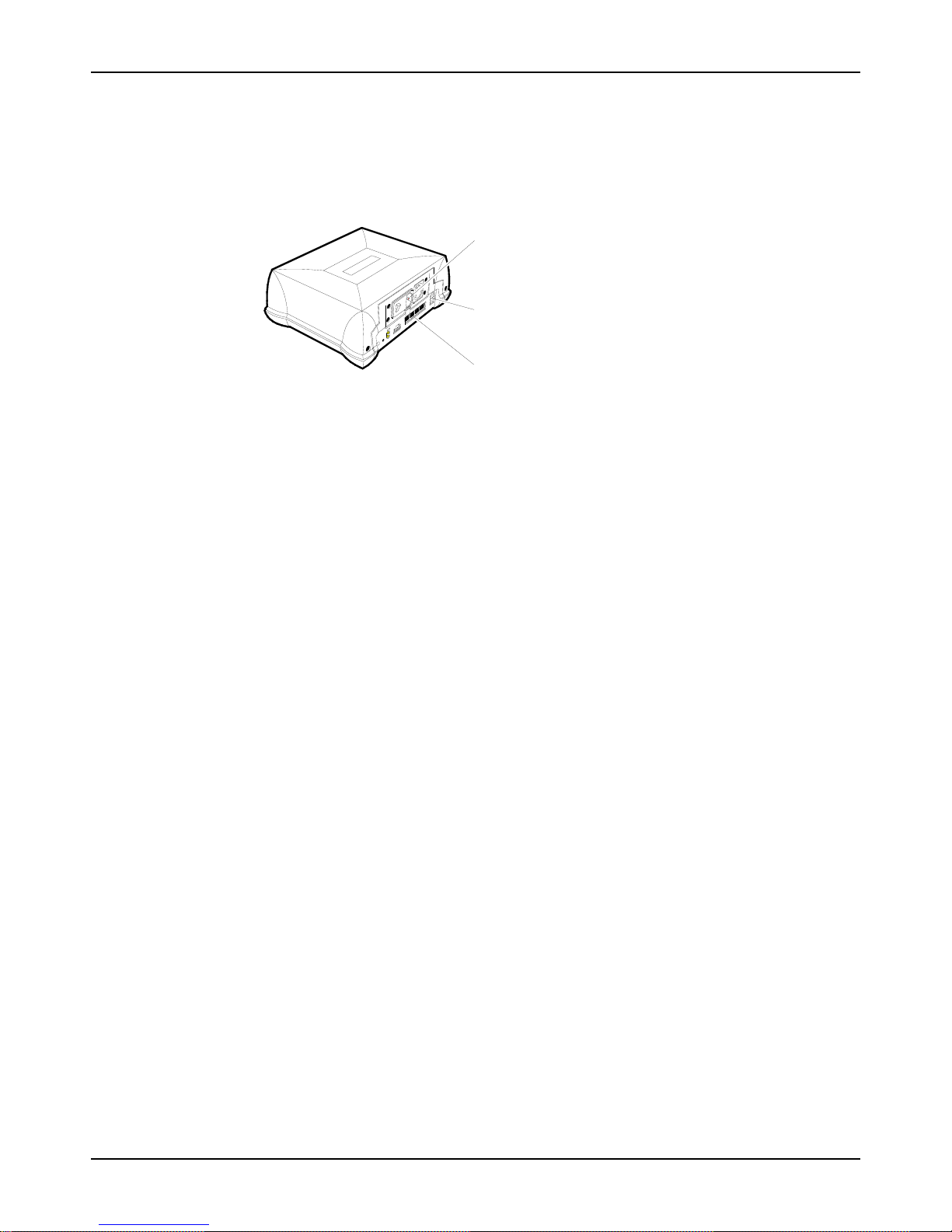
Step 2 – Connect the
Components
AC Power Connector
Antenna Connector
Locate the Sensormatic ScanMax
spilled liquids cannot contact it.
Install Sensormatic Antenna
Note: The Sensormatic ScanMaxTM NS Pro Antenna is very heavy; do not to drop it in the
scanner.
The Sensormatic ScanMax
7875. It should always be placed on the trailing side. If the installation is setup to scan from
right-to-left, put the Sensormatic Antenna on the left side of the scanner as shown in the
illustration.
1. Feed the Sensormatic Antenna Cable through the large hole in the front of the Mounting
Bracket (bucket). This must be the hole on the side where you are installing the antenna.
Note: Depending on the checkstand configuration, you may have to slide the back of the
Antenna under the Produce Guard if one is included. The Antenna must not interfere with
Produce Guard movement.
2. Carefully place the Sensormatic Antenna in position, setting it on the Sub Plate.
3. Route the Sensormatic Antenna Cable down through the slot in the front of the Mounting
Bracket (bucket).
TM
Communications Connector (POS)
TM
Pro Controller inside the checkstand in a position where
NS Pro Antenna can be positioned on either side of the RealScan
20588
AIP-00342 Release B 06/03
13 of 56
NCR RealScan 7875-7000/8000 Installation Guide
Connect Sensormatic Cables
Sensormatic Antenna
Sensormatic Antenna Cable
20574
The Sensormatic Antenna Cable and the Sensormatic Communications Cable go between the
RealScan 7875 and the ScanMax
TM
Pro Controller. Be sure to route these cables through the
cutout in the checkstand.
1. Connect the Sensormatic Antenna Cable to the Antenna connector on the ScanMax
TM
Pro
Controller.
2. Connect one end of Sensormatic Communications Cable to one of the RS-232 Peripheral
Ports on the RealScan 7875 and the other end to the POS connector on the ScanMax
TM
Pro
Controller.
RealScan 7875
Sensormatic
Antenna
Cable
PROGSTATUS
Sensormatic
Communications Cable
AC
Power
Cord
MNS
BCAN I/O POS SERVICE REMOTE ANTENNAEXPANSIONBR
ScanMax™
Pro Controller
20592
06/03 AIP-00342 Release B
14 of 56
NCR RealScan 7875-7000/8000 Installation Guide
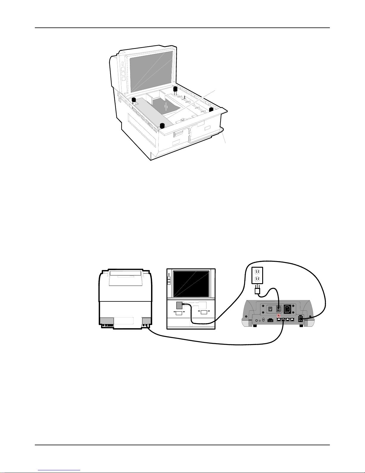
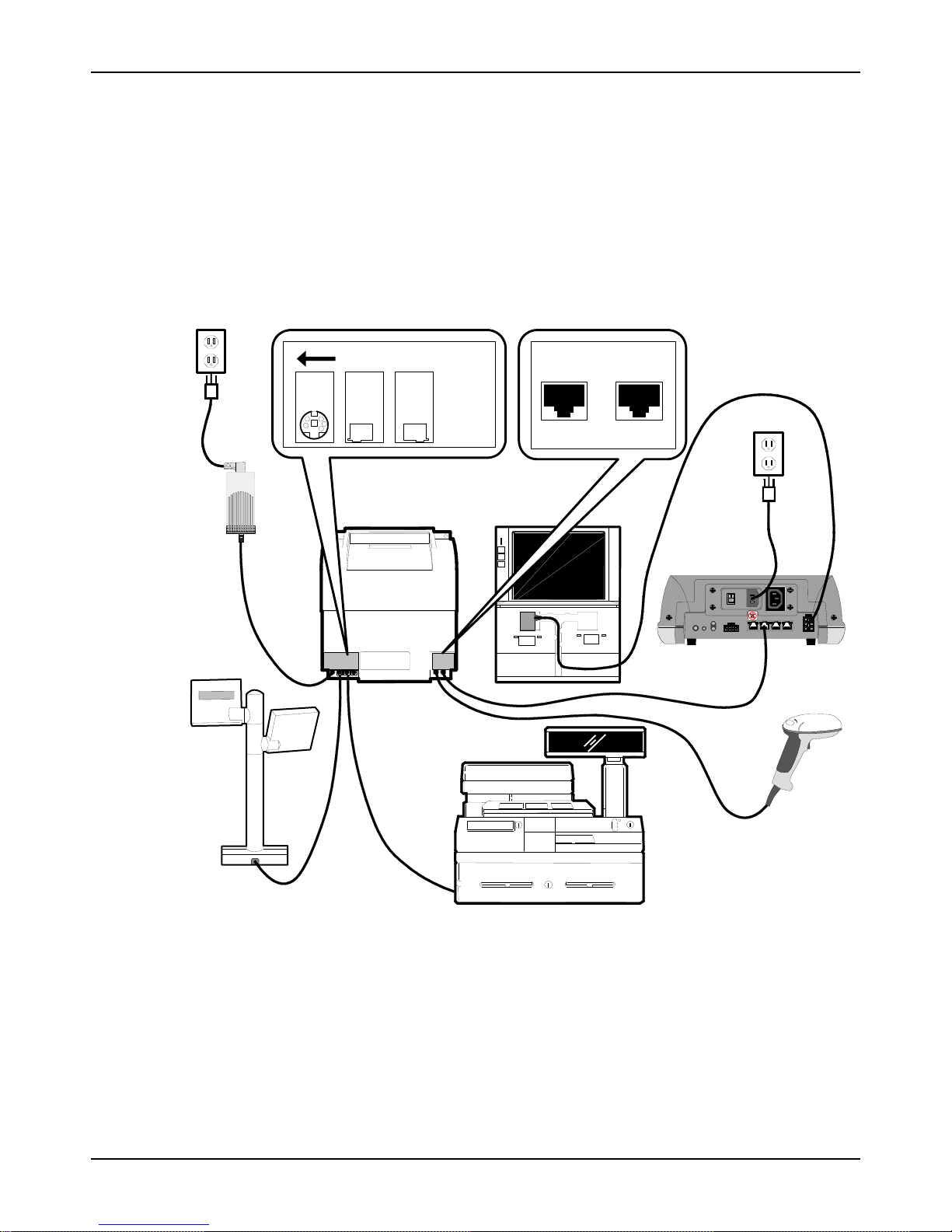
Connect Remaining Components
Locate the NCR RealScan 7875 Power Supply in position in the checkstand where spilled liquid
cannot contact it. The system configuration may also include a Remote Display and an RS-232
peripheral such as a hand-held scanner. The following illustration shows how all cables are
connected. Be sure to route these cables properly through the checkstand. After all cables are
connected, plug in the NCR RealScan 7875 and the Sensormatic ScanMax
Power Cords to supply power to the units.
TM
Pro Controller
AC
Power
Cord
Power
Supply
DC
Power
Cable
Remote
Display
Check switch settings
C
R
E
D
W
O
P
Y
E
T
A
X
L
A
O
P
M
M
S
E
I
A
R
D
5
V
5
Interface
Cable
R
E
N
N
A
C
S
RealScan 7875
DUAL PERIPHERAL PORTS
PORT 1 PORT 2
Sensormatic
Communications Cable
Host
Terminal
Sensormatic
Antenna
Cable
MNS
PROGSTATUS
AC
Power
Cord
BCAN I/O POS SERVICE REMOTE ANTENNAEXPANSIONBR
Sensormatic
ScanMax™
Pro Controller
RS-232
Peripheral
AIP-00342 Release B 06/03
20553
15 of 56
NCR RealScan 7875-7000/8000 Installation Guide
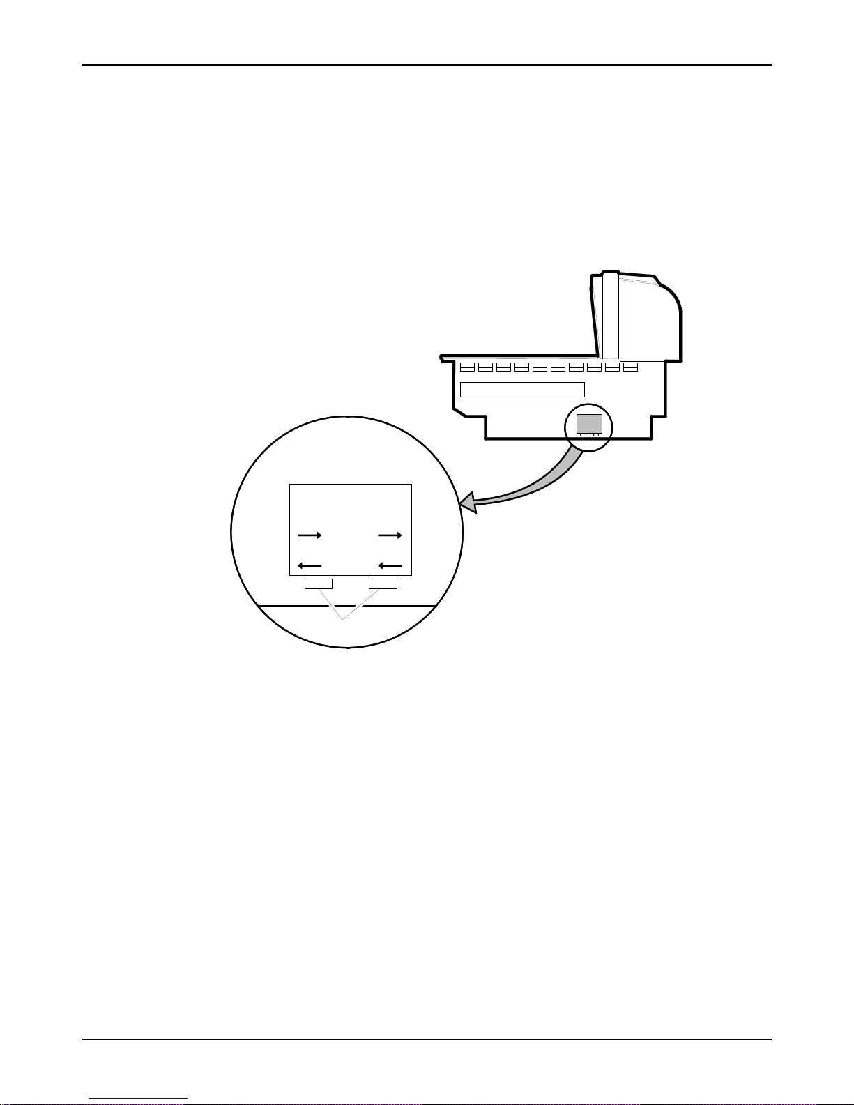
Set the Communications Protocol Switch
Before setting the RealScan 7875 into the cutout in the checkstand, verify that the
Communications Protocol Switch is properly set. Single cable units have one switch, dual cable
units have two. The switches are located on the Interface Board and you can access them
through holes in the side of the unit. For RS-232 communications, both switches must be toward
the front (operator side) of the unit. For all other communication protocols, both switches must
be toward the back (customer side) of the unit.
AUX PO RT/
DATACHKR
DATACHKR OCIA/IBM
Make sure power is
off before changing
switch setting
RS-232 RS-232
SCANNER
Switches
20789
06/03 AIP-00342 Release B
16 of 56

NCR RealScan 7875-7000/8000 Installation Guide
Step 3 – Sensormatic
Deactivation Setup
Power up the System
Note: Refer to the Sensormatic ScanMax™ Pro Controller documentation for additional
information about setting up the controller.
1. Turn on the NCR RealScan 7875. When the RealScan 7875 is first turned on, all the
Sensormatic parameters should be at their default settings.
• RealScan 7875 Scan tone delay until deactivation = Enabled
• RealScan 7875 Deactivation button = Disabled
• RealScan 7875 Clicking = Enabled
The RealScan 7875 should give the voice message EAS Offline if the Sensormatic
ScanMax
2. Turn on the Sensormatic ScanMax
factory with default settings for proper operation.
3. After the RealScan 7875 and the Sensormatic ScanMax
for about 15 seconds, the RealScan 7875 should give the voice message EAS Online.
Note: Voice message EAS Online must be given before you can continue. If voice message
EAS Online is not given, turn off the power to all components. Check all cable connections
then repeat this procedure starting at step 1. If voice message EAS Online is still not given
and the Red Status Indicator is flashing rapidly, scan the Reset programming tag. If the
status given is still EAS Offline, follow instructions on the Sensormatic Card – Before You
Call About… The problem may be a bad Antenna cable.
4. Position a Hard Tag over the top of the RealScan 7875. As you move the Hard Tag, the
RealScan 7875 should start clicking when the tag moves within 4 inches of the center of the
Top Plate. If the clicking sound is not generated, scan the Reset programming tag, then go
to step 3. If the second attempt fails, call for help. Refer to Obtaining Technical Assistance.
TM
Pro Controller is still turned off. Also, the Red Status Indicator flashes rapidly.
TM
Pro Controller. This system is programmed at the
TM
Pro Controller have both been on
AIP-00342 Release B 06/03
17 of 56
 Loading...