

NCR RealScan 7872 Owners Manual

RealScan 7872
Installation/Owner Guide
497-0415291
Release F
August 30, 2004
Information Products
RSD-Atlanta

NCR RealScan 7872 Installation/Owner Guide
The product described in this book is a licensed product of NCR Corporation.
NCR is a registered trademark of NCR Corporation.
It is the policy of NCR Corporation (NCR) to improve products as new technology,
components, software, and firmware become available. NCR, therefore, reserves the
right to change specifications without prior notice.
All features, functions, and operations described herein may not be marketed by NCR in
all parts of the world. In some instances, photographs are of equipment prototypes.
Therefore, before using this document, consult with your NCR representative or NCR
office for information that is applicable and current.
To maintain the quality of our publications, we need your comments on the accuracy,
clarity, organization, and value of this book.
Address correspondence to:
Manager, Information Products
NCR Corporation
2651 Satellite Blvd.
Duluth, GA 30096
Copyright © 2000 ñ 2004
By NCR Corporation
Dayton, Ohio U.S.A.
All Rights Reserved
08/04 497-0415291 Release F2 of 44

Audience
References
NCR RealScan 7872 Installation/Owner Guide
Preface
This book is written for hardware installer/service personnel, system integrators, and
field engineers.
•
NCR RealScan 7872 User Guide
(B005-0000-1179)
•
NCR RealScan 7872 Repair Guide
(B005-0000-1180)
497-0415291 Release F 08/04 3 of 44

NCR RealScan 7872 Installation/Owner Guide
Preface........................................................................................................................................... 3
Audience.................................................................................................................................. 3
References................................................................................................................................ 3
Table of Contents......................................................................................................................... 4
Revision Record........................................................................................................................... 5
Installing the RealScan 7872....................................................................................................... 6
Step 1 Verify Checkstand Preparation................................................................................ 7
Step 2 Connect the Cables .................................................................................................. 14
Step 3 Install RealScan 7872 in Checkstand ..................................................................... 17
Step 4 Calibrate the Scale.................................................................................................... 19
Step 5 Check the Scanner Operation................................................................................. 24
Operating the Scanner .............................................................................................................. 27
Operating the Scale ................................................................................................................... 28
Table of Contents
Cleaning the RealScan 7872 ..................................................................................................... 29
Correcting Scanner Problems .................................................................................................. 30
Correcting Scale Problems .......................................................................................................31
Isolating Bizerba Scale Problems............................................................................................. 32
Setting the Communication Protocol...................................................................................... 33
Good Read Tone........................................................................................................................ 34
Programming Worksheets ....................................................................................................... 35
10 Communications Protocol .............................................................................................. 35
11 Good Read Tone .............................................................................................................. 35
12 Timers................................................................................................................................ 36
13 Bar Codes - 1 .................................................................................................................... 36
14 Bar Codes ñ 2.................................................................................................................... 37
15 Bar Codes - 3 .................................................................................................................... 38
17 Bar Codes - 4 .................................................................................................................... 38
18 Bar Codes ñ 5.................................................................................................................... 39
16 Label Identifiers............................................................................................................... 39
20 RS-232 Parameters ñ 1..................................................................................................... 40
21 RS-232 Parameters ñ 2..................................................................................................... 40
22 RS-232 Prefix Byte ...........................................................................................................41
23 RS-232 Terminator Byte.................................................................................................. 41
24 RS-232 Communications Options.................................................................................. 41
30 Scale Parameters.............................................................................................................. 42
32 Miscellaneous Parameters.............................................................................................. 42
ASCII Code Chart................................................................................................................. 42
08/04 497-0415291 Release F4 of 44

NCR RealScan 7872 Installation/Owner Guide
Revision Record
Issue Date Remarks
A June 2000 First Issue
B Aug 2000 Update to diagrams and worksheets
C 05/08/01 Updated checkstand cutout dimensions
D 02/06/03 Added USB Connection and other miscellaneous information.
E 03/22/04 Updated to Super ASIC configuration
F 08/30/04 Added new model number
497-0415291 Release F 08/04 5 of 44
NCR RealScan 7872 Installation/Owner Guide
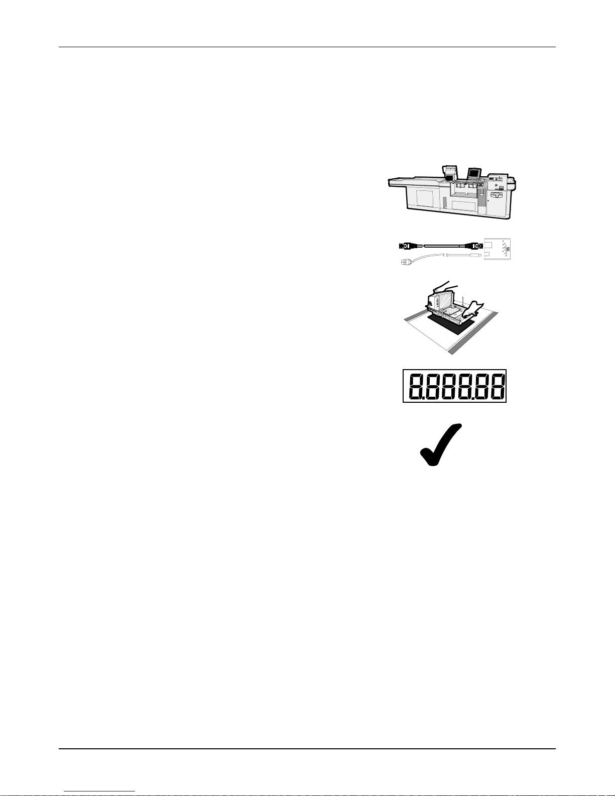
Installing the RealScan 7872 consists of five main steps. Depending on the installation,
other information is sometimes needed. It is recommended that you follow the
installation steps in the following diagram.
Installing the RealScan 7872
1
2
3
4
5
Preparation
Connect
Install
Calibrate
Verify
18265
08/04 497-0415291 Release F6 of 44
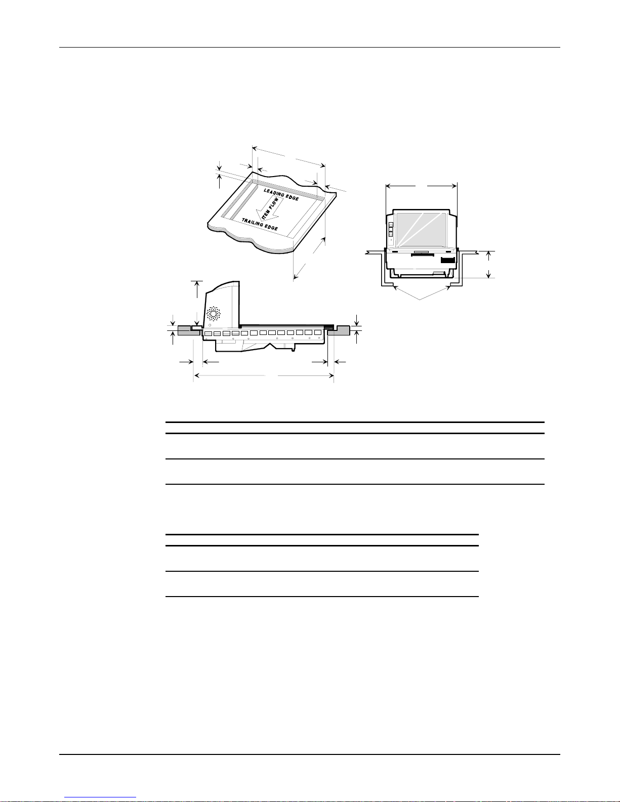
Step 1 Verify Checkstand Preparation
Checkstand Cutout: RealScan 7872 ñ 12xx/22xx
NCR RealScan 7872 Installation/Owner Guide
I
H
C
I
D
G
H
F
I
A
E
Shelf is recommended to catch RealScan 7872
if dropped during installation. It may also
include a drip pan for spilled liquids.
The RealScan 7872 must NOT be supported
by this shelf.
D
B
Scanner Unit Actual Dimensions
MODELABCDE
12xx 29.21 cm
11 1/2 in.
22xx 30.33 cm
11 15/16 in.
50.80 cm
20 in.
50.80 cm
20 in.
16.15 cm
6 3/8 in.
16.15 cm
6 3/8 in.
3.33 cm
1 5/16 in.
3.33 cm
1 5/16 in.
8.89 cm
3 1/2 in.
8.89 cm
3 1/2 in.
17951
Cutout Dimensions
MODEL F G H I
12xx 29.51 cm
22xx 30.48 cm
497-0415291 Release F 08/04 7 of 44
11 5/8 in.
12 in.
50.95 cm
20 1/16 in.
50.95 cm
20 1/16 in.
3.49 cm
1 3/8 in.
3.49 cm
1 3/8 in.
0.95 cm
3/8 in.
1.27 cm
1/2 in.

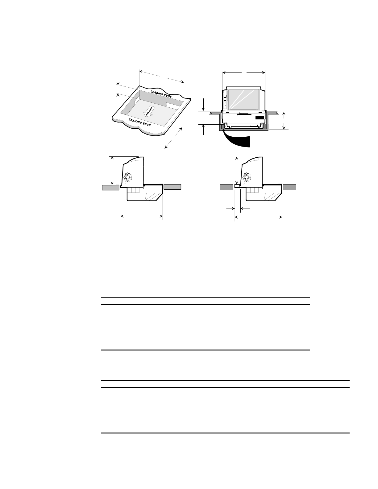
NCR RealScan 7872 Installation/Owner Guide
Checkstand Cutout: RealScan 7872 ñ 53xx/52xx
F
G
A
E
C
D
2.5 cm (1.0 in.) side supports are
optional instead of shelf
B
Scanner Unit Actual Dimensions
MODELABCD
53xx 29.21 cm
11 1/2 in.
39.88 cm
15 11/16 in.
16.15 cm
6 3/8 in.
8.89 cm
3 1/2 in.
Cutout Dimensions
MODEL E F G
53xx 29.36 cm
11 9/16 in.
40.03 cm
15 3/4 in.
5.72 cm
2 1/4 in.
18151
08/04 497-0415291 Release F8 of 44
Checkstand Cutout: RealScan 7872 ñ 03xx/05xx
y
y
NCR RealScan 7872 Installation/Owner Guide
H
C
Standard Size
G
I
F
A
D
2.5 cm (1.0 in.) side supports are
optional instead of shelf
C
E
B
B
RealScan 7870-3000 & PSC 381 Size
Note:
The RealScan 7872-03xx/05xx is
supported b
Do not support it b
side supports or a shelf.
the Rear Extender.
17952
Scanner Unit Actual Dimensions
MODELABCD
03xx/05xx 29.21 cm
11 1/2 in.
Fits 7870-3000 29.21 cm
11 1/2 in.
Fits PSC 381 29.21 cm
11 1/2 in.
29.46 cm
11 9/16 in.
34.36 cm
13 1/2 in.
35.25 cm
13 7/8 in.
16.15 cm
6 3/8 in.
16.15 cm
6 3/8 in.
16.15 cm
6 3/8 in.
8.89 cm
3 1/2 in.
12.70 cm
5 in.
10.16 cm
4 in.
Cutout Dimensions
MODEL E F G H I
03xx/05xx N/A
N/A
Fits 7870-3000 4.90 cm
1 15/16 in.
Fits PSC 381 5.79 cm
2 1/4 in.
497-0415291 Release F 08/04 9 of 44
29.36 cm
11 9/16 in.
29.36 cm
11 9/16 in.
29.36 cm
11 9/16 in.
29.62 cm
11 5/8 in.
34.52 cm
13 5/8 in.
35.41 cm
13 15/16 in.
8.89 cm
3 1/2 in.
12.70 cm
5 in.
10.16 cm
4 in.
5.72 cm
2 1/4 in.
5.72 cm
2 1/4 in.
5.72 cm
2 1/4 in.
NCR RealScan 7872 Installation/Owner Guide
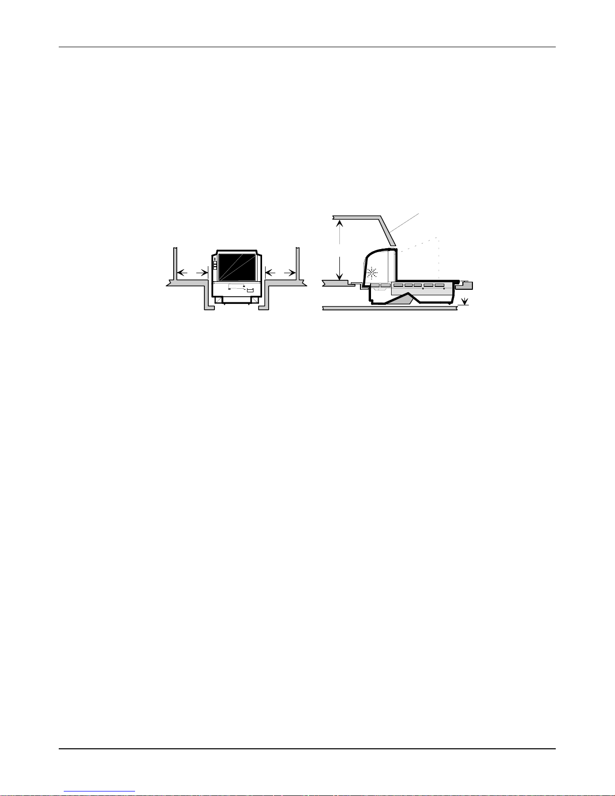
Drip Pan Installation
When the RealScan 7872 is used in a sit down environment, install a drip pan below the
scanner/scale to divert any spilled liquids or debris away from the operator.
Service Clearance
Mounting surface for
keyboard must be
removable for servicing
B
A
A = 8.0 in. (20.3 cm) minimum if checkstand structure is not removable for servicing.
1.0 in. (2.5 cm) minimum if checkstand structure is removable for servicing.
B = 14.0 in. (35.6 cm) minimum if checkstand structure is not removable for servicing.
7.0 in. (17.8 cm) minimum if checkstand structure is removable for servicing.
C = 3.8in. (9.5 cm) minimum clearance to closest checkstand panel.
A
C
18152
08/04 497-0415291 Release F10 of 44
Item Diverter
NCR RealScan 7872 Installation/Owner Guide
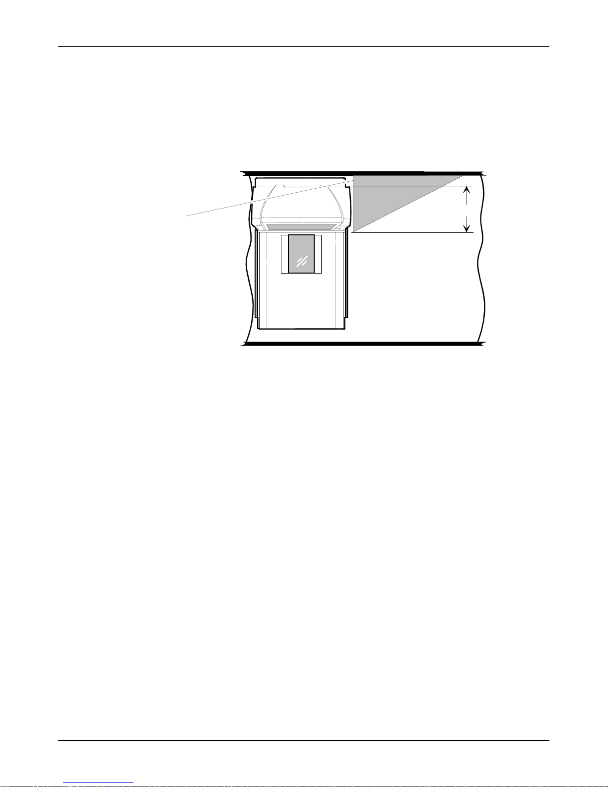
An installed item diverter must extend º inch beyond the scan window to allow items
to clear the tower assembly and move easily in front of the scan windows. The tower is
13.3 cm wide, however the item diverter may need to be wider depending on the model.
See the sections Checkstand Cutout for more dimensions.
13.3 cm (5 º in.)
Item Diverter
Ventilation Requirements
The RealScan 7872 is designed to operate without an exhaust fan in the checkstand;
however, there must be adequate convection airflow. The ambient temperature inside
the checkstand cannot be higher than 40∞ C (104∞ F). Also, the ambient temperature
inside the checkstand cannot be higher than 7∞ C (12.6∞ F) above the ambient
temperature outside the checkstand. For example, if the ambient temperature outside
the checkstand is 24.4∞ C (76∞ F), the ambient temperature inside the checkstand cannot
be greater than 31.4∞ C (88.6∞ F). If the checkstand contains other heat producing
equipment, you may need to use forced air to keep the temperature within the specified
range. However, air coming into or leaving the checkstand MUST NOT enter or exit
past the RealScan 7872.
18085
497-0415291 Release F 08/04 11 of 44
NCR RealScan 7872 Installation/Owner Guide
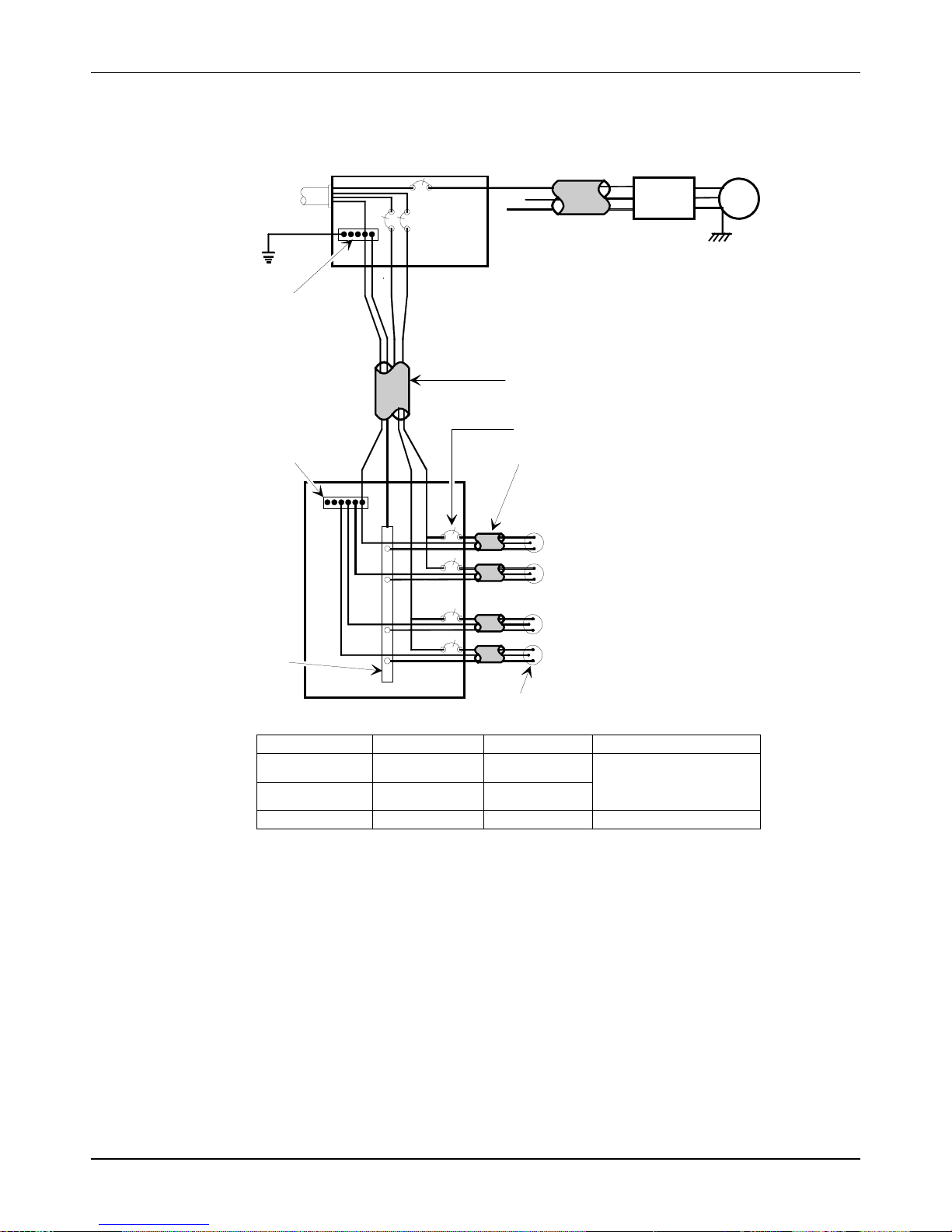
Electrical Wiring to the Checkstand
Input
Voltage
Neutral and
Ground Bus
Isolated/Insulated
Ground Bus
Neutral
Bus
Main Service
L2
Distribution Panel
Panel
L1
L3
Belt Control
N
G
Circuit A: Checkstand
Note:
Isolated Ground Receptacles
Conduit
The electrical wiring must meet all
electrical codes, laws, and regulations.
Feeder wiring and insulated ground from
main service panel to distribution panel
to be run in metal conduit.
Circuit Breakers
NCR circuits should be run in
separate metal Conduits.
NCR circuits must be dedicated to
Note:
NCR equipment or other logically
connected electronic equipment
(modems, DAA, bridges, etc.)
Circuit B: Terminal
Circuit C: Scanner/Scale
Receptacle should be easily
accessible and near the
Scanner/Scale
Lighting
Misc. Equip.
Checkstand
Frame
Belt
Motor
Installation Type
U.S., Canada, &
Japan
International
European
Input Voltage L1, L2 Circuit Breakers
100Vac to 120Vac
220Vac to 240Vac
220Vac
100Vac to 120Vac
220Vac to 240Vac
220Vac
Standard single-pole; value
determined by type of device
branch and by electrical code.
European double-pole.
The RealScan 7872 outlet in the checkstand must be connected to a circuit breaker
switch. This switch must be located close to the operator and is used as the On/Off
switch for the RealScan 7872.
08/04 497-0415291 Release F12 of 44
R0121

Hole Requirements for Cables
When you run the various cables through the checkstand, you might have to drill holes
in some of the panels. The holes must be large enough for the connector on one end of
the cable to pass through. You must also ensure that there are no sharp edges to cut the
cable. The following table gives the minimum hole size for each of the RealScan 7872
cables.
Cable Cable Length Minimum Hole Size
Power Cord ñ Outlet to
Power Supply
Power Cord ñ Power
Supply to RealScan 7872
Interface Cable 8.0 meters (26.24 feet) 1.90 centimeters (3/4 inch)
Remote Display Cable 8.0 meters (26.24 feet) 1.90 centimeters (3/4 inch)
NCR RealScan 7872 Installation/Owner Guide
3.05 meters (10 feet) 3.18 centimeters (3/4 inch)
1.22 meters (4 feet) 1.52 centimeters (1/2 inch)
4.0 meters (12.12 feet) 1.90 centimeters (3/4 inch)
4.0 meters (12.12 feet) 1.90 centimeters (3/4 inch)
497-0415291 Release F 08/04 13 of 44
NCR RealScan 7872 Installation/Owner Guide
Step 2 Connect the Cables
1.
Verify that the RealScan 7872 power receptacle switch is off. Plug the power cord
into the RealScan 7872 power receptacle. Pass the power cable from the power
supply through the checkstand opening.
2. Connect the communications interface cables to the host terminal. Refer to the
terminal documentation for instructions on connecting the interface cables.
Note: Some terminals may require a trained service technician to open the terminal
and connect the interface cables.
3. Pass the interface cable through the checkstand opening (See previous section
regarding Hole Requirements for Cables).
4.
If you are installing an NCR 7825 Remote Display, pass the cable from the display,
through the checkstand, and through the checkstand opening where the RealScan
7872 is going.
5.
If you are installing an RS-232 peripheral device, pass its interface cable through the
checkstand opening as needed.
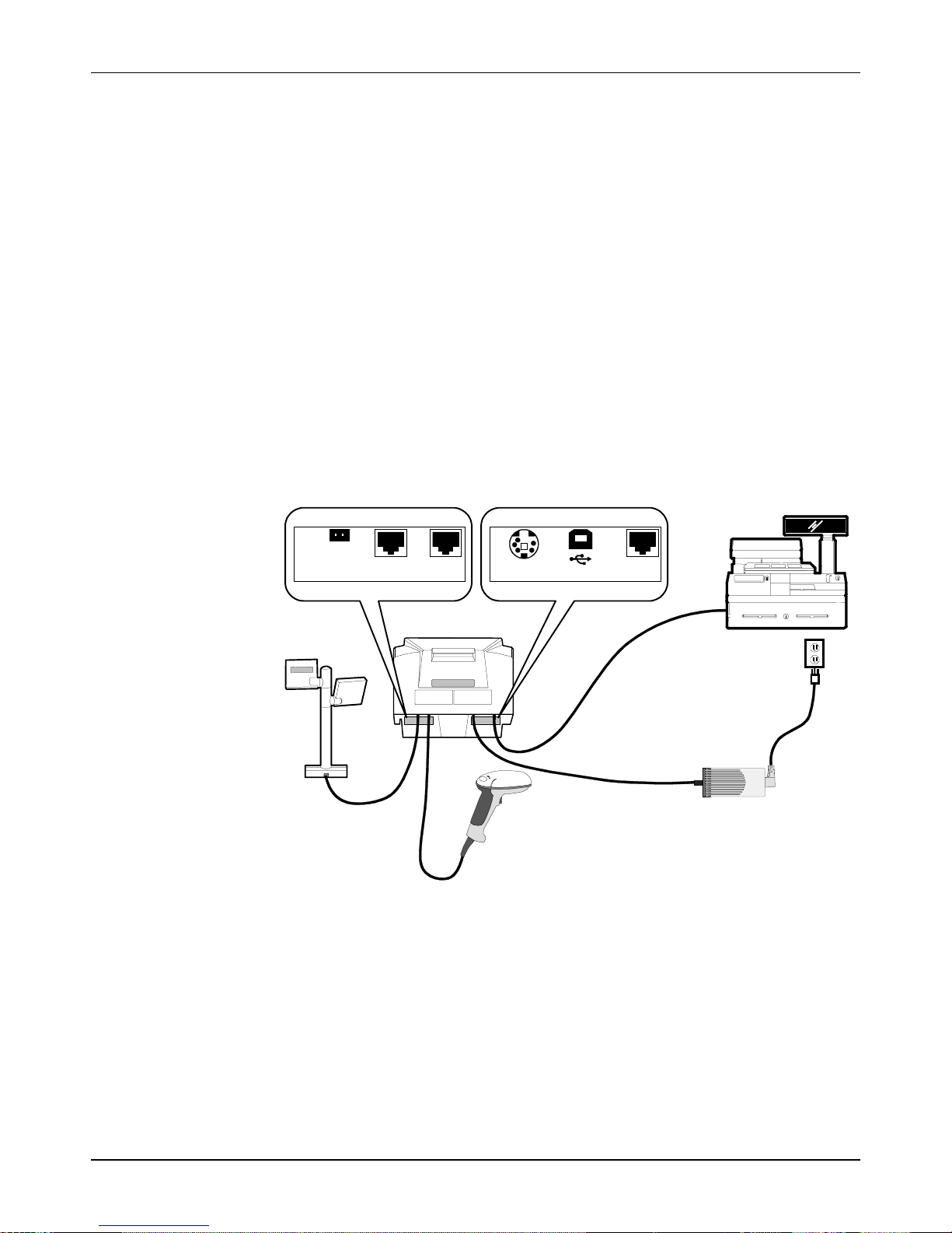
6. Connect all cables to the RealScan 7872 according to the following illustration.
EAS
INTERLOCK
REMOTE DISPLAY
5V 5A MAX
PORT 1
POWER
DC
USB
SCANNER
21476
Note: If you are using a USB cable to connect the RealScan 7872 to the host terminal,
connect the USB cable to the USB connector rather than the Scanner connector on
the back of the RealScan 7872.
08/04 497-0415291 Release F14 of 44
 Loading...