

NCR Realscan 7837 User Manual

NCR Realscan 7837
High-Perfo rmance Scanners
User’s Guide
™
497-0427357
Issue A

Disclaimer
The product described in this book is a licensed product of NCR Corporation.
NCR RealScan is either a registered trademark or a trademark of NCR
Corporation in the United States and/or other countries.
It is the policy of NCR Corporation (NCR) to improve products as new
technology, components, software, and firmware become available. NCR,
therefore, reserves the right to change specifications without prior notice. All
features, functions, and operations described herein may not be marketed by
NCR in all parts of the world. In some instances, photographs are of equipment
prototypes. Therefore, before using this document, consult with your NCR
representativ e or NCR office for inf ormation that is applicable and curren t.
To maintain the quality of our publications, we need your comments on the
accuracy, clarity, organization, and value of this book.
Address correspondence to:
Manager, Information Products
NCR Corporation
2651 Satellite Blvd.
Duluth, GA 30096
Copyright 2002
By NCR Corporation
Dayton, Ohio U.S.A.
All rights reserved

Statement of Agency Compliance
This devic e com pl ies w i th part 15 of the FCC R ul es . Op era tion is subject to the
following two conditions: (1) thi s device ma y not cause harm ful interferenc e, and
(2) this device must accept any interference re ceived, inc luding interfe rence that
may cause undesired operation.
FCC Class B Compliance Statement
This equipment has been tested and found to comply with the limits for a Class
B digital de vice pu rsuant to part 15 of th e FCC Rul es. The se lim its are designed
to provide reasonable protection against harmful interference in a residential
installation. This equipment generates, uses, and can radiate radio frequency
energy and, if not installed and used in accordance with the instructions, may
cause harmful interference to radio communications. However, there is no
guarantee that interference will not occur in a particular installation. If this
equipment does cause harmful interference to radio or television reception,
which can be determined by turning the equipment off and on, the user is
encouraged to try to correct the interference by one or more of the following
measures:
• Reorient or relocate the receiving antenna.
• Increase the separation between the equipment and receiver.
• Connect the equipment into an outlet on a circuit different from that to
which the receiver is connected.
• Consult the dealer or an experienced radio or television technician for
help.
Caution: Any changes or modifications made to this device that are not
expressly approved by NCR may void the user’s authority to operate the
equipment.
Note: To maintain compliance with FCC Rules and Regulations, cables
connected to this device must be shielded cables, in which the cable shield
wire(s) have been grounded (tied) to the connector shell.
Canadian Notice
This equipm ent do es no t ex c eed th e C la ss B limits for radio n ois e e mi ss io ns as
described in the Radio I nte rfere nce Re gulations of the Ca nadian Department of
Communications.
Le present appar eil num erique n’emet pas de bruits radioe lectriq ues depas sant
les limites applicables aux appareils numeriques de la c las se B pr es cri tes dan s
le Reglement sur le brouillage radioelectrique edicte par le ministere des
Communications du Canada.

The CE mark on the product indicates that the system has been
tested to and conform s with th e pro vis io ns note d with in th e 89/336/
EEC Electromagnetic Compatibility Directive and the 73/23/EEC
Low Voltage Directive.
NCR shall not be liable for use of our product with equipment (i.e., power
supplies, personal computers, etc.) that is not CE marked and does not comply
with the Low Voltage Directive.
UL and cUL Statement
UL listed UL1950 and CSA 22.2 No.950. cUL listed UL1950 and CSA 22.2 No
950.
LED Safety Statement
This device ha s been tested in accordan ce with EN60825-1 LED safety, and has
been certified to be under the limits of a Class 1 LED device.
TÜV Statement
TÜV or GS marked to EN60950 and EN60825-1.
C-TIC Statement
Conforms to AS/NZS N10410.
Patents
The NCR Real Scan 7837 Hig h-Performance Sca nner is cov ered by one or m ore
of the following U.S. Patents: 5,831,254; 5,900,613; 5,932,862; 5,942,741;
5,965,863; 6,119,939; 6,164,544; 6,254,003 B1; 6,275,388 B1, 6,371,374 B1.
Other U.S. and foreign patents pending.

Table of Contents
Chapter 1 - Getting Started
About This Manual............................................................... 1-1
Unpacking the Scanner......................................................... 1-2
RealScan 7837 High-Perfo rmanc e Scann er Ide nti fi cation... 1-3
Connecting the Scanner When Powered by Host
(Keyboard Wedge)............................................................. 1-4
Plug and Play........................................................................ 1-5
IBM 4683 Ports 5B, 9B, and 17 Interface............................ 1-7
USB Interface....................................................................... 1-8
USB Converter...................................................................... 1-9
OCIA Interface ................................ ................................... 1-10
NCR OCIA Short Format (8 Bit) Interface ........................ 1-10
NCR OCIA Long Format (9 Bit) Interface......................... 1-11
Nixdorf OCIA Interface...................................................... 1-11
Serial Wedge....................................................................... 1-12
Chapter 2 - Terminal Interfaces
Keyboard Wedge Connection............................................... 2-1
Terminal ID .......................................................................... 2-2
Supported Terminals............................................................. 2-3
Keyboard Country ................................................................ 2-5
Keyboard Style..................................................................... 2-6
Keyboard Modifiers.............................................................. 2-7
Serial Port Connection.......................................................... 2-9
Baud Rate..................................................................... 2-10
RS-232 Word Length: Data Bits, Stop Bits, and Parity2-11
RS-232 Handshaking .................................. ................. 2-13
Wand Emulation Connection....................................... 2-14
Wand Emulation Transmission Rate............................ 2-15
Wand Emulation Polarity............................................. 2-15
Wand Emulation Idle................................................... 2-16
i

PDF417 Wand Emulation...................................................2-16
Data Block Size............................................................2-16
Delay Between Blocks..................................................2-17
Overall Checksum........................................................2-17
Chapter 3 - Output
Scan Rate...............................................................................3-1
Beeper Volume......................................................................3-1
Beeper Tone..........................................................................3-2
Scan Voting...........................................................................3-2
Reduce Quiet Zone................................................................3-2
Reread Delay.........................................................................3-3
Good Read Delay..................................................................3-4
Trigger Mode .......................................................... ..............3-4
Chapter 4 - Data Editing
Prefix/Suffix Overview.........................................................4-1
To Add a Prefix or Suffix:..............................................4-2
To Clear One or All Prefixes or Suffixes:......................4-3
To Add a Carriage Return Suffix to all Symbologies .. ..4-3
Prefix Selections.............................................................4-4
Suffix Selections.............................................................4-4
Symbology Chart ..................................................................4-5
Decimal to Hex to ASCII Conversion Chart.........................4-6
Function Code Transmit.................................................4-7
Intercharacter, Interfunction, and Intermessage Delays........4-7
Intercharacter Delay .......................................................4-7
User Specified Intercharacter Delay...............................4-8
Interfunction Delay.........................................................4-9
Intermessage Delay.........................................................4-9
ii

Chapter 5 - Data Formatting
Data Format Editor Introduction...........................................5-1
To Add a Data Format.................................................... 5-1
Other Programming Selections.......................................5-2
Data Format Editor Commands......................................5-2
Data Format Editor .........................................................5-4
Data Formatter................................................................5-5
Alternate Data Formats...................................................5-5
Chapter 6 - Secondary Interface
Secondary Code 39 Wand Emulation ...................................6-1
Secondary RS-232 Connection .............................................6-1
Secondary Non Decoded Output Laser Emulation ...............6-2
Non Decoded Output Laser Emulation Transmission Rate ..6-2
Non Decoded Output Laser Emulation Polarity....................6-3
Non Decoded Laser Emulation Idle......................................6-3
Disabling the Secondary Interface ........................................6-3
Secondary Trigger Mode.......................................................6-4
Chapter 7 - Symbologies
Introduction...........................................................................7-1
All Symbologies....................................................................7-1
Codabar .................................................................................7-2
Start/Stop Characters.................................................... ..7-2
Check Character..............................................................7-3
Concatenation .................................................................7-4
Message Length..............................................................7-4
Code 39..................................................................................7-6
Start/Stop Characters.................................................... ..7-6
Check Character..............................................................7-7
Message Length..............................................................7-7
Code 39 Append .............................................................7-8
Base 32............................................................................7-8
Full ASCII.......................................................................7-9
iii

Interleaved 2 of 5 ................................................................7-10
Check Digit...................................................................7-10
Message Length............................................................7-11
Strict Decoding.............................................................7-11
Code 93 ...............................................................................7-12
Message Length............................................................7-12
Code 2 of 5..........................................................................7-13
Message Length............................................................7-13
IATA Code 2 of 5 ...............................................................7-14
Message Length............................................................7-14
Matrix 2 of 5........................................................................7-15
Message Length............................................................7-15
Code 11 ...............................................................................7-16
Check Digits Required..................................................7-16
Message Length............................................................7-16
Code 128 .............................................................................7-18
<GS> Substitution........................................................7-18
Message Length............................................................7-18
Telepen................................................................................7-20
Telepen Output.............................................................7-20
Message Length............................................................7-20
UPC A.................................................................................7-22
Check Digit...................................................................7-22
Number System ............................................................7-22
Addenda........................................................................7-23
Addenda Required........................................................7-23
Addenda Separator .......................................................7-24
UPC Strict Decoding....................................................7-24
UPC E0 and UPC E1...........................................................7-25
UPC E Expand..............................................................7-25
Check Digit...................................................................7-26
Number System ............................................................7-26
Addenda........................................................................7-27
Addenda Required........................................................7-27
Addenda Separator .......................................................7-28
iv

EAN/JAN 13 .......................................................................7-29
Check Digit...................................................................7-29
Addenda........................................................................7-30
Addenda Required ........................................................7-30
Addenda Separator........................................................7-31
ISBN Enable ........................................................ .........7-31
EAN/JAN 8 .........................................................................7-32
Check Digit...................................................................7-32
Addenda........................................................................7-33
Addenda Required ........................................................7-33
Addenda Separator........................................................7-34
MSI......................................................................................7-35
Check Character............................................................7-35
Message Length............................................................7-36
Plessey.................................................................................7-37
Message Length............................................................7-37
RSS-14.................................................................................7-38
RSS-14 Limited...................................................................7-38
RSS-14 Expanded................................................................7-39
Message Length............................................................7-39
China Post Code..................................................................7-40
Message Length............................................................7-40
PDF417................................................................................7-41
Message Length............................................................7-41
Show GLI Blocks..........................................................7-42
Scan Diagnostics .................................................................7-42
PDF Learn Mode.................................................................7-43
MicroPDF417......................................................................7-44
MicroPDF417 ...............................................................7-44
Message Length............................................................7-44
EAN•UCC Composite Symbology .....................................7-46
EAN•UCC Composite.........................................................7-46
Enable UPC/EAN Version..................................................7-46
EAN•UCC Composite Symbology Message Length....7-47
v

Chapter 8 - Cloning
Procedure...............................................................................8-1
Chapter 9 - Interface Keys
Keyboard Function Relationships.........................................9-1
Supported Interface Keys ......................................................9-3
Chapter 10 - Utilities
To Add a Test Code I.D. Prefix to All Symbologies..........10-1
Show Software Revision................................ ......... ............10-1
Show Data Format................................................... ......... ...10-1
Specular Effect Reduction...................................................10-2
vi

Chapter 11 - Default Charts
Resetting the Factory Settings.............................................11-1
Communication (RS-232) Selections ...........................11-1
Wand Emulation Selections..........................................11-2
PDF417 Wand Emulation Selections ...........................11-2
Output Selections..........................................................11-2
Data Editing Selections.................................................11-3
Secondary Interface Selections.....................................11-3
Codabar Selections .......................................................11-3
Code 39 Selections........................................................11-3
Interleaved 2 of 5 Selections.........................................11-4
Code 93 Selections........................................................11-4
Code 2 of 5 Selections..................................................11-4
IATA Code 2 of 5 Selections........................................11-4
Matrix 2 of 5 Selections................................................11-4
Code 11 Selections........................................................11-5
Code 128 Selections......................................................11-5
Telepen Selections........................................................11-5
UPC A...........................................................................11-5
UPC E ...........................................................................11-5
EAN/JAN 13................................................................. 11-6
EAN/JAN 8................................................................... 11-6
MSI Selections..............................................................11-7
Plessey Selections.........................................................11-7
RSS-14 Selections.........................................................11-7
China Post Code............................................................11-7
PDF417 Symbology Selections....................................11-7
MicroPDF417 Selections..............................................11-8
EAN•UCC Composite Symobology Selections...........11-8
Chapter 12 - Serial Programming Commands
Conventions..................................................................12-1
Menu Command Syntax......................................................12-1
Query Commands.........................................................12-2
Concatenation of Multiple Commands.........................12-3
Trigger Commands..............................................................12-4
vii

Menu Commands................................................................12-5
Chapter 13 - Product Specifications
NCR RealScan 7837 High-Pe rforma nce Scan ner Prod uct Spe c-
ifications ..........................................................................13-1
Standard Cable Pinouts.......................................................13-3
Scan Maps...........................................................................13-8
Chapter 14 - Maintenance
Repairs.................................................................................14-1
Maintenance........................................................................14-1
Replacing the Interface Cable.......................................14-2
Troubleshooting..................................................................14-2
Application Support............................................................14-4
Chapter 15 - Customer Support
Help Desk Information........................................................15-1
viii

1
The NCR RealScan High-Performance Scanner is a high performance linear
imaging scanner from NCR. The RealScan 7837 High-Performance Scanner
marks a new performance level for hand held scanners. Linear imaging technology is defined by a bright and sharply focused aiming line, high resolution
imaging, and fast reading speed. The Real Sca n 78 37 H i gh-Pe rform an ce Scanner is comfortable to hold, easy to use, rugged, and excellent for all general
scanning applic at ion s.
Getting Started
About This Manual
This User’s Guide provides installation and programming instructions for the
NCR RealScan 7837 High-Performance Scanner. Product specifications,
dimensions, warranty, and customer support information are also included.
NCR’s bar code scanners are factory programmed for the most common terminal and communications settings. If you need to change these settings, programming is accomplished by scanning the bar codes in this guide.
An asterisk (*) next to an option indicates the default setting.
1 - 1

Unpacking the Scanner
Open the carton. The shipping carton or container should contain:
An NCR RealScan 7837 High-Performance Scanner:
• Check to make sure everything you ordered is present.
• Save the shipping container for later storage or shipp ing.
• Check for damage during shipment. Report damage immediately to the
carrier who delivered the carton.
1 - 2
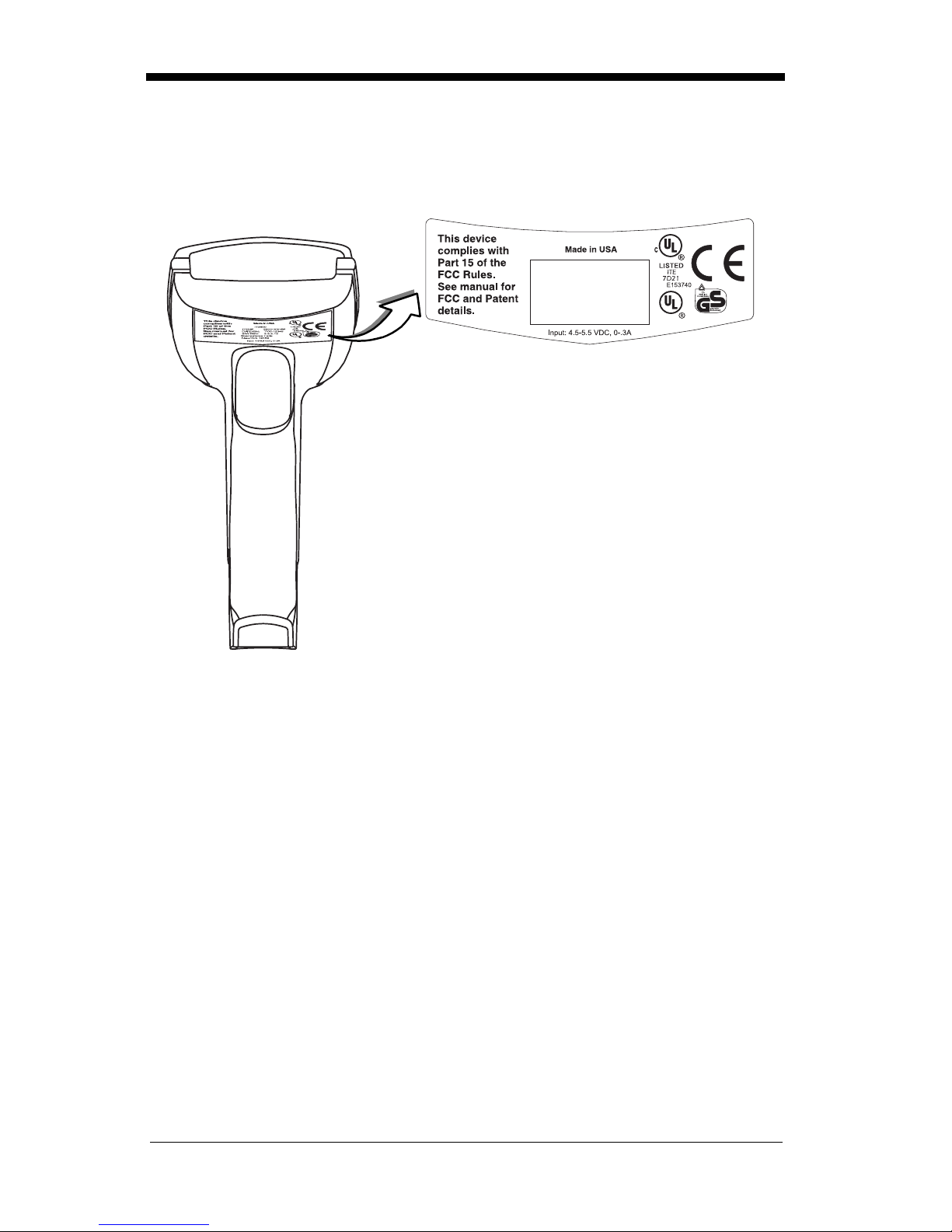
RealScan 7837 High-Performance Scanner
Identification
1 - 3
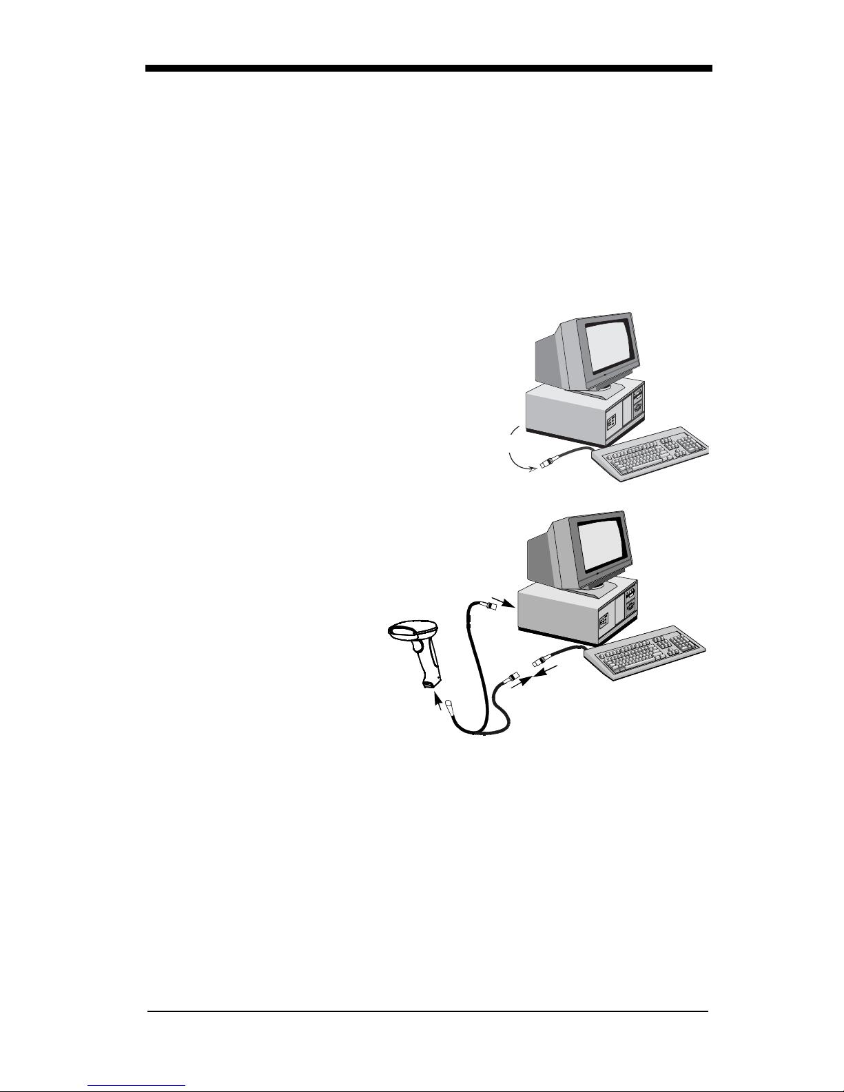
Connecting the Scanner When Powered by Host
(Keyboard Wedge)
A scanner can be connected between the keyboard and PC as a “keyboard
wedge,” plugged into the serial port, or connected to a portable data terminal in
wand emulat ion or non decod ed outpu t mode. The fo llowing is an ex ample of a
keyboard wedge conn ec tio n:
1. Turn off power to the terminal/computer.
2. Disconnect the keyboard cable from the
back of the terminal/computer.
Disconnect
3. Connect the appropriate
interface cable to the scanner and to the terminal/computer.
3
4. Turn the terminal/computer power back on. The scanner will beep twice.
5. Verify the scanner operation by sca nni ng a bar co de from the bac k cove r of
this manual. The scanner will beep once.
The scanner is now connected and ready to communicate with your terminal/
PC. You must program the scann er for your inte rface before bar code data can
be transmitted to you r term ina l/PC . If you are us in g the sc ann er as a keyb oard
wedge, turn to page 2-1. If the scanner is connected via a serial port, turn to
page 2-9. If this is a wand emulation application, turn to page 2-16, and for a
non decoded output connection, turn to page 6-2.
1 - 4
1
2

Plug and Play
Plug and Play bar codes provide instant scanner set up for commonly used
interfaces.
Note: After you scan one of the codes, power cycle the host terminal to have
the interface in effect.
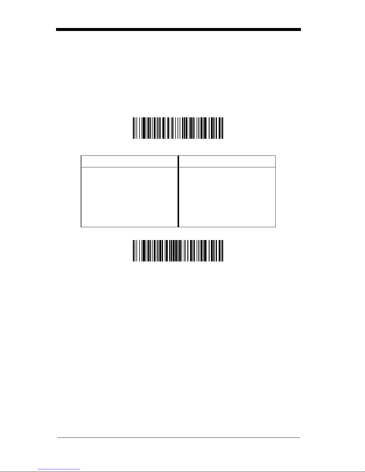
The most common interface is Keyboard Wedge. The following Keyboard
Wedge bar code also programs a carriage return (CR) suffix.
Keyboard Wedge Interface for IBM PC
AT and Compatibles
The following Plug and Play bar code for IBM XT and Compatibles also programs a carriage return (CR) suffix.
IBM XT and Compatibles
The following Plug and Play bar code for IBM PS-2 and Compatibles also pro-
grams a carriage return (CR) suffix.
IBM PS-2 and Compatibles
Use Non Decoded Output Laser Emulation when connecting to a secondary
terminal with i ntegral decoding . This al so sets t he transmi ssion ra te to 36 sc ans
per second and the polarity to white high.
Non Decoded Output
Laser Emulation
1 - 5

For most laptops, scanning the Laptop Direct Connect bar code allows opera-
tion of the integral keyboard. The following Laptop Direct Connect bar code
also prog rams a carriage return (CR) suffix.
Laptop Direct Connect
The RS-232 Interface bar code is used when connecting to the serial port of a
PC or terminal. The following RS-232 Interface bar code adds a suffix of a CR
and LF, and also programs the parameters:
Option Setting
Baud Rate 9600 bps
Parity Even
Data Format 7 data bits, parity bit, 1 stop bit (8 bit data)
RS-232 Interface
In Wand Emulatio n mode, the scanner decod es the bar co de then sen ds data in
the same format as a wand scanner. The Same Code format transmits UPC,
EAN, Code 128 and Interleaved 2 of 5 bar codes without any changes, but converts all other symbologies to Code 39.
Wand Emulation Same Code
The following Wand Emulation bar code sets the interface to Wand Emulation
mode and translates bar code data as Code 39 symbology. It also programs
the Transmission Rate to 25 inches per second, and Output Polarity to black
high.
Wand Emulation (Code 3 9 Form at)
Note: For the 7837-1200-9090 model: When the 7837-1200-9090 interface is
1 - 6

set to wand emulation, all PDF417 bar code data is transmitted as Code
128. Data from other symbologies follow the rules described above.
IBM 4683 Ports 5B, 9B, and 17 Interface
Note: The following Retail “Plug and Play” codes are for use with the 7837-
1000-9090 and 7837-1110-9090 models only.
Scan one of the following “Plug and Play” codes to program the NCR RealScan
7837 High-Performance Scanner for IBM 4683 Port 5B, 9B, or 17.
Note: After scanning one of these codes, you must re-boot the cash register.
IBM 4683 Port 5B Interface
(Default for -11 Models)
IBM 4683 Port 9B HHBCR-1 Interface
IBM 4683 Port 9B HHBCR-2 Interface
IBM 4683 Port 17 Interface
Each bar code above also programs the following suffixes for each symbology:
Symbology
EAN 8 0C
EAN 13 16
UPC A 0D
UPC E 0A
Code 39 00 0A 0B
Suffix
1 - 7

Symbology
Interleave d 2 of 5 00 0D 0B
Code 128 00 18 0B
Suffix
USB Interface
Note: The following USB “Plug and Play” codes (IBM Sur ePO S Hand Held a nd
Tabletop Scanners) are for use with the 7837-1110-9090 model only.
Scan one of the following “Plug and Play” codes to program the NCR RealScan
7837 High-Performance Scanne r for IBM SurePos (USB Hand Held scanner) or
IBM SurePos (USB Tabletop scanner).
Note: After scanning one of these codes, you must re-boot the cash register.
IBM SurePos (USB Hand Held Scanner) Interface
IBM SurePos (USB Tabletop Scanner) Interface
Each bar code above also programs the following suffixes for each symbology:
Symbology
EAN 8 0C
EAN 13 16
UPC A 0D
UPC E 0A
Code 39 00 0A 0B
Interleave d 2 of 5 00 0D 0B
Code 128 00 18 0B
Suffix
1 - 8

Note: The following USB “Plug and Play” codes (USB Keyboard - PC , USB
Keyboard - Mac, and USB HID) are for use with the 7837-1110-9090
model.
Scan one of the following codes to program the NCR RealScan 7837 High-Performance Scanner for USB PC Keyboa rd or USB Macintosh Keyboard. Default
= USB Keyboard (PC).
* USB Keyboard (PC)
USB Keyboard (Mac)
Scan the follo wing code to progra m the NCR RealScan 78 37 High -Performance
Scanner for USB HID bar code scanners.
USB HID Bar Code Scanner
USB Converter
Note: The USB converter is for use with the 7837-1 000-9090, 78 37-1100-90 90,
7837-1002-9090, and 7837-1102-9090 models only.
The 7837
models use a USB co nver ter to sim ulate a USB keybo ard. Dat a flows into a pplications as if entered from the keyboard. The USB converter is compatible with
Apple iMac Series and Windows®98 and later PCs. Use cable set 1416-C7830025 to make the USB port connection.
To set up the USB comm unica tions, find the ter minal ID in the Suppo rted Term inal Chart on page 2-3, and follow the instructions on page 2-2. The PC and
scanner automatically connect. Communications start immediately.
-1000-9090,
7837
-1100-9090,
7837
-1002-9090, and
7837
-1102-9090
1 - 9

OCIA Interface
Note: The OCIA interfaces are only available on the 7837-1000-9090 model.
Scan one of the following “Plug and Play” codes to program the NCR RealScan
7837 High-Performanc e Scanne r for Generic O CIA, NCR OCIA Short Format (8
bit), NCR OCIA Long Format (9 bit), and Nixdorf OCIA.
Note: After scanning one of these codes, you must re-boot the cash register.
Generic OCIA Interface
The Generic OCIA bar code also programs the following prefixes for each symbology:
Symbology
EAN 8 06 06
EAN 13 06
UPC A 01
UPC E 05
Prefix
NCR OCIA Short Format (8 Bit) Interface
NCR OCIA Short Format (8 Bit) Interface
The NCR OCIA Short Format (8 Bit) bar code also programs the following prefixes for each symbol ogy:
Symbology
EAN 8 0F 0F
EAN 13 0F
UPC A 0A
UPC E 0E
Prefix
1 - 10

NCR OCIA Long Format (9 Bit) Interface
NCR OCIA Long Format (9 Bit) Interface
The NCR OCIA Long Format (9 Bit) bar code also programs the following prefixes for each symbol ogy:
Symbology
EAN 8 46 46
EAN 13 46
UPC A 41
UPC E 45
Code 39 42 31
Interleaved 2 of 5 42 32
Code 128 42 33
Prefix
Nixdorf OCIA Interface
Nixdorf OCIA Interface
The Nixdorf OCIA bar code also programs the following prefixes for each symbology:
Symbology
EAN/UPC with Addenda 44 4B
Code 39 44 49
Interleaved 2 of 5 44 48
2 of 5 44 47
Code 128 44 4A
Prefix
1 - 11

Serial Wedge
The NCR RealScan 7837 High-Performance Scanner uses true and TTL signal
levels to wedge into an RS-232 serial network. Use 7837 serial wedge cables
only to prevent damage to the scanner. Refer to the serial interface programming (pages 2-9 to 2-13) to set the baud rate and co mmunications protocol.
To set up the seria l wedge terminal I D, fin d the te rminal ID in the Support ed Terminal Chart and follow the instructions on page 2-2. Set the port to which you
want the scanned data to transmit. Port 1 corresponds to P1 on the output
cable and Port 2 corresponds to P2 on the output cable. Choosing Both sends
scanned data to P1 and P2.
Default = P1.
* P1
P2
Both P1 and P2
1 - 12

2
Terminal Interfaces
Keyboard Wedge Connection
NCR RealScan 7837 High-Performance Scanners are factory programmed for
a keyboard wedge interface to an IBM PC AT with a USA keyboard. If this is
your interface and you do not need to modify the settings, skip to Chapter 3 Output.
If you have a different terminal and/or you want to make any keyboard wedge
changes, scan the bar code below.
IBM PC AT and Compatibles
with CR suffix
2 - 1

Terminal ID
If your interface is not a standard PC AT, refer to "Supported Terminals" on
page 2-3 through page 2-4, and locate the Terminal ID number for your PC.
Scan the Terminal ID bar code below, the n scan the numeric bar co de(s) on the
inside back cover of this manual to program the scanner for your terminal ID.
Scan Save to save your se lection.
For example, an IBM AT terminal ha s a Terminal ID of 003. You would scan the
Terminal ID bar code, then 0, 0, 3 from the inside back cover, th en Save. If you
make an error while scanning the digits (before scanning Save), scan the
Discard code on the back cover, scan the Terminal ID bar code, scan the
digits, and the Save code again.
Terminal ID
Save
Note: After scanning one of these codes, you must power cycle your computer.
The RealScan 7837 High-Performance Scanner can interface to most retail
terminals available on the market today. Contact NCR for terminals not in the
following list.
2 - 2

Supported Terminals
Terminal Model(s) Terminal ID
Apple Mac Mac Classic, SE SE30, II (All) 049 **
Apple Mac Powerbook 5300 Series (Portable PC) 049 **
DEC VT510, 520, 525 (PC style) 005
DEC
Esprit 200, 400 005
Heath Zenith PC, AT 090
HP Vectra 003
HP Vectra ES 023
IBM XT 001
IBM PS/2 25, 30, 77DX2 002
IBM
IBM 102 ke y
IBM 122 key 3191, 3192, 3471, 3472 007
IBM 122 ke y
IBM 122 key 3180 024
IBM 122 key 3180 data entry keyboard 114
IBM DOS/V 106 key PC & Workstation 102
IBM SurePOS USB Hand Held Scanner 128****
IBM SurePOS USB Tabletop Scanner 129****
IBM Thinkpad 360 CSE, 340, 750 097
IBM Thin kpad 106
IBM Thinkpad 365, 755CV 003
I/O 122 key 2676D, 2677C, 2677D 008
ITT 9271 007
Lee Data IIS 007
NEC 98XX Series 103
Olivetti M19, M200 001
Olivetti
RS-232 True 000***
RS-232 TTL 000
Serial Wedge 050
Silicon Graphics Indy, Indigoll 005
VT510, 520, 525 (DEC style
LK411)
AT, PS/2 30–286, 50, 55SX,
60, 70, 70–061, 70–121, 80
3161, 3162, 3163, 3191, 3192,
3194, 3196, 3197, 3471, 3472,
3476, 3477
3196, 3197, 3476, 3477, 3486,
3482, 3488
M240, M250, M290, M380,
P500
104
003 *
006
008
003
2 - 3

Supported Terminals (Continued)
Terminal Model(s) Terminal ID
078, 078A, 79, 80, 191, 196,
Telex 88 key
Telex 88 key Data Entry Keyboard 112
Telex 102 key
Telex 122 key
USB converter 124
USB PC Keyboard 124
USB Mac Keyboard 125
Wand Emulation 061
* Default for -12 model
** Applies to -12 models only
*** Default for -13 model (applies to -13 models only)
**** Applies to 7837-1110-9090 model only. Because special suffixes are
required by the IBM SurePOS terminal, it is best to use the Plug and Play bar
codes on page 1-7 to program these interfaces, rather than scanning the
terminal ID listed in this table.
See page 1-7 for -11 model default.
1191,1192, 1471, 1472, 1476,
1477, 1483
078, 078A, 79, 80, 191, 196,
1191,1192, 1471, 1472, 1476,
1477, 1483
078, 078A, 79, 80, 191, 196,
1191,1192, 1471, 1472, 1476,
1477, 1482, 1483
025
045
046
2 - 4
Keyboard Country
Scan the Program Keyboard Country bar code below, then scan the numeric
bar code(s) from the inside back cover, then the Save bar code to program the
keyboard for your country. As a general rule, the following characters are not
supported by the scanner for cou ntri es othe r than the U nite d States:
@ | $ # { } [ ] = / ‘ \ < > ~
Program Keyboard Country
Country Code Scan Country Code Scan
Belgium 1 Italy 5
Denmark 8 Norway 9
Finland 2 Spain 10
France 3 Switzerland 6
Germany/Austria 4 USA (Default) 0
Great Britain 7
Save
2 - 5

Keyboard Style
This programs keyboard styles, such as Caps Lock and Shift Lock.
Regular.
Regular
Caps Lock
Shift Lock
to U.S. keyboards).
is used when you normally have the Caps Lock key off.
* Regular
is used when you normally have the Caps Lock key on.
Caps Lock
is used when yo u no rmally have the Shift Loc k k ey on (not common
Default =
Shift Lock
Automatic Caps Lock
The software tracks and reflects if you have Caps Lock on or off (AT and PS/2
only). This selection can only be used with systems that have an LED which
notes the Caps Lock status.
is used if you change the Caps Lock key on and off.
Automatic Caps Lock
2 - 6
 Loading...