

NCR RealScan 7802 User Manual

RealScan 7802 Price Verifier
User Guide
497-0425530
Release E
June 2003
Information Products
RSD-Atlanta

NCR RealScan 7802 Price Verifi er User Guide
The product described in this book is a licensed product of NCR Corporation.
NCR RealScan is either a registered trademark or a trademark of NCR Corporation in
the United States and/or other countries.
It is the policy of NCR Corporation (NCR) to improve products as new technology,
components, software, and firmware become available. NCR, therefore, reserves the
right to change specifications without prior notice.
All features, functions, and operations described herein may not be marketed by NCR in
all parts of the world. In some instances, photographs are of equipment prototypes.
Therefore, before using this document, consult with your NCR representative or NCR
office for information that is applicable and current.
To maintain the quality of our publications, we need your comments on the accuracy,
clarity, organization, and value of this book.
Address correspondence to:
Manager, Information Products
NCR Corporation
2651 Satellite Blvd.
Duluth, GA 30096
Copyright © 2002
By NCR Corporation
Dayton, Ohio U.S.A.
All Rights Reserved
06/03 497-0425530 Release E2 of 94

NCR RealScan 7802 Price Verifi er User Guide
Table of Contents
Table of Contents......................................................................................................................... 3
Revision Record........................................................................................................................... 6
Chapter 1 – Introduction............................................................................................................ 7
What's in this Manual ............................................................................................................ 7
NCR RealScan 7802 Models.................................................................................................. 7
The RealScan 7802 Description............................................................................................. 7
Technical Knowledge Required............................................................................................ 8
Installation.......................................................................................................................... 8
Operation............................................................................................................................ 8
Application Program Interface (API).............................................................................. 9
Technical Assistance ............................................................................................................10
Service Responsibility..........................................................................................................10
Chapter 2 – Installing the NCR RealScan 7802...................................................................... 11
Items Shipped with the RealScan 7802 .............................................................................. 11
Mounting the RealScan 7802............................................................................................... 11
Mounting to a Wall.......................................................................................................... 12
Mounting to Column....................................................................................................... 12
Mounting to a Pole .......................................................................................................... 12
Mounting to a Stand........................................................................................................ 13
Wiring the Ethernet Model ................................................................................................. 14
Wiring the RF Wireless Model............................................................................................ 15
Entering the ESS ID ......................................................................................................... 15
Setting up a Wireless RF Link........................................................................................ 16
Adding a Serial Printer........................................................................................................ 17
Wiring and Configuring the Serial Port........................................................................ 17
Sending Data to the Printer............................................................................................ 17
Wiring Precautions............................................................................................................... 18
Chapter 3 – Installing the Software......................................................................................... 19
Server Install ......................................................................................................................... 19
Unit Configuration............................................................................................................... 19
NCR RealScan 7802 Software Updates.............................................................................. 20
V3.XX Software................................................................................................................ 20
V4.XX Software................................................................................................................ 20
Chapter 4 – Network Configuration....................................................................................... 21
Introduction........................................................................................................................... 21
Network Activity............................................................................................................. 21
NCR RealScan 7802 Configuration .................................................................................... 22
Quick Start........................................................................................................................ 22
Configuration Information Screens............................................................................... 22
UnitConfig Program........................................................................................................ 24
Using Unit Configuration.................................................................................................... 24
Configuration Rules.............................................................................................................25
WEP Network Security........................................................................................................ 26
WEP Types .......................................................................................................................26
WEP Description.............................................................................................................. 26
Setting WEP...................................................................................................................... 26
497-0425530 Release E 06/03 3 of 94

NCR RealScan 7802 Price Verifi er User Guide
Network Diagnostics............................................................................................................ 27
Diagnostic Configurations.............................................................................................. 27
Diagnostic Screens and Messages ................................................................................. 28
Internal Error.................................................................................................................... 28
Transfer Error................................................................................................................... 28
Connect Error ...................................................................................................................29
Chapter 5 – Interfacing to the Back Office Server................................................................. 31
Overview ............................................................................................................................... 31
Software Developers Kit (SDK).......................................................................................... 32
ProductInfo Protocol Description....................................................................................... 32
Protocol Implementation Rules .......................................................................................... 34
NCR RealScan 7802 Implementation Rules ...................................................................... 34
NCR RealScan 7802 Supported Modes.............................................................................. 35
Fixed Unit Identification................................................................................................. 35
User Configurable Unit identification .......................................................................... 35
Setup for Windows Networking (SMB)........................................................................ 35
RealScan 7802 FTP Server Configuration..................................................................... 36
Setup for FTP, QFX, NTP, PRODUCTINFO ................................................................ 36
Product Query configuration......................................................................................... 36
Presentation configuration ............................................................................................. 37
Multiple Windows........................................................................................................... 38
Real Time Clock Display................................................................................................. 38
Miscellaneous configuration .......................................................................................... 38
Command modes............................................................................................................. 41
Programmatic Modes...................................................................................................... 41
QFX Quick File Transfer Protocol ...................................................................................... 42
Tokens ............................................................................................................................... 42
INFO exchange................................................................................................................. 42
Using Graphics Characters.................................................................................................. 43
Using the Touch Screen ....................................................................................................... 44
Introduction...................................................................................................................... 44
Configuring Scanvue for Input Devices ....................................................................... 44
New Touch Screen Modes.............................................................................................. 46
Chapter 6 – RealScan 7802-2000 Vacuum Fluorescent Display .......................................... 47
Description ............................................................................................................................ 47
Operation............................................................................................................................... 47
Text Slideshow................................................................................................................. 48
Changing Character Sets ................................................................................................ 48
Customer Messages......................................................................................................... 49
Creating Customer Messages on VF Display Models................................................. 50
Appendix A – Configuring with Barcodes............................................................................ 55
Barcode Reader Settings...................................................................................................... 55
Recommended Scanner Settings ........................................................................................ 55
Configuring the NCR RealScan 7802 ................................................................................. 55
Appendix B – NCR RealScan 7802 Initialization File........................................................... 59
Overview ............................................................................................................................... 59
Real Time Clock.................................................................................................................... 59
Rules for the realscan.ini File .............................................................................................. 60
Sections & Commands......................................................................................................... 60
Example of Initialization File .............................................................................................. 63
06/03 497-0425530 Release E4 of 94

NCR RealScan 7802 Price Verifi er User Guide
Appendix C – Creating a Slideshow....................................................................................... 65
Creating a Slideshow File.................................................................................................... 65
Using Multiple Graphic Windows..................................................................................... 65
Rules....................................................................................................................................... 66
Section & Commands........................................................................................................... 66
Multiple Windows Commands ..................................................................................... 66
Example of Slideshow File ............................................................................................. 67
APPENDIX D – Font and Language Sets............................................................................... 71
Graphics (TFT) Display Models ......................................................................................... 71
Vacuum Fluorescent (V) Display Models ......................................................................... 72
APPENDIX E – ProductInfo Protocol..................................................................................... 75
Introduction........................................................................................................................... 75
Protocol Types ...................................................................................................................... 75
Symmetry .............................................................................................................................. 75
Errors...................................................................................................................................... 75
Status Requests ..................................................................................................................... 76
Client Mode Changes........................................................................................................... 76
Packet Types ......................................................................................................................... 76
Nominal Mode Packets........................................................................................................ 77
Client Requirements.............................................................................................................80
Capabilities....................................................................................................................... 80
Modes................................................................................................................................ 80
Appendix F – Mounting Bracket Outlines............................................................................. 81
Appendix G – Application Notes............................................................................................ 85
Wallpaper .............................................................................................................................. 85
Description ....................................................................................................................... 85
Creating Wallpaper ......................................................................................................... 86
Using Wallpaper.............................................................................................................. 86
Text Over Graphics (Mixed Mode) Operation ................................................................. 87
Default Text Setting......................................................................................................... 88
Single TIB.......................................................................................................................... 88
Appendix H – Regulatory Information.................................................................................. 89
Safety Warnings.................................................................................................................... 89
Servicing ........................................................................................................................... 89
Fuse Replacement............................................................................................................ 89
Power Supply Cord Used as Disconnect Means ......................................................... 89
Grounding Instructions................................................................................................... 89
Radio Frequency Interference Statements......................................................................... 90
Federal Communications Commission (FCC) ............................................................. 90
Canadian Department of Communications ................................................................. 91
Voluntary Control Council for Interference (VCCI) ................................................... 91
International Radio Frequency Interference Statement.............................................. 91
European Union Countries............................................................................................. 91
Laser Safety ........................................................................................................................... 92
Laser Safety Label............................................................................................................ 92
Laser Power...................................................................................................................... 92
Declaration of Conformity .................................................................................................. 93
497-0425530 Release E 06/03 5 of 94

NCR RealScan 7802 Price Verifi er User Guide
Issue Date Remarks
A 06/10/02 First Issue
B 07/29/02 Added Service Responsibility (page 8) and updated Appendix A
C 09/12/02 Added Serial Printer information
D 12/12/02 Updated to software version 5.0
E June 2003 Updated Chapter 5, Using the Touch Screen
Revision Record
06/03 497-0425530 Release E6 of 94

What's in this Manual
This manual provides instructions for installation and operation of the NCR
RealScan 7802 Price Verifier. Included is a description of the basic functions and features
of the hardware. Following this is description of how to physically install the unit in its
intended location, set it up to operate on your specific network, configure your network,
and interface the RealScan 7802 to a back office server through its Application
Programming Interface (API).
This manual is current with software versions 5.0 and later.
The RealScan 7802 is designed to accept newer software versions downloaded across the
network. For ease of identification the current software version number is displayed on
the first status screen appearing after powering up the unit. Scanning a specific barcode
(see Appendix A) displays the status screen directly; the host can query the unit for the
same information. Future software updates and later versions of this manual are made
available on the NCR web server at www.NCR.com as they are released.
NCR RealScan 7802 Price Verifi er User Guide
Chapter 1 – Introduction
NCR RealScan 7802 Models
The NCR RealScan 7802 family consists of a number of different models that appear
externally identical but have different features. The RealScan 7802-1001 is a hard-wired
only unit with a ¼ VGA color AMLCD display. The RealScan 7802-2001 has an optional
11Mbps (IEEE 802.11b) wireless Ethernet interface installed while the RealScan 78022000 has a 4x20 fixed width character vacuum fluorescent (VF) display with optional
wireless Ethernet. The RealScan 7802-3000 has RS-232 communicaitons. Each of these
models can have an optional bank of four switches on the front panel. These switches
have no pre-assigned functions but when depressed can send switch number and time
open and close events to the host computer. The user may utilize these switch events in
the host software in any manner desired. All models are transparent to the API – that is,
they may be interchanged without having to modify host computer software or your
network.
The RealScan 7802 Description
The RealScan 7802 is a multi-function price verifier designed to permit a retail store
customer to check the price of any UPC barcoded product without having to leave the
aisle or shelf area. As well as displaying the price and description of scanned items, The
RealScan 7802 color graphics LCD can show continuous advertising of specials or
promotions, display manufacturers “paid – for” advertising or provide other customer
information. Thus, as well as performing a service to the customer, The RealScan 7802
can directly generate advertising revenue for the store. The advertising display can be
sequential still images (slides), short animation clips, text, graphics or a mix of all these
types of display.
The contemporary housing design merges well with almost any store décor and custom
color combinations are available if the units are ordered in sufficient quantities. Several
different ways of mounting the RealScan 7802 unit in the aisle, on a column, at an
endcap or at a POS location are available.
497-0425530 Release E 06/03 7 of 94

NCR RealScan 7802 Price Verifi er User Guide
The basic RealScan 7802 consists of the following components.
• Barcode scanner in the underside of the housing
• 5½”, ¼ VGA color graphics LCD display or optional 4/20 vacuum fluorescent
display
• 4 optional front panel push button switches to perform any function required by
user
• Embedded microprocessor based controller that manages the operation of the unit
Communications between the RealScan 7802 and the host computer may be hardwired
10baseT Ethernet or wireless 802.11x. An external RS-232 serial port is available through
an optional Y cable and supports a hand-held scanner, a coupon printer, or any other
serial device.
The electronics package is completely contained in a high impact ABS injection molded
case. An integral metal bracket permits the unit to be mounted in several different ways
with the addition of optional parts. The unit meets most worldwide regulatory safety
and EMC standards including UL 1950, CSA22.2, FCC, CDRH and CE.
Technical Knowledge Required
Installation
The installation of the RealScan 7802 is a reasonably easy process for a person familiar
with installing and maintaining local area networks (LAN’s). Although NCR has
provided various software tools to help with the network setup, this manual is not
intended to be a training guide for novice network installers. It is assumed the
installation is done by a person having a sufficient level of technical expertise with LAN
hardware and software to understand the content of this manual and complete the job
with minimal outside help. A system or network administrator is capable of performing
the installation with ease. NCR can provide additional technical assistance in getting the
system running, if required.
Operation
Once the RealScan 7802 units are installed and configured, a graphics based
presentation (slideshow) can be created. This can be done by anyone who is familiar
with a PC and can write simple macros or script files. The slideshow is created using
Microsoft WordPad™ or similar text editor. Image files can be obtained from many
sources – downloaded from a website, scanned in from a digital scanner, or transferred
from a digital camera. Familiarity with a graphics editor program would be helpful in
preparing the images for slideshow presentations.
06/03 497-0425530 Release E8 of 94

Application Program Interface (API)
An API that provides the interface between the RealScan 7802 and the network host
computer application is described in detail in this document. The API is written in ANSI
“C” and can be integrated with any ANSI ‘C’ compiler. The database application and its
interface to the RealScan 7802 generally resides on the network host computer
(sometimes called the network server). Any one of numerous different hardware or
software platforms may be used as long as TCP/IP is the network transport protocol.
Typical platforms are AS400, VAX or Wintel hardware running Windows
NT/2000/ME/XP, Unix, VMS, Oracle, SQL….
The database application program is responsible for receiving a request from a scanner,
retrieving the price and description from the database and returning that data to the
unit that initiated the request. The development and maintenance of any host computer
based application program required to access a product information database is the sole
responsibility of the end user or their system integrator. NCR provides an SDK
including some license free “C” source code to assist the end user in writing
applications on their host machine.
NCR RealScan 7802 Price Verifi er User Guide
497-0425530 Release E 06/03 9 of 94

NCR RealScan 7802 Price Verifi er User Guide
Technical Assistance
Should you need technical assistance installing or troubleshooting your scanner, please
call the Help Desk for your region.
• In the United States: 1-800-262-7782
• In other countries: use the number for your regional Help Desk
Service Responsibility
NCR is responsible for replacing a faulty NCR RealScan 7802 Price Verifier and
ensuring that the scanner in the replacement unit is set to factory default parameters.
Refer to Recommended Scanner Settings in Appendix A for information about doing this.
The customer is responsible for setting all parameters required for the unit to operate
within their network environment. The customer is also responsible for assuring that all
units communicate properly within their network – NCR is not equipped to perform
this function.
06/03 497-0425530 Release E10 of 94

Chapter 2 – Installing the
Items Shipped with the RealScan 7802
• The RealScan 7802 with barcode scanner and Display.
• DC power supply. A 24Vdc/20W AC outlet mounted 'brick' with a standard 8 pin
DIN female connector. The Power Supply is available in 120 or 240 Vac input
voltages. 120 Vac units are UL/CSA approved. 240 Vac units are CE and worldwide
approved.
• SDK (software developers kit). Includes programs for and setting up the
RealScan 7802 unit and the server, API code, demo programs, font files, user
manuals in PDF format, and several useful utilities. This can be requested.
• Mounting hardware – depending on the model ordered, all necessary special
hardware for wall mounting, column mounting, or a desk stand are supplied.
• Available accessory – 6' DC power extender cable with DINF to DINM connectors.
• Available accessory – Y cable for RS-232 hand-held scanner.
• Available accessory – Y cable for serial printer.
NCR RealScan 7802 Price Verifi er User Guide
NCR RealScan 7802
Mounting the RealScan 7802
Caution: Read entire section prior to mounting a the RealScan 7802 unit
There are four ways the RealScan 7802 can be mounted. All four of these mounting
methods utilize the same basic wall mount bracket provided with each unit. The pole
mount, stand mount, and plate mount kits are options.
• Wall mounted from the back of the unit.
• Wall mounted from the back of the unit with a strengthening backplate.
• Pole mounted to a support column from the back of the unit.
• Stand mount for attaching to a flat surface.
The wall mount bracket is a U shaped channel that slides into slots in the housing from
the back of the unit. Bosses molded in the side of the housing snap into two spring clips
attached to the inside of the bracket to positively lock the housing to the bracket. To
release the housing from the bracket, push flat blade screwdrivers into the two slots, one
on each side, located on the underside of the mounting bracket. This forces the springs
out of the locating bosses so the bracket can be pulled out of the housing.
497-0425530 Release E 06/03 11 of 94
Wall Mount Bracket
20036

NCR RealScan 7802 Price Verifi er User Guide
The wall mount bracket and housing are specifically designed to make installation easy.
Removal has been made far more difficult to prevent vandalism. Unless you know
exactly how to do it, removal is almost impossible without destroying the unit.
Mounting to a Wall
1. Remove the bracket from the housing by pushing flat blade screwdrivers into the
release slots in the bottom of the mounting bracket.
2. Hold the bracket up to the wall where you want to mount the unit, slots facing
down, and drill the 3 (or 4) mounting holes.
3. Using an appropriate fastener for the type of wall, attach the bracket securely, slots
facing down.
4. Slide the RealScan 7802 housing onto its bracket until it snaps in place – the housing
should slide all the way onto the bracket with the rear touching the back of the
bracket when it snaps in. If the RealScan 7802 has connectors hanging down, make
sure they are not caught between the bracket and the housing.
CAUTION: Do not install mounting bracket with the slots facing up. The bracket cannot
be removed again without disassembling the unit.
Mounting to Column
1. For columns larger than 18” in diameter, regardless of construction, either wall
mount bracket may be used with shim washers on the outer mounting screws
between the U bracket and the column. Sufficient washers should be used to
prevent the bracket from bowing when it is secured in place. The width of the U
bracket should be 6” at the open end of the U when correctly mounted and not
bowed.
2. Slide the RealScan 7802 housing onto its bracket until it snaps in – the housing
should slide all the way onto the bracket with the rear touching the back of the
bracket when it snaps in. If the RealScan 7802 has connectors hanging down, make
sure they are not caught between the bracket and the housing.
Mounting to a Pole
CAUTION: The pole mount should only be used on rigid aluminum or steel poles less
than 18” in diameter. Wood, plastic or other compressible materials are not suitable for
use with the pole mount.
1. Any column under 18” in diameter is called a pole in this section. A pole-mounted
unit uses the same wall mount bracket previously described with the addition of a
piggyback pole bracket and a worm drive flexible strap.
06/03 497-0425530 Release E12 of 94
NCR RealScan 7802 Price Verifi er User Guide
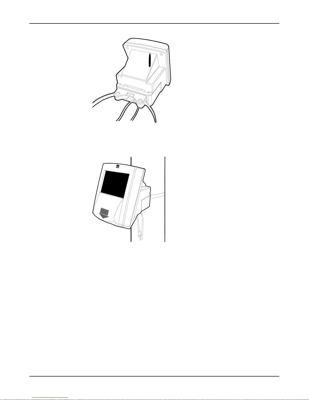
2. Feed the strap though the two guides in the pole bracket. Position the mounting
bracket at the height required on the column, then pass the flexible strap around the
column and secure it tightly. Cut off the excess strap and remove any burrs.
19449
20022
3. Slide the RealScan 7802 housing on to the bracket until it snaps in – the housing
should slide all the way onto the bracket with the rear touching the bracket when it
snaps in. If the RealScan 7802 has connectors hanging down, make sure they are not
caught between the bracket and the housing.
Mounting to a Stand
1. The desktop stand is attached to the same wall mount bracket described above. The
stand is screwed to the rear of the wall mount bracket.
497-0425530 Release E 06/03 13 of 94

NCR RealScan 7802 Price Verifi er User Guide
2. Remove the front cover of the stand and mark the position of the two holes in the
base for mounting it to a horizontal surface. The two connectors are routed down,
inside the stand, and exit from the bottom. A hole may be drilled in the mounting
surface to permit the connectors to pass through to the inside of a cabinet to hide the
installation.
3. Slide the RealScan 7802 housing onto its bracket until it snaps in – the housing
should slide all the way onto the bracket with the rear touching the back of the
bracket when it snaps in. If the RealScan 7802 has connectors hanging down, make
sure they are not caught between the bracket and the housing.
20023
Wiring the Ethernet Model
Once the RealScan 7802 unit is mounted in place there are only 2 cables that have to be
connected before it can be operated. For aesthetic reasons NCR suggests the AC and
network outlets are mounted close to (or in) the ceiling or close to the floor. The two
cables may also be routed inside the wall or column and plug into the AC and network
connections in the ceiling. This is the recommended method and provides the cleanest
installation.
1. Plug the RJ45 cable Ethernet cable connected to the hub or switch on your LAN into
the RJ45 connector in the rear of the RealScan 7802.
2. Connect the 8-pin DIN extension cord and the DIN connector coming from the
RealScan 7802 unit. Line up the arrows on the two connectors and the pins are
aligned for insertion. On later production units, the 8-pin DIN connector is mounted
on a PC board that is accessible from the back of the unit underneath the mounting
bracket. The RJ45 Ethernet connector is also mounted on this PC board.
06/03 497-0425530 Release E14 of 94

3. Plug the other end of the DIN extension cord into the DIN connector on the power
supply.
4. Plug the power supply into a grounded electrical outlet – the RealScan 7802 unit
starts its boot up sequence. Both 120V and 240VAC power supplies are available.
Wiring the RF Wireless Model
If you purchased the wireless Ethernet option, the IEEE 802.11b RF Network Interface
Card (NIC) already is installed and tested at the factory. There is another version called
“RF ready”. This version has the familiar IEEE 802.3 RJ45 Ethernet connector installed as
well as the internal slot for the RF NIC card – although it is not installed. You an easily
recognize the RF wireless option by the short antenna on top of the housing. The
installation is the same as previously described for a hardwired unit except for step 4,
which is not required (unless its an RF ready unit in which case connect the RJ45 to a
hub with a CAT5 patch cable). The end user is responsible for providing and installing a
compatible RF access point to the network and making it operational.
NCR RealScan 7802 Price Verifi er User Guide
20024
The RealScan 7802 wireless NIC card is an 11Mbps, DSSS, Wi-Fi compatible PCCARD
and should communicate with most Wi-Fi compatible access points. Installation of RF
communication links requires special expertise and is part of your site network and as
such the manufacturer of the access point (and your network staff) should be the first
line of technical support. Most of the manufacturers of access points have extensive
technical documentation on performing RF site surveys and correct installation of the
units on their web sites.
Entering the ESS ID
Each wireless RF access point has a unique identification (ESS ID) that consists of up to
32 letters and numbers. When a new unit is shipped from the factory, a default ESS ID
(INSTALL) is stored in configuration memory. Before the RealScan 7802 can
communicate with the access point, it must have a matching ESS ID entered into its
memory to replace the default. The ESS ID can only be entered through the unit’s
internal barcode reader.
The ESS ID is a barcode label in the following format.
NN nn x1 …… x32
where NN = fixed characters, nn = # of characters in ID (1-32)
x1 …… x32 = ID (1-32 characters)
497-0425530 Release E 06/03 15 of 94

NCR RealScan 7802 Price Verifi er User Guide
Load the ESS ID as follows.
1. Create a barcode label with the ESS ID formatted as described above.
2. Power the RealScan 7802 unit and verify the barcode scanner is operational – look at
the underside and check the scanner is lit and rotating.
3. Scan the ESS ID barcode you created.
4. Scan the “Record Settings” barcode.
5. The RealScan 7802 reboots and should now start to communicate with the network.
Setting up a Wireless RF Link
Before installing a new wireless RF data link, it is important to perform an RF site
survey to characterize the immediate environment and ensure a reliable system is
designed. The general pointers indicated here assist in the initial installation and
diagnosis of a link problem, however your first line of technical support is the
specialized help available from the manufacturer of the access point or your VAR or IS
personnel doing the installation.
1. Unobstructed line-of-sight is best. If you can, arrange the RealScan 7802 units so
there is an unobstructed line-of-sight to the access point. Under these ideal
conditions and assuming no interference from other 2.4Ghz sources, you should get
up to 150’ distance. In a typical office or retail environment 30’-50’ is more typical.
2. Mount the access point as high as possible in the line-of-sight. This way the signals
should travel above racks, shelving, customers, etc. The human body is 90% water
and a good RF signal absorber – this is why cell phones often don’t work well inside
buildings and around crowds of other people.
3. Keep reflective surfaces like mirrors and polished stainless steel surfaces to a
minimum and away from the antenna’s as much as possible.
4. If you are having trouble making a connection try moving the RealScan 7802 closer
to the access point, raising it or lowering it.
As the RealScan 7802 unit cannot easily be moved once installed, it is often more
convenient to have a portable signal strength meter or an IEEE802.11b RF NIC card
in a Windows based laptop computer during installs. The Windows NIC card driver
has a similar RSSI graph or displays the signal strength as a percentage depending
on the NIC card used.
06/03 497-0425530 Release E16 of 94

Adding a Serial Printer
Software versions 4.16 and later provide support for an external serial printer as well as
the hand-held scanner. The factory default setting for serial port 2 is SCANNER for the
hand scanner. If a serial printer is required instead of the scanner, serial port 2
configuration must be changed to OUTPUT. The port may also be disabled by setting it
to NONE. You must also purchase a special Y cable that exposes the external RS232 port
to connect the printer to RealScan 7802. This cable comes with a DB9 female connector
and connects directly to the NCR 7197 Thermal Receipt Printer connector. Other
manufacturers serial printers may require a different cable. Check with the factory
before attempting to connect a different printer.
In OUTPUT mode, serial port 2 is an output only, RS232 data port. The RealScan 7802
receives pre-formatted data and control codes from a printer driver resident on the
network host, which it passes, unmodified, through serial port 2 to the printer. Printer
drivers are specific to the printer used and are the responsibility of the user.
Wiring and Configuring the Ser i al Port
Use the modeset utility to change the serial port configuration to OUTPUT mode. If you
are using an MS Windows system, open a DOS box and change to the C:\POS directory
where modeset is stored and send the 2 following lines. The modeset utility, found on
the CD-ROM, must be copied onto the server before these commands can be sent.
NCR RealScan 7802 Price Verifi er User Guide
C:\POS modeset -iPort2function = OUTPUT <IP> ↵
C:\POS modeset -c -r <IP> ↵
where <IP> is the unit’s IP address.
The default serial port 2 settings are 9600 baud, no parity, 8 data bits, 1 stop bit. The
printer port settings must be set to the same parameters as serial port 2 to be able to
communicate with the RealScan 7802. If you want to run the printer faster or change
other parameters, a utility program PortSet is provided on the CD-ROM for modifying
serial port settings.
Sending Data to the Printer
The host server must use nominal-mode ProductInfo packets to send data to the printer.
The packets required are Data type, Special Text sub-type. Following is an example of a
typical message.
Byte Count Value (Oh) Meaning
0-3 00 00 00 13 Length of packet (19 bytes)
4-7 44 41 54 41 'DATA' Data type
8-11 53 50 45 43 'SPEC' Special Text sub-type
12-18 48 65 6C 6C 6F 21 0A 'Hello!<LF>' Text sent to printer
497-0425530 Release E 06/03 17 of 94
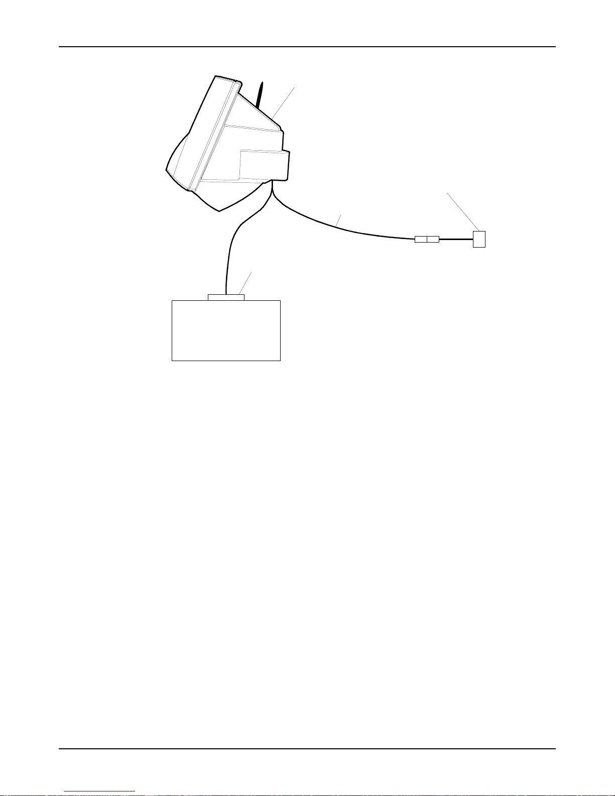
NCR RealScan 7802 Price Verifi er User Guide
Serial Printer
RealScan 7802
Power Supply
Provided With RealScan 7802
Y Cable
DB9 Female Connector
Wiring Precautions
While The RealScan 7802 is designed to withstand power and data line surges, spikes
and other anomalies in accordance with IEC and CE specifications, it is not designed to
survive a direct lightning strike. In parts of the USA and worldwide where there is a
high likelihood of thunderstorm activity it is good practice to install lightning surge
protectors on all power and data lines. The RealScan 7802 should be treated like any
other network and computer product installed in your facility.
20255
06/03 497-0425530 Release E18 of 94

NCR RealScan 7802 Price Verifi er User Guide
Chapter 3 – Installing the
Software
The SetupServer program on the CD-ROM must be run on your Windows network
server to create a specific RealScan 7802 directory called POS on your servers’ hard
disk, share it and copy the default realscan.ini file into this directory. RealScan 7802
units look for this .ini file in the POS directory when they boot up and can not operate if
they can’t find it.
You should also install Unit Configuration on the server as it provides the easiest way to
change the configuration of a unit on the network (as opposed to scanning barcodes).
You may also install Unit Configuration on a desktop or laptop computer for initially
setting up RealScan 7802 units without a network complicating it. You need a network
interface card (NIC) installed in your PC and configured properly to communicate with
the RealScan 7802.
For servers that are running other than Windows, sources are provided for the server
software. There are also freely available drivers to permit any operating system to act as
a Windows-type server.
Important: The shared RealScan 7802 directory and the realscan.ini file must be on the
server and the RealScan 7802 units must be able to find them when they power up. If
you want to change the operating modes (or configuration) of a specific unit anytime
after the system is up and running, the Unit Configuration program is available in the
NCR directory.
Server Install
When you place the NCR SDK CD-ROM (NCR part number 497-0426202) into a drive,
the autoplay feature opens a window with the folders and program icons. Click on the
NCR icon SetupServer and the install program leads you step by step through the
process of creating the POS directory, sharing it, and copying the realscan.ini file into
the directory.
Server install also creates a font directory under POS and loads all the fonts on the CDROM into this directory. The RealScan 7802 has one default font set programmed into
the unit. This is a 16x32 pixel glyph containing all 256 characters of the extended ASCII
character set – thus any Latin based language can be supported from this font set.
Unit Configuration
Click on the NCR icon UnitConfig in the SDK CD-ROM window and the Unit
Configuration program is installed. This program which consists entirely of the one
screen shown in the section on using Unit Configuration, implements the specific set of
commands and controls defined in the API for the RealScan 7802 (see Interfacing to the
Back Office Server). The program is written in Visual Basic® and the sources and an OCX
are provided on the CD-ROM so users can write directly to this program and make
initiate mode changes from their application program
497-0425530 Release E 06/03 19 of 94

NCR RealScan 7802 Price Verifi er User Guide
NCR RealScan 7802 Software Updates
There are 2 basic models of the RealScan 7802 that utilize different internal processors
and operating systems. This is transparent to the customer and the API user and there
are no external functional or physical differences between the models with the exception
of the process for online software updates. Future software releases include both update
methods for both types of units.
When new software is loaded into the RealScan 7802, the file image is written into RAM
memory. A CRC is calculated and compared with the CRC appended to the file sent
from the host. If the two CRC’s are identical, the file has been loaded without errors and
it is then written into flash memory. The unit does not reboot itself and run the new
software.
The model type is easily identified by the software version number on the status screen
when the unit is booted.
V3.XX Software
If the software version is 3.xx, then use the FLASH.BAT batch program to update the
software. When the new software image is finished loading, FLASH.BAT immediately
reads back the status of the file transfer and the flash write process by reading the
ERRMSG file from the RealScan 7802. ERRMSG returns the CRC of the image and the
number of bytes written.
V4.XX Software
If the software version is 4.xx or later, then use the PUSH.EXE utility provided on the
CD-ROM to load the new program. The command format is:
PUSH <7802 IP Address><updated file name>.
For example: PUSH 10.0.0.13 SVLIN40
It is possible for the user to get a file called EEPROM.BIN from the NCR 7892. This file
contains an encrypted copy of the entire non-volatile memory. The only reason to do this
is for remote diagnostic purposes and NCR recommends the user only do this under the
direct guidance of a technical support engineer. The procedure is to connect to the unit
using FTP set in binary transfer mode, then GET the file EEPROM.BIN.
06/03 497-0425530 Release E20 of 94

Introduction
NCR RealScan 7802 Price Verifi er User Guide
Chapter 4 – Network
Configuration
The RealScan 7802 is a network-connected device that uses industry standard TCP/IP
protocols for communication. Connecting a RealScan 7802 to your network requires the
same kind of preparation as connecting a workstation to your network. This manual
assumes you know how to obtain the relevant information about your existing network
configuration and choose the appropriate configuration parameters so your network
recognizes RealScan 7802 devices. NCR suggests using switches rather than hubs to
connect to RealScan 7802 units as the bandwidth and response time is improved.
The RealScan 7802 has two primary activities – displaying product price and description
and displaying a graphics slideshow. The unit has two primary modes of operation: an
idle mode where a slideshow from 2 to 150 sequential images is continuously displayed,
and a interactive mode where a customer scans an item and price and description
information is returned by the host server. The four buttons on the front panel can be
configured to only be active when in the interactive mode. In order to display product
information, the RealScan 7802 must connect to a host computer that has the product
information stored in its database.
If you are using an MS Windows network, NCR highly recommends Windows NT,
2000, XP, or ME. Windows 95 and 98 can be used as a server for the RealScan 7802, but
they are not supported. NT 4 Server and Windows 2000 provide the best performance in
terms of response speed, especially if you are using a RF wireless system rather than
hardwired Ethernet (10/100baseT).
Network Activity
The RealScan 7802 includes servers for FTP (port 21), ProductInfo (port 1283), and
clients for FTP, SMB (Windows networking), ProductInfo (Product Information
Protocol) and QFX (Quick File eXchange). FTP, SMB or QFX can be used to get the
graphics files for the RealScan 7802’s slideshow. SMB is the default mode.
The RealScan 7802 ships from the factory with the following default network settings.
IP Address:
Sub-Net Mask:
Unit ID:
User Name:
Password:
Windows Server:
Windows Share:
DHCP (10.0.0.227 – some hard-wired models)
255.255.0.0
NCR RealScan 7802
GUEST
None
SVERVE
POS
The RealScan 7802 requires a file server for storing graphics files and a ProductInfo
server (host or back office computer) the price/description database. These servers may
(but do not have to be) the same physical computer. The file server must have the The
RealScan 7802 initialization file (realscan.ini) in its POS shared directory (if SBM-based)
or the default directory for FTP or QFX, and may also have font, graphic, and slideshow
497-0425530 Release E 06/03 21 of 94

NCR RealScan 7802 Price Verifi er User Guide
script files. The file server can be a Windows system, or an FTP or QFX server on any
type of hardware or OS provided it runs TCP/IP.
The RealScan 7802 sends the UPC number read from a barcoded item placed under the
scanner to the ‘ProductInfo’ server on the host computer which uses this number as a
key to find the item in the price and description database(s). After the item records are
retrieved, the host application prepares the response and sends it back to the
RealScan 7802 where the information is displayed. The response can be text only,
graphics only, or a combination of text and graphics.
NCR RealScan 7802 Configuration
There are three ways to configure a RealScan 7802 unit: using its internal barcode reader
to scan special purpose barcodes, across the network using the UnitConfig or modeset
programs, or following the procedure in the ‘Quick-Start Guide.’ Of course the RealScan
7802 must be able to communicate with the server on the network before its
configuration can be changed on the network.
If you are using wireless RF units, you must enter the ESSID of the access point you are
communicating with via the barcode reader before the unit associates with the access
point. Additionally, if your network uses WEP128 security, the RealScan 7802 must be
setup to match the access point.
Quick Start
The CD-ROM contains a short document called the NCR RealScan 7802 Quick-Start Guide
(497-0426228), that describes how to easily configure your units to match the network
settings using a desktop PC and a crossover cable or a passive hub (see the last 2
diagrams on page 27). This is the easiest way to bring up the first few units without the
added complications of a network.
Configuration Information Screens
When the RealScan 7802 boots up, two configuration status screens are displayed
sequentially which show the current settings of the unit. Each screen is displayed for 10
seconds and then the unit gets the slideshow from the server and starts running it. These
two screens can be displayed at any time by scanning the ‘show config screen 1’ and
‘show config screen 2’ barcodes shown in Apendix A. In software versions later than
V4.15, wireless RF configurations are brown text and a light green background and
hardwired Ethernet units are yellow text on a blue background.
06/03 497-0425530 Release E22 of 94

RealScan 5.0 999999
20020923101613 Betal
RealScan
10.0.10.13:1283
DHCP:10.04.12
Mask 255.255.0.0
NCR RealScan 7802 Price Verifi er User Guide
09:15:00 AM
Configuration Status Screen 1
GW 10.0.10.13
SMB SVSERVE
GUEST
Trivial Protocol
ESSID: INSTALL
00:60:B3:66:06:54
09:15:22 AM
Configuration Status Screen 2
A third status screen shown only on demand displays key RF measurements from the
internal wireless radio, which can be used to determine how well the radio is
functioning in its present location. Scanning the ‘show RF stats’ barcode activates this
screen.
20497-A
20497-B
The primary measurements are Channel = channel # used, ANL = average noise level,
ASL = average signal level, and CQ = communications quality. This screen is a
diagnostic aid and is not intended to be a replacement for a thorough site survey if you
are having RF communication problems.
FIRM : 0.8.0
PORT : ESS
SSID : INSTALL
CQ : 92
ASL : 158 TXR : 8
ANL : 0 CHAN : 6
09:14:21 AM
RF Statistics Screen
497-0425530 Release E 06/03 23 of 94
20497-C

NCR RealScan 7802 Price Verifi er User Guide
UnitConfig Program
Configuring RealScan 7802 units over the network requires a GUI program called Unit
Configuration that is installed from the CD-ROM. Generally, configuration by special
barcode is kept for those occasions when a devices network configuration is
incompatible with the local network. Changes can be made off-line that permit the unit
to connect to the network, just like the ‘Quick-Start Guide”, but without needing the PC.
Appendix B describes this method. Once the unit is network compatible the rest of the
configuration can be done through Unit Configuration.
Unit Configuration is a VisualBasic® program that provides a simple graphical way to
query and configure any RealScan 7802 unit. It uses the RealScan 7802 mode controls
(see Interfacing to the Back Office Server) to setup the unit. The program is available in
both source and executable form.
Modeset is an equivalent command–line program that can query and set modes
through a text file or directly from the directory prompt.
Example: Modeset [mode value] Sets the mode to the specified value
Modeset –g [mode] Returns the value of the mode
Modeset Lists all non-hidden modes and their values
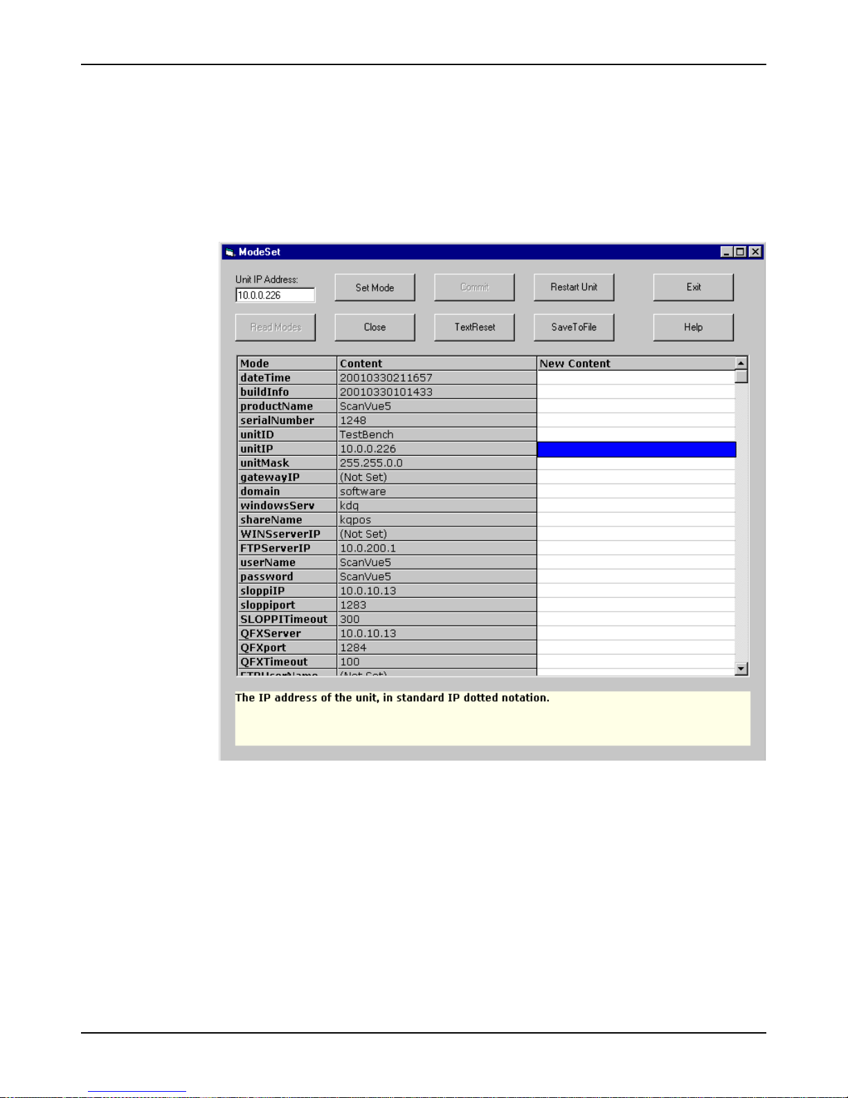
Using Unit Configuration
When the program is first started, all boxes in the screen are blank. Enter the IP address
of the RealScan 7802 unit you wish to change in the Unit IP Address box. Click the
Read Modes button – all the Modes and their Contents (values) are read from the
subject unit and displayed as shown in the following illustration.
To change a mode; highlight the New Content box in the same row as the mode you
want to change by left clicking it. Enter the new value in the box and click the Set Mode
button. If the value is accepted, the box and the button turn green. If it is not accepted,
the box and button turn red. Now click the Commit button, this commits the change to
flash memory in the RealScan 7802 unit. Multiple changes can be made before
committing them. If any of the changes are not accepted, the Set Mode button turns red
and none of the changes are made.
Clicking the Close button blanks the screen including the IP address box and permits a
new IP address, hence a new unit to be selected.
Clicking the TextReset button applies changes made to text modes so they can be seen
immediately; however, like all other modes the changes are not permanently stored
until the Commit button is clicked.
The SaveToFile button saves the screen to a text file where it can be stored and printed
if necessary. This is usually done for troubleshooting or maintaining hard copy records
of each unit's configuration.
The Restart Unit button causes a ‘soft boot’ of the selected unit.
06/03 497-0425530 Release E24 of 94
NCR RealScan 7802 Price Verifi er User Guide
Clicking the Help button brings up a help screen that is a brief overview of how to use
the program. Additionally, the light color area at the bottom of the screen displays
context sensitive help for each mode as the mode is highlighted. For some modes, the
values available are indicated in this area. Other modes (for example Serial Number)
cannot be changed and always turns the New Content box and Set Mode button red.
The Exit button closes the Unit Configuration program.
Configuration Rules
1. Specify the UnitIP as DHCP to have the RealScan 7802 obtain its networking
information from a DHCP server.
2. You may specify any or all of the types of file servers. The one that is used is
determined by the ServerType mode.
3. The –default- has a special meaning: it returns that mode to the factory default
value.
497-0425530 Release E 06/03 25 of 94

NCR RealScan 7802 Price Verifi er User Guide
WEP Network Security
WEP Types
The RealScan 7802 supports four different types of WEP (Wireless Equivalent Privacy)
encryption in software versions 4.12 and later. WEP encryption is set by the
WEPEncryption mode.
WEPEncryption Mode Value Function
NONE WEP encryption off
OPEN40 Open System 40-bit encryption
OPEN128 Open System 128-bit encryption
SHARED40 Shared System 40-bit encryption
SHARED128 Shared System 128-bit encryption
WEP Description
There are four unique encryption keys, WEPKey1 through WEPKey4. Each key contains
10 hex digits for 40-bit encryption or 26 hex digits for 128-bit encryption. Default value
of the keys is a string of zero digits of the appropriate length.
Setting WEP
Before You Start
The mode WEPKeyIndex determines which of the four keys is used. The default is
WEPKey1. The selected key must match the type of encryption selected. For example: if
WEBEncryption is set to SHARED128 and WEPKeyIndex is set to WEPkey2, then
WEPkey2 must contain 26 hex digits (or 128 bits). Neither WEPkeyIndex nor the
encryption data can be set by barcode.
Note: If the encryption type is changed, the RealScan 7802 does not verify that the keys
already stored are appropriate for the new type.
Exception: If you are using Symbol Technologies access points, they do not support
Shared System WEP encryption.
1. The WEP encryption mode and WEP keys for the network you are installing to must
be known.
2. The WEP encryption mode and WEP keys in the access point and the RealScan 7802
must match exactly or they do not associate.
3. When installing and configuring a new or replacement RealScan 7802 into a
network running WEP, you must disable WEP at the access point or the RealScan
7802 does not associate with it.
4. An alternative method is to bring u the RealScan 7802 offline, for example on a
laptop, to set the WEP keys – all the rules still apply but the WEP keys can be
loaded without disabling WEP on your network and UnitConvig can be run locally
rather than on the network server
5. WEP keys are set with the UnitConfig program.
06/03 497-0425530 Release E26 of 94

Procedure
1. Disable WEP in the access point and boot up the RealScan 7802. It should boot up
and associate (connect) with the access point.
2. Run the UnitConfig program.
3. Select WEPEncryption mode and set its value to one of the five choices shown in the
previous table. If WEP is not being used, leave its default setting of NONE.
4. Select WEPKey1 through WEPKey4 and set all four key values.
5. Using WEPKeyIndex set the key value you are using.
6. Commit the changes and reboot the RealScan 7802. New WEP settings take effect
when the unit has finished rebooting.
7. Enable WEP on the access point – provided the WEP encryption mode and WEP key
selected on the RealScan 7802 matches the access point settings, the RealScan 7802
associates (connects) seamlessly.
Network Diagnostics
Diagnostic Configurations
If you are having problems communicating with RealScan 7802 units, NCR highly
recommends that you download a program called EtherHelp® and its technical
documentation from the www.wildpackets.com web site. EtherHelp® is the resident
part of a remote network diagnostic tool (available on the RealScan 7802 CD) and uses
for troubleshooting network problems. There is no charge for this tool. Three useful
network configurations for troubleshooting are shown below.
NCR RealScan 7802 Price Verifi er User Guide
Servers RealScan 7802
This configuration
provides network security
while permitting the
collection of the required
diagnostic information.
This stand-alone
configuration permits the
easy collection of
diagnostic information.
This stand-alone
configuration permits the
easiest collection of
diagnostic information.
20032
Switch Hub
RealScan 7802 Dumb Hub
Crossover Cable
RealScan 7802
PC with
EtherHelp
PC server with
EtherHelp
PC server with
EtherHelp
The hub must be a “dumb” or passive hub, one that does not do any routing. If a switch
or intelligent hub is used, EtherHelp® cannot capture all the packets from the RealScan
7802. When in doubt, the crossover cable is the best solution.
497-0425530 Release E 06/03 27 of 94

NCR RealScan 7802 Price Verifi er User Guide
Diagnostic Screens and Messages
Version 3.10 and later software has a built in diagnostic that automatically attempts to
determine and resolve network connectivity problems when the unit is powered up. By
their very nature diagnostics are not completely fool proof, but they are powerful tools
and many times can pin point problems exactly or provide a strong clue to the actual
problem. The host must be able to ping the unit for the diagnostics to work.
Diagnostic screens have a bright red background, with text displayed in yellow on a
blue background. The first line of the display indicates the type of connection being
attempted – Windows networking (SMB), FTP, or Quick File Exchange (QFX). The unit
displays, at most, one diagnostic screen between restarts. If you have multiple problems
they show up one at a time.
The second line indicates the general class of error, Internal, Connect, or Transfer. The
third line names the specific error, and if a file name is involved, it is displayed on the
fourth line.
Internal Error
Transfer Error
An Internal class error usually relates to a RealScan 7802 device failure and should
never be seen. If the unit can be pinged it is working well enough to eliminate device
failure as a cause of not connecting.
Transfer class errors indicate problems with transferring data over the network after a
connection has been established to the host. Again, the explanations provided are not
necessarily the only possibilities.
Data Transfer
The unit is not able to send messages to the host even though it has a valid
connection. This can be caused by broken server software or for some protocols, by
firewalls between the unit and host.
File Unavailable
The requested file does not exist or security makes it unavailable. This diagnostic
message may display even if everything else is working. It indicates a failure to get
the .INI or the slideshow file. This message displays if the files are available but one
of the graphics is not. This is generally a recoverable error. For the INI and slideshow
files, the unit gets them when they show up; graphic files are bypassed.
No Attribute
This indicates that the Windows server has the file, but cannot provide its size or
time stamp. This is a failure on the host or server.
06/03 497-0425530 Release E28 of 94

Connect Error
NCR RealScan 7802 Price Verifi er User Guide
A Connect error is the most likely type to occur. The explanations given may not be the
only possible reason for the message.
Connect Fail
A general failure to connect to the host. If the host can ping the unit, getting this error
should not be possible.
Connect Timeout
The initial connection was made but the host has not responded to further
communication in timely manner.
Refused
The host is there and the unit can connect to it. The host may not have an appropriate
server running, or security may otherwise refuse to permit the connection.
Logon
The user name and/or password are incorrect.
Protocol Fail
For Windows networking, the unit and the host could not find a mutually acceptable
protocol level.
Share Unavailable
The directory requested does not exist, or is not shared, or protections prevent the
unit from connecting to it.
Host Resolution
The specified host name cannot be resolved to an IP address. This can happen if the
host name is incorrect or if the host is on another subnet and there is no WINS server
available or the WINS server IP has not been set.
Transfer
This may be a transient error that does not re-occur if you power cycle the unit and
try again. Normally you should never see this message, as it indicates a failure of
software and/or hardware on the host, the network, or on the unit.
497-0425530 Release E 06/03 29 of 94
 Loading...