

Page 1
NCM Supplies Inc.
2101 N.W. 79 Ave. Miami, Florida 33122
Phone: 305-640-0461 Fax: 305-639-2684
[email protected] | www.ncmsupplies.com
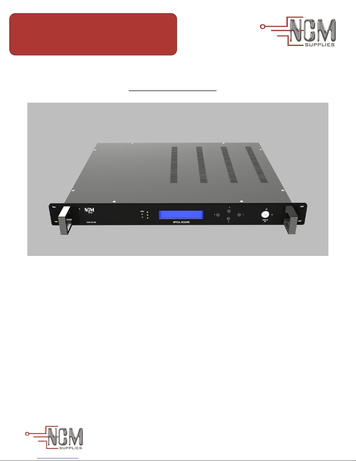
NCM-OR-200
4 Channels Optical Receiver
Installation Guide
Shipping
NCM OPTICS inspects and carefully packs all equipment before shipment. NCM-OR-200 are
completely manufactured and tested by NCM OPTICS.
NCM-OR-200 includes:
1- NCM-OR-200 (1)
2- AC Power Cord (1)
3- Keys (2)
4- Datasheet (1)
6- Installation Guide (1)
MADE IN USA
8125 NW 64th Street, Miami, Florida 33166
1
Page 2
NCM Supplies Inc.
2101 N.W. 79 Ave. Miami, Florida 33122
Phone: 305-640-0461 Fax: 305-639-2684
[email protected] | www.ncmsupplies.com
NCM-OR-200
4 Channels Optical Receiver
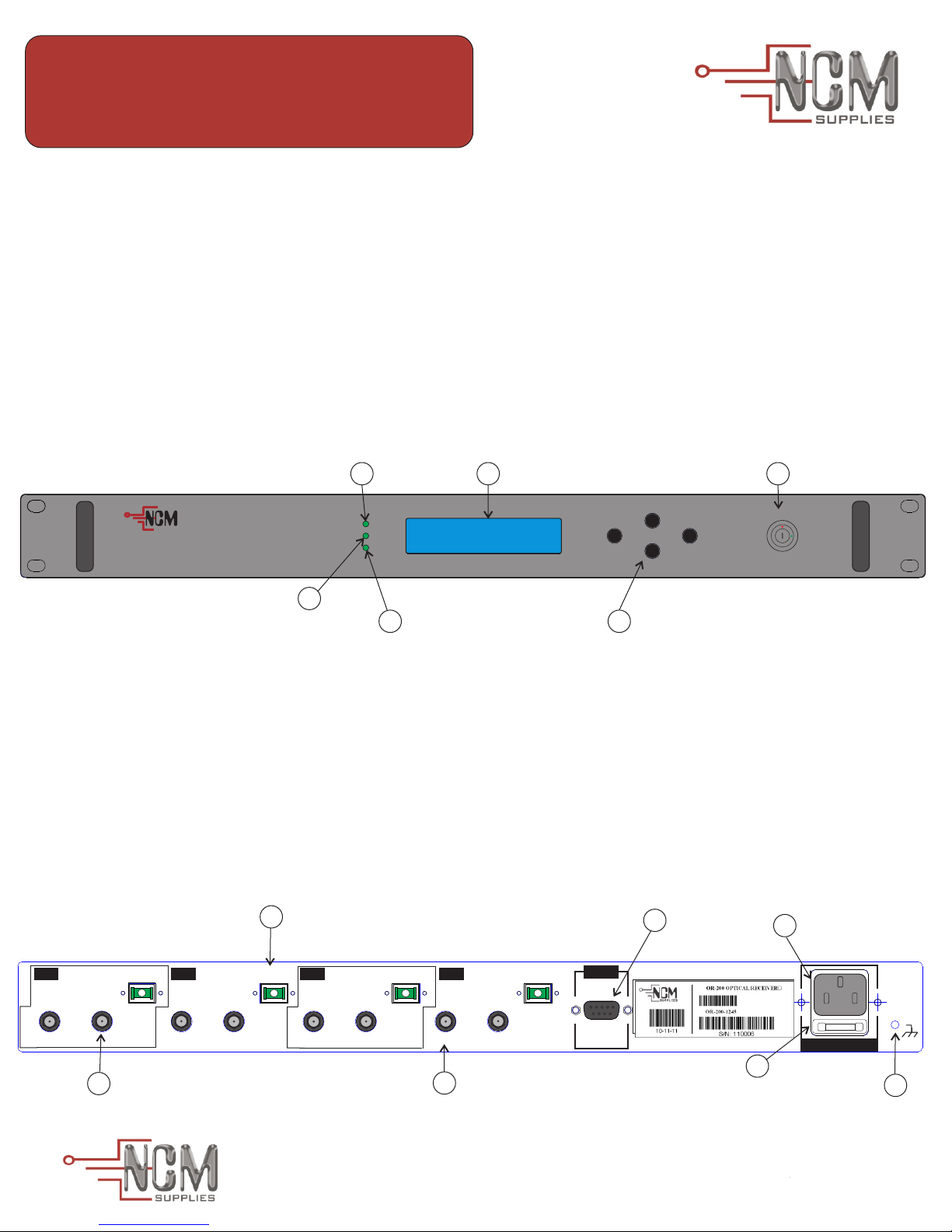
Front Panel:
The front panel is shown in Figure.
1- Power LED- Lights up when the key is turned on.
2- RF LED ALARM-Lights up green when the output RF power is ok or red when out of range.
3- PD LED ALARM- Lights up green when the input optical power is ok or red when out of range.
4- Power On Key- Turns on/off the power
5- LCD- Information Display
6- U, D, R and F key- Four key from key-board
4
POWER ON
OFF
KEY
OPTICS
MODEL OR-200
POWER
1
RF
PD
RX#1 RX#2 RX#3 RX#4
^ OK OFF OK ALM
5
OPTICAL RECEIVER
U
R
D
F
ON
2
3
6
Rear Panel:
The Rear Panel is shown in Figure.
1- RF Output- 75Ω F-type connector input RF signal
2- RS-232- DB9 Serial Monitoring Interface (Bit rate: 9600bps, Data bits: 8, Parity: None, Stop bits: 1)
3- Optical Input-Class 3B, SC/APC or FC/APC connector
RF INPUT
4- Power Jack- Supplies power to the equipment
5- Fuse- A 220V 1.5A fuse to protect the equipment against short circuits and power surges
6- RF Test Point-75Ω F-type connector -20dB input RF signal test point
7- GND-Case ground
3
RX-1
RF-TP
-20dB
RF-OUT
1
OPTCAL IN
RX-2
RF-TP
-20dB
RF-OUT
OPTCAL IN
RX-3
RF-TP
-20dB
RF-OUT
OPTCAL IN
RX-4
RF-TP
-20dB
6
RF-OUT
OPTCAL IN
RS-232
MONITORING
INTERFACE
2
4
110-220 Vac/ 50-60 Hz
5
7
MADE IN USA
8125 NW 64th Street, Miami, Florida 33166
2
Page 3
NCM Supplies Inc.
2101 N.W. 79 Ave. Miami, Florida 33122
Phone: 305-640-0461 Fax: 305-639-2684
[email protected] | www.ncmsupplies.com
NCM-OR-200
4 Channels Optical Receiver
Connections:
RF Connection: The RF-output is located at the rear of the unit. The nominal output level is 30dBmV to
50dBmV. The output connector is 75Ω F-female connector.
The test point in the unit's rear panel is for monitoring the RF output signal. This test point is attenuated -20dB
below RF input signal. The test point connector is 75Ω F-female connector.
Optical Connection: The fiber output is equipped with SC/APC or FC/APC connector. When installing the
fiber, do not exceed minimum bending radius. For the best operation maintain all optical connector as clean
as possible, use NCM-Isopropyl Alcohol or other high purity isopropyl alcohol. Dry the surfaces using dry
compressed air.
Installation Instructions
1- Use 4 screws to attach the receiver OR-200 to 19” rack mounting.
2- Connect the RF coax into RF output(F-type) on the rear panel.
3- Clean and dry all optical connectors.
4- Plug the optical connector into Optical Input on the rear panel.(Do not look into this connector
when laser is operating. The laser can cause serious eye damage.)
5- Connect the AC power cord into the power jack and ground GND both on the rear panel of NCM-
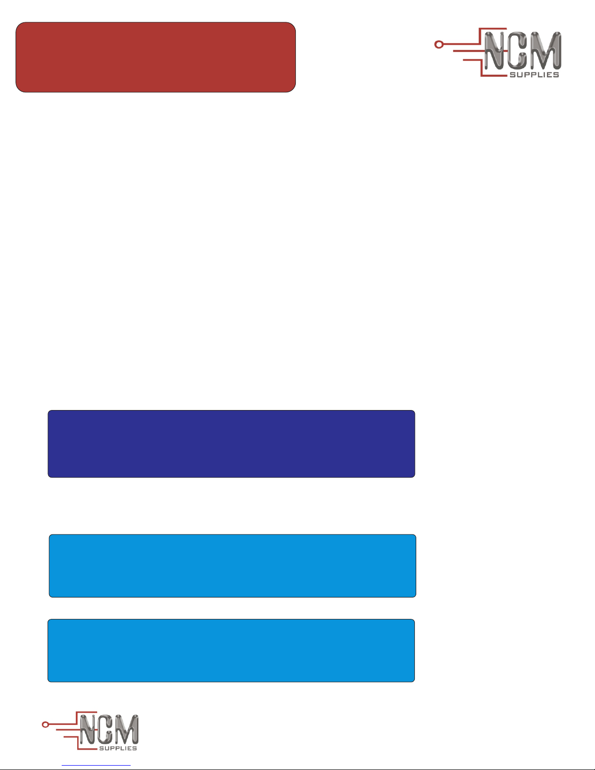
OR-200. With the Power Key off, wait until RF LED and PD LED (on front panel) blinks. Display
shows:
-The Key is closed
Please, Turn it on
6- Turn power key on. Permit the system to load. Please wait and do not turn the power key off until
monitor system starts. The NCM-OR-200 will show the following displays:
->The Key is on ...
Please Wait : 5 Seg.
NCM OPTICS
**OPTICAL-OR-200M**
MADE IN USA
8125 NW 64th Street, Miami, Florida 33166
3
Page 4
NCM Supplies Inc.
2101 N.W. 79 Ave. Miami, Florida 33122
Phone: 305-640-0461 Fax: 305-639-2684
[email protected] | www.ncmsupplies.com
NCM-OR-200
4 Channels Optical Receiver
7- When the start process finishes, the main display is shown. The main display has the status
information of the NCM-OR-200. If there is no RF alarm, then the RF LED lights up green. If RF LED
lights up red that means one or more output RF level is out of range. If no optical input alarm, the PD
LED lights up green. When optical alarm occurs, PD LED lights up red.
Status:OFF-Disable module, ON-Enable Module, ALM-Alarm in the module(FigEx: In this case RX#1is
disable(OFF), RX#2 and RX#3 are enable and work ok(ON), RX#4 is enable but alarmed(ALM)).
***While OR-200 stays on main display, it is monitoring the principal parameters of the receiver and
sends serial data via RS-232 to monitor on personal computer.
RX#1 RX#2 RX#3 RX#4
X OFF ON ON ALM
8-
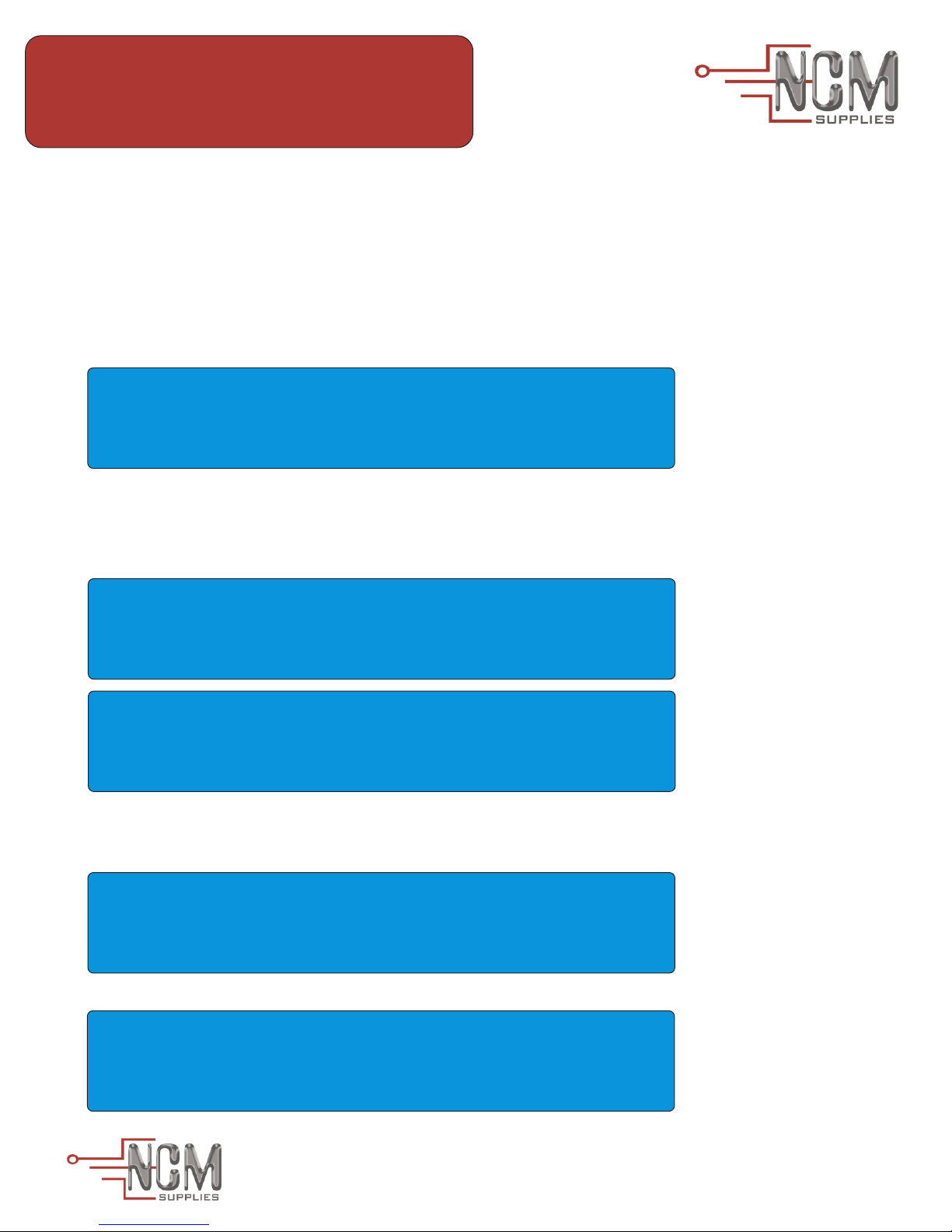
When an alarm condition is detected, you will hear a beeping sound if the sound alarm is enabled and
the main display will show a speaker symbol. An “X” symbol, if the alarm sound is disabled and you will
not hear the alarm.
GENERAL ALARM SOUND
ENABLE ^
GENERAL ALARM SOUND
DISABLE ^
9- OR-200 can disable or enable the receiver modules. Use the “R” button to find the general setup RX#x like the
picture, then change to disable or enable with “U” or “D” button. Push “R” to the next RX#x+1 display. Push “F”
to return to RX#x.
GENERAL SETUP RX#1
DISABLE ^
GENERAL SETUP RX#1
ENABLE ^
MADE IN USA
8125 NW 64th Street, Miami, Florida 33166
4
Page 5
NCM Supplies Inc.
2101 N.W. 79 Ave. Miami, Florida 33122
Phone: 305-640-0461 Fax: 305-639-2684
[email protected] | www.ncmsupplies.com
NCM-OR-200
4 Channels Optical Receiver
10- Press button “R” until you find the display “RX#x Control” like the picture below, and change the attenuator value
to modify the amplifier gain. Use “U” or “D” button to increase or decrease the attenuation.
<-- RX#1 Control -->
Attenuator 0dB ^
<-- RX#1 Control -->
Attenuator 20dB v
11- Normal operation display is located on main display. By staying in this display, OR-200 can monitor the modules.
Use “U” or “D” to measure the RF and Optical signal per module. (The second picture below displays when the
signals are not detected.)
<-- RX#1 Status -->
O: 0.2mW R: 25dBmV
<-- RX#1 Status -->
O:<0.1mW R:<20dBmV
12- To navigate from main display and to monitor the general status of the NCM-OR-200, push the “F”
button. The picture shows the general information display.(Warning: While the monitor is
navigating the serial RS-232 is stopped.)
NCM-OR-200 Ver:1.0
SN: 123456
MADE IN USA
8125 NW 64th Street, Miami, Florida 33166
5
Page 6
NCM Supplies Inc.
2101 N.W. 79 Ave. Miami, Florida 33122
Phone: 305-640-0461 Fax: 305-639-2684
[email protected] | www.ncmsupplies.com
NCM-OR-200
4 Channels Optical Receiver
13- To navigate the general monitor status on the general information display, push “U” or “D”
(Warning: While the monitor is navigating the serial RS-232 is stopped.)
+5 V Power Supply
5.0 V
-5 V Power Supply
-5.0 V
+18 V Power Supply
18.0 V
Temperature Inside
o
26.00 C
14- The next display in general monitoring depends of the installed option: 1- Fan installed, 2- TEC installed 3-
None installed(default)
Fan Current
67.00 mA
TEC Current
265.00 mA
Fan Current
No Installed
MADE IN USA
8125 NW 64th Street, Miami, Florida 33166
6
Page 7
NCM Supplies Inc.
2101 N.W. 79 Ave. Miami, Florida 33122
Phone: 305-640-0461 Fax: 305-639-2684
[email protected] | www.ncmsupplies.com
NCM-OR-200
4 Channels Optical Receiver
11- Visual alarm:
LCD backlight off and RF LED/LD LED fast blinking: NCM-OR-200 is turned off.
LCD backlight on, Power LED lights up green and RF LED/LD LED slow blinking:
NCM-OR-200 is starting up.
LCD backlight on and Power LED/RF LED/LD LED light up solid green: NCM-OR-200
is turned on and works correctly.
LCD backlight blinking and RF LED or LD LED light up solid red: NCM-OR-200 is
turned on and has alarm condition.
15- Audible alarm:
All alarm condition launch an audible alarm tone about 2000Hz,
with intervals of 500mS.
16- Critical Condition:
When the alarm conditions occurs and the system detects malfunction that may cause
damage to the PHOTODIODES, turn it off to protect the life of the PHOTODIODES.
(Warning: Contact NCM Optics for help).
17- Monitoring via RS-232 serial port:
Connect male DB9 from serial RS-232 cable into RS-232 connector on the rear panel.
Install and open the hyperterminal and configure: Bit rate: 9600bps, Data bits: 8, Parity:
None, Stop bits: 1
VENTILATION: Openings in the casing are provided for ventilation and
to ensure reliable operation of the product and to protect it from
overheating. Please, DO NOT block or cover these openings.
OR-200 should be installed in an environmentally controlled location
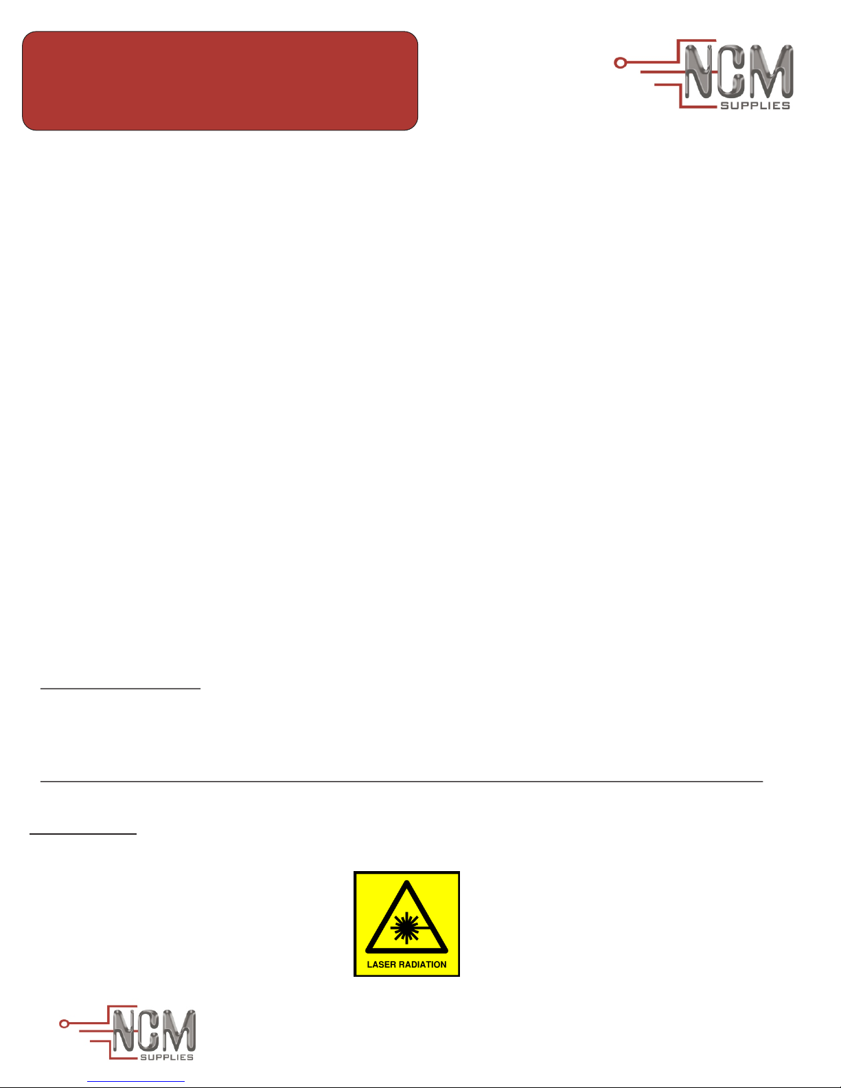
DANGER: CLASS- 3B LASER RADIATION- DO NOT STARE INTO
LASER BEAM
MADE IN USA
8125 NW 64th Street, Miami, Florida 33166
7
 Loading...