

Page 1
1
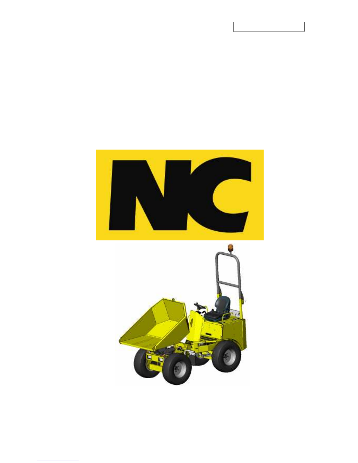
SW1.5 Site Dumper
SW1.5 Site DumperSW1.5 Site Dumper
SW1.5 Site Dumper
OPERATORS
OPERATORS OPERATORS
OPERATORS
INSTRUCTION
INSTRUCTION INSTRUCTION
INSTRUCTION
MANUAL
MANUALMANUAL
MANUAL
NC ENGINEERING (HAMILTONSBAWN) LTD
2 Killyrudden Road, Hamiltonsbawn, Co Armagh, BT61 9SF
Tel: 028 38871970 Fax: 028 38870362
email:
[email protected] www.nc-engineering.com
REVISION
ORGINAL INSTRUCTIONS
Page 2

2
Page 3

3
Dear Customer
Even if you have operated this type of equipment before, it is
very important that your new equipment operations and
instructions are explained to you by a Dealer Representative
following delivery of your equipment.
This will explain the operating controls and enable you to
gain maximum productivity from your new dumper.
Page 4

4
Page 5

5
Pre Handover Check List
Return form to
NC ENGINEERING (HAMILTONSBAWN) LTD
2 Killyrudden Road
Hamiltonsbawn
Co Armagh BT61 9SF
Delivery on this machine has been completed, including the following items.
Tick check box when each item is completed.
1. Operator Handbook delivered with equipment and operator controls and
warning labels explained to user
2. Maintenance Handbook, service intervals, fluid level checks and adjustments
explained to user.
3. Parts book and information explained (Parts book can be purchased through
dealer)
4. All items on delivery checklist have been completed
Operators signature: …………………………………………
Signature on behalf of Dealer: ……………………………...
DISTRIBUTOR/DEALER:………………
EQUIPMENT MODEL: …………………
EQUIPMENT SERIAL No:………………
HOURMETER READING: ………………
DELIVERY DATE: ……………………….
TODAYS DATE: ………………………….
Customer Name (Please Print): ………………………………………………………………
Address: ………………………………………………………………………………………
…………………………………………………………………………………………………
Postcode: …………………… Country:…………………………. Tel: ……………………...
Delivery Checklist
(Continued on reverse side)
Complete this form with the user / customer and return it to NC
At Dealership
Make sure any necessary field service instructions have been completed
Make sure all necessary certificates and literature are available
All decals are fitted
Page 6

6
At Delivery Point with Customer
Explain parts book
Explain all warning labels on equipment
Show location of all serial numbers on equipment
Lubrication & Maintenance
Explain maintenance requirements, fuel & lubricant specifications
Instruct how to use service schedules of maintenance handbook
Show all lubrication points on the equipment
Fluid Levels
Instruct how to measure all fluid levels and fill procedures
Fuel
Hydraulic Tank
Engine oil
Transmission / Power train
Coolant (inspect with engine stopped & cool)
Show Location of All Filters
Hydraulics system
Engine oil
Fuel system
Engine air
Water and Sedimentor Drains
Fuel water separator
Fuel tank drain bung
Hydraulic tank drain bung
Operation & Demonstration
Review operator handbook
Starting stopping operations
Direction change controls
Accelerator & braking controls
Warning devices (i.e. horn/ beacon)
Hydraulics controls
Legislation Awareness
Ensure the user is aware of the appropriate local, national, and international Health &
Safety Legislation for the equipment being operated
DEALER STAMP:
Page 7

7
Contents
Page No.
Declaration of Conformity
9
Noise Level Declaration
10
Vibration Declaration
11
Post Delivery Checks
12
Machine Data
14
Skip & Loading Information 14
Steering 15
Transmission 15
Brakes 15
Engine 15
Vehicle Identification Plate - VIN 15
Safety Decals and Descriptions
16
Safety Information
18
ROPS 22
Seatbelt & Seat Adjustment 23
Battery Isolator 26
Warning Others 27
Skip Prop 28
Engine Canopy
29
Driving Controls
30
Starting Procedure 31
Moving forwards & Backwards 31
Acceleration 32
Slowing Down / Stopping 32
Steering the dumper 32
Skip Control 32
Dashboard Warning Lights
33
Page 8

8
Contents
Page No.
Safe Operating Instructions
35
Visibility 36
Climbing / Descending Gradients 37
Crossing Gradients 38
ROPS 39
Transportation 40
Towing Procedure 41
Page 9

9
Engineering
(Hamiltonsbawn)
Ltd.
Manufacturers of Agricultural and Industrial Equipment
2 Killyrudden Road, Hamiltonsbawn, Tel: 028
38871970
Richhill, Co. Armagh.
Fax: 028 3887 0362
Northern Ireland. E.mail: info@nc engineering.com
8T619SF www.nc-engineering.com
EC – DECLARATION OF CONFORMITY
Machine description : Site Dumper
Make NC
Type SW1.5
Manufactured by NC Engineering (Hamiltonsbawn) Ltd
Address: 2 Killyrudden Road, Hamiltonsbawn Richhill,
Co. Armagh. BT61 9SF
This machinery has been designed and manufactured in accordance with the following European
Standards: -
2006/42/CE: Machinery Directive
Measured Sound Power Level: 98 dB LWA
Guaranteed Sound Power Level: 99 dB LWA
Net Installed Power: 17.5kW
A technical construction file for this machine is retained at the above address.
Declaration
Signed: ______________________________________
Name: David Wilson CEng; MSc; MIAgrE
Being the responsible person appointed by the manufacturer (or nominated representative of the manufacturer established in
the EC) and employed by:
NC Engineering (Hamiltonsbawn) Ltd
This declaration of Conformity complies with Regulation 22 of The Supply of Machinery (Safety) Regulations 1992
Page 10

10
Noise Level Declaration
The noise levels are measured according to ISO6395:1998
The noise level of this machine is
LWA 99dB ( A )
L
PA
82dB ( A )
LWA :- A - Weighted sound power level.
LPA :- A - Weighted sound pressure level.
Page 11

11
Vibration Declaration.
The absence of a harmonised test code together with variable conditions under which this
equipment may be used allows only representative figures to be quotes.
Whole Body Vibration Level : aw (m/s²) = 0.1
Hand / Arm : aha ( m/s² ) ≤ 3.98
The above figures are for reference purposes only. It is the responsibility of the employer to access
vibration exposure based on the actual site conditions and operating practices at the point of use.
Employers should not rely solely on published vibration figures when undertaking risk assessments.
Depending on the site conditions cycle times may need to be adjusted in order to reduce operator
exposure levels.
Page 12

12
Post Delivery Checks
•
Check the condition of the machine and make sure it has not been damaged during
delivery.
•
Tightness of wheel nuts.
•
Check the following Oil levels in engine.
Hydraulic oil and fuel levels.
Coolant level.
Battery liquid level.
Tyre pressures. (3 Bar)
The procedures for checking fluid levels can be found in the maintenance manual
If there are any faults with the machine please report them immediately to your NC dealer
representative.
On delivery of your new machine fully read this handbook:
READ THIS HANDBOOK IN FULL
Page 13
13
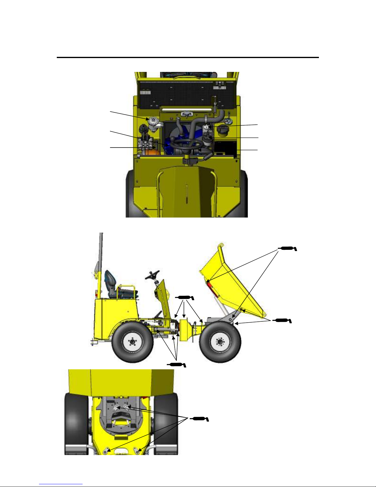
Routine Checks
DAILY CHECKS
WEEKLY GREASE POINTS
(Check each side of the dumper)
Hydraulic filter
indicator
Hydraulic oil
level
Coolant level
Fuel Sedimentor
Air filter
Engine oil level
Refer to maintenance instruction manual for
further details on the above checks.
Page 14
14
Machine Data
SKIP & LOADING INFORMATION
The dumper is fitted with a swivelling load carrying skip for transporting bulk materials
commonly found on construction sites.
CAPACITIES
Max. safe load: 1500 kg
Heaped: 815 Litres
Struck: 605 Litres
Water: 480 Litres
Never attempt to load the skip beyond its rated capacity
This dumper is basically a load carrying vehicle, that can be used for a multitude of
building/contracting site work, but essentially used to transport materials away from
excavators and other building material. The dumper will allow, if used in the correct manner
the operator to accurately place material such as soil, sand, clay, stone, debris etc. in the drop
point without damage to the material or themselves.
In the lowered or load position the skip is seated in such a fashion so that the driver has
ample view ahead. Therefore when loading the skip get off the machine and do not allow
the load to be heaped in such away that will impair view.
Before moving off on the dumper insure that the skip is fully lowered and the swivel lock is
engaged.
The following information is provided for operators for their own safety.
Stay within the safe working limits of the machine. Never attempt to use
the dumper for any task other than what it was intended for by the
manufacturer. Failure to do so could result in serious injury of DEATH.
Never Tip or Swivel The Skip Unless The Machine Is On Level Ground .
Do Not Use The Edge Of The Skip When Raised As A Dozer Blade.
The maximum distance to travel with a fully laden dumper is 1km at 15kph
To stop the tyre overheating.
Page 15
15
Machine Data
STEERING
Steering of the dumper is by an ‘Orbital’ hydrostatic steering unit, that articulates the centre
of the machine using a hydraulic cylinder which in turn gives a steering motion.
BRAKES
Braking is provided by Hydrostatic retardation. A park brake automatically engages when
the accelerator pedal is released. There is also the Park Brake Switch, this is used to stop the
vehicle in the event of an emergency.
ENGINE
This machine has a three cylinder diesel engine that transmits power to the wheels via a
hydrostatic pump and wheel motors. The dumper is equipped with electric start from a key
on the steering column. A battery isolator is provided under the bonnet in the engine
compartment.
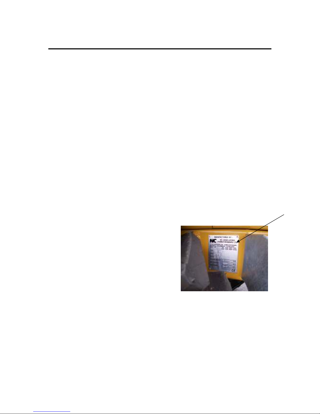
VEHICLE IDENTIFICATION PLATE - VIN
The VIN plate (A) is located on the left hand side of the rear chassis beside the steps. The
number is unique to each machine and must be quoted when in contact with the
manufacturer. From the VIN the manufacturer can call up detail relating to each individual
machine i.e. Date sold, customer, serial No., special build features etc.
(A)
Page 16
16
Safety Decals and Descriptions
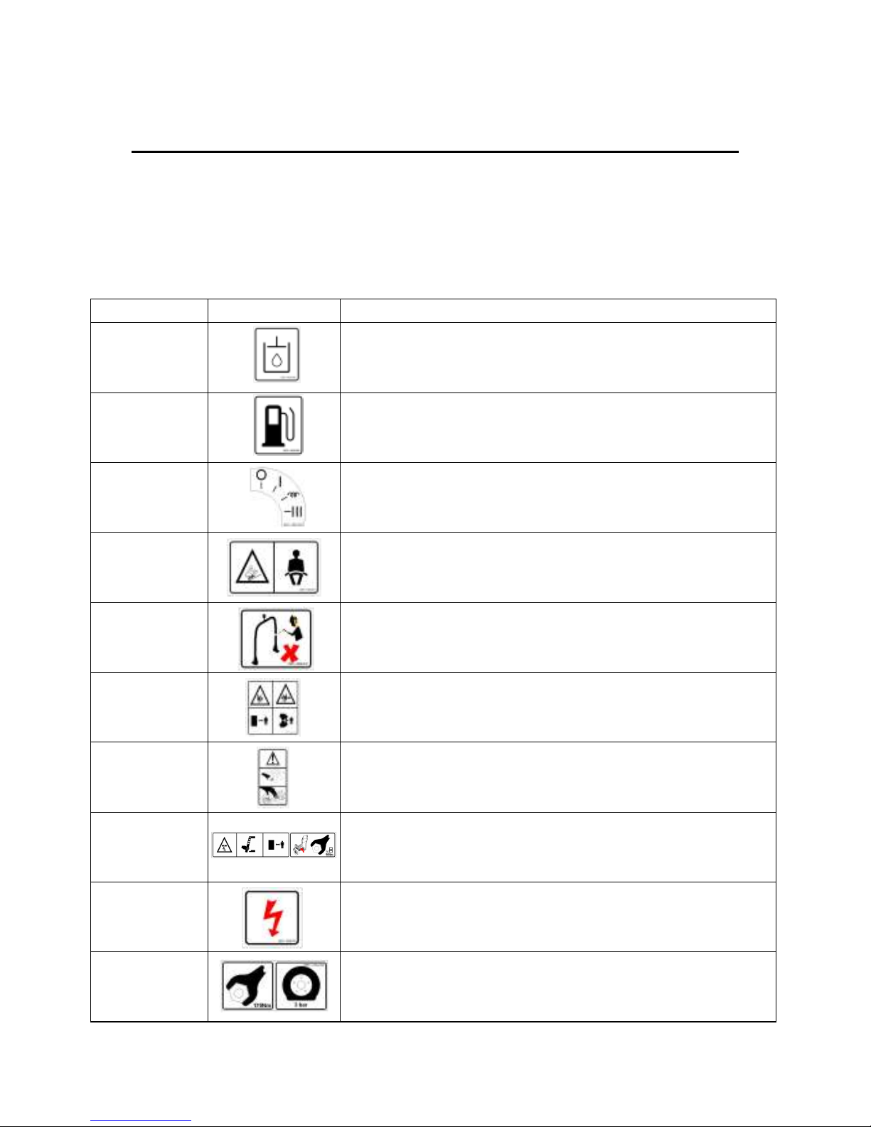
SAFETY DECALS
The Machine is fitted with a number of safety decals placed in areas to draw the attention
of the users. It is important that before using the machine theses decals are read and understood. The decals must be clean and readable at all times, if they need to be replaced
they can be obtained from NC spares department.
Part No. Symbol. Descriptions.
DEC~1920-002
Hydraulic oil.
DEC~1920-003
Fuel.
DEC~1920-010
Ignition key positions.
DEC~1920-012
Seat belt must be worn.
DEC~1920-016
No repairs to ROPS.
DEC~1920-017
Pinch points.
DEC~1920-019
Caution moving parts / Do not open when hot.
DEC~1920-078
Fit skip prop before accessing area. Tightness of turntable bolts
DEC~1920-031
Battery.
DEC~1920-032
Wheel nut torque / Tyre pressure.
Page 17
17
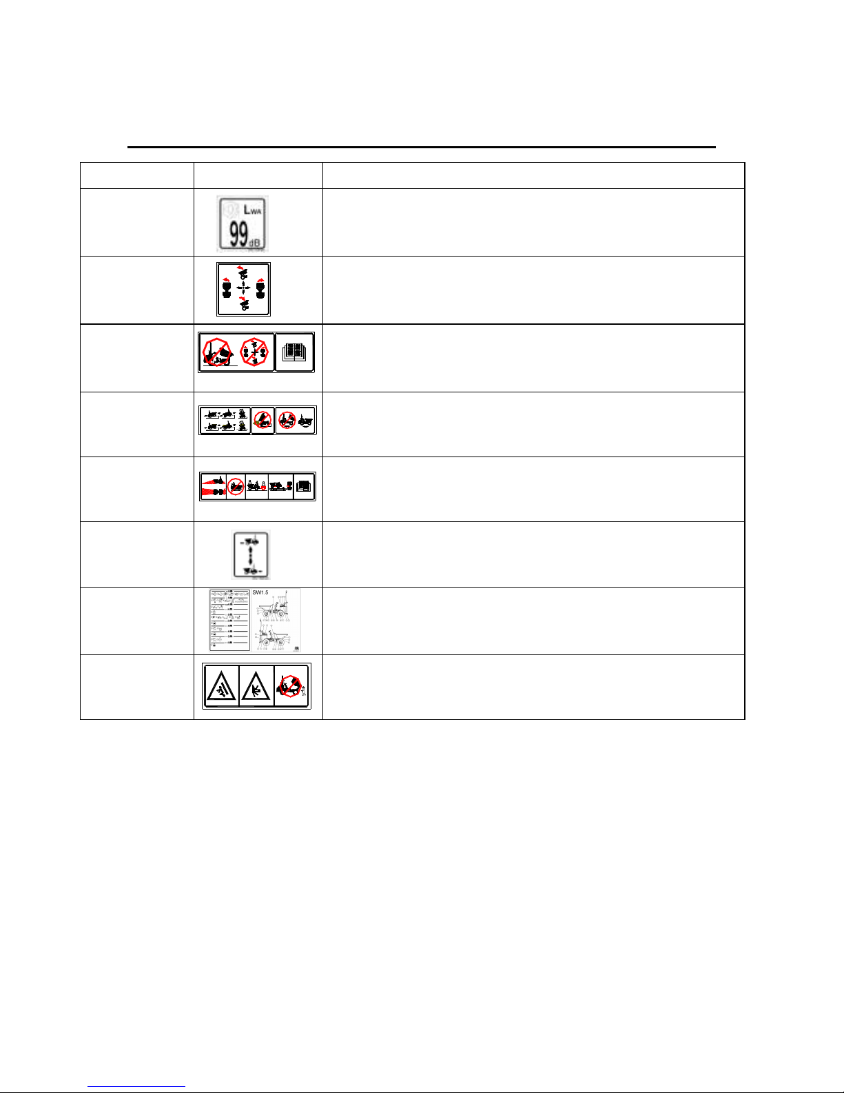
Part No. Symbol. Descriptions.
DEC~1920-033
Sound levels.
DEC~1920-005
Skip controls.
DEC~1920-013
Do not operate controls until operators manual has been read.
DEC~1920-007
Safe gradients / Don’t side tip on gradient / Lower skip before moving
DEC~1920-006
Visibility / No passengers / Towing procedures / Transport / Read manual.
DEC~1920-020
Select direction of travel
DEC~1920-079
Maintenance decal.
DEC~1920-004
Keep clear of tipping area.
Safety Decals and Descriptions
DEC~1920-005
DEC~1920-013
DEC~1920-004
5
1
20% max
4
1
25% max
1
6
16% m
a
x
5
20% max
1
16% m
a
x
4
25% max
1
1
6
DEC~1920-007
DEC~1920-006
Page 18

18
Safety Information
FOR SAFETY & PROTECTION READ THE FOLLOWING
Both operators and maintenance personnel must read the following safety
notice. The information below is given for your own safety. They must be
read before operating or carrying out any maintenance to the machine.
Local site rules must be adhered to at all times.
• Before operating the machine ensure that correct training has been given, and you are fully
conversant with the machine and its controls.
• A full training regime must be put in place for all operators to insure safe use of the machine.
• Do not operate the machine unless trained.
• All personnel must read these instructions before operating the machine. Always ensure instruction
manual is kept with the machine. If it gets lost, damaged or dirty replace it immediately.
• The decals are fitted to the machine for safety, if any become unreadable replace them with new
equivalents.
• Always ensure that the machine is run in a well ventilated area. Never run engine in a confined
space or close to flammable material.
• While refuelling the machine ensure that the engine is stopped. If fuel is split whilst refuelling take
measures to clean it up, do not restart engine until it is safe.
• The exhaust of this machine can reach high temperatures do not place objects close to it or on it.
Do not perform maintenance on a hot engine.
• Operator must be aware of all prohibited areas e.g. slopes, rough or dangerous terrain.
• Do not clean around the machine if the engine is running.
• When carrying out maintenance on the hydraulic system ensure that the oil is cool and that there is
no residual pressure in the circuit. Skin could be penetrated from hydraulic oil under pressure.
• Ensure that the operator wears all the necessary safety equipment at all times.
• Do not operate the machine if it is damaged, incorrectly adjusted or unassembled.
• To prevent an accident, place a warning sign on the machine and remove keys whilst performing
maintenance.
• When filling the skip no persons should be on the machine.
• Do not carry passengers.
• The foot plate should be kept clean from oil or dirt.
• Do not remove the coolant cap when engine is hot. Do not add coolant to the engine when hot.
• The machine should be parked in a safe position on firm level ground. Never leave the engine
running or key in the ignition.
• Before taking the machine onto the public road insure that the vehicle adheres to all road traffic
regulations. When on the road driving laws must be obeyed.
• Tyre repair must only be carried out by trained persons with the correct knowledge and equipment.
A reputable tyre firm with competent staff is recommended for this task.
• If the machine does roll over, the driver should brace themselves, hold tight to the steering wheel,
allow the seat belt to retain them and wait for the machine to come to a halt.
• If replacing parts always use parts supplied or recommended by the manufacturer. Never use parts
of lower specification.
• Always use qualified personnel to carry out repairs on the machine.
• Never over fill the engine with oil or the fuel tank with fuel.
• If the hydraulic oil level is low never start the engine.
• When starting the machine follow the instructions on the manual and on the machine.
• If oil is leaking from the machine report it and get it repaired immediately.
Page 19

19
Safety Information
This machine is designed to transport free flowing materials. If used in the correct manner it
shall provide a efficient and safe means of transport and meet all performance standards.
The operator of the machine must be an able bodied adult fully trained in its operation.
ALWAYS
•
Perform a daily check of the machine before starting.
•
Ensure instruction manual stays with the machine.
•
Check for children before starting, as they could be out of sight.
•
Have machine in neutral gear before starting.
•
Look for danger in the work area i.e. Holes, trenches, people working in confined area etc.
•
Clear obvious hazards and operate with caution.
•
Ensure visibility is clear when operating the machine.
•
Operate the machine carefully on gradients.
•
If stuck winch the machine free.
•
Wear protective clothing.
•
Wash and clean machine daily keeping water away from electrics.
•
Adjust seat to suit each driver.
•
Reduce load amount if material is of a sticky or non free flowing nature.
NEVER
•
Mount or jump obstacles such as kerbs and manholes.
•
Speed over rough terrain, always approach with caution.
•
Leave unattended the machine with the engine running this is not only dangerous but can
cause engine damage.
•
Attempt any repair to vehicle unless key is removed.
•
Tamper with any safety device on the machine.
•
Remove or tighten any hose when engine is running.
•
Start the machine unless on the drivers seat.
•
Carry any passenger.
•
Load the machine so that visibility is obstructed.
•
Overload the dumper beyond its rated pay load.
•
Fill the skip with a load that protrudes over the edge. This will block visibility, make the
dumper unstable and could cause danger to pedestrians.
•
Tip into a trench unless some one is guiding the driver in with signals to prevent the trench
giving way.
•
Move the dumper with the skip in the tip or hi-lift position.
•
Work under the skip unless supplied prop is in place.
Always use the correct fuel, oil and grease specified by the manufacturer.
Check for over head obstructions and never operate the machine unless it is safe
to do so.
Do not use the dumper other than what it was intended for by the
manufacturer.
The driver should make themselves aware to other work colleagues.
Ensure the tyres are run at the correct pressures and well maintained.
Never cross steep inclines.
Never drive the machine close to unsteady ground such as trenches, holes etc.
Page 20
20
Safety Information
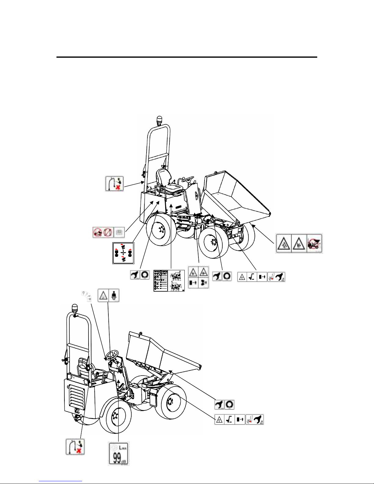
SAFETY DECALS
The Machine is fitted with a number of safety decals placed in areas to draw the attention of
the users. It is important that before using the machine these decals are read and understood.
The decals must be clean and readable at all times, if they need to be replaced they can be
obtained from NC spares department.
50
500
200
800
1000
1500
3000
DEC~1920-039(B)
HT1.5
9
1
19
171615141312
8
1
20
7
7
718
2000
21
6
16
14
1312
12
13
11
171515
12
13
11
14
1213
5
10
20
19
77
77
20
19
821186
23
11
10
9
8
5432
DEC~1920-005
Page 21
21
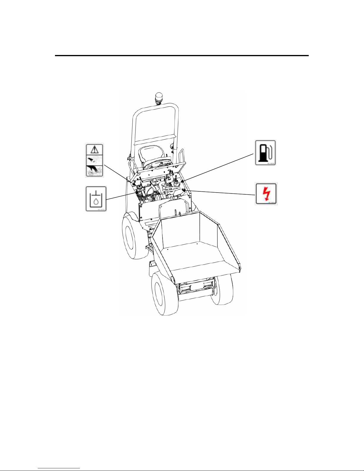
Safety Information
SAFETY DECALS
Page 22

22
Safety Information
ROLL OVER PROTECTION STRUCTURE (ROPS)
FATIGUE AND FINITE LIFE PROBLEMS WITH ROPS.
ROPS on the whole are maintenance free but in the unlikely event of a failure it is usually
due to the operator not inspecting or periodically checking the ROPS for cracks, loose bolts,
damage or other normal wear and tear. Proper maintenance and routine checks of the ROPS
on the machine will insure lifesaving function and long life of the system.
FACTORS THAT LEAD TO MISUSE OR DAMAGE TO ROPS
•
Vibration can cause structure damage and/or when loading in some instances.
•
A corrosive environment.
•
Continued use of the ROPS after a roll over causing damage to the structure.
•
Unauthorized Modifications to the ROPS.
•
Mount fatigue.
•
Replacing bolts with the wrong grade or wrong torque setting.
•
Incorrect installation.
ATTACHMENT AND/OR MODIFICATIONS
ROPS are not intended as a load carrying member and should not be used to mount things
such as, pull hooks, winches, booms, etc. Non load bearing attachments such as mirrors,
fans, heaters, lights, etc. can be installed using manufacturers guidance.
REPAIR & MAINTENANCE
•
Water drainage holes should be kept free from dirt or blockages so that water does not get
trapped and freeze damaging the structure.
•
Paint peeling or corrosion on the ROPS should get immediate attention.
•
Replacement of the ROPS or mounts should be done in a professional way, replace worn
bolts and re-torque to correct settings.
Page 23
23
Safety Information
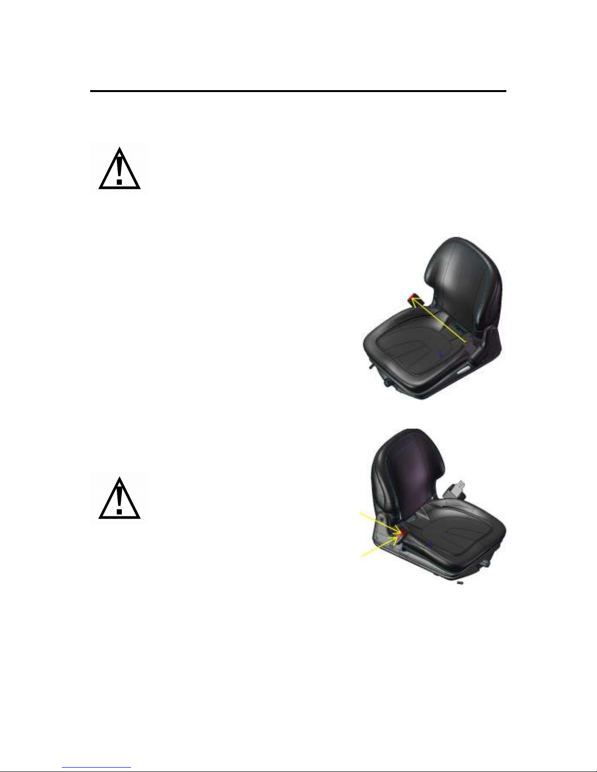
SEAT BELT INFORMATION
•
Improper inspection of the seat belt could cause serious injury or loss of
life in the event of an accident.
•
In the event of an accident the entire seat belt system must be replaced.
•
If needed the seat belt must be replaced throughout the life of the
machine. The belt must get inspected at least once a year or more often
if the belt is exposed to harsh conditions.
•
If the seat belt shows signs of wear it is vital that the entire belt both
sides are replaced.
Before operating the machine it essential that all drivers
put on the seat belt.
To fit the seat belt correctly, pull the belt around your
waist and press buckle blade into buckle lock.
Pull belt webbing through buckle blade to remove slack.
The seat belt must be correctly adjusted every time.
If the belt is worn loose in the event of an accident or roll
over it may cause serious injury.
To release the seat belt press either of the red buttons on
the buckle lock and allow the seat belt to fully retract.
Buckle up it could save your life.
NOTE:
Keep the buckle area clean and dry. Dirt and other foreign items can gum up the works and
prevent your belt from buckling correctly, thereby weakening its ability to hold you firmly in
place during an accident or roll over.
If your seat belt does get dirty and needs cleaning use mild soap and warm water. Do not
use a strong detergent, bleach or dye, since these caustic fluids may weaken the belt's
material.
Page 24
24
Safety Information
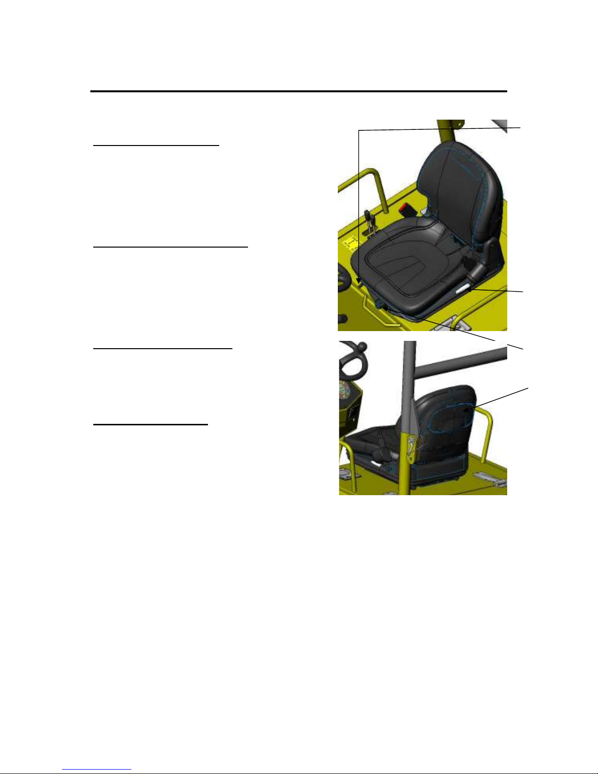
SEAT ADJUSTMENT
WEIGHT ADJUSTMENT
The seat can be adjusted for weight by screw knob
(A). To add more compression to the seat for a heaver
person turn the knob (A) clock-wise and anti-clock
wise for a lighter person. The seat ranges from
weights of 50kg-130kg and the desired weight can be
acquired be turning knob (A).
HORIZONTAL ADJUSTMENT
The seat can be adjusted horizontally fore and aft
direction by pushing the lever marked (B) and sliding
the seat back or forward to the required position so
that the operator has full control of the foot pedals and
steering column. When the lever is released the seat
will lock into place.
BACKREST ADJUSTMENT
For more comfort the operator can adjust the back rest
by lifting the lever (C). The seat backrest will move
through an angle of 17.5° to accommodate every
operator.
DOCUMENT POCKET
On the backrest of the seat a document pocket (D) can
be found. In the pocket this manual should be stored
and any other documentation that must be kept with
the machine. Keep the lid closed to avoid rain water
penetration into the documents.
(A)
(C)
(B)
(D)
Page 25
25
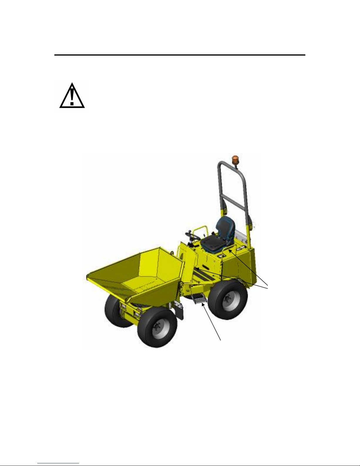
When mounting or dismounting the dumper, the grab handles provided
must be used to retain balance. Grab handles are mounted on both sides of
the dumper and must be used in conjunction with footsteps provided.
Never attempt to use the steering wheel, control levers or forward - reverse
lever for assistance.
ALWAYS USE GRAB HANDLES
Grab handles
Steps
Page 26
26
Safety Information
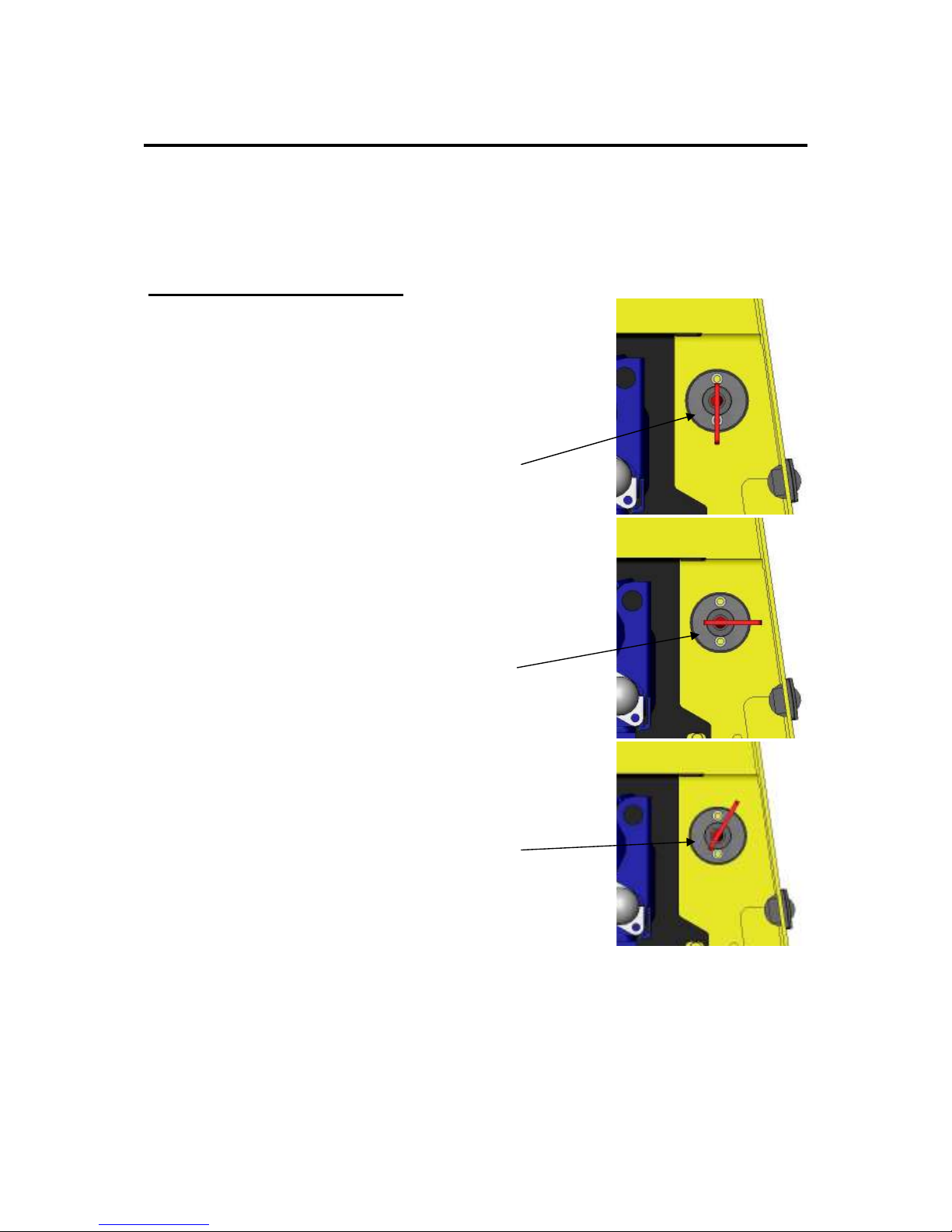
BATTERY ISOLATOR
The battery isolator is to be used when ever maintenance is being performed on the machine
to stop accidental engine start up. The isolator switch can also be used in the event of long
periods of the dumper being unattended e.g. meal breaks, overnight etc. This will prevent
vandalism and use by unqualified site workers.
HOW THE ISOLATOR WORKS
When the handle of the isolator is in position (A) it is active. By
turning the handle anticlockwise through 90° to position (B) this
will totally isolate the battery from the electric circuit. By turning
the handle a further 45° to position (C) you will be able to
remove the handle for security purposes.
(A)
(B)
(C)
Page 27
27
Safety Information
WARNING OTHERS
The dumper is fitted with a number of devices to warn others nearby of impending danger
from the machine.
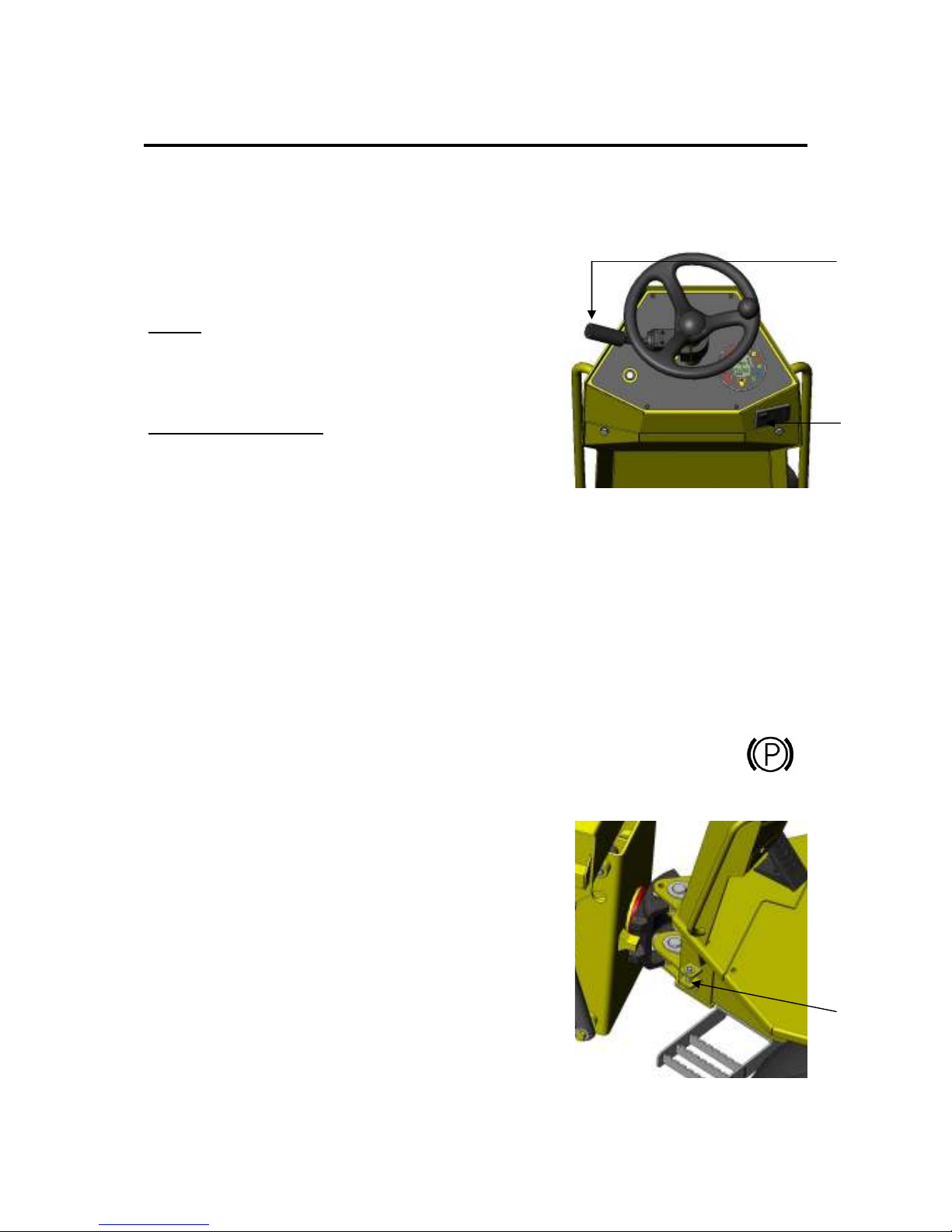
HORN
The horn can be activated by pressing the button on the
end of the FNR lever (A) Once the button is released the
horn will stop.
REVERSING ALARM
This is activated automatically when reverse is selected
on the FNR lever (A).
PARK BRAKE
A park brake switch is fitted to the steering column, this can be used as a secondary stopping
action if in emergency. This will stop quickly as transmission is put into neutral and drum
brakes in rear wheel motors are applied simultaneously.
The park brake is automatically applied in any of the following conditions
•
The FNR lever is in the neutral position
•
The ignition switch is off
•
The park brake switch is applied
•
The foot accelerator pedal is fully released.
A indicator light will illuminate red on the display when the park brake is applied
CHASSIS LOCK
Ensure the chassis lock pin (C) is disengaged before
moving the dumper. It should be stored as shown with the
“R” clip in place.
Failure to check will prevent the dumper from steering in
the desired direction and may damage the cast swivel block.
(A)
(B)
(C)
Page 28
28
Safety Information
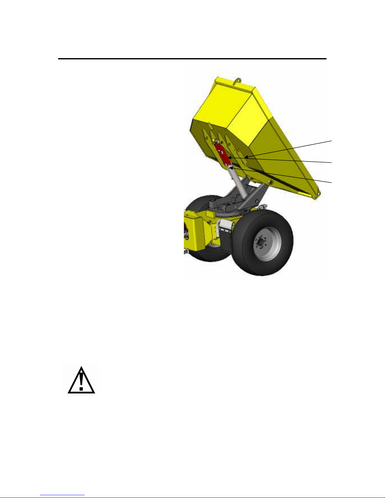
SKIP PROP
•
Ensure the dumper is parked in a
straight position on firm level
ground in an area that it will not
cause an obstruction to others.
•
Put the FNR lever to the neutral
position.
•
When the engine is running, tip the
skip by pushing forward on the
lever.
•
Remove the ‘R’ clips from the safety
prop pin stored in position (A) and
fit prop around the ram rod in
position (B). Insert pins (C) and fit
R clips
clip to secure in position. Lower the
skip gently until it stops.
(A)
(B)
(C)
If the pins, folded channel or “R” clip become lost get replacements from
NC. Never use a substitute prop or work under an un-propped skip.
Pin part number: SD0160-02A
Folded channel part number: SD0160RA
ALWAYS LOCK THE PROPS IN POSITION WITH PINS & R CLIPS
Page 29

29
Engine Canopy
OPENING
Access to the engine area is gained by lifting the
engine canopy upwards. This is done by:
•
Ensure lock (B) of handle (A) is unlocked.
•
Pull handle (A) to release the canopy latch.
•
Lifting the canopy, using handle (C).
The gas strut (D) will hold the canopy in the raised
position.
CLOSING
•
Pull the canopy down and firmly push closed using
handle (C) ensuring the canopy latch closes around
the striker bar.
•
Ensure the lock (B) for handle (A) is locked to
prevent unauthorised access to the engine.
(A)
(B)
(C)
(D)
Page 30
30
Driving Controls
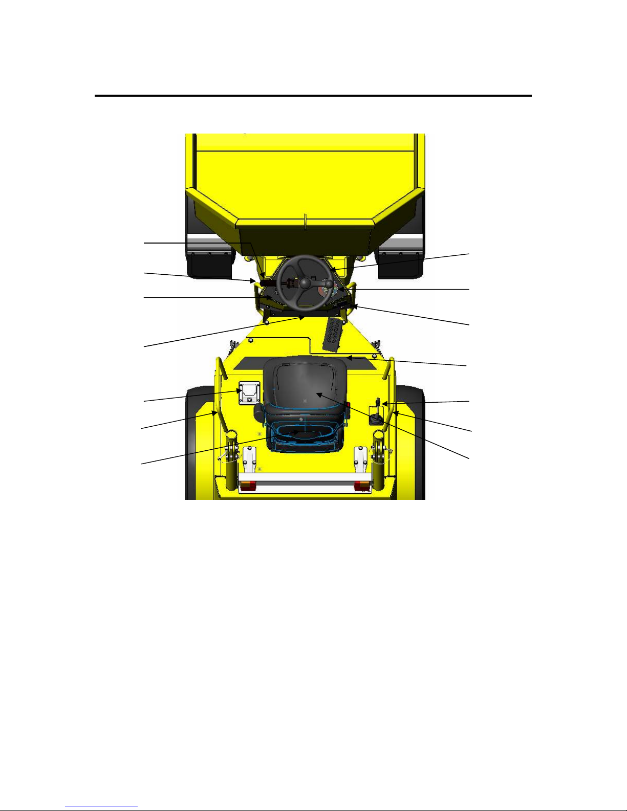
LAYOUT OF CONTROLS
1. Steering wheel
2. Instrument display
3. Park brake switch
4. Accelerator pedal
5. Hi-lift control lever
6. FNR lever
7. Horn
8. Ignition switch
9. Fuse & relay box
10. Engine cover latch
11. Grab handles
12. Seat
13. Documents pouch
(1)
(2)
(3)
(4)
(11)
(5)
(12)
(7)
(8)
(10)
(9)
(6)
(11)
(13)
Page 31
31
Driving Controls
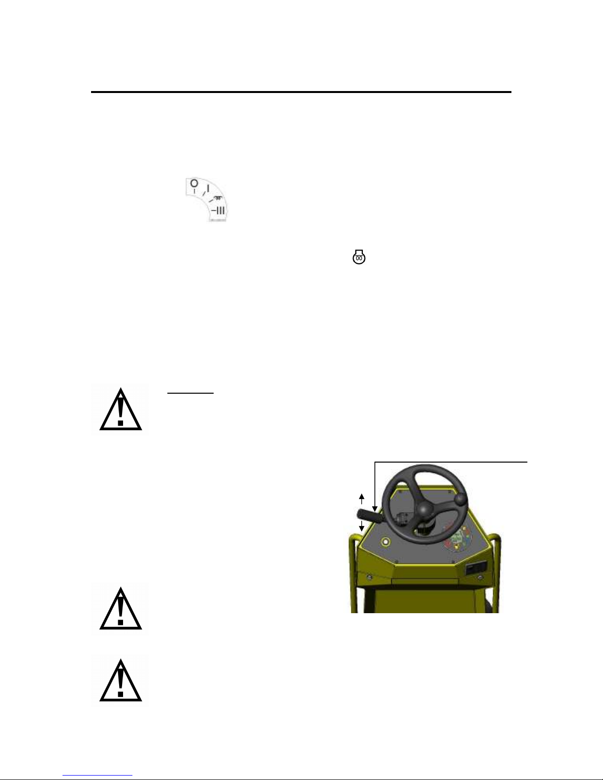
STARTING PROCEDURE
Ensure neutral is selected on the FNR lever. The engine will not start if the FNR selector
lever is in either forward or reverse. Check the Isolator is in the ON position.
The starter switch has four stages
1. Off
2. On
3. Engine Heat
4.
Engine Start
To start the engine turn the key clockwise to the pre-heat position and hold, the pre-heat
symbol on the instrument display will illuminate orange.
When the pre-heat light goes off turn the key to the Engine Start position. The starter motor
will be engaged and the engine will begin to crank.
If the engine does not start within 15 seconds return the key to the off position and leave the
engine another 2 minutes before reattempting to start again.
When the engine fires release the key and the spring will automatically return to the on
position. Always ensure the key springs back from the cranking position, if the key sticks in
the cranking position the starter motor will be damaged.
TO MOVE FORWARD/BACKWARDS
Push the FNR lever (A) in the desired direction of
travel.
If reverse is selected the reversing bleeper will
automatically start sounding
Warning: Do not keep accelerator pedal fully
depressed when the engine has started, do not race the
engine until the oil pressure warning light goes out.
When stopping the engine always allow the revs to return naturally to idle
before turning the ignition switch to off. This will ensure all rotating parts
have slowed down and will not be starved of oil.
(A)
F
R
When changing direction always allow
the dumper to stop before engaging
opposite direction
Page 32
32
Driving Controls
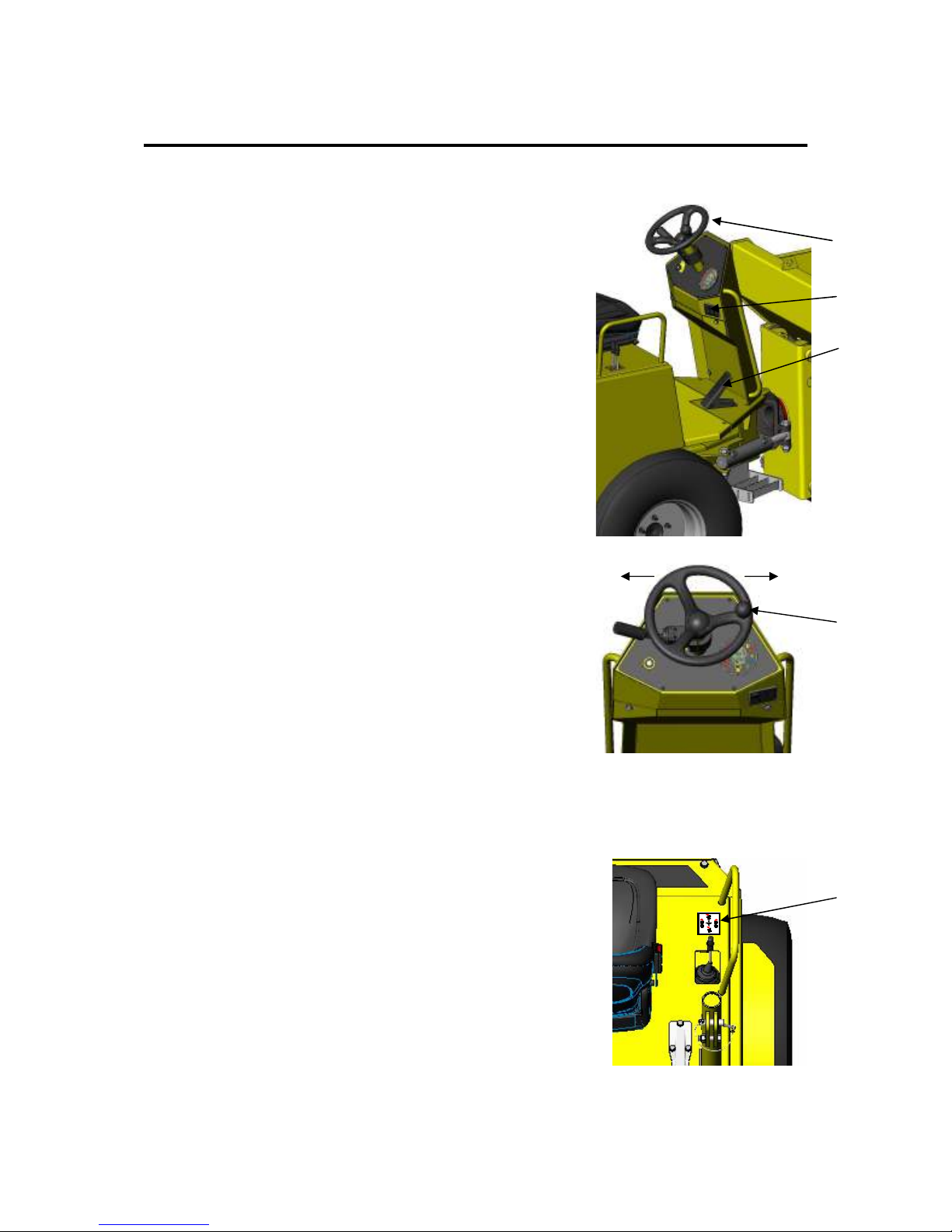
ACCELERATION
To make the dumper go faster depress the accelerator pedal
(A) with your right foot , this will increase the revs of the
engine.
SLOWING DOWN / STOPPING
To slow down remove your foot from the accelerator pedal,
this will automatically slow down the dumper.
(When the accelerator pedal is fully released the park brake is
applied)
EMERGENCY PARK BRAKE
Emergency stopping, the dumper will retard to stop normally
when the accelerator pedal is released. Using the Park Brake
Switch (B) will stop the dumper more quickly. The rate of
deceleration will be increased over the normal slowing down
as the power to the forward and reverse solenoids is removed
effectively putting the dumper into neutral and the engaging of
the brake pads in the rear wheel motors.
TO STEER THE DUMPER
Use steering wheel (D) to control direction of vehicle from left
to right (operate steering wheel with hands only). The vehicle
pivots about the centre of the machine.
If using the knob on the steering wheel ensure the non steering
hand is holding on the grab-rail on the engine cover
SKIP CONTROL
Use the levers to the right hand side of the seat to control the lifting and swivelling of the
skip.
•
To tip the Skip, push the lever to the front.
•
To return the Skip to the loading position pull the lever to
the rear.
•
To rotate the skip; tip the skip slightly to lift it out of the
lock and pull the lever to the desired direction.
This is indicated on the yellow sticker (E)
(A)
(B)
(C)
(D)
L R
(E)
DEC~1920-005
Page 33
33
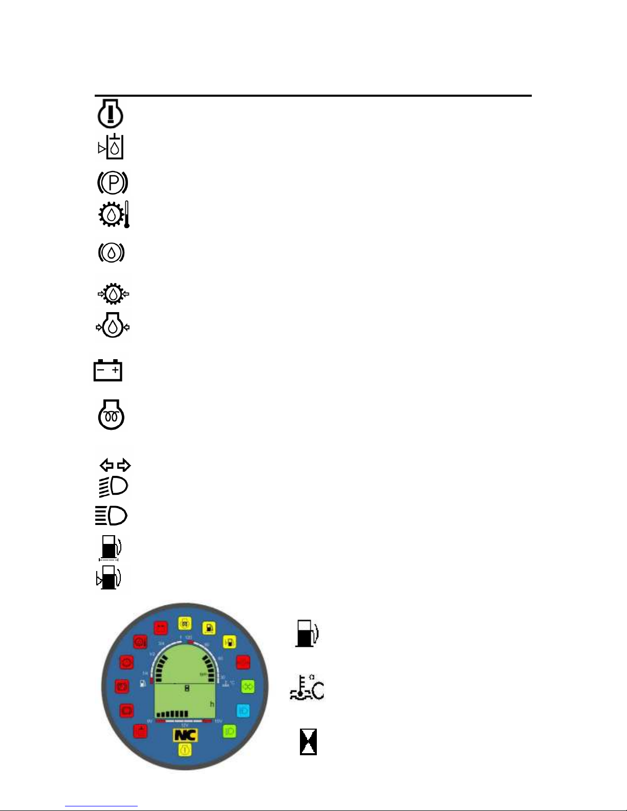
Dashboard Warning Lights
Attention (Not Applicable To This Dumper)
Engine failure / Malfunction .
Low Hydraulic Oil (optional)
If hydraulic oil drops below a minimum level this light will illuminate. Dumper
should be filled to the correct level before continuing with work.
Parking Brake
This light will stay on when ever the park-brake is applied.
Transmission Oil Temperature (Not Applicable To This Dumper)
If the transmission oil reaches a temperature deemed not suitable for operation this
light will glow.
Low Brake Fluid (Not Applicable To This Dumper)
Indicates if brake fluid is below minimum level, top up immediately or brake failure
may occur.
Transmission Oil Pressure (Not Applicable To This Dumper)
If the transmission oil pressure drops below a limit value this light will illuminate.
Engine Oil Low Pressure
If the engine oil pressure drops to a preset pressure this symbol will light, engine
should be stopped to prevent damage.
Battery
When this light comes on there is a fault with the battery charge system, i.e. broken/
slipping fan belt etc. The battery voltage condition is also displayed under the hours
gauge.
Pre-Heat
When the key is turned to the engine heat stage this light will illuminate to show
the operator the glow plug is working. It will go out when the pre-heat is complete.
The engine should then be cranked
Indicator (optional)
If fitted the turn signal switch will make the indicator repeater symbol will light.
Dipped Beam (optional)
Shows the operator if dipped beam is applied when road lights are fitted.
Main Beam (optional)
Shows the operator if main beam is applied when road lights are fitted.
Fuel Filter (Not Applicable To This Dumper)
When this symbol is illuminated the fuel filter has been contaminated with water.
Fuel Level
This symbol will illuminate when the fuel level goes below a certain level to warn of
running out of diesel.
Fuel Gauge
If all the segments are illuminated on the
bar graph the fuel tank is fuel. This
indicates fuel level in the tank.
Water Temperature
If the level goes into the red, stop the
dumper immediately and check coolant,
refer to maintenance manual regarding
overheating.
Hour Meter
Records total time machine is used.
Page 34

34
Dashboard Warning Lights
PRECAUTION AGAINST OVERHEATING
Take the following actions in the event that the coolant temperature is nearly or more than
boiling point, what is called “overheating” Take these actions if the LED’s on the bar-graph
go into the red zone (A)
1. Let the dumper idle in a safe place
2. DO NOT stop the engine suddenly. Stop it after
about 5 minutes of unloaded idling
3. If the engine stalls within 5 minutes of unloaded
idling. Immediately leave the area and keep a safe
distance from the machine. DO NOT lift the
engine cover
4. Keep yourself and others at a safe distance for 10
minutes or while steam is blown out.
5. Checking that there is no dangers such as
possibility of burns. See the Fault finding section
of the maintenance manual Chart D2
(A)
Page 35

35
Safe Operating Instructions
VISUALLY CHECK MACHINE
1. Ensure chassis lock is disengaged.
2. Ensure controls and hydraulic rams are clean and free of debris.
3. Check ROPS frame is upright, secure and not damaged.
4. Seat belt is safe and secure and locks into place.
5. All covers and mudguards are securely bolted down
6. All hoses are free from fluid leaks
7. All safety decals are legible.
8. The tyres are free from cuts or splits.
9. All bolts / nuts are in position and tight.
10. Daily maintenance checks have been preformed. (see maintenance manual).
MOUNT MACHINE & CHECK CONTROLS
1. Use the grab-rails and steps provided to mount the machine
2. Ensure the engine cover is secure and locked.
3. Adjust the seat to your user preference.
4. Fasten the seat belt around your waist and adjust to suit for safety your comfort.
5. Ensure the dumper’s FNR lever is in neutral.
6. Do not operate this machine unless you understand the controls and warning lights on
the instrument display panel.
REPORT ALL FAULTS IMMEDIATELY
Page 36
36
Safe Operating Instructions
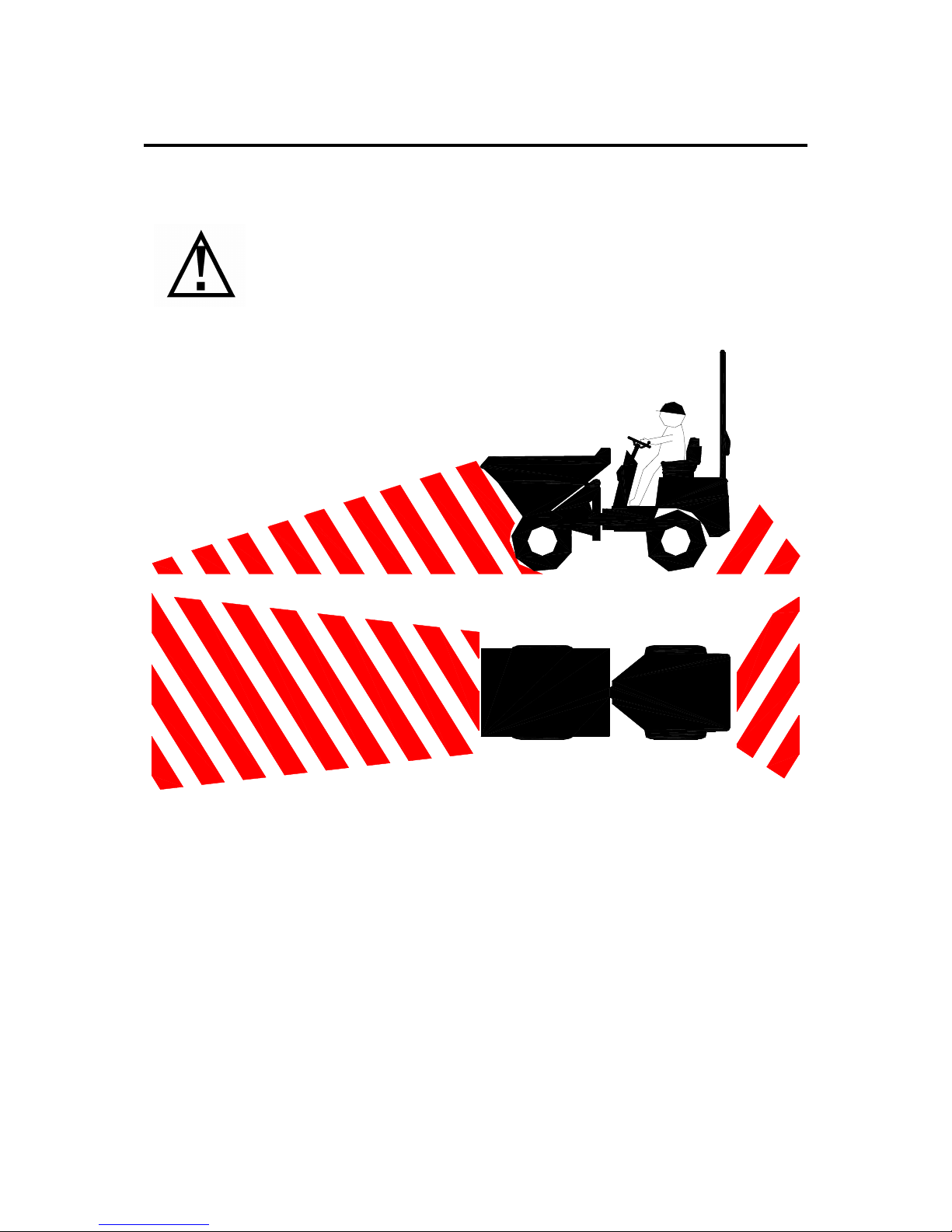
VISIBILITY AROUND DUMPER
Take care when driving the dumper. Before moving off always ensure there
are no persons in areas of low visibility. Sound the horn to warn others of
your approach. Don’t move off until you are sure no persons are obstructing
your path. If in doubt stop and check around the dumper and clear any
obstructions form your path.
NOTE: Diagonal shading represents areas of reduced visibility.
Page 37
37
Safe Operating Instructions
CLIMBING / DESCENDING GRADIENTS
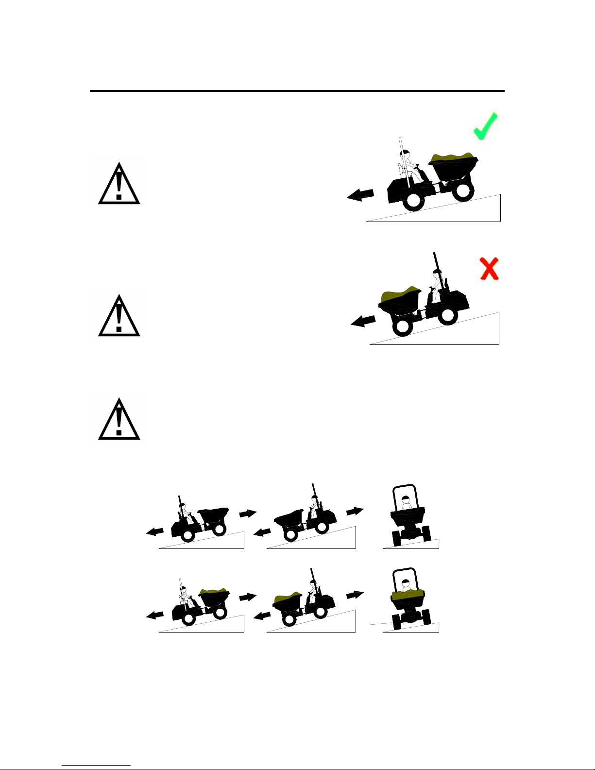
DO NOT exceed the maximum stated GRADIENTS to avoid serious injury or DEATH
Always reverse down steep inclines.
ONLY fill the skip with free flowing
materials.
Avoid driving down gradients if
possible. Use the brakes softly as sudden
sharp braking will induce weight
transfer on to the front wheels and may
cause stability issues.
When ascending or descending a gradient, especially when the skip is loaded,
the skip MUST ALWAYS face the incline.
NEVER EXCEED THE MAXIMUM STATED GRADIENTS.
5
1
25% max
20% max
4
1
5
1
20% max
4
1
25% max
1
6
1
6
%
m
a
x
5
20% max
1
1
6
%
m
a
x
4
25% max
1
1
6
Page 38
38
Safe Operating Instructions
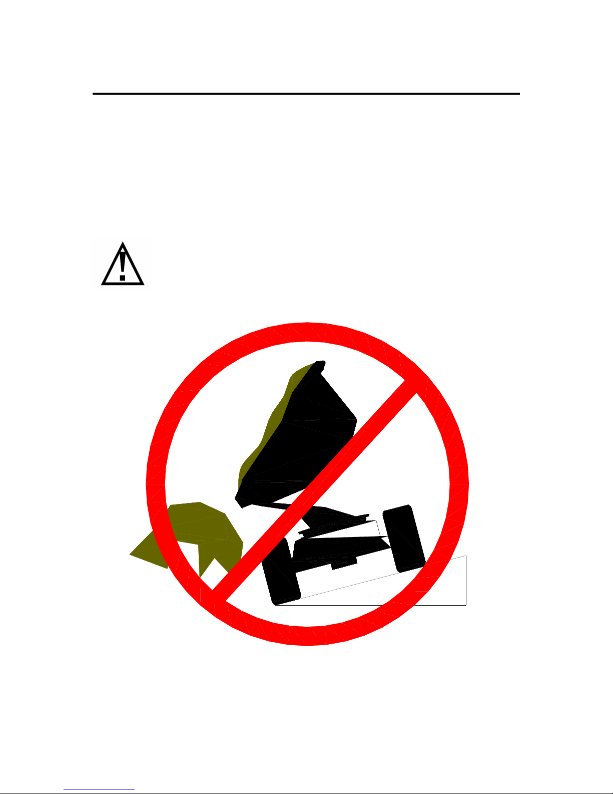
CROSSING GRADIENTS
Muddy slippery ground conditions will effect the ascending and descending capabilities of
the machine. Special care must be taken when crossing gradients with these conditions to
prevent the dumper sliding side ways and out of control of the operator.
DO NOT Drive across sloping surfaces with the skip raised Machine could
tip causing injury or death.
Page 39
39
Safe Operating Instructions
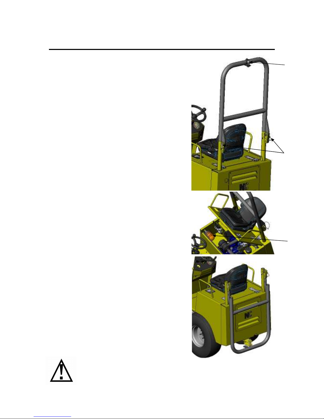
ROPS BAR
The dumper is fitted with a folding ROPS bar, which can
be lowered for transportation purposes.
LOWERING
•
Remove beacon from (A) and put in storage
position under the engine cover.
•
Remove the Linch Pins from the pins (B).
•
Remove the pins (B).
•
Lower the ROPS until it is seated firmly.
•
Reinsert the pin to keep it safe.
RAISING
•
To raise the ROPS bar reverse the above steps.
MAINTENANCE
•
Check the pins are free and undamaged.
•
Regularly grease the pins to ensure they can be
removed easily.
Only lower ROPS when transporting on a trailer/lorry.
NEVER operate the dumper with the ROPS bar lowered as this could result
in serious injury or DEATH.
(A)
(A)
(B)
Page 40
40
Safe Operating Instructions
USING THE DUMPER FOR TOWING LOADS
This dumper is not designed as a towing vehicle, but if the machine has to be used for
towing an implement make sure the weight of any trailer and its load does not exceed half
the rated payload of the dumper. It is important that if the dumper is used as a towing vehicle
the skip is half loaded to give equal brake balance on both axles. Never tow on steep
gradients as “Jack Knifing” could occur.
TRANSPORTATION
LOADING
If the dumper has to be loaded onto a lorry or trailer, strong loading ramps should be used to
support the weight of the machine, see technical data for dumper weight.
RAMPS
•
When loading the dumper onto a lorry or trailer the wheels must be chocked if necessary.
•
For loading the dumper the angle of the ramp must not exceed the grade-ability of the
machine, in wet slippery conditions the loading angle may need to be less.
•
When loading the dumper onto a lorry or trailer it is recommended that a winch is used to
propel the machine up the loading ramps. The brakes will need to be released in the rear
wheel motors. Also the hydrostatic pump needs to be by passed, refer to next page. To
attach the winch to the dumper use a two legged chain attached to the correct tying points
at the front of the machine (A).
•
Secure the dumper to the lorry chassis using chains, straps or ropes capable of holding the
machine, attached to the lashing points on the dumper.
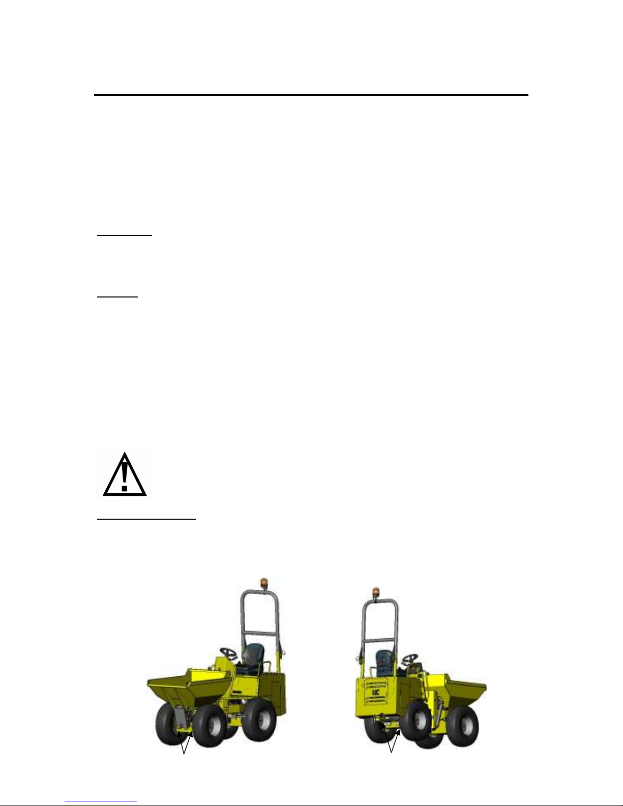
LASHING POINTS
Lashing points (A) and (B) in the picture below should be used to tie the machine to a lorry
or trailer bed. These points are on either side of the dumper. They can also be used to tow
the vehicle, i.e. onto a transporters etc.
Grade-ability Will Be Reduced In Wet, Muddy, Oily Conditions.
Lifting The Machine To Load Is Not Recommended.
(A)
(B)
Page 41
41
Safe Operating Instructions
TOWING PROCEDURE
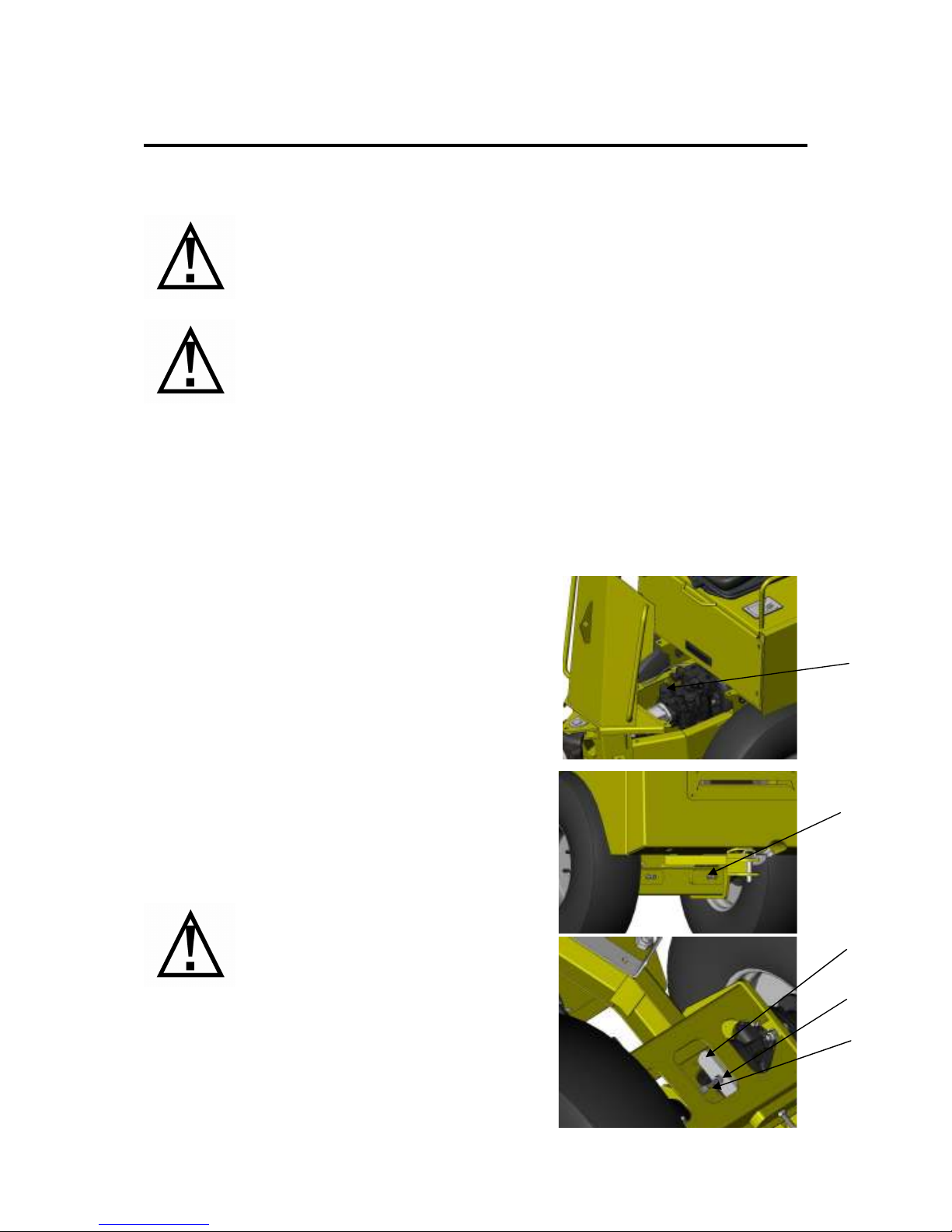
OPENING THE HIGH PRESSURE CIRCUIT
•
Unscrew bypass valve (A) by 2 turns
RELEASING PARKING BRAKES
•
Remove the blocks (B) from the rear axle
•
Remove & dispose of the rubber plug from the
brake protector .
•
Place the 25mm steel flat over the drum.
•
Tighten the bolt (C) to the bottom of the threading
in the wheel motor.
•
Tighten the nut (D) until the motor shaft turns
freely, while holding the screw.
•
After releasing always insert a new rubber plug.
IMPORTANT: In some countries it may be illegal
to tow the dumper. It is your responsibility to
know the law in your own country
The dumper may only be towed using suitable towing equipment such as a
towing bar or cable. These must be fixed to either the towing hitch
(optional) or the tying down eyes at the front or rear axle.
The dumper may only be towed when the following steps have been
carried out. Failure to observe these tasks will invalidate any remaining
warranty and seriously damage the hydrostatic drive pump and wheel
motors.
•
Open the high pressure circuit on pump
•
Parking brakes released on both wheel motors
•
Max Towing speed: 2 Kmph
•
Max towing distance: 1 Km
Ensure the dumper is on a level
surface and that the wheels are
chocked to prevent it rolling away.
(A)
(B)
(B)
(D)
(C)
 Loading...