

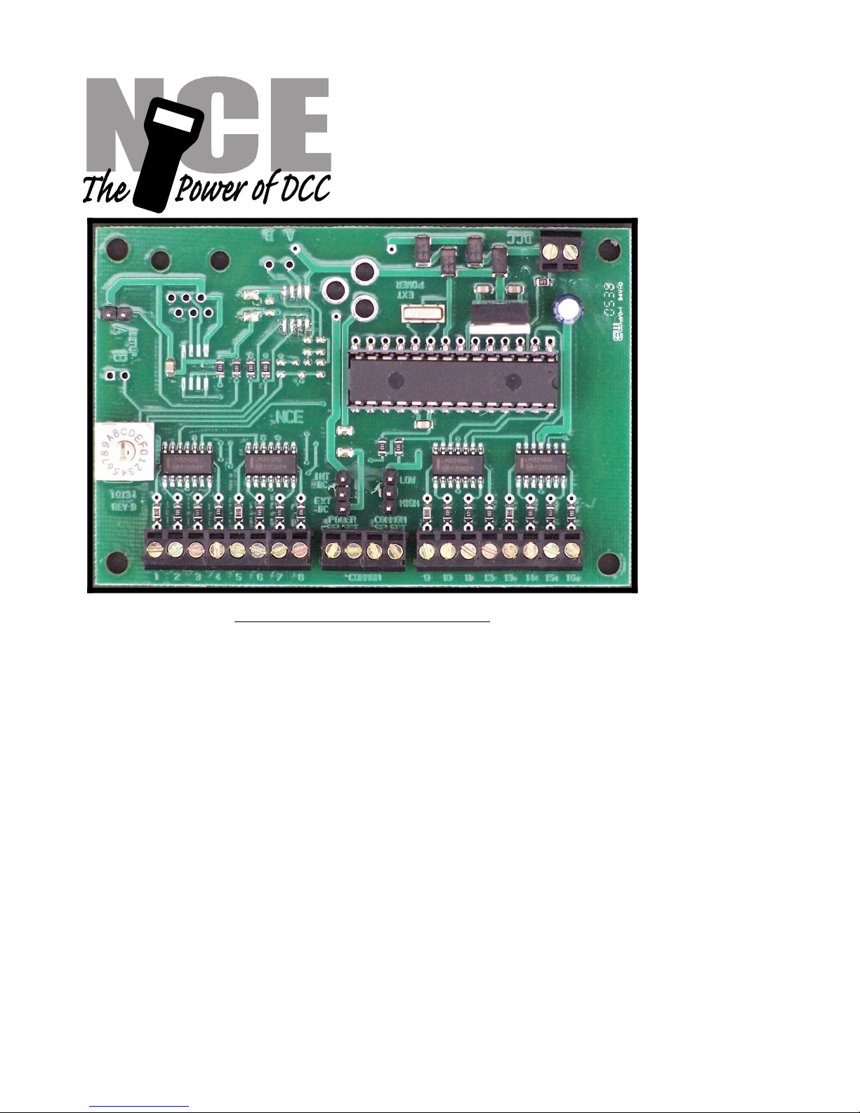
SWITCH-8
Accessory Decoder
FOR STALL MOTOR MACHINES ONLY
NOT FOR USE WITH TWIN COIL SWITCH MACHINES
Decoder revision A
$59.95
EASY PROGRAMMING!
‚ Control for 8 TortoiseTM switch machines
‚ SWITCH-8 remembers the position of switch during power outages
‚ Switch-8 supports the full range of DCC accessory addresses (1-2044)
‚ Easy address programming, no need to connect it to programming track
‚ Each switch machine can have its own completely different address
‚ Simple hook up, 2 wires to the track, 2 wires to each switch machine
This book, schematics and artwork copyright 2000-2006
NCE Corporation 899 Ridge Road Webster, NY 14580
Switch-8 is a trademark of NCE Corporation
05240136
05240136
Last revised: 8 November 2006
Notes:
This decoder is designed to control Tortoise, SwitchMaster or other low current "stall
motor" switch machines. The outputs are rated for 50mA maximum. Most Tortoise
machines draw 10 to 20mA with normal track voltage (about 13-15 volts). There are
four mounting holes at the corners of the Switch-8.
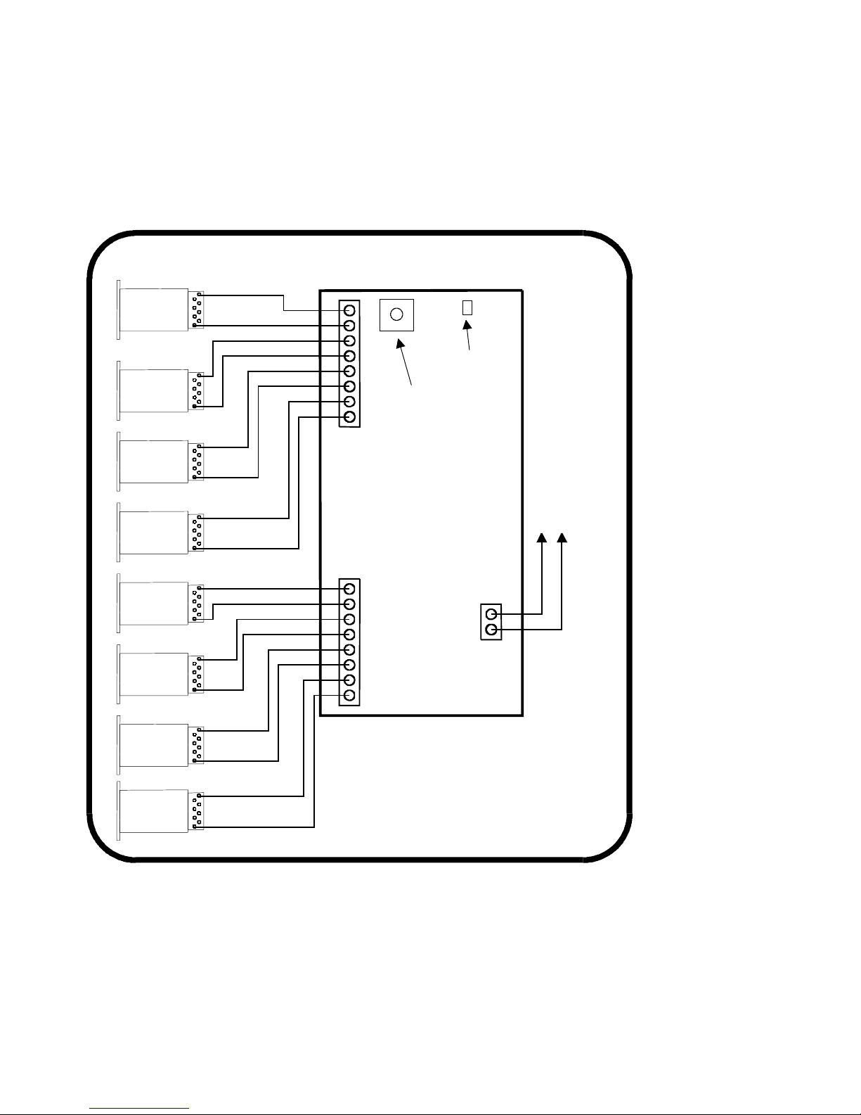
Wiring:
See the diagram below for wiring particulars. The only required wires are two wires to
the track and two wires to each machine. It is OK to use the Switch-8 for control of less
than 8 machines.
Switch machine mounting tip:
On our Tortoise machines we use hot glue to mount the machine. The glue stays
liquid just long enough after application to allow alignment of the machine. We
manually center the arm of the machine then slide the machine around while the glue
sets to align the points to the middle of their throw. The low temperature hot glue is
weak enough to allow removal of the machine later on by prying with a putty knife.
Use a throw wire that is about 6” (150mm) longer than the one provided with the
Tortoise to give you room to put glue on the machine after the wire is put through the
roadbed.
Last revised: 8 November 2006 Page2
To Track
Tortoise Machines
Illustrated on left
SWITCH-8 wiring diagram
TM
Rotary Switch
Setup Jumper

Factory default values for decoder
Outputs 1&2 factory programmed to accessory address 1
Outputs 3&4 factory programmed to accessory address 2
Outputs 5&6 factory programmed to accessory address 3
Outputs 7&8 factory programmed to accessory address 4
Outputs 9&10 factory programmed to accessory address 5
Outputs 11&12 factory programmed to accessory address 6
Outputs 13&14 factory programmed to accessory address 7
Outputs 15&16 factory programmed to accessory address 8
Programming information
The Switch-8 can not be programmed on your programming track. It is always programmed while connected
to the mainline track. This decoder can be programmed by all systems that support accessory control using
the procedure below.
To program output 1&2 to a new address using any DCC system:
1) Connect wires from the track to the decoder TRK connections.
2) Turn the rotary switch on the Switch-8 to the “0” position
3) Install the programming jumper plug on the SETUP A pins.
4) Decide what you want the new switch address to be, then use your DCC controller to
throw that switch (see below).
5) The decoder will accept that switch address for its new address and exit programing
mode.
6) Remove the setup jumper plug.
Do not leave the setup jumper in place after programming or you will not be able to control the switch.
To program outputs 3-16 to a new address using any DCC system:
Turn the rotary switch to the indicated number and follow the above instructions for
programming.
7
15 and 16
6
13 and 14
5
11 and 12
4
9 and 10
3
7 and 8
2
5 and 6
1
3 and 4
0
1 and 2
Rotary switch setting
Outputs
To throw a switch using the NCE system:
Press “SEL ACCY”
Type in the accessory number followed by “ENTER”
Push “1” to throw the switch.
To throw a switch using a Digitrax system:
Press “SWCH”
Type in the accessory number
Push “OPTN” to throw the switch.
To throw a switch using a Lenz system:
Press “F”
Press “5”
Type in the accessory number followed by “ENTER”
Push “+”
Last revised: 8 November 2006 Page3
Reversing the polarity of an output:
Use OPs mode programming for accessories (“PROG” followed by “7” on NCE
systems) to program CV33 to a value of 1.
If your DCC system does not support Ops mode programming for accessories you can
just swap the two wires to the switch machine.
NOTE:The NMRA commands for Accessory OPS mode programming has been changed. Only NCE system
versions later than October 20, 2006 (Power Cab version 1.28) issue the new type programming command.
There are no other known DCC systems that support OPs mode programming for Accessory or Signal
decoders at this time.
Other technical stuff:
vWe have successfully controlled two Tortoise switch machines with one decoder
output when used in a crossover. We can't guarantee this will work in all cases.
vThe outputs of the decoder are always on to prevent the switch machine from backing
off due to the spring of the turnout throw mechanism.
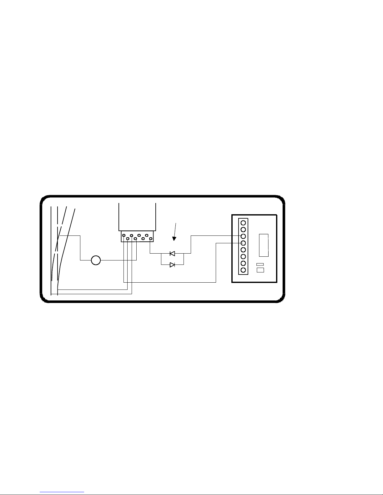
vSee the diagram below for turnout position indicator light wiring. LEDs are wired in
series with the switch machine to indicate which position the turnout is thrown. Most
LEDs will handle up to 25mA, the switch motor acts as the current limiting device for
the LEDs. We use red and green LEDs but any color will do. The switch machine will
run a bit slower with LEDs installed due to about a 1.5 volt loss in the LED.
TIP:
If you use power routing turnouts such as Peco Electro-Frog, Shinohara or Walthers
we suggest wiring a #1156 automotive taillight bulb in series with the points of the
turnout (see above). This will prevent short circuits from shutting down your power
booster in the event you enter the turnout from the frog end without aligning the points.
The warranty is voided if the decoder is miswired, connected to more than 22 volts, or
used with switch motors drawing more than 40mA.
Warranty
This decoder is fully factory tested and warranted against manufacturing defects for a period of 1 year. As the
circumstances under which this decoder is installed can not be controlled, failure of the decoder due to
installation problems can not be warranted. This includes misuse, miswiring, operation under loads beyond the
design range of the decoder or short circuits in the locomotive manufacturer’s factory wiring. If the decoder fails
for non-warranted reasons NCE will replace the decoder, no questions asked, for $10 US plus $2 shipping. For
warranty or non-warranty replacement send the decoder (an any payment, if required) to:
NCE Warranty Center 899 Ridge Road Webster, New York 14580
05240136
05240136
The terms Silent Running, Power Cab, Power Pro, Powerhouse Digital Command Control, ProCab and the NCE logo with
“Power of DCC” slogan are trademarks of NCE Corporation. Tortoise is a trademark of Circuitron, Inc.
Last revised: 8 November 2006 Page4
RED
GREEN
#1156
Bulb
LEDs
Tortoise
Machine
Shown
 Loading...