

Page 1
Power Cab
Power Cab
System Reference
System Reference
Manual
Manual
Rev. 1.65
1
Page 2
NCE
CAB
LOC:1234
FWD: 000
12:00AM
L1-3---
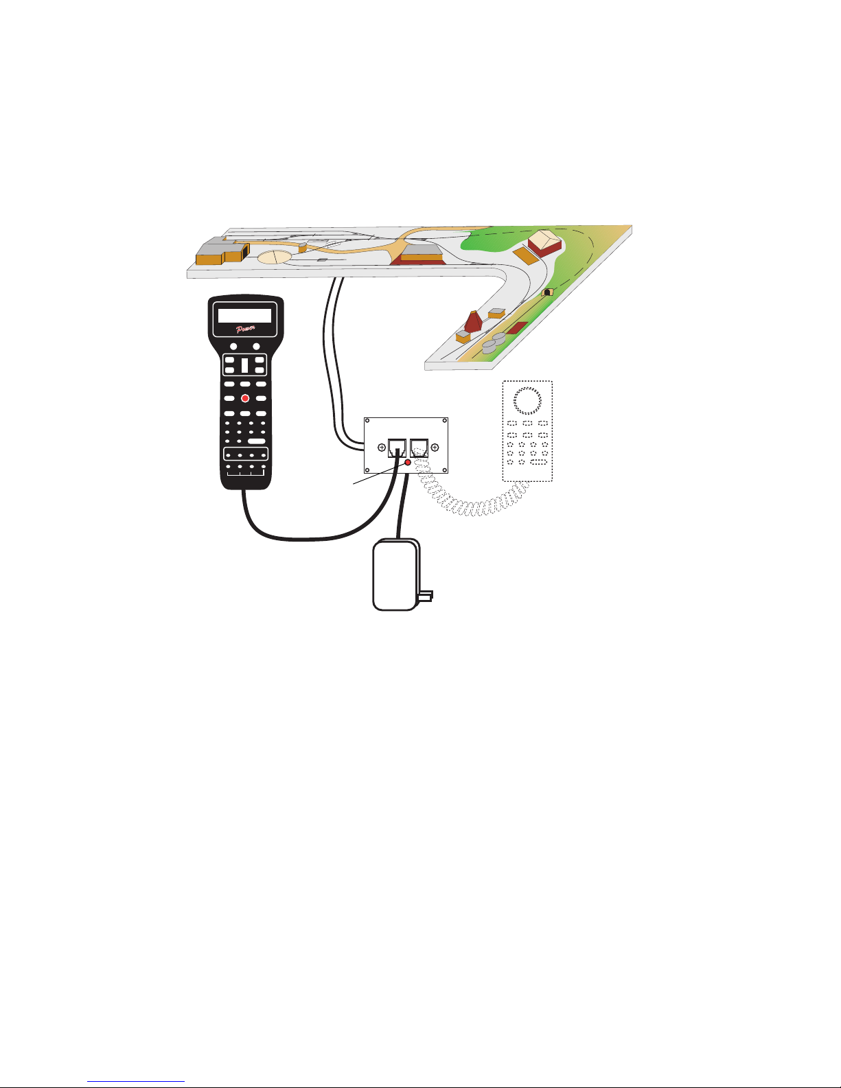
16ga. stranded wire
Power Panel
Red LED on
bottom of panel
6 Wire FLAT
Cable
Power Supply
P114
Basic Set Up of the
ower Cab System
P
Optional Extra
Cab
our Power CabTM is a full featured DCC system. It must be used with the 6 wire,
Y
FLAT cable supplied. All features described in this manual are available to you when
used in the Power Cab
ProTM NCE system, you can use the Power Cab
coiled cord that is also supplied. An NCE P114 power supply (13.8VDC Regulated) is
the supplied transformer for your system.
2
TM
mode. If you own or operate with a PowerHouseTM or Power
TM
as a Pro CabTM using the 4 wire
Page 3

Quick Start
Contents of the Power CabTM System:
Power Cab
Seven foot flat cable Coil Cord (4 wire) to use as a Pro Cab
Power Supply Power CabTM system reference manual
We recommend that you follow the instructions below to connect your system to a
mall test track first. After your system is checked out completely and known to be
s
working then consider the final installation locations for components and connections
to the track.
TRYING OUT YOUR POWER CABTM:
#1 Assemble the Power Panel by screwing the black plate to the circuit board with
#2 Connect the long 7 foot flat cable from the Power CabTM into the socket marked
socket).
#3 Use a small, flat screw driver to attach the test track feeder wires to the small
the connections.
#4 If you have a locomotive with a DCC decoder already installed place it on the
#5 Plug the power supply into the socket marked POWER. Plug the power supply
on and off your have a short. shut off power
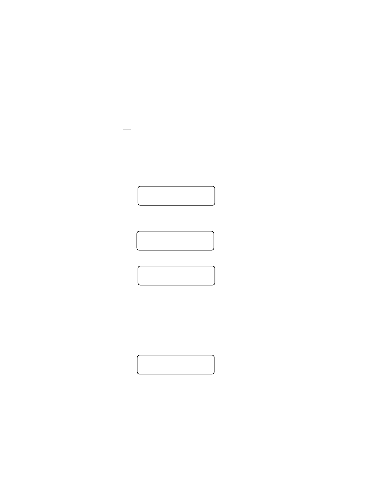
#6 The display of the cab should look something like:
This is what we call the ‘NORMAL DISPLAY’. The fast clock in the upper right hand
corner will most likely show a different time.
TM
screws provided.
(on the drawing) POWER CABTM (with the LED below the jacks) use the left
two place connector. Make sure that there are no shorts or frayed wires between
track.
into a wall outlet. If the red light of the panel lights up you are ready to go. If it blinks
Power Panel (marked PCAB-PP)
LOC: 003 00:03AMLOC: 003 00:03AM
LOC: 003 00:03AM
LOC: 003 00:03AMLOC: 003 00:03AM
FWD: 000 -------FWD: 000 -------
FWD: 000 -------
FWD: 000 -------FWD: 000 -------
The following cab buttons must be pressed in the proper sequence to acquire control
of the locomotive #3 (in the above example locomotive #3 is already selected):
Note: By convention, locomotive decoders usually have their short address set to 3
at the factory.
a. Press SELECT LOCO button once.
b. Press the “3” button once. DO NOT press 0 then 3.
c. Press ENTER.
TIP #1 If you make a mistake while entering numbers on the cab just keep pressing
more numbers until the number entry field clears, then enter the correct numbers.
TIP #2 Whenever the cab is waiting for you to enter data (a flashing black square is
on the screen at the point where the numbers will go) you can press the PROG/ESC
key to “escape” what you were doing and return to normal operation mode.
TIP #3 Whenever you have pressed a button (such as SELECT LOCO) and you
want to keep what ever number that is already on the screen just press ENTER.
#7 To operate the locomotive, the following controls are used:
a. The thumbwheel will increase/decrease speed. The speed control buttons
that flank the thumbwheel on either side may also be used as desired to
control the loco speed.
b. Pressing the DIRECTION button will cause the loco direction to reverse.
CONGRATULATIONS! You are now operating a locomotive with DCC control. In
most cases, less than ten minutes has elapsed since you started reading this Quick
Start Guide.
3
Page 4
COMP
Operating one locomotive is fun — for awhile. But operating two locomotives is a lot
more fun for a much longer time. Advancing beyond this simple DCC testing requires
decoder installation into more locomotives and perhaps a few straight pieces added
to your circle of track. After you have two locomotives with decoders we can
continue with both locomotives simultaneously operating under DCC control. At least
one locomotive will need to be programmed with a different address.
LETING THE QUICK START
PROGRAMMING A LOCOMOTIVE
ADDRESS
#1 The first item of business in this section is to remove any locomotives from the
layout that will not be programmed.
#2 Place the locomotive to be programmed with an installed decoder on the track.
#3 Press the PROG/ESC button four times (bottom left corner) to get to the
programming track menu.
Your cab should read:
SELMODE xx:xxPMSELMODE xx:xxPM
SELMODE xx:xxPM
SELMODE xx:xxPMSELMODE xx:xxPM
USE PROGRAM TRKUSE PROGRAM TRK
USE PROGRAM TRK
USE PROGRAM TRKUSE PROGRAM TRK
xx:xx represents the fast clock which may display any time at this point.
#4 Press ENTER to use the programming track and you will see:
PROG TRK xx:xxPMPROG TRK xx:xxPM
PROG TRK xx:xxPM
PROG TRK xx:xxPMPROG TRK xx:xxPM
1=STD 2=CV 3=REG1=STD 2=CV 3=REG
1=STD 2=CV 3=REG
1=STD 2=CV 3=REG1=STD 2=CV 3=REG
#5 Press “1” to use Standard programming. You will see:
MAIN OFF xx:xxPM
MAIN OFF xx:xxPM
MAIN OFF xx:xxPM
MAIN OFF xx:xxPM
MAIN OFF xx:xxPM
MANUFACTURER:___
MANUFACTURER:___
MANUFACTURER:___
MANUFACTURER:___
MANUFACTURER:___
After a moment the blank space after MANUFACTURER: will be filled in with the
NMRA code for the maker of the decoder. All manufacturers have different codes.
If you get a CAN NOT READ CV message the decoder is not responding. Check the
locomotive, decoder and programming track wiring. An older decoder that uses
“paged” mode (discussed later) can take up to 15 seconds to read the values.
#6 Press ENTER to read the decoder version installed in your locomotive.
#7 Press ENTER again to see:
ACTIVE ADR:SHORT
SETUP ADR 1=YES
SETUP ADR 1=YES
SETUP ADR 1=YES
SETUP ADR 1=YES
SETUP ADR 1=YES
ACTIVE ADR:SHORT
ACTIVE ADR:SHORT
ACTIVE ADR:SHORT
ACTIVE ADR:SHORT
4
Page 5

y convention all DCC locomotive decoders are set to short address 3 or long
B
address 3333 at the factory. If your decoder has not had its address changed
you will see a short address as the active address. Press 1 to set up the
address.
ACTIVE ADR:SHORTACTIVE ADR:SHORT
ACTIVE ADR:SHORT
ACTIVE ADR:SHORTACTIVE ADR:SHORT
SHORT ADR: 003SHORT ADR: 003
SHORT ADR: 003
SHORT ADR: 003SHORT ADR: 003
TIP A decoder can have 2 different addresses, the Short Address (values from 1-
127) or the Long Address (sometimes called 4 digit with a range of 0000-9999). A
decoder can use one or the other but not both at the same time. Some entry level
decoders can only use the Short Address.
#8 Press ENTER to keep the current short address set to 3.
#9 Press ENTER to skip activating the short address.
#10 Next you will see the Long Address (which is probably set to 0000 or sometimes
to 9999). With older decoders, it may take a up to 30 seconds to read the long
address.
This is the address we will change.
#11 You will likely want to enter the number on the side of the locomotive cab as the
Long Address. Type in the number of the locomotive and press ENTER.
#12 Press 1 to activate the Long Address.
You have just changed the Long Address.
At this point, press PROG/ESC twice to exit the program track mode.
You have just completed the hardest part of DCC… programming the locomotive on
the programming track.
To select the locomotive:
a. Press SELECT LOCO button
b. Press the digits corresponding to the Long Address you just programmed..
c. Press ENTER
At this point you should have control of the locomotive. Now is the time to program up
a second locomotive and run them both.
RUNNING TWO LOCOMOTIVES WITH ONE CAB
#1 Select the first locomotive you wish to run (SELECT LOCO followed by its
address then ENTER).
#2 Press RECALL to store this locomotive in one of the internal recall “slots” of the
cab. The display of the cab will now show a locomotive of 000.
#3 Select the second locomotive and start running it.
#4 By pressing RECALL you can toggle back and forth between the two different
locomotives. At any time you can select a new locomotive “over the top” of any
locomotive already on the display. The existing locomotive will be forgotten by the
cab with the new one taking it’s place. The one in RECALL will remain available for
recall.
5
Page 6

CUSTOMER SERVICE
Customer Servic
dealer. It is faster to deal direct with the factory. Please write or call us before
returning any products to our warranty center. Sometimes the problem is
easily solved over the phone. If writing make sure you include your name,
address and phone number and the times that you can be reached at that
number. This will greatly expedite our service to you if you have questions.
NCE Warranty Center
82 East Main St.
Webster, NY 14580
Phone: (585) 265-0230
Fax: (585) 265-0234
Email Address: support@ncecorporation.com
Web Site: www.ncedcc.com
We reserve the right to either repair or replace components sent to us for inwarranty service. The warranty period will begin on the date shown on your
retail sales receipt. Please do not send anything for repair without first
writing or calling to explain the problem. Also remember to include your
name, address and phone number with a brief description of the problem.
e is handled through our factory warranty center or by your
REGISTER MY SYSTEM… WHY?
By registering your Power CabTM or Smart Booster DCC system with us you
will receive personal notification of any software and hardware updates. At
various times we provide free updates to our customers. At other times there
is a nominal charge to cover shipping and handling (usually about $5 to
$10). We do NOT use your name or address for any purpose other than
upgrade notification. We will not sell or otherwise provide your personal
information to any other person, company or entity.
ABOUT THIS MANUAL
This manual covers the installation and operation of the NCE Power Cab
DCC system. It is not a comprehensive tutorial on all the aspects of Digital
Command Control. It is not necessary to know the inner workings of DCC to
use this system. Some users may wish to delve deeper into the how and why
of Digital Command Control for model railroads, especially those wishing to
use the computer interface of the Power CabTM. For those interested in the
“nuts and bolts” we recommend the reading of the following NMRA
Standards and Recommended Practices as they pertain to DCC. Applicable
standards are: S-9, S9.1 and S-9.2 and Recommend Practices: RP-9.1.1
through RP-9.2.4. These documents are available via the Internet at
www.nmra.org.
Editorial help has been provided by Lou Nost of Penfield, New York.The
NCE Publications Department wrote this manual. Please address comments
regarding the manual to:
NCE Publications Dept.
82 East Main St.
Webster, NY 14580
[email protected]
6
TM
Page 7

™
Power Cab
The Finest in Digital Command Control ~
~
System
Reference Manual
for Power Cab
V 1.65
Copyright 2015
™
NCE Corporation
82 East Main St.
Webster, NY 14580
(585) 265-0230
7
Page 8

TABLE OF CONTENTS
QUICK START ............................................................................................................ 1
COMPLETING THE QUICK START ......................................................................... 2
PROGRAMMING A LOCOMOTIVE ADDRESS ....................................................... 2
RUNNING TWO LOCOMOTIVES WITH ONE CAB ................................................ 3
CUSTOMER SERVICE ............................................................................................... 4
REGISTER MY SYSTEM… WHY? ............................................................................ 4
TABLE OF CONTENTS ............................................................................................. 6
INSTALLING DECODERS ......................................................................................... 8
PRECAUTIONARY NOTES FOR DECODERS ........................................................ 9
GENERAL SYSTEM INSTALLATION ...................................................................... 10
DEVICE LOCATIONS ........................................................................................... 10
PROGRAMMING TRACK .................................................................................... 10
NCE AUTO SWITCH ............................................................................................ 11
REVERSE BLOCKS, WYES, AND CROSSOVERS ........................................... 11
WIRING .................................................................................................................. 11
SYSTEM POWER PANEL DESCRIPTION ............................................................. 12
THE POWER CABTM SYSTEM UNIT ....................................................................... 13
SET THE PRO CABTM ADDRESS............................................................................ 14
THE LCD SCREEN ............................................................................................... 14
LOCOMOTIVE CONTROL AREA ....................................................................... 14
SPEED CONTROL SECTION ............................................................................. 15
COMMONLY USED BUTTONS ........................................................................... 15
LOCO AND ACCESSORY SELECTION GROUP ............................................. 16
DATA ENTRY/FUNCTION CONTROL ............................................................... 16
CONSIST SETUP GROUP .................................................................................. 16
PROGRAMMING AND EXTENDED FUNCTION CONTROL ........................... 17
CAB SETUP ........................................................................................................... 18
CAB BUTTON NUMBERING SCHEME .............................................................. 20
TABLE OF FACTORY DEFAULT VALUES ........................................................ 21
6 WIRE CAB BUS CABLE WITH RJ-12 CONNECTORS .................................. 21
4 WIRE CAB BUS CABLE WITH RJ-12 CONNECTORS .................................. 22
POWER CABTM SPECIFICATIONS ......................................................................... 22
OPERATING PROCEDURES .................................................................................. 23
THE “NORMAL” DISPLAY .................................................................................... 23
SELECTING A LOCOMOTIVE OR CONSIST ................................................... 23
CONTROLLING HEADLIGHTS AND OTHER DECODER FUNCTIONS ........ 24
OLD AND ADVANCED CONSISTS EXPLAINED ................................................... 25
ADVANCED CONSISTS ....................................................................................... 25
OLD STYLE CONSISTS (ALSO CALLED BRUTE FORCE OR UNIVERSAL) 25
SETTING UP AN ADVANCED CONSIST ............................................................... 25
DROPPING A LOCOMOTIVE FROM AN ADVANCED CONSIST ................... 27
ADDING A LOCO TO AN ADVANCED CONSIST ............................................. 27
CLEARING AN ADVANCED CONSIST .............................................................. 28
CHANGING THE LEAD/REAR LOCO ................................................................ 28
OLD STYLE CONSISTS ........................................................................................... 29
SETUP AN OLD STYLE CONSIST ..................................................................... 29
ADDING A REAR LOCO TO AN OLD STYLE CONSIST ................................. 29
CLEARING AN OLD STYLE CONSIST .............................................................. 30
CONTROLLING TURNOUTS AND OTHER ACCESSORIES .............................. 31
MOMENTUM BUTTON ............................................................................................ 32
USING MACROS TO CONTROL TURNOUTS ..................................................... 33
MACROS EXPLAINED ......................................................................................... 33
PROGRAMMING PROCEDURES .......................................................................... 34
ACCESSING PROGRAMMING MODES ............................................................ 34
PROGRAMMING MENUS TABLE OF CONTENTS ............................................. 35
PROGRAMMING ON THE MAIN ........................................................................ 37
8
Page 9

ASSIGNING A LOCO TO A CAB ........................................................................ 44
SET THE SYSTEM CLOCK .................................................................................. 44
USE PROGRAM TRACK ...................................................................................... 46
SETUP COMMAND STATION ............................................................................. 55
SETTING THE CAB PARAMETERS ................................................................... 57
PROGRAM ACCESSORY DECODERS ON THE MAIN ................................... 59
PROGRAM MACROS ........................................................................................... 59
BROWSE CONSISTS ........................................................................................... 61
PROGRAM SIGNAL DECODERS ....................................................................... 61
HELPFUL HINTS ....................................................................................................... 62
TROUBLE SHOOTING ............................................................................................ 63
COPYRIGHTS ........................................................................................................... 64
WARRANTY ............................................................................................................... 64
FCC STATEMENT .................................................................................................... 65
ABOUT NCE .............................................................................................................. 65
MENU NAVIGATION CHARTS ............................................................ BACK COVER
9
Page 10
INSTALLING HARD WIRED DECODERS
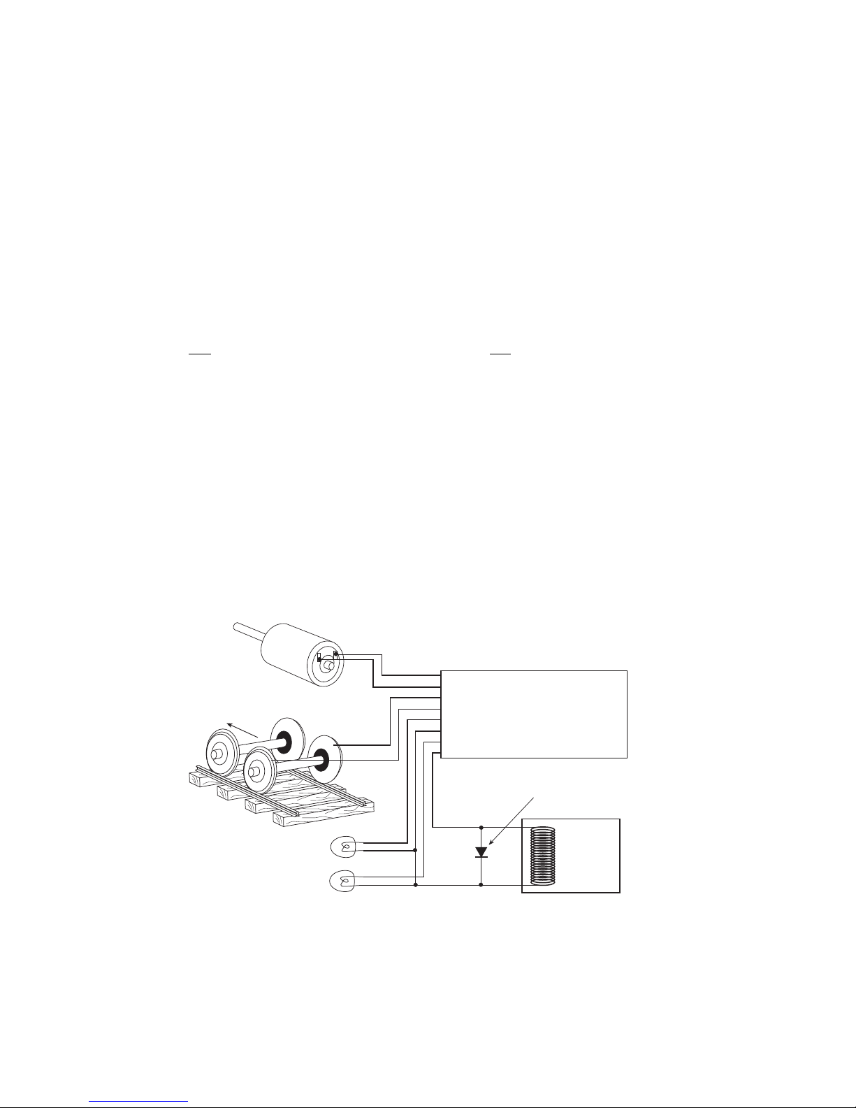
Note 1: The function common (blue wire) is the positive lead providing rectified DC voltage. If you
elect to NOT use the common, power the light or other device from either track power pickup for
half-wave operation (approx. 1/2 voltage).
Relay, Smoke
unit, etc.
-
+
Note: If a function controlled device presents
inductive load (such as a relay), always use
a suppression diode (such as 1N4004 or 1N914)
across the device.
Motor -
Motor +
Right Track Power Pickup
Left Track Power Pickup
Forward Light
Light or Function Common (see note 1)
Reverse Light
Function 1 (not on all decoders)
Gray
Orange
Red
Black
White
Blue
Yellow
Green
Blue
Left Rail
Firemans Side
Right Rail
Engineers Side
Motor
WARNING: To prevent decoder damage,
ALWAYS make sure the motor brushes are
properly isolated before applying power.
Forward
Locomotive decoders come as convenient plug-in models (usually designed for one
specific loco or family of locomotives) or as lower cost “hard wired” types that can be
wired directly to many different locomotives. Below is a description of a typical hard
wired installation.
Read the following section on decoders before starting. There are shortcuts to
temporary installations of the other components, but do not shortcut the decoder. We
recommend you get your first decoder installed by a dealer or locomotive
manufacturer just so you have a good example of how it’s done.
The most important part of a successful decoder installation is proper isolation of
both motor brushes from the track so that they are driven only by the decoder.
Failure to isolate will definitely damage the decoder. Damage caused by failure to
isolate the motor is not covered by the guarantee or warranty.
We find it preferable to mount the decoder with 1/2" wide 3M photo-mount double
sided foam tape (we get ours at the local supermarket).
Before test running your newly converted locomotive on full power double check
your wiring to make sure the motor is fully isolated and that there are no pinched or
broken wires. We see many decoders returned due to wires getting pinched between
the body shell and frame causing shorts.
Due to the high in-rush current of incandescent grain-of-wheat type bulbs (about 10
times the normal operating current) we have rated the decoder function outputs at
100mA each. We recommend Miniatronics part number 18-014-10 (2.4mm diameter
14 volt/30mA) bulbs for good results. If you are running higher voltages you will need
to use 16 or 18 volt bulbs.
10
Page 11

If you need to use higher current lamps (50-150mA) we recommend a 22 ohm 1/4
Watt resistor in series with each bulb (this will also greatly extend bulb life). The
function outputs are rated at 150mA continuous if used with LEDs or other low inrush devices.
Always make sure the motor is isolated from the frame. Always make sure
metal couplers are isolated from the frame.
PRECAUTIONARY NOTES FOR DECODERS
l MAKE SURE NO METAL PART OF THE LOCOMOTIVE TOUCHES ANY METAL
PART OF THE DECODER. APPLY ELECTRICAL TAPE TO THE INTERIOR OF
THE LOCO AT ANY QUESTIONABLE POINTS.
l THERE MUST BE NO ELECTRICAL CONNECTION BETWEEN THE MOTOR
AND THE RAILS. BOTH MOTOR TERMINALS MUST BE ELECTRICALLY
ISOLATED FROM THE MOTOR FRAME AND BODY.
l IF YOU USE METAL COUPLERS MAKE SURE THE COUPLERS ARE
INSULATED FROM THE FRAME. THIS CAN CAUSE MYSTERIOUS PROBLEMS
WHEN RUNNING TWO OR MORE LOCOMOTIVES COUPLED TOGETHER.
l DO NOT USE CONVENTIONAL (older) DECODERS WITH CORELESS
MOTORS.
NCE decoders that are designated SR (Silent Running) are high frequency motor
drive decoders. These will not harm coreless motors.
l Test the locomotive to assure good analog (DC) operation. Poor running
locomotives will not run well with DCC either. Test the loco under a “stalled”
condition. First connect ammeter between the DC power supply and the track.
Remove the loco’s shell. Increase power to the loco until it reaches at least 12
Volts. Now stall the motor by squeezing the flywheel until it stops. With locomotives
without flywheels, push down on the mechanism until the wheels stop turning. Note
the reading on the meter. The decoder rating needs to exceed the highest
amperage reading otherwise the decoder will cause the loco to have intermittent
stops when operating at the decoders’ rated amperage.
l We suggest installing the wiring harnesses with plugs for all leads being used in
order to facilitate decoder removal in the future.
l Lights and motor stall current should not exceed the values listed for each
decoder. Nor should their total exceed the amount of current remaining after
testing the loco motor “stalled”. The Function common (blue wire), is track voltage.
l Make a wiring diagram of your locomotive’s motor power and lighting. Copy it and
show how you are going to insulate the motor from the frame, if it is not already
insulated, and where you are going to cut the wires from the track pickups to the
motor and lights. LGB locomotives can be tricky here.
l The power for the Functions normally is connected to the Blue wire. This will
supply the lights with 14-15 volts (for the NORMAL setting). If you connect one
wire of a light bulb to one of the rails (Red or Black) and the other wire to the
function wire, the voltage to the lights will be cut to half the normal voltage (7 - 8
volts).
l Place the loco on the programming track and refer to the section
“PROGRAMMING ON THE PROGRAMMING TRACK”. Almost all decoders come
from the factory with the short address “3”.
When wiring, the right hand rail is the rail to the right of the observer standing
between the rails with their back to the front of the locomotive, also referred to as the
“engineers side”. For traction systems, the overhead wire is considered the right
hand rail.
11
Page 12
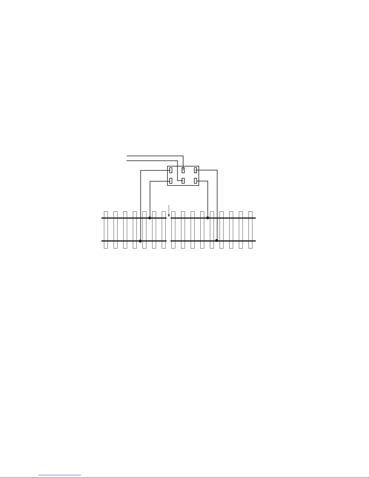
GENERAL SYSTEM INSTALLATION
Insulated
joiners in
BOTH rails
Power Cab
track connector
MAIN TRACK
PROGRAMMING TRACK
DEVICE LOCATIONS
The physical locations for the Power CabTM can be anywhere. We suggest a location
where the LED on the front of the Power Panel can be easily seen should there be a
problem. Cab Bus panels such as the UTP or UTP-DIN are set up to use prewired
four or six wire RJ12 telephone type cables to connect from panel to panel behind
the layout fascia. Page 21 has a diagram of the proper wiring for these cables. We
recommend placing the panels about 7-8 feet apart. In yard areas closer spacing
may be needed. We suggest that a plug be no more than three feet from any siding
where an operator would most likely stop and spend some time. Consider that
operators will tend to gather at these panels so placement in crowded aisles may
require care.
A SEPARATE PROGRAMMING TRACK
The programming track is a separate section of track where programming (setting
the locomotive address and/or other internal parameters) takes place. The
programming track must be electrically separate from the main trackage. The end of
a convenient spur track will work fine. Install insulated joiners in both rails, directly
across the track from each other. Allow enough length for your longest locomotive.
If desired, the programming track can be connected with a double-pole double-throw
switch that is used to isolate this segment from the rest of your layout. This track is
needed to complete the necessary start up programming for most decoder-equipped
locos.
When the switch is set to use the programming track, the remainder of the layout is
stopped. With NCE decoders, all parameters can be changed on the mainline using
the “Programming on the Main” feature, without shutting down the whole layout.
Some other manufacturer’s decoders do not support “Programming on the Main” so
a programming track is required. Some owners have setup their shop loop to be DC,
DCC, and programming track, then they can do all the testing in their shop and have
only ready-to-run loco’s on the layout.
12
Page 13
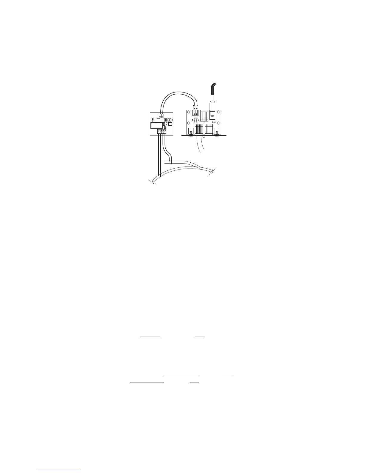
MAIN PROG
DCC
NCE
AUTO-SW
POWER
PCAB-PP
TRACK
Double Gaps
Program Track
Main Track
Power Cab
Power Supply
Track Out
DCC
Program
Main
Power Cab
Power Panel
Auto SW
You can use the optional NCE Auto SW to automatically turn off your mainline track
and let you program one locomotive at a time on your program track. Part number
524-226 is the Auto SW. When the Auto-SW is set to mainline, the program track will
be off.
Installation of the Auto-SW to the Power CabTM System
REVERSE BLOCKS, WYES, AND CROSSOVERS
Reversing loops/sections still present the same potential for short circuits as
conventional DC layouts. You can use commercial auto-reverse loop modules such
as the MRC AD520 or Tony’s Trains Auto Reverser.
WIRING
If you already have a layout, your existing wiring most likely can be used without
problems as long as it can handle a continuous 2 amp current. We suggest a “bus”
of two large gauge (18 AWG) wires that follow the general track route of your layout
with feeder wires to the track about every 3-6 feet. For the most trouble free
operation we suggest a feeder to EVERY piece of rail. Don’t rely on the rail joiners to
handle 2 Amps of current. To prevent voltage drop over long runs a chart of
recommended track bus wire sizes is found below.
For the hobbyist wiring up a new layout our suggested wire sizes based on voltage
drop are:
Runs to twenty-five feet ...... #18
Runs to fifty feet................... #16
For best results on long runs (over 20 feet), twist the bus wires about three turns per
foot.
If you are planning a layout expansion that will require more power (more trains) in
the future, we suggest using #16 for runs to 25 feet and #14 for longer runs.
There is no special requirement for routing the power conductors with DCC. If you
are going to have long runs of cab bus cabling along the front of the layout you
should run the track bus wires nearer the rear to prevent potential “crosstalk”
between the track signal and the cab bus.
13
Page 14
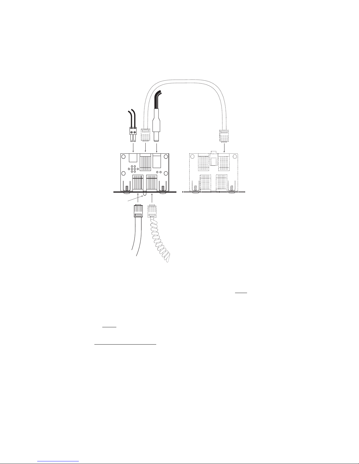
SYSTEM POWER PANEL DESCRIPTION
POWER
PCAB-PP
TRACK
Power
Track Wires
Red LED glows
when there is
power to track
Optional UTP Panel(s)
provide extra plug-in
locations for optional cab,
Mini Panel and/or USB
Interface
Optional
Power Cab
here ONLY
Extra Cab
(must be
set to cab
address 3)
NOTES:
l The Power CabTM will deliver track power only if it is plugged in to the LEFT socket.
With the flat, 6-wire cable.
l Use only the provided P114 power supply or a voltage regulated 10-15 VDC
supply of 3 Amps or less.
l The flat 6 wire cable carries track power from the Power CabTM to the Power
PanelTM. Use this cable for Power CabTM operations.
l The 4 wire coilcord DOES NOT carry track power. Use this cable when you use
the Power CabTM as a Pro CabTM on another system.
14
Page 15
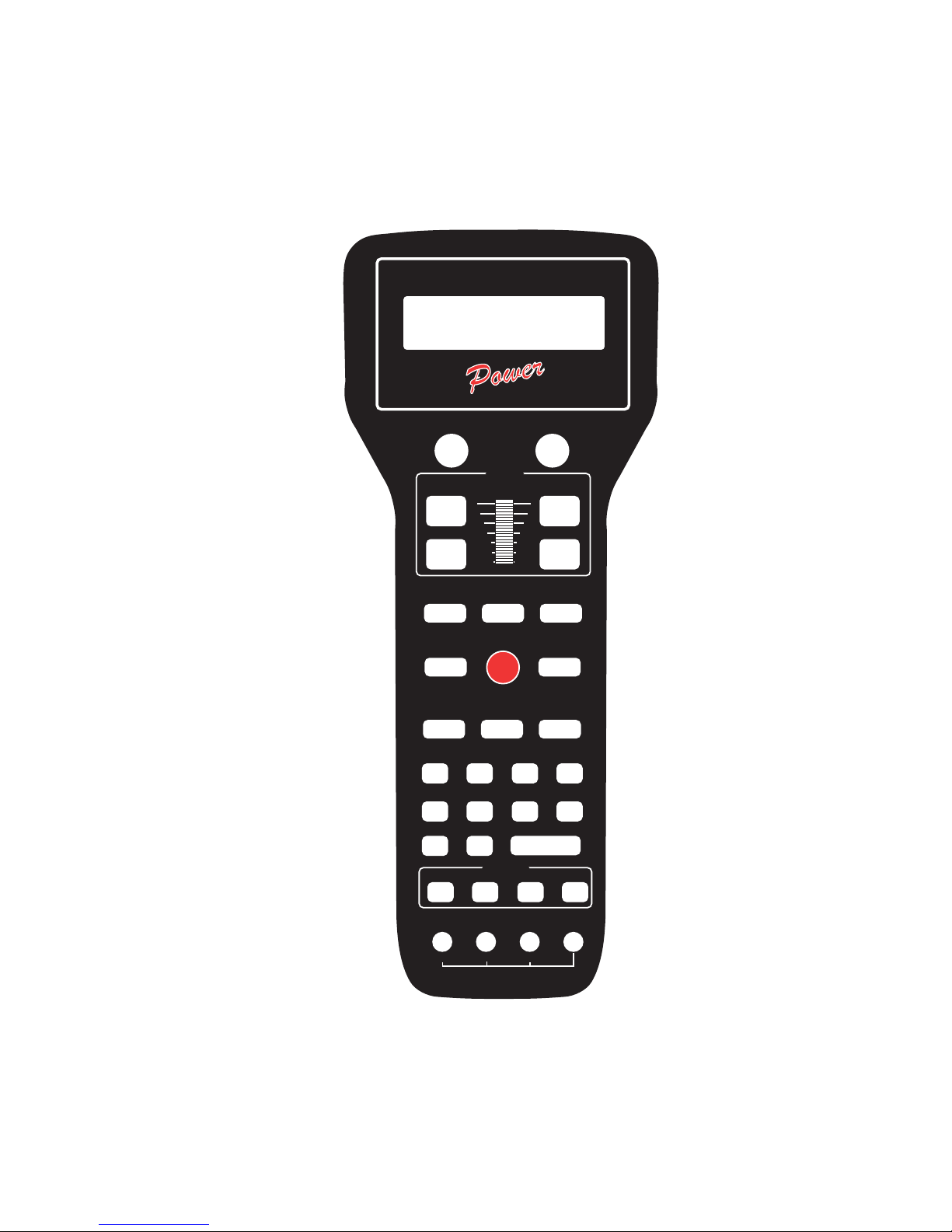
DCC COMPATIBLE COMMAND CONTROL
DIRECTION MOMENTUM
INC FAST
DEC FAST
INC
DEC
HORN/
WHISTLE BELL HEADLIGHT
OPTION RECALL
EMERGENCY
STOP
SELECT
LOCO MACRO
SELECT
ACCY
1 2 3 4
5 6 7 8
9 0 ENTER
PROG/ESC EXPN 28/128 SHIFT
CONSIST
SET UP
SPEED
LOC:1234
FWD: 000
12:00AM
L1-3---
CLEAR ADD
DEL
F10 F12F11
NCE
CAB
THE POWER CAB
TM
15
Page 16
SET THE PROCAB ADDRESS -
DIRECTION MOMENTUM
DCC COMPATIBLE COMMAND CONTROL
LOC:1234
FWD: 000
12:00AM
L1-3---
NCE
CAB
If the Power Cab is to be used as a Pro Cab
Just as every locomotive has a separate number (address in DCC terms) each cab
needs a separate address so the command station can distinguish one cab from
another. Each Power CabTM is shipped from the factory with the address of 2. When
the Power CabTM is used in Power CabTM mode, the address is always 2 regardless of
the Pro CabTM address setting. To easily change the address:
1. Power up your Power CabTM system.
2. Plug in the Power CabTM cable to the CAB BUS connector of the Power Cab
3. Unplug your Power CabTM at the base of the cab
4. Press and hold the SELECT LOCO button while re-plugging in the cable you just
removed from the cab
5. You should see the following display on the cab:
NCE PROCAB V1.3NCE PROCAB V1.3
NCE PROCAB V1.3
NCE PROCAB V1.3NCE PROCAB V1.3
CAB ADDRESS = 02CAB ADDRESS = 02
CAB ADDRESS = 02
CAB ADDRESS = 02CAB ADDRESS = 02
6. The cursor will be flashing over the 0 of “02”. Type in the new cab number. In this
case, you will press “3” (valid range = 1-63) followed by ENTER.
7. Press PROG/ESC to skip setting all the other cab setup options. They will be
discussed later on page 20 of this manual.
TM
TM
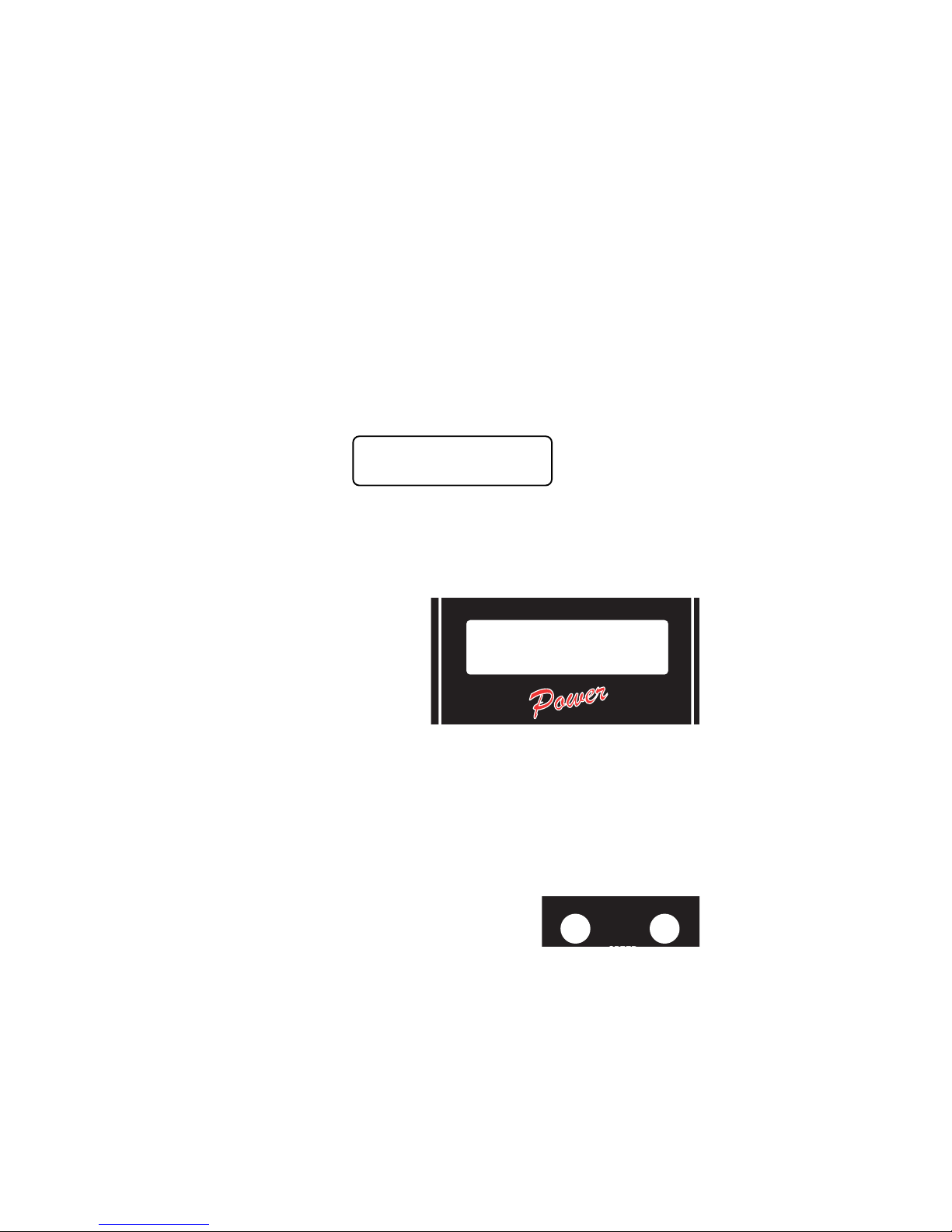
THE LCD SCREEN
The LCD screen provides you with
messages from the Power Cab
Command Station. This information
includes: locomotive status, scale
time, command prompts and
messages regarding programming
decoders. The drawing above
shows how the display looks
during normal operation. The top
line of the display includes the locomotive number being controlled and the scale
time. The second line shows the direction, speed and status of the locomotive
function outputs. Decoder functions are represented with “L” for headlight or the
function number 1 through 6 being ON. A dash (“-”) indicating the function is OFF
TM
LOCOMOTIVE CONTROL AREA
DIRECTION
The DIR key changes the direction of your loco or
consist. The current direction is displayed as the first
three characters of the second line on the screen.
This button is disabled if the cab is in Yard mode.
Holding down the DIRECTION button while turning the system on will cause it to
immediately go to Power CabTM mode.
MOMENTUM
This key changes the acceleration/deceleration rate of the currently controlled
locomotive/consist.
16
Page 17
SPEED CONTROL SECTION
INC FAST
DEC FAST
INC
DEC
SPEED
HORN/
WHISTLE BELL HEADLIGHT
OPTION RECALL
EMERGENCY
STOP
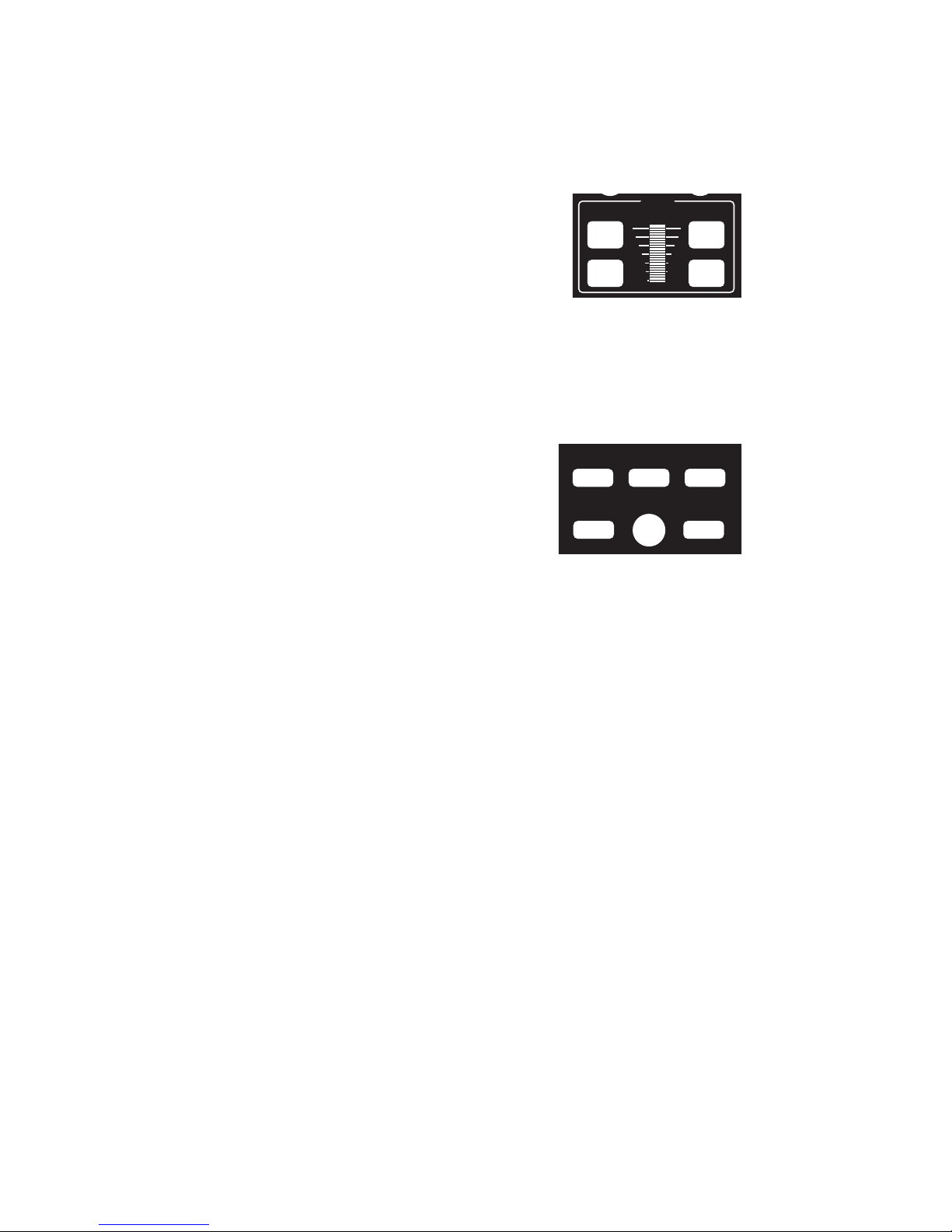
The digital encoder equipped Power CabTM allows
you to use both the speed buttons and the knob for
controlling the speed of your locomotive. The left
two keys increase or decrease the speed by either
4 or 10 speed steps, depending on the speed step
mode (28 or 128), whereas the right keys increase
and decrease the speed by one speed step at a
time.
The knob increases the speed by rotating it up and
decreases the speed when it is rotated down.
Power CabsTM have a feature called ballistic tracking. The faster you rotate the knob
the faster it will increase or decrease the speed. This rate is adjustable from 0-7. The
factory default value is 3. See the Cab Setup section later in this manual.
Note: Speed buttons are disabled if the Power CabTM is in Yard mode.
COMMONLY USED BUTTONS
HORN/WHISTLE
Factory default is to operate function 2 when this
button is pushed. Unlike other keys which toggle
functions on/off this key blows the horn as long
as the key is held down. Pressing the 2 key will
still toggle the function on or off.
BELL
Factory default is a toggle for function “1” on or off with each button press. This can
be changed in the Set Cab Params menu.
HEADLIGHT
Toggles the Headlight on and off. With DCC, the headlight is defined as Function 0,
and pressing the 0 (zero) key will perform the same function, but we felt the headlight
warranted its own button and a more convenient location.
OPTION
This button can be programmed to act as any button you wish (see the CAB SETUP
section on page 18, step 8).
EMERGENCY STOP
Pressing EMERGENCY STOP will stop the active loco/consist for this Cab only.
Speed will be immediately set to zero (no momentum). Loco is restarted by changing
the speed step or direction.
RECALL
This button toggles between the last two to six locomotives or consists addressed.
RECALL allows you to keep two to six locomotives and/or consists active in the
command station memory and access them in “round-robin” fashion with each press
of the button. Think of RECALL as being a set of memory slots. To put a locomotive
in a recall “slot”, press SELECT LOCO and enter the loco or consist to be operated
followed by pressing ENTER. To put another locomotive in the next slot, first press
RECALL to access the next slot. Now press SELECT LOCO and enter the second
loco followed by pressing ENTER. When additional trains are to be added either a
“slot” with “000” or an expendable loco/consist must be displayed on the screen.
Whatever is on the display will be replaced with the new loco/consist.
17
Page 18
The number of RECALLS for each cab can be changed within the “SET CAB
SELECT
LOCO MACRO
SELECT
ACCY
1 2 3 4
5 6 7 8
9 0 ENTER
CONSIST
SET UP
CLEAR ADD
DEL
PARAMS” menu (see PROG button description). The factory default value is two.
You may also “clear out” any locomotives in the recall slots using the “SET CAB
PARAMS” menu. We don’t advise using RECALL in Yard mode. Because the
‘DIRECTION’ can be fouled inside the ProCab.
LOCO and ACCESSORY SELECTION GROUP
SELECT LOCO
This allows the selection of a locomotive/consist to
operate. Press this key, the loco/consist number,
then ENTER.
When loco is selected, Speed Step 0 and Functions
0 through 8 commands are sent to the loco. This
serves to “Wake Up” sound decoders.
MACRO
When this key is pressed you are prompted to enter the macro number, then press
ENTER. Macros are used to control one or more accessories with a single
command.
This is especially useful for selecting a route through a switch ladder in a staging
yard or complex trackwork where it would be inefficient to throw several switches by
selecting them individually. Macros are explained in detail later on page 33.
SELECT ACCESSORY
For controlling “accessory” decoders that operate accessories such as switch
machines, lights, signals, etc.
DATA ENTRY/FUNCTION CONTROL
NUMBER KEYS
The keys 0 through 9 serve two purposes. First,
when operating a loco/consist if a number key is
pressed it toggles the corresponding function on the
loco (if that function is connected and supported by
the decoder). The second purpose is for typing in
numbers such as when selecting locomotives or
responding to screen prompts during programming.
ENTER
Used to confirm numeric inputs or select a programming mode.
CONSIST SETUP GROUP
Supports not only advanced decoders that respond
to the Extended Packet Format but also the older
entry-level decoders. For complete operating
instructions on consist makeup read the section on
SETTING UP A CONSIST on page 25.
SETUP
Starts the procedure for either creating an advanced or old style (some call it
Universal) consist.
18
Page 19
CLEAR
PROG/ESC EXPN 28/128 SHIFT
F10 F12F11
Disbands (breaks up) a consist.
ADD [LOCO]
Adds a locomotive to a consist.
DELETE [LOCO]
Drops a locomotive from a consist. For use with Advanced Consists ONLY (this
button is inactive with old style consists.
PROGRAMMING and EXTENDED FUNCTION
CONTROL
PROG/ESC/F10
Provides selection of the various system
menus available for setting up decoders,
cabs, time, etc.
This button also doubles as an “escape”
key during number/data entry. Whenever
the cursor (flashing rectangular box) is shown on the cab display to indicate the cab
is waiting for data to be input you can press PROG/ESC to cancel the data entry and
return to normal operations.
The following menus are accessed round robin fashion with each successive press
of the PROG/ESC key when in normal operations:
l First press: Program on the Main (Operations Mode programming)
l Second Press: Assign loco to Cab
l Third Press: Set Fast Clock
l Fourth Press: Use programming Track
l Fifth Press: Set up Command Station
l Sixth Press: Set up Cab Parameters
l Seventh Press: Program accessory decoders on the mainline
l Eighth Press: Set up Macros (switch route control)
l Ninth press: Browse Advanced Consists
l Tenth press: Program Signal decoders on the mainline
Pressing ENTER at any of the above menus will select that menu, pressing PROG/
ESC will step to the next menu. You can use ‘shortcuts’ to get to the menus you like.
For example: Pressing PROG/ESC followed by 4 takes you to the Program Track
menu.
Pressing SHIFT and PROG/ESC activates F10.
EXPN/F11
In Power CabTM mode, this button is reserved for future features. When the Power
Cab is used as a wireless Pro Cab, this button is used to access the radio setup
menu. When the cab is tethered, it toggles between the display of lines 1 and 2 of the
LCD display and lines 3 and 4. Pressing SHIFT and EXPN activates F11.
Pressing the EXPN key will show the status of functions 1 through 28. The top line of
the screen shows functions 1-14, ‘-’ means the function is off. A digit in the space
means the function is on. The second line of the screen shows functions 15 through
19
Page 20

28 in the same manner. Pressing the EXPN key a second time returns the cab to the
normal display.
28/128/F12
Provides the ability to toggle between 28 and 128 speed step operation of the active
loco/consist. Pressing this button will display the speed step mode you have selected
on the cab LCD. The LCD display will be set to the normal operation display the next
time a function is toggled or ENTER is pressed. Pressing SHIFT and 28/128
activates F12. When the Power CabTM is turned off, the default is set to 28 speed steps.
SHIFT
This button gives each key on the ProCab an “alter ego”. When pressed and held
while pressing another key on the cab the alternate value of that key can be used.
For example: To access the function F10 you simply press SHIFT and PROG/ESC
at the same time to activate FUNCTION 10. Every key can be programmed to any
current or future feature we may think up. This is like having a whole cab full of
OPTION keys. Each key is preprogrammed at the factory to one of these alternate
uses. Try pressing SHIFT and 4. This takes you directly to the USE THE
PROGRAMMING TRACK menu. A list of the shifted keys is tabulated on page 21.
EXTENDED FUNCTION CONTROL (F10 - F28)
Control of functions F13 through F28 has been added. To access these function
numbers program the OPTION key to a value of 122 (see CAB SET UP, below).
Pressing OPTION will display “F10 through F19 on the bottom line of the cab.
Pressing a digit will toggle that number plus ten. For example. pressing 6 will issue an
F16 command.
Pressing OPTION a second time will display “F21 through F28” on the cab. Pressing
a digit with this display will toggle that number plus twenty.
Pressing OPTION a third time will return to the F10 through F19 display. Pressing
Prog/Esc at any time will abort the operation.
CAB SETUP
The Power CabTM has various internal setup parameters and operating modes. Most
of the settings apply to both Pro CabTM and Power CabTM modes of operation. The
following steps describe the parameters you can change to customize the cab to
your liking.
To access the cab set up mode:
1)Turn on the system power.
2) Unplug your cab from the Power Panel.
3) Press and hold down the SELECT LOCO button while plugging in the cab. The
cab will now enter its internal setup program. At any time you may press PROG/
ESC to leave set up mode.
4) Press ENTER to accept the current cab address (unless you want to change it).
To change the cab address, type in a new address such as 3 followed by the
ENTER key. If you make a mistake just unplug the cab and re-plug it while holding
down the SELECT LOCO key.
NOTE: If you program the address to zero the cab will reprogram itself to the
original factory values, including the cab address, which will be set to 2.
5) At the “1=YARD 2=NORMAL” prompt you can press ENTER to accept the current
operating mode. Yard mode only works in Pro Cab
operation where the speed knob stops at speed 0 when turned all the way down or
“yard” mode. In yard mode as the knob is turned down to zero it will reverse
locomotive direction and start increasing speed in reverse as the knob turning in
20
TM .
To select between “normal”
Page 21

the “down” direction is continued. Pushing the knob up will reduce the reverse
speed to zero then increase it in a forward direction. The factory setting is 2 for
“normal” Operation
6) Press ENTER to accept the existing Ballistic Tracking Rate or enter a new rate.
Entering a low number will cause the speed knob to change locomotive speed
more slowly as the knob is turned. Larger numbers will cause a greater change of
speed as the knob is turned. The factory setting is 3 and values from 0-7 will
be accepted.
7) Press ENTER to accept the Speed Button Repeat Rate. This is the rate at which
the 4 speed control buttons repeat. Smaller values will make the buttons repeat
faster. The acceptable range is 16 to 255. The factory setting is 32.
8) Press ENTER to accept the current OPTION key value. If you wish to change it
enter a number from the Key Table Chart following this section. The factory value
is 94 so the OPTION button will act as BRAKE button.
9) Press ENTER to accept the “shifted” value for key number 1. If you wish to
change it enter a number from the Key Table Chart following this section. See the
Table of Factory Default Values for Shifted Keys on page 21 for the preset factory
values.
10) Use the same procedure described in step 9 to accept or program keys number
2 through 32. Remember you can press PROG/ESC to exit at any time. If you
stick it out to key 32, press ENTER to return to normal operations mode.
Key Table Chart
Value Key Name Value Key Name
64 Enter 96 Assign Loco to Cab
65 Program 97 Program on Main
66 Recall 98 Set Clock
67 Direction 99 Use program track
68 Setup consist 100 Setup command station
69 Add loco to consist 101 Setup Procab
70 Delete loco from consist 102 Setup macros
71 Kill consist 103 Setup old consist
72 Select loco 104 Setup advanced consist
73 Horn/Whistle 105 Display LCD lines 3 and 4
74 1 Speed step faster 106 Forward
75 1 Speed step slower 107 Reverse
76 Emergency Stop 108 Reserved
77 Bell 109 Reserved
78 Select Accessory 110 Reserved
79 Expn (Expansion) key 111 Momentum
80 Headlight, Zero key 112 F10
81 F1, number 1 key 113 F11
82 F2, number 2 key 114 F12
83 F3, number 3 key 115 Reserved
84 F4, number 4 key 116 Reserved
85 F5, number 5 key 117 Reserved
86 F6, number 6 key 118 Reserved
87 F7, number 7 key 119 Reserved
88 F8, number 8 key 120 Reserved
89 F9, number 9 key 121 Reserved
90 4/10 speed steps faster 122 Extended Function Control
91 4/10 speed steps slower 123 Aux Analog Button Down
92 Macro 124 Aux Analog Button Up
93 14/28/128 select 125 “no key” pressed
94 Brake (factory setting) 126 Reserved
95 Do not use 127 do not use
21
Page 22
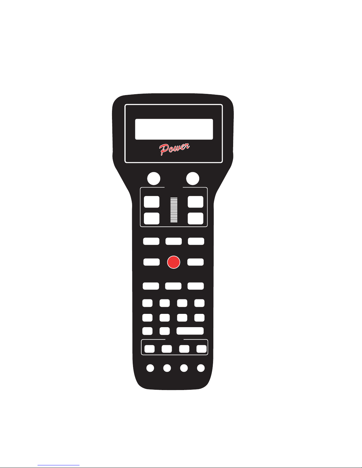
Power CabTM BUTTON NUMBERING SCHEME
DCC COMPATIBLE COMMAND CONTROL
1 2
3 4
5 6
7 8 9
LOC:1234
FWD: 000
12:00AM
L1-3---
10 11 12
13 14 15
16 17 18 19
20 21 22 23
24
25
26 27 28 29
30 31
32
9
NCE
CAB
22
Page 23
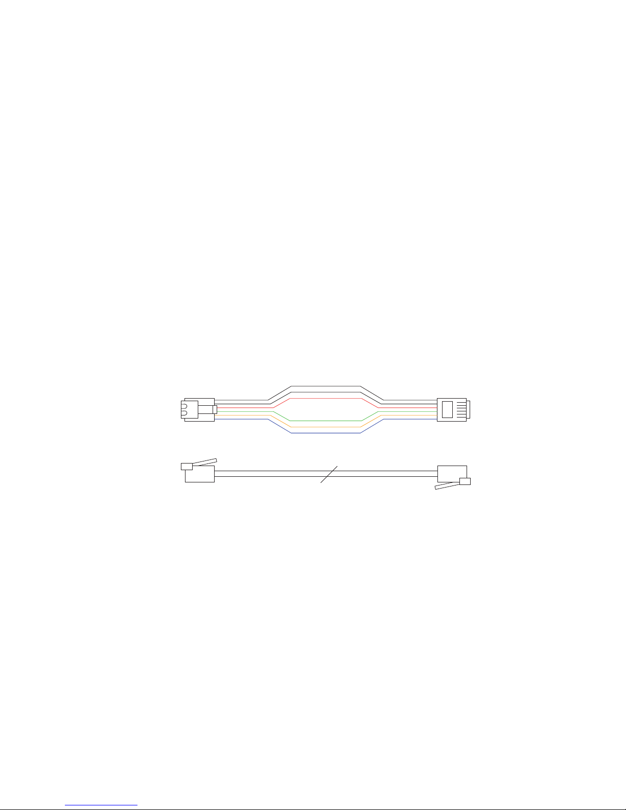
TABLE OF FACTORY DEFAULT VALUES
White
Black
Red
Green
Yellow
Blue
Cab bus cable
Pin 1 Pin 1
General RJ type cable connection
FOR “SHIFTED” KEYS
Key # Value ..... Description Key # Value ... Description
1 ...... 67........ Direction 17 .... 96 ...... Assign Loco -> Cab
2 ...... 94 ........ Brake 18 .... 98 ...... Set Clock
3 ...... 90 ........ Increment 4/10 steps 19 .... 99 ...... Use Program Track
4 ...... 74 ........ Increment 1 Step 20 ... 100 ..... Setup Command Station
5 ...... 91........ Decrement 4/10 steps 21 ... 101 ..... Setup Cab Parameters
6 ...... 75 ........ Decrement 1 Step 22 ... 118 ..... Reserved
7 ..... 123 .......reserved 23 ... 102 ..... Setup Macros
8 ...... 81 ........ Headlight 24 ... 108 ..... Reserved
9 ..... 122 ....... reserved 25 ... 119 ..... Reserved
10 .... 125 ....... reserved 26 ... 103 ..... Setup Old Consist
11.... 116 .......reserved 27 ... 108 ..... Reserved
12.... 109 .......reserved 28 ... 120 ..... Reserved
13.... 121 .......reserved 29 ... 115 ..... Reserved
14.... 117 .......reserved 30 ... 112 ..... Function 10
15.... 111 .......Momentum 31 ... 113 ..... Function 11
16..... 97 ........ Program on Main 32 ... 114 ..... Function 12
6 WIRE CAB BUS CABLE WITH RJ-12 CONNECTORS
Pin # Color Description
Pin 1 ...... White.............. Power to track
Pin 2 ...... Black.............. Ground
Pin 3 ...... Red ................ - RS-485
Pin 4 ...... Green ............ + RS-485
Pin 5 ...... Yellow............ +12 volts
Pin 6 ...... Blue................Power to track
23
Page 24
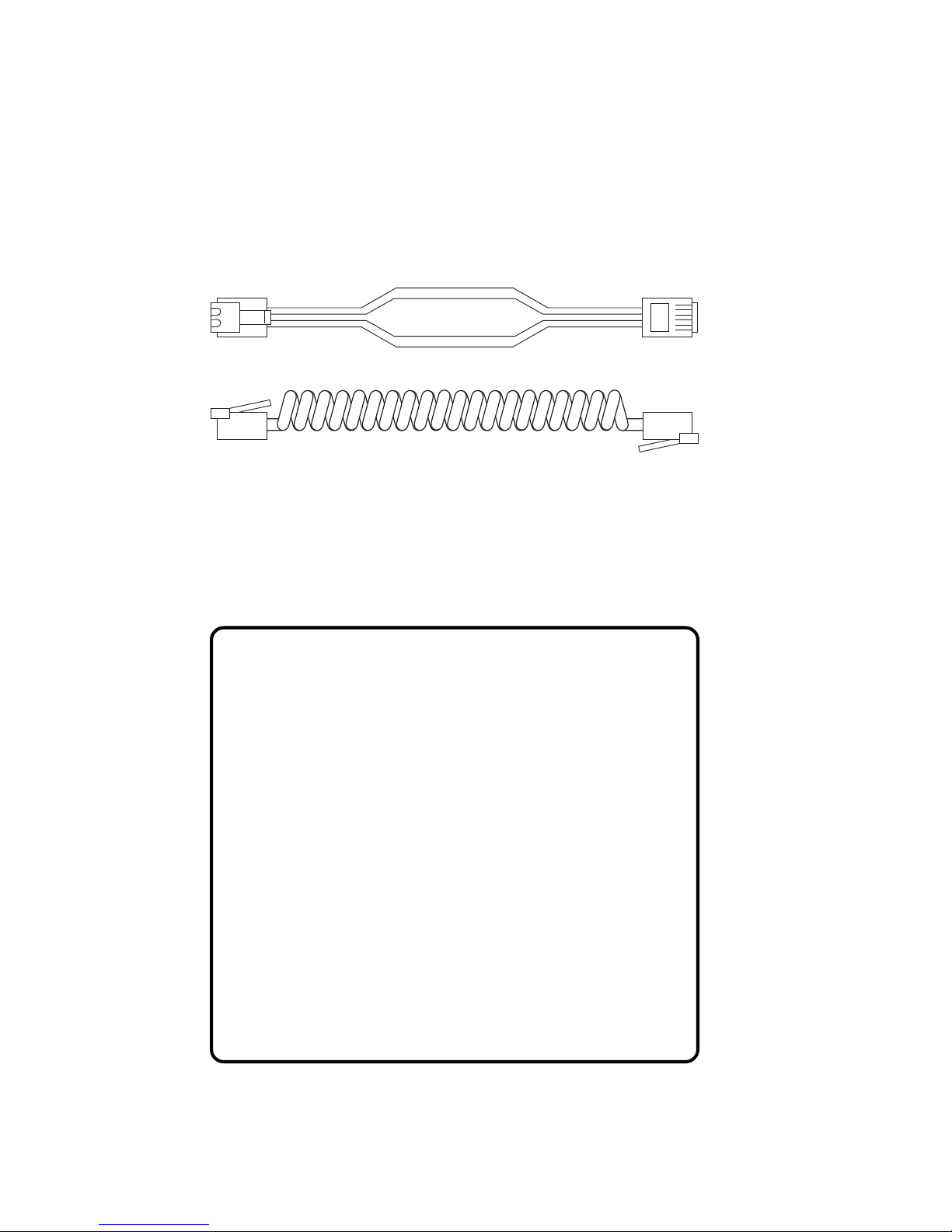
4 WIRE CAB BUS CABLE WITH RJ-12 CONNECTORS
Black
Red
Green
Yellow
Cab bus cable
Pin 1 Pin 1
General RJ type cable connection
**To prevent potential damage, ALWAYS use 4 wire cables when your Power
Cab is used as a Pro Cab. This keeps Power Cab track power from interferring
with the NCE cab bus.
Pin # Color Description
Pin 1 ...... White.............. Unused
Pin 2 ...... Black.............. Ground
Pin 3 ...... Red ................ - RS-485
Pin 4 ...... Green ............ + RS-485
Pin 5 ...... Yellow............ +12 volts
Pin 6 ...... Blue................Unused
NOTE: Pro Cab mode cables only need the center four wires for proper operation.
Power CabTM Specifications:
Power Input Requirements: 10-15V regulated DC, 3A maximum
Power Connector: 5.5mm x 2.5mm center positive
Track Power Output: Voltage input minus (-) .5 Volt 2 Amps peak
Cabs: 2 maximum plus USB Interface and/or Mini Panel
Number of simultaneous trains: 12
Number of consists: 16 advanced consists of unlimited number of
locomotives each. Plus 4 old style consists up to 2 locos each.
Range of locomotive addresses: 0-9999
Range of consist addresses: 112-127
Range of accessory addresses: 1-2044
Range of signal addresses: 1-2044
Computer interface: USB optional
Pro CabTM Mode Specifications:
When the Power Cab is used as a Pro Cab, the following specifications
apply.
Size: 8-3/4 x 3-5/8” x 1”
Power Requirements: 8 VDC 40mA (backlight off) 8 VDC 120mA
(backlight on)
Replacement Encoder: Bournes or Digikey part #3315C-1-006
Speed control: Thumbwheel operated digital encoder with adjustable
ballistic tracking rate. Pushbutton speed control with adjustable auto-repeat
rate (4 pulses per second to one pulse per 4 seconds).
Backlit LCD Display: 2 line by 16 characters/line. Two extra display lines
available for display of additional information when used with computer
dispatcher programs.
24
Page 25
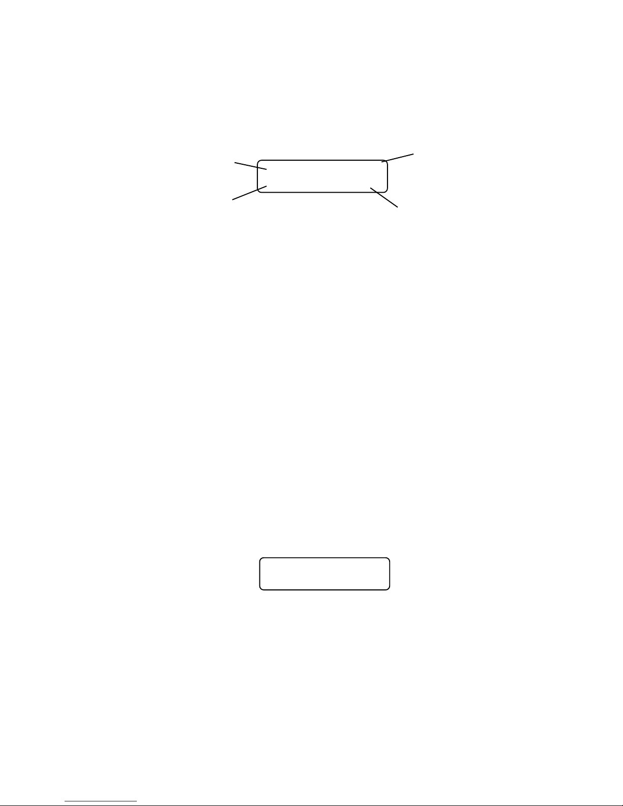
OPERATING PROCEDURES
THE “NORMAL” DISPLAY
Loco or consist
currently being
controlled
Speed step
and direction
of current
loco
LOC:1234 2:00PM
FWD:108 L1-3---
Current time
from system
fast clock or
display of
track current
Status of locomotive
decoder functions
TOP ROW OF DISPLAY
LOC: Indicates that a locomotive is being operated.
CON: Indicates that a consist is being operated.
2:00PM: Scale Time in either 12 hour or 24 hour format.
BOTTOM ROW OF DISPLAY
FWD: or REV: Indicates the current direction of loco or consist
108 - Indicates the speed step to which the active loco/consist is presently set.
L123456 or - - - - - - Indicates which function outputs are ON. Those outputs that are OFF are displayed
as dashes (-). The example above indicates that the Headlight, Function #1 and
Function #3 are on.
Other status information may temporarily be displayed is this area.
SELECTING A LOCOMOTIVE OR
CONSIST
First a word about locomotive addresses. A decoder can have 2 different addresses,
the Short Address (values from 1-127) and the Long Address (sometimes called 4
digit with a range of 0000-9999). A decoder can use one or the other but not both at
the same time. Some entry level decoders can only use the Short Address.
As you can see above there is an overlap in the address ranges between the short
and long address. You can have a Long Address of 6 and a Short Address of 6.
They are not the same. To use a short address (range 1-127) it is selected on the
cab by entering only the significant digits (no zeros before you get to the numbers).
To enter a long address in the range of 0-127 put a zero before the digits. A long
address between 0 and 127 will have an asterisk (*) before the loco address on the
cab display as below:
LOC:*006 2:00PMLOC:*006 2:00PM
LOC:*006 2:00PM
LOC:*006 2:00PMLOC:*006 2:00PM
ENTER LOCO: _ENTER LOCO: _
ENTER LOCO: _
ENTER LOCO: _ENTER LOCO: _
NOTE: You will notice that the short address 0 is not available but the long address 0
is listed as a valid address. Short address 0 is the “broadcast” address for DCC. If
you were to send commands to short address 0 all locomotives on the layout would
respond causing chaos. For this reason we don’t allow use of short address 0. Long
address 0 can be used just like any other locomotive address.
25
Page 26

To select a locomotive for operation:
l Press the SELECT LOCO button
l Enter the 1 to 4 digit address of the loco/consist to be operated. A “Leading
Zero” is necessary for long addresses below 128. An asterisk will be displayed
before any long address below 128 (example below).
l Press the ENTER key.
Locomotive address examples:
4421 = Long Address
006 = Long Address as entered.
*006 = Long Address as displayed
45 = Short Address as entered
045 = Short Address as displayed
LOC: will be displayed when addressing a single locomotive
CON: will be displayed when addressing a Consist.
CONTROLLING HEADLIGHTS AND
OTHER DECODER FUNCTIONS
Pressing HEADLIGHT will alternately toggle the headlight of the locomotive on and
off.
To toggle other functions simply press the number key that corresponds to the
function you wish to control. E.g. - The ‘1’ key controls function 1.
Your cab will display which functions are on and off on the lower right of the display.
The letter ‘L’ stands for Headlight (Function 0) and numbers 1-6 stand for functions
1-6 (functions 7 through 12 are not displayed on the cab but work if you push the
buttons). In the example below the headlight plus functions 2 and 6 are on.
26
LOC:4449 xx:xxPMLOC:4449 xx:xxPM
LOC:4449 xx:xxPM
LOC:4449 xx:xxPMLOC:4449 xx:xxPM
FWD:02 L-2---6FWD:02 L-2---6
FWD:02 L-2---6
FWD:02 L-2---6FWD:02 L-2---6
Page 27

OLD AND ADVANCED CONSISTS
EXPLAINED
Before setting up any consist an explanation is needed to understand the operating
differences between Advanced and Old Style consists (also called brute force or
Universal). Basic decoders that have a short address but no CONSIST address
(Early Lenz, MRC 30x/31x series and Digitrax 120 series Decoders) can not be
used with advanced consisting.
ADVANCED CONSISTS
Decoders that support advanced consisting have an additional short address, the
CONSIST address, in addition to their normal Long and Short addresses. The
consist address is stored in CV19 and can have a value of 112-127.
A decoder considers itself in a consist if the Consist Address (CV19) is something
other than 0 or 128. A decoder is added to a consist when the command station
sends a command to set the consist address in the decoder to the consist number.
The decoder will now use this new consist address for speed and direction
commands. This has many advantages including the need for fewer communications
on the track and no need for the operator or command station to keep track of which
locomotives are in what consist on the layout.
Each locomotive in an advanced consist will still respond to function or programming
commands using the original locomotive address. This means the operator can turn
lights or other functions on or off for each locomotive individually.
To kill an entire consist, a command is broadcast on the tracks for each decoder
with that consist number to clear its consist address and return to individual
operation. Locomotives can also be individually dropped from a consist. You can also
add locomotives to a consist after the initial set up of that consist.
Advanced style consists can easily be taken from layout to layout and they will
continue to operate as a single unit.
OLD STYLE CONSISTS (also called brute force or
Universal)
With an Old Style consist, the command station keeps track of each locomotive in
the consist within the memory of the command station. Each speed change of the
cab generates a separate speed command to each of the decoders in the consist.
These extra speed commands on the track have significant ramifications if you have
a lot of consists operating at one time as in a club situation. The effect is to slow
down locomotive response to the throttle speed controls.
Use this method of building a consist with MRC and Digitrax 120 series decoders.
Decoders in an old style consist have no knowledge of being in a consist and will not
operate as a unit when moved to another layout. You can add one or more advanced
consists to any old style consist.
SETTING UP AN ADVANCED CONSIST
To set up a consist press SETUP. This screen allows you to choose the type of
consist to be created. For those consists that will contain advanced decoders, press
ENTER to select the advanced mode.
CONSIST 2:00PMCONSIST 2:00PM
CONSIST 2:00PM
CONSIST 2:00PMCONSIST 2:00PM
ENTER=ADV 1=OLDENTER=ADV 1=OLD
ENTER=ADV 1=OLD
ENTER=ADV 1=OLDENTER=ADV 1=OLD
An advanced consist has no limit to the number of loco’s assigned.
NOTE: you can not setup, add, or delete a loco from a consist while the locomotive
is moving. It must be at speed 0. Decoders will not accept consist commands while
they are in motion. This prevents reception of false consist make/break commands
due to electrical noise generated by the wheels rolling on the track.
27
Page 28

CONSIST ADDRESS:
The consist address can be any number from 112 through 127. The system will
suggest the first available consist address (the priority is highest to lowest). Press
ENTER to accept this address.
SETUP 2:00PMSETUP 2:00PM
SETUP 2:00PM
SETUP 2:00PMSETUP 2:00PM
CON ADDR: 127CON ADDR: 127
CON ADDR: 127
CON ADDR: 127CON ADDR: 127
You may enter any other number you wish (from 112 to 127) then press the ENTER
key. If you have locomotives on the layout using short addresses make sure you
don’t pick an address already in use. This is one reason to use long addresses with
your loco fleet. It will keep the short addresses free for consists.
ENTERING THE LEAD LOCO NUMBER
Entering the lead loco number is optional but recommended. The command station
keeps track of consists by their lead loco number. The locomotive is the loco that the
command station will send function commands to. For example: headlight on/off
commands. If the command station did not know the lead loco it would not know
which locomotive should have the headlight turned on or off.
The lead loco number also acts as an alias for the consist number entered above.
Say you have a bunch of consists stored on staging tracks and you wish to operate
one of them. After the consist is set up, you can select the consist by pressing SEL
LOCO then entering either the lead loco number or the consist number. The lead
loco number is typically easiest to remember because it is the number printed right
on the locomotive. The consist address may not relate to any visible or easily
remembered number.
SETUP 2:00PMSETUP 2:00PM
SETUP 2:00PM
SETUP 2:00PMSETUP 2:00PM
LEAD LOCO: _LEAD LOCO: _
LEAD LOCO: _
LEAD LOCO: _LEAD LOCO: _
Enter the lead loco number followed by pressing the ENTER key.
ENTERING THE LEAD LOCO DIRECTION
If the locomotive is to operate in the forward direction press ENTER. Press the
DIRECTION key if you wish to have the locomotive operate in the reverse direction.
Subsequent presses of the DIRECTION key will keep changing the direction. When
you get the direction you desire press the ENTER key.
CONSIST 2:00PMCONSIST 2:00PM
CONSIST 2:00PM
CONSIST 2:00PMCONSIST 2:00PM
DIR THIS LOCO: FDIR THIS LOCO: F
DIR THIS LOCO: F
DIR THIS LOCO: FDIR THIS LOCO: F
This informs the decoder whether the loco is in the line-up facing forward or reverse.
For instance, in an A-B-A consist the lead A unit and the B unit will be setup in the
Forward direction, and the second A unit will be setup in the Reverse direction.
ENTERING THE REAR LOCO NUMBER
Entering the rear loco number is optional. The command station keeps track of
consists by their lead or rear loco number. If you select the consist by the rear loco
number the direction of the consist will be reversed from the direction of operation if
you selected it by the lead loco. You don’t have to enter a rear loco number if you
don’t need/want to operate the consist in reverse. The rear loco number also act as
an alias for the consist number just as the lead loco number.
SETUP 2:00PMSETUP 2:00PM
SETUP 2:00PM
SETUP 2:00PMSETUP 2:00PM
REAR LOCO: _REAR LOCO: _
REAR LOCO: _
REAR LOCO: _REAR LOCO: _
28
Page 29

Enter the rear loco number followed by the ENTER key.
NOTE: If you plan on dropping the rear loco from the consist later on, DO NOT enter
it as the rear loco. Enter it later on when prompted for mid-consist locos.
ENTERING THE REAR LOCO DIRECTION
If the locomotive is to operate in the normal direction press ENTER. Press the
DIRECTION key if you wish to have the locomotive operate in the reverse direction.
Subsequent presses of the DIRECTION key will keep changing the direction. When
you get the direction you desire press the ENTER key.
CONSIST 2:00PMCONSIST 2:00PM
CONSIST 2:00PM
CONSIST 2:00PMCONSIST 2:00PM
DIR THIS LOCO: FDIR THIS LOCO: F
DIR THIS LOCO: F
DIR THIS LOCO: FDIR THIS LOCO: F
ADDING A MID-CONSIST LOCO
At this point you can start to add more locomotives to the consist. Enter the next
locomotive (decoder address) followed by pressing the ENTER key. If you don’t
want to add any more locomotives to the consist just press ENTER.
CONSIST 2:00PMCONSIST 2:00PM
CONSIST 2:00PM
CONSIST 2:00PMCONSIST 2:00PM
ADD LOCO: _ADD LOCO: _
ADD LOCO: _
ADD LOCO: _ADD LOCO: _
ENTERING THE LOCO’S DIRECTION
CONSIST 2:00PMCONSIST 2:00PM
CONSIST 2:00PM
CONSIST 2:00PMCONSIST 2:00PM
DIR THIS LOCO: FDIR THIS LOCO: F
DIR THIS LOCO: F
DIR THIS LOCO: FDIR THIS LOCO: F
As with the lead locomotive, this informs the decoder if the loco is in the line-up facing
forward or reverse.
If the locomotive is to operate in the normal direction press ENTER. Press the
DIRECTION key if you wish to have the locomotive operate in the reverse direction.
Subsequent presses of the DIRECTION key will keep changing the direction. When
you get the direction you desire press the ENTER key.
At this point you will be prompted to add additional locomotives. If you don’t want to
add any more locomotives to the consist just press ENTER or PROG/ESC with out
entering an address.
DROPPING A LOCOMOTIVE FROM AN ADVANCED
CONSIST
To delete a consist locomotive press DEL
DEL LOCO 2:00PMDEL LOCO 2:00PM
DEL LOCO 2:00PM
DEL LOCO 2:00PMDEL LOCO 2:00PM
ENTER LOCO: _ENTER LOCO: _
ENTER LOCO: _
ENTER LOCO: _ENTER LOCO: _
This will drop the loco identified from whatever consist it was part of. There is no
need to know the consist number for this operation. You cannot drop a lead or rear
loco without clearing the entire consist. Deleting a loco sets CV19 to a value of 0 in
that loco.
ADDING A LOCO TO AN ADVANCED CONSIST
Select the consist.
ADD LOCO 2:00PMADD LOCO 2:00PM
ADD LOCO 2:00PM
ADD LOCO 2:00PMADD LOCO 2:00PM
CONSIST ADDR: _CONSIST ADDR: _
CONSIST ADDR: _
CONSIST ADDR: _CONSIST ADDR: _
Press ADD . Enter the address of the consist, or lead loco, to which the loco is to be
added and then press the ENTER key.
29
Page 30
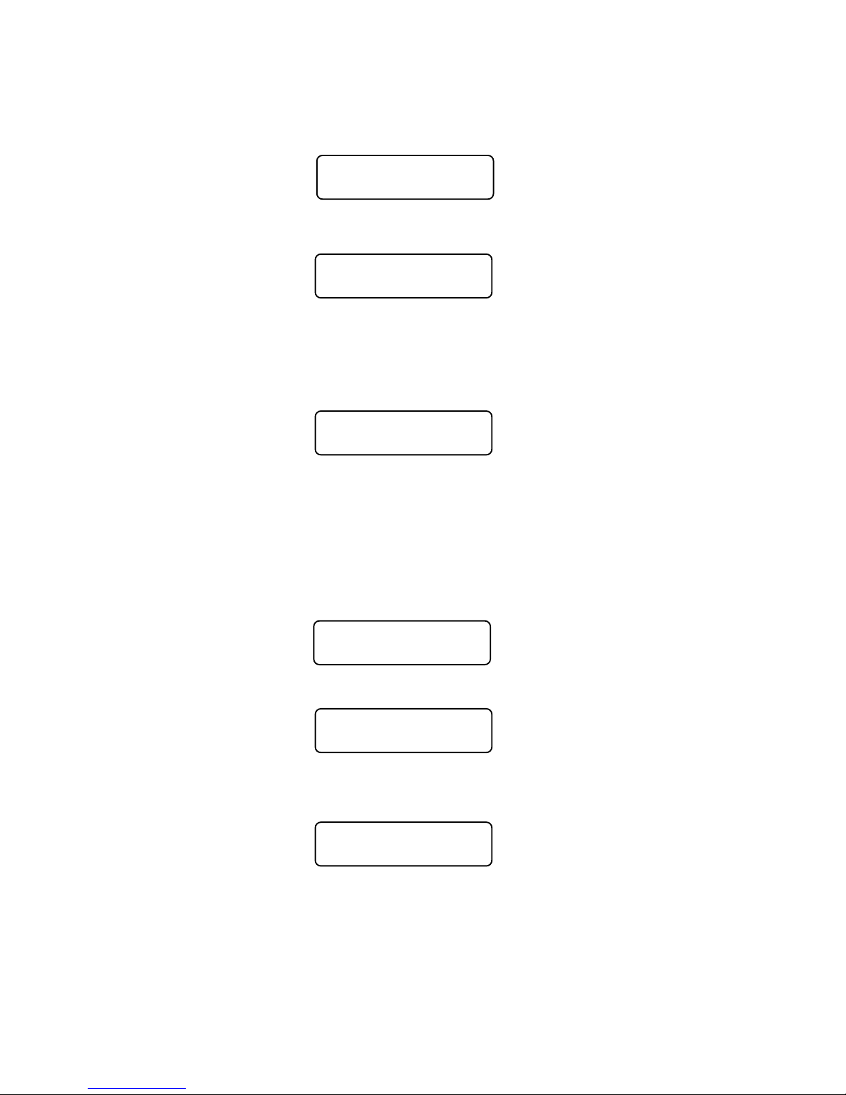
ADD LOCO 2:00PMADD LOCO 2:00PM
ADD LOCO 2:00PM
ADD LOCO 2:00PMADD LOCO 2:00PM
ADD LOCO: _ADD LOCO: _
ADD LOCO: _
ADD LOCO: _ADD LOCO: _
Enter the loco number to be added and press the ENTER key.
Enter the loco’s direction
CONSIST 2:00PMCONSIST 2:00PM
CONSIST 2:00PM
CONSIST 2:00PMCONSIST 2:00PM
DIR THIS LOCO: FDIR THIS LOCO: F
DIR THIS LOCO: F
DIR THIS LOCO: FDIR THIS LOCO: F
If the loco is to operate in the normal direction press ENTER, otherwise press the
DIRECTION key followed by pressing the ENTER key. This informs the decoder
whether the locomotive is in the line-up facing reverse.
CLEARING AN ADVANCED CONSIST
Press CLEAR. Select the consist to be cleared.
LOC:4449 2:00PMLOC:4449 2:00PM
LOC:4449 2:00PM
LOC:4449 2:00PMLOC:4449 2:00PM
KILL CONSIST: _KILL CONSIST: _
KILL CONSIST: _
KILL CONSIST: _KILL CONSIST: _
Enter the lead or rear loco number and press ENTER. This sends a command to all
decoders with this consist address to clear the consist address from the decoder.
You can also enter the consist address if you know it. All locomotives that were
assigned to this consist will no longer respond to the consist address.
CHANGING THE LEAD/REAR LOCO
Under some circumstances it is desirable to change which locomotive is to act as
the lead loco of a consist. One of these circumstances is when you want to drop the
lead/rear loco from the consist. The command station will not allow you to drop the
lead/rear loco so you will want to assign a new locomotive as lead/rear. Then you will
be able to drop the old lead loco.
SETUP 2:00PMSETUP 2:00PM
SETUP 2:00PM
SETUP 2:00PMSETUP 2:00PM
CON ADDR: _CON ADDR: _
CON ADDR: _
CON ADDR: _CON ADDR: _
The first step is to press SETUP. Then enter either the consist number of the current
lead loco number (address). Then press ENTER.
SETUP 2:00PMSETUP 2:00PM
SETUP 2:00PM
SETUP 2:00PMSETUP 2:00PM
LEAD LOCO: _LEAD LOCO: _
LEAD LOCO: _
LEAD LOCO: _LEAD LOCO: _
Enter the new lead loco number and press ENTER. If the new lead loco is to operate
in the forward direction press ENTER. Press the DIRECTION key if you wish to have
the locomotive operate in the reverse direction. When you get the direction you
desire press the ENTER key.
CONSIST 2:00PMCONSIST 2:00PM
CONSIST 2:00PM
CONSIST 2:00PMCONSIST 2:00PM
DIR THIS LOCO: FDIR THIS LOCO: F
DIR THIS LOCO: F
DIR THIS LOCO: FDIR THIS LOCO: F
You are now finished changing the lead locomotive of the consist.
Use a similar procedure to change the rear loco.
30
Page 31

OLD STYLE CONSISTS
SETUP AN OLD STYLE CONSIST
CONSIST 2:00PMCONSIST 2:00PM
CONSIST 2:00PM
CONSIST 2:00PMCONSIST 2:00PM
ENTER=ADV 1=OLDENTER=ADV 1=OLD
ENTER=ADV 1=OLD
ENTER=ADV 1=OLDENTER=ADV 1=OLD
Press SETUP. This screen allows you to choose the type of consist to be created.
For those consists that will contain any basic decoders, press 1. Please note that the
limit on an old style consist is two locomotives or advanced consists. NOTE: Once
you setup an old style consist you will not be able to select a new locomotive to run
unless you store the consist away by pressing recall (or clear the consist). Each cab
may have up to 2 old style consists in recall.
INITIAL SCREEN DISPLAY
OLD TYPE 2:00PMOLD TYPE 2:00PM
OLD TYPE 2:00PM
OLD TYPE 2:00PMOLD TYPE 2:00PM
CON: 000 000CON: 000 000
CON: 000 000
CON: 000 000CON: 000 000
This screen is “informational” to show all 4 “slots” for loco’s in the Old Style consist.
Press the ENTER key to continue.
ENTERING THE LEAD LOCO NUMBER
OLD TYPE 2:00PMOLD TYPE 2:00PM
OLD TYPE 2:00PM
OLD TYPE 2:00PMOLD TYPE 2:00PM
LEADLEAD
LOCO: _ LOCO: _
LEAD
LOCO: _
LEADLEAD
LOCO: _ LOCO: _
Enter the loco number followed by the ENTER key. The first loco to be added will be
the lead loco (the lead loco number will be displayed on the screen during normal
operation). The consist will respond to this number.
ENTERING THE LOCO DIRECTION
OLD TYPE 2:00PMOLD TYPE 2:00PM
OLD TYPE 2:00PM
OLD TYPE 2:00PMOLD TYPE 2:00PM
DIR THIS LOCO: FDIR THIS LOCO: F
DIR THIS LOCO: F
DIR THIS LOCO: FDIR THIS LOCO: F
The locomotive direction is assumed to be forward, if it is to operate in reverse press
the DIRECTION key. This informs the command station the loco is in the line-up
facing reverse. This affects only the direction of the loco, not lighting. Press the
ENTER key to continue.
ADD REAR LOCO
OLD TYPE 2:00PMOLD TYPE 2:00PM
OLD TYPE 2:00PM
OLD TYPE 2:00PMOLD TYPE 2:00PM
REAR LOCO: _REAR LOCO: _
REAR LOCO: _
REAR LOCO: _REAR LOCO: _
Enter the second loco address followed by the ENTER key.
31
Page 32

ENTERING THE LOCO DIRECTION
OLD TYPE 2:00PMOLD TYPE 2:00PM
OLD TYPE 2:00PM
OLD TYPE 2:00PMOLD TYPE 2:00PM
DIR THIS LOCO: FDIR THIS LOCO: F
DIR THIS LOCO: F
DIR THIS LOCO: FDIR THIS LOCO: F
The locomotive direction is assumed to be forward, if it is to operate in reverse press
the DIRECTION key. This informs the command station whether the loco is in the
line-up facing reverse. This affects only the direction of the loco, not lighting. Press
the ENTER key to continue.
This operation leaves the consist as the active unit for this Cab. By pressing
RECALL the operator can change to another loco/consist but the old style consist
will stay with this Cab until it is either passed to another Cab (by assigning it) or the
consist is cleared.
OLD STYLE CONSIST FULL
OLD TYPE 2:00PMOLD TYPE 2:00PM
OLD TYPE 2:00PM
OLD TYPE 2:00PMOLD TYPE 2:00PM
CONSIST NOW FULLCONSIST NOW FULL
CONSIST NOW FULL
CONSIST NOW FULLCONSIST NOW FULL
The consist contains two loco’s which is the maximum amount that we support in this
style of consist. Press the ENTER key to continue.
CLEARING AN OLD STYLE CONSIST
KILL? 02:00PMKILL? 02:00PM
KILL? 02:00PM
KILL? 02:00PMKILL? 02:00PM
ENTER=NO 1=YES:ENTER=NO 1=YES:
ENTER=NO 1=YES:
ENTER=NO 1=YES:ENTER=NO 1=YES:
Press 1 to clear the consist from the Command Station memory. All locomotives that
were in the consist may now be selected and operated independently.
VIEWING WHICH LOCOS ARE IN AND OLD STYLE
CONSIST
Press SETUP - The locos and their direction will be displayed. Press ENTER to
return to normal operation.
32
Page 33

CONTROLLING TURNOUTS AND
OTHER ACCESSORIES
ENTER THE ACCESSORY NUMBER TO BE OPERATED
CONTROL 02:00PMCONTROL 02:00PM
CONTROL 02:00PM
CONTROL 02:00PMCONTROL 02:00PM
ACC NUMBER: _ACC NUMBER: _
ACC NUMBER: _
ACC NUMBER: _ACC NUMBER: _
Press the SELECT ACCY key. Enter the address of the accessory to be operated.
Followed by pressing the ENTER key. Valid accessory addresses range from 1 to
2044.
TURN ACCESSORY ON OR OFF
ACC: 003 02:00PMACC: 003 02:00PM
ACC: 003 02:00PM
ACC: 003 02:00PMACC: 003 02:00PM
1=N(ON) 2=R(OFF)1=N(ON) 2=R(OFF)
1=N(ON) 2=R(OFF)
1=N(ON) 2=R(OFF)1=N(ON) 2=R(OFF)
Press 1 to turn accessory ON. (Switch machine set to Normal)
Press 2 to turn accessory OFF. (Switch machine set to Reverse)
Note: If you are going to activate the same accessory, just “double-clicking” the
SELECT ACCY key will activate it.
33
Page 34

THE MOMENTUM BUTTON
When you press the momentum button you are prompted to enter a momentum level.
There are 9 levels of momentum (1-9) plus ‘direct drive’(0). Pressing a digit button
from 0-9 will automatically set the acceleration and deceleration rates of the
locomotive(s) being controlled.
Pressing 0 sets the momentum of the train to 0 effectively turning it off. 1 is the
smallest amount of momentum, 9 is the most.
If you are operating an Advanced or Old Style consist setup in the command station
all locomotives will have their momentum set. If an Old Style consist includes one or
more Advanced consists all locomotives in the Advanced consist (up to 6 per
advanced consist) will also have their momentum set properly.
Technical stuff - what happens when you set momentum
The digit entered is multiplied by 8 (factory default) and sent to CV3. The value
sent to CV4 is ½ the value sent to CV3. You can change these multipliers.
You can setup the following momentum parameters in the SET CMD STA menu:
The acceleration multiplier can be set to a value in the range of 0-25.
The deceleration can be set to FULL or HALF the value sent to CV3.
You can disable the sending of momentum commands to consists.
If a decoder follows NMRA Recommended Practice 9.2.2 the rates will be as shown
below with the factory default settings (multiplier = 8 and deceleration = half).
Rate 1 = 7 seconds to full speed, 3 seconds to stop
Rate 2 = 14 seconds to full speed, 7 seconds to stop
Rate 3 = 21 seconds to full speed, 10 seconds to stop
Rate 4 = 28 seconds to full speed, 14 seconds to stop
Rate 5 = 35 seconds to full speed, 17 seconds to stop
Rate 6 = 42 seconds to full speed, 21 seconds to stop
Rate 7 = 49 seconds to full speed, 24 seconds to stop
Rate 8 = 54 seconds to full speed, 27 seconds to stop
Rate 9 = 61 seconds to full speed, 30 seconds to stop
If a consist is active when MOMENTUM is pressed the button will do nothing unless
“CONSIST MOMENTUM” is enabled (factory default) in the SET CMD STA menu.
Momentum commands will be sent to a limit of 6 locos per Advanced consist.
Notes regarding momentum commands and decoders:
There are special commands for setting consist momentum (CV23 and CV24) but
most decoders do not support these CV’s.
CV3 and CV4 are required and have standardized values in decoders per RP-9.2.2.
Support for consist CV23 and CV24 is not required in decoders, this is why we use
CV3 and CV4 for consist momentum..
Sound equipped locomotives that verbally speak the value of CVs must be turned off
by setting CV 62 to a value of 0 for momentum to work properly. Setting CV 62 to a
value of 1 turns the verbal response back on.
Some European makes of decoders require locomotive power to be interrupted
before the new CV vales will take effect.
34
Page 35

USING MACROS TO CONTROL
TURNOUTS
MACROS EXPLAINED
Macros are really a list of turnouts controlled by accessory decoders that you wish
to operate as a group. There are a total of 16 macros, each one capable of
controlling up to 8 turnouts. Macros may be ‘chained’ with other macros to create
complex routes with hundreds of turnouts.
ENTER THE MACRO NUMBER TO BE EXECUTED
LOC: 1023 2:00PMLOC: 1023 2:00PM
LOC: 1023 2:00PM
LOC: 1023 2:00PMLOC: 1023 2:00PM
MACRO NUMBER: _MACRO NUMBER: _
MACRO NUMBER: _
MACRO NUMBER: _MACRO NUMBER: _
l Press MACRO key.
l Enter the number of the macro (0-16) to be executed
l Press ENTER.
MACRO NOT SET UP
ERROR: 02:00PMERROR: 02:00PM
ERROR: 02:00PM
ERROR: 02:00PMERROR: 02:00PM
-MACRO IS EMPTY--MACRO IS EMPTY-
-MACRO IS EMPTY-
-MACRO IS EMPTY--MACRO IS EMPTY-
This message will be displayed if no macro has been programmed for the number
entered.
MACRO PROGRAMMING
To program a macro see the PROGRAMMING MACRO section, page 59.
35
Page 36
PROGRAMMING
PROCEDURES
ACCESSING PROGRAMMING MODES
To access the various programming modes, press the PROG/ESC key. The
following messages will be displayed for each press of the PROG/ESC key. When
the desired mode is displayed, press the ENTER key to enter that mode. To quickly
get to a programming mode, press the PROG/ESC key and then press the number
of the screen. If you have pressed the PROG/ESC key by mistake, or want to exit
out without having to press the PROG/ESC key several times, press EXPN.
Refer to the following sections for the individual programming instructions. To escape
from any programming session press the PROG key.
To program locomotive decoders on
the main (OPS mode) press ENTER.
To assign a locomotive/consist to a
Cab press ENTER. [2]
To start, stop, or set the System Clock
press ENTER [3]
To program on the program track press
ENTER. [4]
To set command station parameters
press ENTER. [5]
To set the Cab parameters press
ENTER. [6]
To program accessory decoders on the
main press ENTER. [7]
To setup macros (routing through
turnouts) press ENTER. [8]
SEL MODE 02:00PMSEL MODE 02:00PM
SEL MODE 02:00PM
SEL MODE 02:00PMSEL MODE 02:00PM
PROGRAM ON MAINPROGRAM ON MAIN
PROGRAM ON MAIN
PROGRAM ON MAINPROGRAM ON MAIN
SEL MODE 02:00PMSEL MODE 02:00PM
SEL MODE 02:00PM
SEL MODE 02:00PMSEL MODE 02:00PM
ASSIGN LOCO->CABASSIGN LOCO->CAB
ASSIGN LOCO->CAB
ASSIGN LOCO->CABASSIGN LOCO->CAB
SEL MODE 02:00PMSEL MODE 02:00PM
SEL MODE 02:00PM
SEL MODE 02:00PMSEL MODE 02:00PM
SET SYSTEM CLOCKSET SYSTEM CLOCK
SET SYSTEM CLOCK
SET SYSTEM CLOCKSET SYSTEM CLOCK
SEL MODE 02:00PMSEL MODE 02:00PM
SEL MODE 02:00PM
SEL MODE 02:00PMSEL MODE 02:00PM
USE PROGRAM TRKUSE PROGRAM TRK
USE PROGRAM TRK
USE PROGRAM TRKUSE PROGRAM TRK
SEL MODE 02:00PMSEL MODE 02:00PM
SEL MODE 02:00PM
SEL MODE 02:00PMSEL MODE 02:00PM
SET CMD STATIONSET CMD STATION
SET CMD STATION
SET CMD STATIONSET CMD STATION
SEL MODE 02:00PMSEL MODE 02:00PM
SEL MODE 02:00PM
SEL MODE 02:00PMSEL MODE 02:00PM
SET CAB PARAMSSET CAB PARAMS
SET CAB PARAMS
SET CAB PARAMSSET CAB PARAMS
SEL MODE 02:00PMSEL MODE 02:00PM
SEL MODE 02:00PM
SEL MODE 02:00PMSEL MODE 02:00PM
PROG ACCESSORIESPROG ACCESSORIES
PROG ACCESSORIES
PROG ACCESSORIESPROG ACCESSORIES
SEL MODE 02:00PMSEL MODE 02:00PM
SEL MODE 02:00PM
SEL MODE 02:00PMSEL MODE 02:00PM
PROGAM MACROSPROGAM MACROS
PROGAM MACROS
PROGAM MACROSPROGAM MACROS
To browse through all the advanced
consists in the system, press ENTER [9]
To program signals on the main press
ENTER. [10]
36
SEL MODE 02:00PMSEL MODE 02:00PM
SEL MODE 02:00PM
SEL MODE 02:00PMSEL MODE 02:00PM
BROWSE CONSISTSBROWSE CONSISTS
BROWSE CONSISTS
BROWSE CONSISTSBROWSE CONSISTS
SEL MODE 02:00PMSEL MODE 02:00PM
SEL MODE 02:00PM
SEL MODE 02:00PMSEL MODE 02:00PM
PROGRAM SIGNALSPROGRAM SIGNALS
PROGRAM SIGNALS
PROGRAM SIGNALSPROGRAM SIGNALS
Page 37

PROGRAMMING MENUS
TABLE OF CONTENTS
The following is a chart of all of the programming modes and each section within
each mode. Refer to the details in the following sections.
PROGRAMMING ON THE MAIN ............................................................................ 37
WHAT TO PROGRAM ......................................................................................... 37
ADDRESS PROGRAMMING (OPTION 1) ......................................................... 37
CV PROGRAMMING (OPTION 2) ...................................................................... 38
SET DECODER CONFIGURATION (OPTION 3) ............................................. 38
SET MOTOR CONTROL PARAMETERS (OPTION 4) ..................................... 39
SET UP DECODER OUTPUT/FUNCTION MAPPING (OPTION 5) ................ 41
SET UP NCE LIGHTING EFFECTS (OPTION 6) .............................................. 42
QSI PROGRAMMING (OPTION 8) ..................................................................... 43
BINARY CV PROGRAMMING (OPTION 9) ....................................................... 43
ASSIGNING A LOCO TO A CAB ............................................................................ 44
ASSIGN THE LOCO ............................................................................................. 44
ASSIGN THE CAB ................................................................................................. 44
SET THE SYSTEM CLOCK...................................................................................... 44
STOPPING THE CLOCK ..................................................................................... 44
SETTING 12 OR 24 HOUR MODE ..................................................................... 44
ENTERING THE HOUR ....................................................................................... 44
ENTERING THE MINUTE .................................................................................... 45
ENTERING THE RATIO ....................................................................................... 45
STARTING THE CLOCK ...................................................................................... 45
PROGRAMMING TRACK ........................................................................................ 46
PROGRAMMING OPTIONS ................................................................................ 46
STANDARD PROGRAMMING (OPTION 1) ....................................................... 47
DECODER MANUFACTURER ........................................................................ 47
DECODER VERSION ....................................................................................... 47
DISPLAY OF ACTIVE ADDRESS .................................................................... 48
ENTERING THE DECODER ADDRESS ........................................................ 48
SETTING UP BASIC DECODER CONFIGURATION (CV29) ...................... 48
DIRECTION BIT ............................................................................................ 49
SPEED STEPS .............................................................................................. 49
ANALOG MODE ........................................................................................... 49
SPEED TABLE SELECTION ........................................................................ 49
ENABLE LONG OR SHORT ADDRESS ..................................................... 49
SETTING UP MOTOR CONTROL PARAMETERS ....................................... 50
START VOLTAGE ........................................................................................ 50
MAXIMUM VOLTAGE ................................................................................... 50
MID SPEED ................................................................................................... 50
ACCELERATION .......................................................................................... 50
DECELERATION .......................................................................................... 51
MOTOR PWM FREQUENCY ...................................................................... 51
NCE TORQUE COMPENSATION KICK RATE ......................................... 51
NCE TORQUE COMPENSATION KICK DEPTH ....................................... 51
SET UP DECODER FUNCTION MAPPING ................................................... 52
SET ANY CV (OPTION 2) .................................................................................... 53
REGISTER PROGRAMMING (OPTION 3) ........................................................ 53
PAGED PROGRAMMING (OPTION 4) .............................................................. 54
DIRECT PROGRAMMING (OPTION 5) ............................................................. 54
SET UP NCE LIGHTING EFFECTS (OPTION 6) .............................................. 54
RECOVERY PROGRAMMING (OPTION 7) ...................................................... 54
DECODER UNLOCK OPTION 8 ......................................................................... 55
SETUP COMMAND STATION ................................................................................. 55
DISPLAY SOFTWARE VERSION AND DATE .................................................... 55
37
Page 38

NUMBER OF STOP PACKETS ........................................................................... 55
NUMBER OF TEMP PACKETS ........................................................................... 55
NUMBER OF ACCESSORY PACKETS .............................................................. 56
NUMBER OF HORN OFF PACKETS ................................................................. 56
NUMBER OF PROGRAM PACKETS .................................................................. 56
SEND FUNCTION COMMANDS TO CONSIST ADDRESS ............................. 56
CONSIST MOMENTUM ....................................................................................... 56
MOMENTUM MULTIPLIER .................................................................................. 56
MOMENTUM DECELERATION RATE ................................................................ 57
FUNCTION REFRESH RATE .............................................................................. 57
SYSTEM RESET ................................................................................................... 57
SET CAB PARAMETERS ......................................................................................... 57
SHOW TRACK CURRENT ................................................................................... 57
NUMBER OF RECALLS ....................................................................................... 58
ANALOG HORN CHANNEL ................................................................................. 58
ANALOG AUX. CHANNEL ................................................................................... 58
ANALOG BIAS ....................................................................................................... 58
ASSIGNING THE BELL FUNCTION ................................................................... 58
PROGRAM ACCESSORY DECODERS ................................................................. 59
PROGRAM MACROS ............................................................................................... 59
LINKING MACROS ............................................................................................... 60
BROWSE CONSISTS ............................................................................................... 61
PROGRAM SIGNAL DECODERS ........................................................................... 61
38
Page 39

PROGRAMMING ON THE MAIN
Programming on the Main is also called Operations (OPS) Mode programming. OPS
programming allows you to change parameters while the loco is on the main track
(even while it’s running). This does not affect other locomotives on the track. You
can even change the locomotive address.
OPS PROG 02:00PMOPS PROG 02:00PM
OPS PROG 02:00PM
OPS PROG 02:00PMOPS PROG 02:00PM
PROG LOCO: 003PROG LOCO: 003
PROG LOCO: 003
PROG LOCO: 003PROG LOCO: 003
We first begin by telling the system which locomotive to program. If you want to
program the locomotive you are currently operating just press ENTER. If you wish to
program a different locomotive just enter its address at the above prompt.
WHAT TO PROGRAM
After determining which locomotive you wish to program you will see the following
display. The Power CabTM system provides 9 different OPs mode programming
options.
LOC:1022 02:00PMLOC:1022 02:00PM
LOC:1022 02:00PM
LOC:1022 02:00PMLOC:1022 02:00PM
1=ADR 2=CV 3=CFG1=ADR 2=CV 3=CFG
1=ADR 2=CV 3=CFG
1=ADR 2=CV 3=CFG1=ADR 2=CV 3=CFG
The first three options are displayed. Press ENTER to see more options. For
example: If you wish to set the locomotive address press 1, if you want to program
CVs press 2.
Descriptions of each programming option are described below.
1 ............................. SET UP LOCOMOTIVE ADDRESS
2 ............................. CHANGE ANY CV IN THE DECODER
3 ............................. SET UP THE DECODER CONFIGURATION (CV29)
4 ............................. MOTOR CONTROL
5 ............................. FUNCTION MAP
6 ............................. NCE EFFECTS
7 ............................. Not Used
8 ............................. QSI SOUND
9 ............................. BIN
ADDRESS PROGRAMMING (Option 1)
This option provides a means by which to program the address of your locomotive.
Most decoders allow programming of the locomotive address while on the mainline.
The first thing to do is decide if you want to program a long or short address into the
locomotive.
SET ADDR 03:38PMSET ADDR 03:38PM
SET ADDR 03:38PM
SET ADDR 03:38PMSET ADDR 03:38PM
1=LONG 2=SHORT1=LONG 2=SHORT
1=LONG 2=SHORT
1=LONG 2=SHORT1=LONG 2=SHORT
In DCC there are 2 kinds of addresses (loco numbers), long and short. Short
addresses range from 1 to 127 and long addresses range from 0-9999. We normally
recommend using long addresses for all your locomotives. Consists require the use
of a short address so it is better to conserve short addresses by using long
addresses for individual locomotives. Push the digit button that corresponds to the
type of address you wish to program. You will then be presented with the display
below.
SET ADDR 03:38PMSET ADDR 03:38PM
SET ADDR 03:38PM
SET ADDR 03:38PMSET ADDR 03:38PM
LONG ADDR: _LONG ADDR: _
LONG ADDR: _
LONG ADDR: _LONG ADDR: _
39
Page 40

Enter the new address for the locomotive. The new address will be sent to the
locomotive and you will be returned to the normal display with the locomotive
selected and ready to run. Most decoders allow programming the address while on
the mainline. If you are using a locomotive with a sound decoder from QSI you will
need to turn off verbal programming acknowledgment (set CV62 to 0) for the
address to be set properly. If your locomotive does not allow setting the address on
the mainline you will need to set it on the programming track. You can press PROG/
ESC to escape out of setting the address without affecting anything in the decoder.
No commands are sent until you press ENTER after typing in the address.
CV PROGRAMMING FOR MOBILE, LOCOMOTIVE
DECODERS (Option 2)
This option allows you to change any configuration variable (range of 1-999) in your
mobile locomotive decoder.
ENTER CONFIGURATION VARIABLE NUMBER
All configuration variables can be set while on the mainline. Just pressing ENTER
without typing in a number will return you to the main OPS programming prompt.
Pressing PROG/ESC will completely exit from programming and return you to the
normal display.
PROG CV 02:00PMPROG CV 02:00PM
PROG CV 02:00PM
PROG CV 02:00PMPROG CV 02:00PM
ENTER CV NUM: _ENTER CV NUM: _
ENTER CV NUM: _
ENTER CV NUM: _ENTER CV NUM: _
ENTER THE VALUE
The value to be programmed into the CV should now be entered at the prompt below.
Pressing PROG/ESC before or during number entry will completely exit from
programming and return you to the normal display.
PROG CV 02:00PMPROG CV 02:00PM
PROG CV 02:00PM
PROG CV 02:00PMPROG CV 02:00PM
ENTER VALUE: _ENTER VALUE: _
ENTER VALUE: _
ENTER VALUE: _ENTER VALUE: _
SET DECODER CONFIGURATION (Option 3)
This option will setup the various decoder configuration parameters. There are six of
these parameters squeezed into one CV. You will be asked a series of questions
regarding the basic operation of the locomotive. If you are in doubt about the proper
answer just press ENTER and you will usually be OK.
DIRECTION BIT - NORMAL OR REVERSE
Press ENTER for the locomotive to operate in the normal direction or press 1 to
switch the direction of operation.
DIR BIT? 02:00PMDIR BIT? 02:00PM
DIR BIT? 02:00PM
DIR BIT? 02:00PMDIR BIT? 02:00PM
ENTER=NORM 1=REVENTER=NORM 1=REV
ENTER=NORM 1=REV
ENTER=NORM 1=REVENTER=NORM 1=REV
SPEED STEPS - 28 OR 14
Press ENTER. All decoders made since 1997 support 28 speeds. NOTE: If you are
wondering how to set the decoder for 128 speed operation, you do not have to
program anything. 128 speed mode is always enabled in decoders that support 128
speed step operation.
SPEED 02:00PMSPEED 02:00PM
SPEED 02:00PM
SPEED 02:00PMSPEED 02:00PM
ENTER=28 1=14 _ENTER=28 1=14 _
ENTER=28 1=14 _
ENTER=28 1=14 _ENTER=28 1=14 _
40
Page 41
DC (Analog) MODE
Press ENTER to turn DC operation mode off, press 1 to turn DC mode on. We
recommend leaving DC mode off for most layouts. This is to prevent all your
locomotives from taking off at once in case of a failure in your power station or
someone accidentally connecting the track to a DC power supply (it happens
more often than you might think).
DC MODE 02:00PMDC MODE 02:00PM
DC MODE 02:00PM
DC MODE 02:00PMDC MODE 02:00PM
ENTER=NO 1=YES_ENTER=NO 1=YES_
ENTER=NO 1=YES_
ENTER=NO 1=YES_ENTER=NO 1=YES_
ADVANCED ACKNOWLEDGE
Press ENTER to turn Advanced Acknowledge mode off, press 1 to turn Advanced
Acknowledge mode on.
ADV ACK? 02:00PMADV ACK? 02:00PM
ADV ACK? 02:00PM
ADV ACK? 02:00PMADV ACK? 02:00PM
ENTER=NO 1=YES _ENTER=NO 1=YES _
ENTER=NO 1=YES _
ENTER=NO 1=YES _ENTER=NO 1=YES _
NOTE: advanced acknowledgment is not operational in any decoders at this time
as the NMRA has not defined how it is to work.
SPEED TABLE SELECTION
If the Standard Speed Table is to be used, press ENTER. If the Alternate
(uploadable) Speed Table in the decoder is to be used, press 1.
SPEEDTBL 02:00PMSPEEDTBL 02:00PM
SPEEDTBL 02:00PM
SPEEDTBL 02:00PMSPEEDTBL 02:00PM
ENTER=STD 1=ALT_ENTER=STD 1=ALT_
ENTER=STD 1=ALT_
ENTER=STD 1=ALT_ENTER=STD 1=ALT_
ENABLE LONG OR SHORT ADDRESS
The short address is used when operating on DCC systems that do not use long
addresses.
ADDRESS 02:00PMADDRESS 02:00PM
ADDRESS 02:00PM
ADDRESS 02:00PMADDRESS 02:00PM
ENTER=S 1=LONG:_ENTER=S 1=LONG:_
ENTER=S 1=LONG:_
ENTER=S 1=LONG:_ENTER=S 1=LONG:_
SET MOTOR CONTROL PARAMETERS (Option 4)
This option can be used to setup the various locomotive motor speed control
parameters. You can skip adjusting any of these parameters (CVs) by pressing
ENTER without entering The first adjustment is:
START VOLTAGE (CV2)
Start voltage is the amount of voltage the decoder sends to the motor when a
speed step 1 command is sent to the locomotive. This is some extra voltage to
help get the motor running. You can put in any value from 0-255. If you put in a
value of 10 then 10/255 (about 4%) of the full motor voltage will be applied to the
motor at speed step 1.
OPS PROG 11:22AMOPS PROG 11:22AM
OPS PROG 11:22AM
OPS PROG 11:22AMOPS PROG 11:22AM
START VOLTS: _START VOLTS: _
START VOLTS: _
START VOLTS: _START VOLTS: _
In most decoders the start voltage is added to each speed step. A good way to
setup the Start Voltage is to first set your throttle to speed 1 then go into this Start
Voltage programming and try different values until you get the desired starting
speed. This approach can be used with most of the motor speed adjustments. You
may exit programming at any time by pressing PROG/ESC.
41
Page 42
MAXIMUM VOLTAGE (CV5)
This is the amount of voltage applied to the motor at full speed. A value of 255 means
send the full available track voltage to the motor. Lower numbers will tell the decoder
to send proportionally less voltage when full speed is called for.
OPS PROG 11:22AMOPS PROG 11:22AM
OPS PROG 11:22AM
OPS PROG 11:22AMOPS PROG 11:22AM
MAX VOLTAGE: _MAX VOLTAGE: _
MAX VOLTAGE: _
MAX VOLTAGE: _MAX VOLTAGE: _
A value of 192 will cut the maximum speed to 192/255 (about 75%) of the track
voltage. Most decoders interpret a value of 0 to mean 255.
MID SPEED VOLTAGE (CV6)
This is the amount of voltage applied to the motor when the middle speed step (14 or
64 depending on speed mode) is requested. A value of 128 means to send about ½
the available track voltage (128/255 of the voltage) to the motor.
OPS PROG 11:22AMOPS PROG 11:22AM
OPS PROG 11:22AM
OPS PROG 11:22AMOPS PROG 11:22AM
MID VOLTAGE: _MID VOLTAGE: _
MID VOLTAGE: _
MID VOLTAGE: _MID VOLTAGE: _
Lower or higher values will send proportionally higher or lower voltages at mid-speed.
Most decoders interpret a value of 0 to mean 128.
ACCELERATION (CV3)
With this CV set to 0 the decoder will be in what is commonly called ‘direct drive’. The
decoder will instantly jump to the speed requested by the throttle. You can add
momentum by adjusting this parameter. See also MOMENTUM BUTTON, Page 14.
OPS PROG 11:22AMOPS PROG 11:22AM
OPS PROG 11:22AM
OPS PROG 11:22AMOPS PROG 11:22AM
ACCELERATION: _ACCELERATION: _
ACCELERATION: _
ACCELERATION: _ACCELERATION: _
A value of 1 will force a delay of .007 seconds between speed steps in 128 speed
mode (.032 seconds in 28 speed mode). This is equivalent to .896 seconds (.007 x
128 speeds) to go from speed 0 to full speed. A value of 10 will yield about 8.9
seconds to full speed.
DECELERATION (CV4)
Deceleration works to delay the slowing down of the motor with the same timing as
acceleration.
OPS PROG 11:22AMOPS PROG 11:22AM
OPS PROG 11:22AM
OPS PROG 11:22AMOPS PROG 11:22AM
DECELERATION: _DECELERATION: _
DECELERATION: _
DECELERATION: _DECELERATION: _
MOTOR PWM FREQUENCY (CV9)
DCC decoders almost always drive the motor of the locomotive with Pulse Width
Modulation (PWM). This is a series of full voltage pulses that vary in width from very
narrow for low motor speed to very wide providing higher power to the motor. How
often the pulses are sent is called the frequency.
OPS PROG 11:22AMOPS PROG 11:22AM
OPS PROG 11:22AM
OPS PROG 11:22AMOPS PROG 11:22AM
PWM FREQ: _PWM FREQ: _
PWM FREQ: _
PWM FREQ: _PWM FREQ: _
The frequency is adjustable on some decoders. Settings for this CV vary so consult
your decoder manual for the proper value. If your decoder is capable of ‘silent’
operation usually a 0 is required.
42
Page 43

NCE TORQUE COMPENSATION (Dither) KICK RATE
(CV116)
Newer NCE decoders (V3.5+) provide Torque Compensation for smooth low speed
operation. Torque Compensation gives a steady stream of ‘kicks’ to the motor when
running at very low speeds. You can adjust how often the motor is kicked (Kick
Rate) and how hard it is kicked (Kick Strength). CV116 controls the rate.
OPS PROG 11:22AMOPS PROG 11:22AM
OPS PROG 11:22AM
OPS PROG 11:22AMOPS PROG 11:22AM
KICK RATE: _KICK RATE: _
KICK RATE: _
KICK RATE: _KICK RATE: _
The typical value is 2-4 with the maximum practical value of about 6. The smaller the
number the more often the motor gets a brief voltage kick. A value of 0 turns off the
kick. A value of 1 gives continuous kicks to the motor (not very useful). When using
Torque Compensation set the Start Voltage to 0 for best operation.
NCE TORQUE COMPENSATION (Dither) KICK DEPTH
(CV117)
This is how hard the motor is kicked at low speed. Typical values range from 1 to 40.
High quality motors (Kato) need very little kick strength where lower quality motors
such as old Athearn and LifeLike need relatively large values (30-50) for slow speed
crawling,
OPS PROG 11:22AMOPS PROG 11:22AM
OPS PROG 11:22AM
OPS PROG 11:22AMOPS PROG 11:22AM
KICK DEPTH: _KICK DEPTH: _
KICK DEPTH: _
KICK DEPTH: _KICK DEPTH: _
Tips for setting up T/C (Torque Compensation):
·Start by setting the locomotive speed to 1 on your throttle.
·Set the Kick Rate to 4.
·Set the Kick Depth to 20 then adjust this value up or down until the locomotive just
barely crawls.
It may be easier to set the T/C with the body shell removed from the locomotive so
that you can see the flywheels turn. When you get fairly good slow speed operation
go back to the Kick Rate and try bumping the value up by 1 or 2 to see if the
operation improves.
DECODER OUTPUT/FUNCTION MAPPING
(Option 5)
General Discussion of function mapping
Function mapping is used to customize which lighting outputs (or sound effects) are
controlled by which function keys on your handheld throttle. Each function command,
F0 through F12, is assigned a unique CV that allows the corresponding function
command to be redirected to up to 14 different lighting outputs or sound effects.
A single function key can control more than one output if desired.
It is also possible for one output to be controlled by multiple function keys. In this
case, the output will be turned on when any of the corresponding function keys are
active. That output will turn off only when all relevant inputs have also been turned
off.
Note that all function commands cannot be mapped to all outputs. The LCD display
on your Power CabTM will indicate only those outputs that can be mapped to each
function command.
The F0 function has two CVs - one for forward direction and one for reverse.
Function outputs mapped to these CVs will be directional unless the same output is
mapped to both CVs. CVs 33 and 34 are both for the F0 function.
43
Page 44
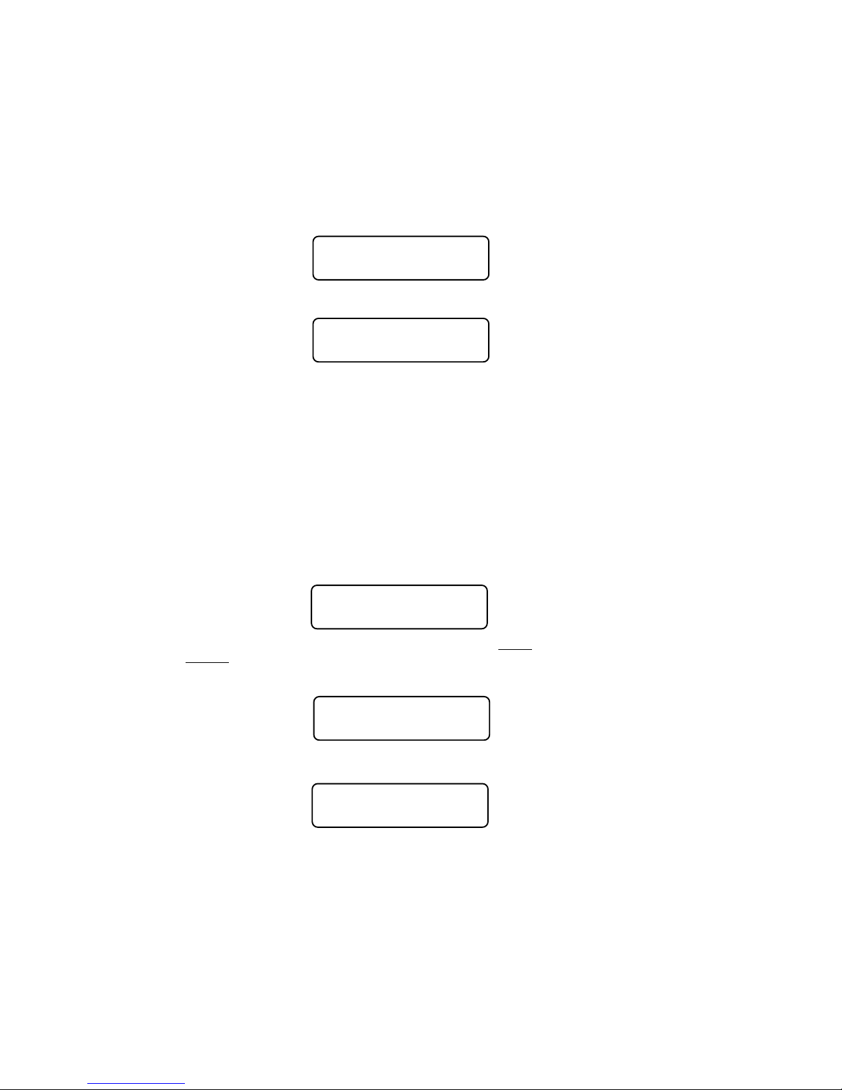
On NCE decoders CV33 and CV34 do not provide directionality (see SETUP NCE
LIGHTING EFFECTS below) but otherwise operate the same as above. With NCE
decoders direction of operation for function outputs is provided by the lighting effects
CVs 120 through 127.
Lenz and TCS decoders do not follow NMRA standard function mapping procedures.
When you select function mapping you are prompted for the function number to map.
PRESS FUNCTIONPRESS FUNCTION
PRESS FUNCTION
PRESS FUNCTIONPRESS FUNCTION
NUMBER TO MAPNUMBER TO MAP
NUMBER TO MAP
NUMBER TO MAPNUMBER TO MAP
The top line of the LCD displays the function number and the output numbers that
can be controlled by the function.
F2 12345678F2 12345678
F2 12345678
F2 12345678F2 12345678
OUTPUTS: —4——OUTPUTS: —4——
OUTPUTS: —4——
OUTPUTS: —4——OUTPUTS: —4——
Pressing a digit key will enable the output on the decoder when the function is
activated. Pressing the same digit key again will disable the output. In the display
above the 4 key has been pressed so that output number 4 will activate when ever
the F2 button is pressed on your handheld cab. If you were to press another digit
such a 6, both output 4 and output 6 will be controlled by pressing F2.
When mapping functions higher than 3, the top line of the LCD will use small numbers
to indicate the output numbers 10 through 14. To enable/disable these high numbers
press the digit key that is 10 less than the output number. Example: press 0 for
output 10, 1 for output 11, etc. Pressing PROG/ESC will exit from mapping at any
time.
SETUP NCE LIGHTING EFFECTS (Option 6)
You can use this option to customize the lighting effects for your NCE decoder
equipped locomotives. This programming option will only work with NCE decoders.
NCE EFX 07:04NCE EFX 07:04
NCE EFX 07:04
NCE EFX 07:04NCE EFX 07:04
OUTPUT NUMBER:_OUTPUT NUMBER:_
OUTPUT NUMBER:_
OUTPUT NUMBER:_OUTPUT NUMBER:_
Function outputs are numbered from 1 to 14. Do not confuse Output numbers with
Function numbers. The headlight is always output 1 and the reverse light is usually
output 2. You are prompted for the output number to setup. Press the output number
followed by ENTER.
OUTPUT NUMBER:03OUTPUT NUMBER:03
OUTPUT NUMBER:03
OUTPUT NUMBER:03OUTPUT NUMBER:03
USE THUMBWHEEL USE THUMBWHEEL
USE THUMBWHEEL
USE THUMBWHEEL USE THUMBWHEEL
Use the thumbwheel or up/down speed buttons to scroll through the different lighting
effect options. Press ENTER when you get the one you want.
DIR OF OPERATIONDIR OF OPERATION
DIR OF OPERATION
DIR OF OPERATIONDIR OF OPERATION
1=FW 2=RV 3=BOTH1=FW 2=RV 3=BOTH
1=FW 2=RV 3=BOTH
1=FW 2=RV 3=BOTH1=FW 2=RV 3=BOTH
Next press 1,2 or 3 to select the ‘directionality’ of the output. If you want the output
active only in the forward direction of travel - press 1. Press 2 for the effect to
operate only when travelling in reverse. 3 activates the output no matter which
direction the locomotive is travelling.
44
Page 45

REGULAR BULB ORREGULAR BULB OR
REGULAR BULB OR
REGULAR BULB ORREGULAR BULB OR
LED 1=BULB 2=LEDLED 1=BULB 2=LED
LED 1=BULB 2=LED
LED 1=BULB 2=LEDLED 1=BULB 2=LED
Last, press 1 if the output has a regular incandescent bulb attached. Press 2 if the output
has an LED connected. LEDs behave differently when dimmed than incandescent bulbs.
Pressing 1 or 2 informs the decoder which set of lighting characteristics to use for this
output.
QSI PROGRAMMING (Option 8)
QSI sound decoders use indexed programming of CV51,CV52,and CV56. You are
asked for an index number before you are asked for the CV value. CV49 is then
automatically set with the index value before the original CV is set with the desired
data.
When programming CV56 you are asked for primary and secondary index numbers
before you are asked for the CV value. CV49 and CV50 are then automatically set
with the index numbers before CV53 is set with the desired data.
All other CV’s are programmed in the normal manner.
BINARY CV PROGRAMMING (Option 9)
Use this option if you need to build up the value for a CV bit-by-bit. Enter the CV
number you wish to program.
BIN PROG 02:10AMBIN PROG 02:10AM
BIN PROG 02:10AM
BIN PROG 02:10AMBIN PROG 02:10AM
ENTER CV NUM: _ENTER CV NUM: _
ENTER CV NUM: _
ENTER CV NUM: _ENTER CV NUM: _
Then press bit number (top line of LCD has bit numbers) to toggle the corresponding
individual bits on the lower line of the LCD that make up a binary byte. In the example
below the 1, 3 and 7 keys have been pressed to set the corresponding bits in the
byte. To set the value of a bit back to 0 press the bit number again.
CV: 060 76543210CV: 060 76543210
CV: 060 76543210
CV: 060 76543210CV: 060 76543210
BITS: 10001010BITS: 10001010
BITS: 10001010
BITS: 10001010BITS: 10001010
When you get the value built up to the number you desire, press ENTER to program
the CV.
45
Page 46
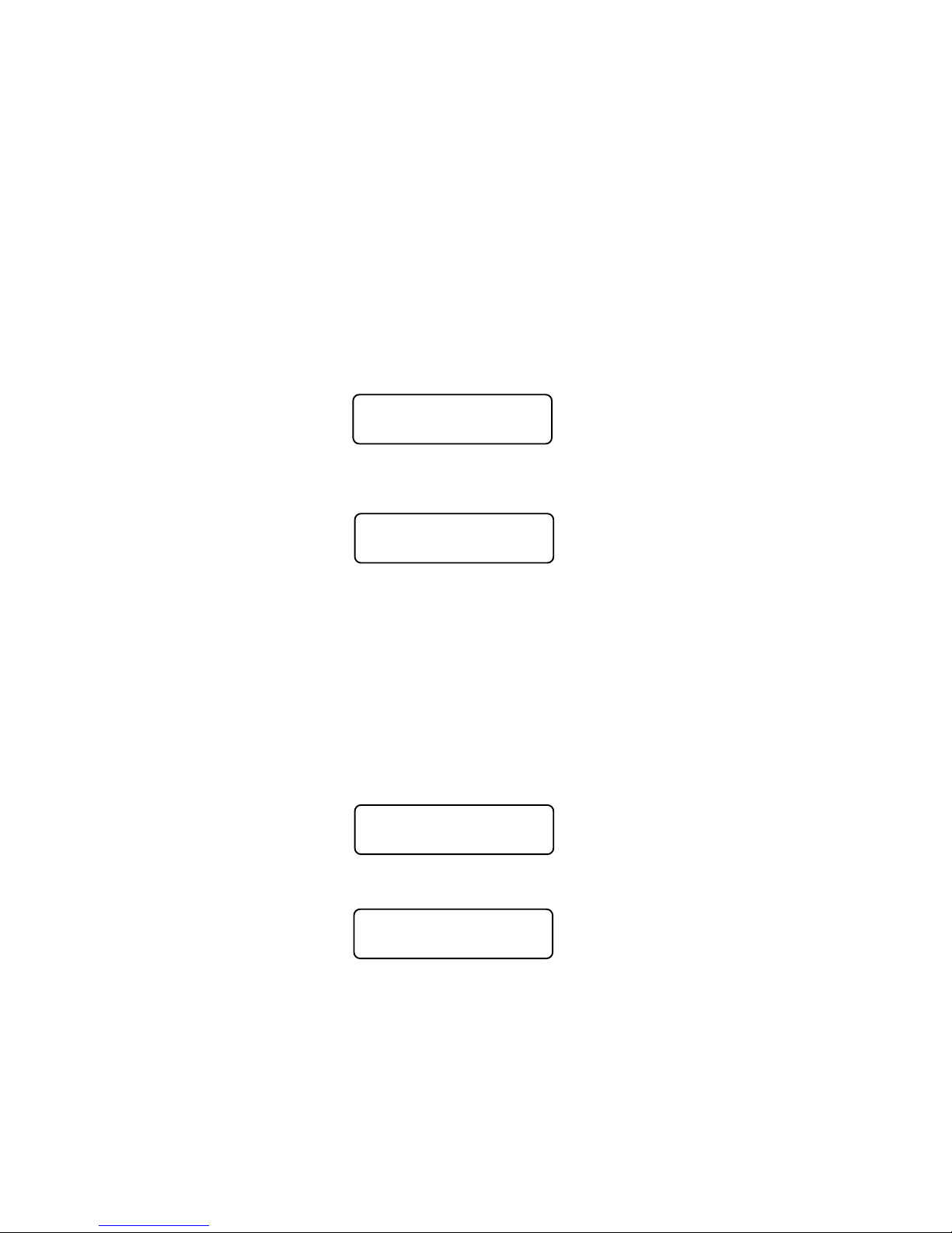
ASSIGNING A LOCO TO A CAB
(shortcut = PROG 2 )
This selection passes a loco or consist from one cab to another. This is especially
useful when the other operator is a novice or has a Basic Cab. The locomotive/
consist is passed to the assigned cab and the locomotive/consist controlled by the
other cab is passed back to the original cab. In effect the locomotives controlled by
the cabs are “swapped”. This way you will not accidentally ‘lose’ a locomotive in the
system.
ASSIGN THE LOCO
Enter the loco/consist number you want to assign to another cab, then press
ENTER. If you want to assign the loco you are currently running just push ENTER.
ASSIGN 02:00PMASSIGN 02:00PM
ASSIGN 02:00PM
ASSIGN 02:00PMASSIGN 02:00PM
WHICH LOCO: _003WHICH LOCO: _003
WHICH LOCO: _003
WHICH LOCO: _003WHICH LOCO: _003
ASSIGN THE CAB
You need to know the address of the cab you want to ‘receive’ the loco you are
assigning. Enter the Cab number then press ENTER.
LOC:1234 02:00PMLOC:1234 02:00PM
LOC:1234 02:00PM
LOC:1234 02:00PMLOC:1234 02:00PM
TO WHICH CAB? _TO WHICH CAB? _
TO WHICH CAB? _
TO WHICH CAB? _TO WHICH CAB? _
This operation is also useful to transfer an old style consist to a smaller cab without
the capability of setting up consists.
SET THE SYSTEM CLOCK
(shortcut = PROG 3)
This allows the operator to start/stop the clock, set it, choose 12 or 24 hour
operation, or change the fast clock ratio.
STOPPING THE CLOCK
Press 1 to stop the clock, press ENTER to leave the clock running and continue with
clock programming. If the clock is already stopped, you will be prompted to start it.
STOP? 02:00PMSTOP? 02:00PM
STOP? 02:00PM
STOP? 02:00PMSTOP? 02:00PM
ENTER=NO 1=STOPENTER=NO 1=STOP
ENTER=NO 1=STOP
ENTER=NO 1=STOPENTER=NO 1=STOP
SETTING 12 or 24 HOUR MODE
Press 1 for 12 hour mode, press ENTER for 24 hour mode.
SET TIME 02:00PMSET TIME 02:00PM
SET TIME 02:00PM
SET TIME 02:00PMSET TIME 02:00PM
1=12HR 2=24HR _1=12HR 2=24HR _
1=12HR 2=24HR _
1=12HR 2=24HR _1=12HR 2=24HR _
ENTERING THE HOUR
Enter the starting hour in 24 hour format. For times in the A.M. use 0 to 11. For times
in the P.M. use 12 to 23. Press ENTER.
46
Page 47

SET TIME 02:00PMSET TIME 02:00PM
SET TIME 02:00PM
SET TIME 02:00PMSET TIME 02:00PM
ENTER HOURS: _ENTER HOURS: _
ENTER HOURS: _
ENTER HOURS: _ENTER HOURS: _
ENTERING THE MINUTE
Enter the starting minute. Use 0 through 59. Press ENTER.
SET TIME 02:00PMSET TIME 02:00PM
SET TIME 02:00PM
SET TIME 02:00PMSET TIME 02:00PM
ENTER MINUTES: _ENTER MINUTES: _
ENTER MINUTES: _
ENTER MINUTES: _ENTER MINUTES: _
ENTERING THE RATIO
Enter the ratio that the clock should run at with 1 being the normal speed. The ratio
can be any number from 1 (1:1) to 15 (15:1). Press ENTER.
SET TIME 02:00PMSET TIME 02:00PM
SET TIME 02:00PM
SET TIME 02:00PMSET TIME 02:00PM
ENTER RATIO: _ENTER RATIO: _
ENTER RATIO: _
ENTER RATIO: _ENTER RATIO: _
STARTING THE CLOCK
If the clock was stopped, entering SET THE SYSTEM CLOCK will display this screen
to let you start (or restart) the clock. Press 1 to start the clock, press ENTER to
leave the clock stopped and continue with clock programming (see above).
START? 02:00PMSTART? 02:00PM
START? 02:00PM
START? 02:00PMSTART? 02:00PM
ENTER=NO 1=STARTENTER=NO 1=START
ENTER=NO 1=START
ENTER=NO 1=STARTENTER=NO 1=START
47
Page 48

USE PROGRAM TRACK
(shortcut = PROG 4)
Locomotive decoders remember their operating parameters such as the address,
start voltage and lighting effect setups in the decoder’s memory. Each storage
location is called a Configuration Variable, or CV for short. There is usually a CV for
each programmable parameter. The Power CabTM allows you to change any or all
of the CVs in the loco, including the address. These variables will remain as
programmed until you change them. Programming on the Main (covered earlier in
this manual) is very useful for modifying one, two or a few CVs while the locomotive
is out on the layout. The Program Track is useful for more intensive initial setup of a
locomotive. The biggest advantage of the program track is the ability to read out the
values of CVs already setup in the locomotive decoder.
Please note: The programming track does not supply enough power to run your
locomotive. You can only run trains on the main track. We recommend that you
always try out a newly installed decoder on the Program Track first. If you can ‘read’
a decoder on the Program Track you can reasonably expect that it is wired correctly
and working properly.
PROGRAMMING OPTIONS
Just as with Programming on the Main there are several menu options you can
select. The Power CabTM system provides 7 different Program Track options.
Descriptions of each programming option are described below.
1 = STANDARD DECODER SETUP, including
Address, Configuration and Function Mapping.
2 = CHANGE ANY CV IN THE DECODER
Reads and programs CVs 1-999.
3 = SET UP THE DECODER CONFIGURATION (CV29)
Change direction of operation, analog mode on/off, 14 or 28 speed mode,
long or short address, factory or custom speed table.
4 = PAGED MODE PROGRAMMING
Force the system to use paged mode programming.
5 = DIRECT MODE PROGRAMMING
Force the system to use direct mode programming.
6 = NCE EFFECTS
Setup NCE lighting effects.
7 = RECOVERY PROGRAMMING
Reprograms selected decoder CVs in an attempt to get an ‘insane’ decoder
back to somewhat normal operation.
8 = DECODER UNLOCK
Unlocks a “Lockable, NCE decoder.
The first three options are displayed below. Press ENTER to see more options. For
example: If you wish to program the “Standard” locomotive parameters, press 1, if
you want to program decoder CVs press 2.
This screen allows the user to select the method of programming to suit the decoder
48
PROG TRK 02:00PMPROG TRK 02:00PM
PROG TRK 02:00PM
PROG TRK 02:00PMPROG TRK 02:00PM
1=STD 2=CV 3=REG1=STD 2=CV 3=REG
1=STD 2=CV 3=REG
1=STD 2=CV 3=REG1=STD 2=CV 3=REG
Page 49

you are using. There are 7 programming options when using the program track. STD
programming (option 1) will automatically determine whether to use the Direct or
Paged programming methods. Paged programming is used by older decoders and
can take up to fifteen seconds to read each CV. Direct mode is newer and generally
reads CVs in one to two seconds. For various reasons you may wish to ‘force’ the
programming method to one or the other types. You can press 4 for paged
programming or press 5 for direct programming. Standard (1) sets the most common
decoder parameters.
STANDARD PROGRAMMING (Option 1)
This option automatically determines if the decoder supports Direct or Paged
programming and uses the appropriate method for subsequent programming
operations. Use this option for initial setup of your decoder. You will be advised about
the manufacturer and the version of the decoder software. You will also be able to
setup the decoder address, basic configuration, motor control, NMRA standard
function mapping and finally any additional CVs you may wish to program.
DECODER MANUFACTURER
This is the NMRA assigned manufacturer number of the decoder. All NCE decoders
respond with 11. Press ENTER to continue.
MAIN OFF 02:00PMMAIN OFF 02:00PM
MAIN OFF 02:00PM
MAIN OFF 02:00PMMAIN OFF 02:00PM
MANUFACTURER:011MANUFACTURER:011
MANUFACTURER:011
MANUFACTURER:011MANUFACTURER:011
You may get this error message:
MAIN OFF 02:00PMMAIN OFF 02:00PM
MAIN OFF 02:00PM
MAIN OFF 02:00PMMAIN OFF 02:00PM
CAN NOT READ CVCAN NOT READ CV
CAN NOT READ CV
CAN NOT READ CVCAN NOT READ CV
This means the decoder did not respond to attempts to read this parameter
value in the decoder. There are several things that can cause a failure to read:
a miswired decoder, broken or missing track pickup wires, the motor is not
connected to the decoder, defective decoder, wires to the program track are
disconnected, etc. You may also see this error if the CV you are reading is not
supported by the decoder. All decoders require that a motor (or similar ‘load’) be
connected to the decoder for proper reading on the program track. Decoders
that draw too much power from the program track can also cause this
message. Most sound decoders draw large amounts of current. The Power
CabTM can supply the NMRA limit of ¼ Amp of current for initial ‘charging’ of
these decoders and 220mA of continuous current for normal program track
operations. If the decoder exceeds these capabilities you will get the error or a
short circuit message. Press ENTER to continue. You will probably still be able
to program by ignoring the error. Press ENTER, then proceed in the usual
manner.
DECODER VERSION
This display indicates the programming method in use on the top line and the version
number of the software in the decoder on the bottom line. Press ENTER to continue.
DIR MODE 02:00PMDIR MODE 02:00PM
DIR MODE 02:00PM
DIR MODE 02:00PMDIR MODE 02:00PM
DECODER VER: 041DECODER VER: 041
DECODER VER: 041
DECODER VER: 041DECODER VER: 041
49
Page 50

DISPLAY OF ACTIVE ADDRESS
The current active address (long or short) is indicated on the top line of the display. If
you wish to change the decoder address press 1. Any other button will skip
programming the address and continue standard programming.
ACTIVE ADR:SHORTACTIVE ADR:SHORT
ACTIVE ADR:SHORT
ACTIVE ADR:SHORTACTIVE ADR:SHORT
SETUP ADDR 1=YESSETUP ADDR 1=YES
SETUP ADDR 1=YES
SETUP ADDR 1=YESSETUP ADDR 1=YES
ENTERING THE DECODER (LOCOMOTIVE) ADDRESS
The short address is displayed first. If you wish to change it type in the new address
and press ENTER. If you wish to keep it unmodified just press ENTER to skip to the
display of the long address.
ACTIVE ADR:SHORTACTIVE ADR:SHORT
ACTIVE ADR:SHORT
ACTIVE ADR:SHORTACTIVE ADR:SHORT
SHORT ADDR: 003SHORT ADDR: 003
SHORT ADDR: 003
SHORT ADDR: 003SHORT ADDR: 003
If you put in a new address you will see the following LCD screen asking if you wish
to make this address the primary address. Only one address can be the primary
address – the long or the short. You cannot have both active at the same time. The
decoder will not allow it.
The long address is displayed next. If you wish to change it type in the new address
and press ENTER. If you wish to keep it unmodified just press ENTER to continue
programming.
SETUP ADDRESSSETUP ADDRESS
SETUP ADDRESS
SETUP ADDRESSSETUP ADDRESS
LONG ADDR: 1044LONG ADDR: 1044
LONG ADDR: 1044
LONG ADDR: 1044LONG ADDR: 1044
If you enter a new long address you will be asked if you want to activate it. Press 1
for yes. Any other key continues with programming.
ACTIVATEACTIVATE
ACTIVATE
ACTIVATEACTIVATE
THIS ADDR: 1=YESTHIS ADDR: 1=YES
THIS ADDR: 1=YES
THIS ADDR: 1=YESTHIS ADDR: 1=YES
NOTES ON ADDRESSES:
The short address is available for use on layouts using short addresses. If the short
address is to be the primary address you should use the last two digits of the loco
number. Short addresses range from 1 to 127.
For the long address, any number from 0 through 9999 can be used. You need to
distinguish long addresses from short when assigning an address below 128 by
entering a zero as the first character.
Example: short address = 64
We recommend that if a long address is used, leave the short address at 3. This has
two advantages. One, if the long address is forgotten, the short address is always 3.
Two, advanced consist addresses share the same 1 to 127 address range available
to the short addresses. Using the same address for an Advanced Consist and
another existing loco will cause unpredictable results.
long address (below 128) = 064
SETTING UP BASIC DECODER CONFIGURATION (CV29)
This option will setup various decoder configuration parameters. There are six of
these parameters squeezed into one CV. Press 1 if you want to set these
parameters. Any other key will skip to Motor Control Setup.
50
Page 51

SET CFG?SET CFG?
SET CFG?
SET CFG?SET CFG?
ENTER=NO 1=YESENTER=NO 1=YES
ENTER=NO 1=YES
ENTER=NO 1=YESENTER=NO 1=YES
You will be asked a series of questions regarding the basic operation of the
locomotive. If you are in doubt about the proper answer just press ENTER and you
will usually be OK.
DIRECTION BIT - NORMAL OR REVERSE
Press ENTER for the locomotive to operate in the normal direction or press 1 to
switch the direction of operation.
DIR BIT? 02:00PMDIR BIT? 02:00PM
DIR BIT? 02:00PM
DIR BIT? 02:00PMDIR BIT? 02:00PM
ENTER=NORM 1=REVENTER=NORM 1=REV
ENTER=NORM 1=REV
ENTER=NORM 1=REVENTER=NORM 1=REV
SPEED STEPS - 28 OR 14
If the decoder in this locomotive is an early 14 step decoder then press 1. (all
decoders made since 1997 support 28 speeds). NOTE: If you are wondering how to
set the decoder for 128 speed operation, you do not have to program anything. 128
speed mode is always enabled in decoders that support 128 speed step operation.
SPEED 02:00PMSPEED 02:00PM
SPEED 02:00PM
SPEED 02:00PMSPEED 02:00PM
ENTER=28 1=14 _ENTER=28 1=14 _
ENTER=28 1=14 _
ENTER=28 1=14 _ENTER=28 1=14 _
DC (Analog) MODE
Press ENTER to turn DC operation mode off, press 1 to turn DC mode on. We
recommend leaving DC mode off for most layouts.
DC MODE 02:00PMDC MODE 02:00PM
DC MODE 02:00PM
DC MODE 02:00PMDC MODE 02:00PM
ENTER=NO 1=YES _ENTER=NO 1=YES _
ENTER=NO 1=YES _
ENTER=NO 1=YES _ENTER=NO 1=YES _
This is to prevent all your locomotives from taking off at once in case of a failure in
your power booster or someone accidentally connecting the track to a DC power
supply (it happens more often than you might think).
ADVANCED ACKNOWLEDGE
Press ENTER to turn Advanced Acknowledge mode off, press 1 to turn Advanced
Acknowledge mode on.
ADV ACK? 02:00PMADV ACK? 02:00PM
ADV ACK? 02:00PM
ADV ACK? 02:00PMADV ACK? 02:00PM
ENTER=NO 1=YES _ENTER=NO 1=YES _
ENTER=NO 1=YES _
ENTER=NO 1=YES _ENTER=NO 1=YES _
NOTE: advanced acknowledgment is not operational in any decoders at this time as
the NMRA has not defined how it is to work.
SPEED TABLE SELECTION
If the Standard Speed Table is to be used, press ENTER. If an Alternate (uploadable)
Speed Table in the decoder is to be used, press 1.
SPEEDTBL 02:00PMSPEEDTBL 02:00PM
SPEEDTBL 02:00PM
SPEEDTBL 02:00PMSPEEDTBL 02:00PM
ENTER=STD 1=ALT_ENTER=STD 1=ALT_
ENTER=STD 1=ALT_
ENTER=STD 1=ALT_ENTER=STD 1=ALT_
ENABLE LONG OR SHORT ADDRESS
The short address is used when operating on DCC systems that do not use long
address.
51
Page 52

ADDRESS 02:00PMADDRESS 02:00PM
ADDRESS 02:00PM
ADDRESS 02:00PMADDRESS 02:00PM
ENTER=S 1=LONG:_ENTER=S 1=LONG:_
ENTER=S 1=LONG:_
ENTER=S 1=LONG:_ENTER=S 1=LONG:_
SETTING UP MOTOR CONTROL PARAMETERS
This option can be used to setup the various locomotive motor speed control
parameters. You can skip adjusting any of these parameters (CVs) by pressing
ENTER. Press 1 to adjust motor control.
SET UP MOTORSET UP MOTOR
SET UP MOTOR
SET UP MOTORSET UP MOTOR
CONTROL? 1=YESCONTROL? 1=YES
CONTROL? 1=YES
CONTROL? 1=YESCONTROL? 1=YES
The first adjustment is:
START VOLTAGE (CV2)
Start voltage is the amount of voltage the decoder sends to the motor when a speed
step 1 command is sent to the locomotive. This is some extra voltage to help get the
motor running. You can put in any value from 0-255. If you put in a value of 10 then
10/255 (about 4%) of the full motor voltage will be applied to the motor at speed step
1. In most decoders the start voltage is added to each speed step.
OPS PROG 11:22AMOPS PROG 11:22AM
OPS PROG 11:22AM
OPS PROG 11:22AMOPS PROG 11:22AM
START VOLTS: _START VOLTS: _
START VOLTS: _
START VOLTS: _START VOLTS: _
A good way to setup the Start Voltage is to first set your throttle to speed 1 then go
into this Start Voltage programming and try different values until you get the desired
starting speed. This approach can be used with most of the motor speed
adjustments. You may exit programming at any time by pressing PROG/ESC.
MAXIMUM VOLTAGE (CV5)
This is the amount of voltage applied to the motor at full speed. A value of 255 means
send the full available track voltage to the motor. Lower numbers will tell the decoder
to send proportionally less voltage when full speed is called for.
OPS PROG 11:22AMOPS PROG 11:22AM
OPS PROG 11:22AM
OPS PROG 11:22AMOPS PROG 11:22AM
MAX VOLTAGE: _MAX VOLTAGE: _
MAX VOLTAGE: _
MAX VOLTAGE: _MAX VOLTAGE: _
A value of 192 will cut the maximum speed to 192/255 (about 75%) of the track
voltage. Most decoders interpret a value of 0 to mean 255.
MID SPEED VOLTAGE (CV6)
This is the amount of voltage applied to the motor when the middle speed step (14 or
64 depending on speed mode) is requested. A value of 128 means to send about ½
the available track voltage (128/255 of the voltage) to the motor.
OPS PROG 11:22AMOPS PROG 11:22AM
OPS PROG 11:22AM
OPS PROG 11:22AMOPS PROG 11:22AM
MID VOLTAGE: _MID VOLTAGE: _
MID VOLTAGE: _
MID VOLTAGE: _MID VOLTAGE: _
Lower or higher values will send proportionally higher or lower voltages at mid-speed.
Most decoders interpret a value of 0 to mean 128.
ACCELERATION (CV3)
With this CV set to 0 the decoder will be in what is commonly called ‘direct drive’. The
decoder will instantly jump to the speed requested by the throttle. You can add
momentum by adjusting this parameter.
52
Page 53

OPS PROG 11:22AMOPS PROG 11:22AM
OPS PROG 11:22AM
OPS PROG 11:22AMOPS PROG 11:22AM
ACCELERATION: _ACCELERATION: _
ACCELERATION: _
ACCELERATION: _ACCELERATION: _
A value of 1 will force a delay of .007 seconds between speed steps in 128 speed
mode (.032 seconds in 28 speed mode). This is equivalent to .896 seconds (.007 x
128 speeds) to go from speed 0 to full speed. A value of 10 will yield about 8.9
seconds to full speed.
DECELERATION (CV4)
Deceleration works to delay the slowing down of the motor with the same timing as
acceleration.
OPS PROG 11:22AMOPS PROG 11:22AM
OPS PROG 11:22AM
OPS PROG 11:22AMOPS PROG 11:22AM
DECELERATION: _DECELERATION: _
DECELERATION: _
DECELERATION: _DECELERATION: _
MOTOR PWM FREQUENCY (CV9)
DCC decoders almost always drive the motor of the locomotive with Pulse Width
Modulation (PWM). This is a series of full voltage pulses that vary in width from very
narrow for low motor speed to very wide providing higher power to the motor.
OPS PROG 11:22AMOPS PROG 11:22AM
OPS PROG 11:22AM
OPS PROG 11:22AMOPS PROG 11:22AM
PWM FREQ: _PWM FREQ: _
PWM FREQ: _
PWM FREQ: _PWM FREQ: _
How often the pulses are sent is called the frequency. The frequency is adjustable
on some decoders. Settings for this CV vary so consult your decoder manual for the
proper value. If your decoder is capable of ‘silent’ operation usually a 0 is required.
NCE TORQUE COMPENSATION (Dither) KICK RATE
(CV116)
If your decoder supports NCE torque compensation this menu item will be displayed.
If not you will be sent to SET UP FUNCTION MAPPING.
NCE decoders since version 3.5 provide Torque Compensation for smooth low
speed operation. Torque Compensation gives a steady stream of ‘kicks’ to the motor
when running at very low speeds. You can adjust how often the motor is kicked
(Kick Rate) and how hard it is kicked (Kick Strength).
OPS PROG 11:22AMOPS PROG 11:22AM
OPS PROG 11:22AM
OPS PROG 11:22AMOPS PROG 11:22AM
KICK RATE: _KICK RATE: _
KICK RATE: _
KICK RATE: _KICK RATE: _
CV116 controls the rate. The typical value is 2-4 with the maximum practical value of
about 6. The smaller the number the more often the motor gets a brief voltage kick. A
value of 0 turns off the kick. A value of 1 gives continuous kicks to the motor (not
very useful). When using Torque Compensation set the Start Voltage to 0 for best
operation.
NCE TORQUE COMPENSATION (Dither) KICK DEPTH
(CV117)
This is how hard the motor is kicked at low speed. Typical values range from 1 to 40.
High quality motors (Kato) need very little kick strength where lower quality motors
such as old Athearn and LifeLike need relatively large values (30-50) for slow speed
crawling,
53
Page 54

OPS PROG 11:22AMOPS PROG 11:22AM
OPS PROG 11:22AM
OPS PROG 11:22AMOPS PROG 11:22AM
KICK DEPTH: _KICK DEPTH: _
KICK DEPTH: _
KICK DEPTH: _KICK DEPTH: _
Tips for setting up T/C (Torque Compensation):
·Start by setting the locomotive speed to 1 on your throttle.
·Adjust the Kick Rate to 4.
·Set the Kick Depth to 20 then adjust this value up or down until the locomotive just
barely crawls.
It may be easier to set the T/C with the body shell removed from the locomotive so
that you can see the flywheels turn. When you get fairly good slow speed operation
go back to the Kick Rate and try bumping the value up by 1 or 2 to see if the
operation improves.
SETUP DECODER OUTPUT/FUNCTION MAPPING
General Discussion of function mapping
Function mapping is used to customize which decoder lighting outputs (or sound
effects) are controlled by which function keys on your handheld throttle. Each
function command, F0 through F12, is assigned a unique CV that allows the
corresponding function command to be redirected to up to 14 different lighting
outputs or sound effects. A single function key can control more than one output if
desired. It is also possible for one output to be controlled by multiple function keys. In
this case, the output will be turned on when any of the corresponding function keys
are active. That output will turn off only when all relevant inputs have also been
turned off.
Note that all function commands cannot be mapped to all outputs. The LCD display
on your Power CabTM will indicate only those outputs that can be mapped to each
function command.
The F0 function has two CVs - one for forward direction and one for reverse.
Function outputs mapped to these CVs will be directional unless the same output is
mapped to both CVs. CVs 33 and 34 are both for the F0 function. On NCE decoders
CV33 and CV34 do not provide directionality (see SETUP NCE LIGHTING EFFECTS
on page 53) but otherwise operate the same as above. With NCE decoders direction
of operation for function outputs is provided by the lighting effects CVs (120 through
127). Lenz and TCS decoders do not follow NMRA standard function mapping
procedures.
When you select function mapping you are prompted for the function number to map.
The top line of the LCD displays the function number and the output numbers that
can be controlled by the function. The lower line displays the currently controlled
outputs.
Pressing a digit key will enable the output on the decoder when the function is
activated. Pressing the same digit key again will disable the output. In the display
below, the 4 key has been pressed so that output number 4 will activate when ever
the F2 button is pressed on your handheld cab. If you were to press another digit
such a 6, both output 4 and output 6 will be controlled by pressing F2.
When mapping functions higher than 3, the top line of the LCD will use small numbers
to indicate the output numbers 10 through 14. To enable/disable these high numbers
54
PRESS FUNCTIONPRESS FUNCTION
PRESS FUNCTION
PRESS FUNCTIONPRESS FUNCTION
NUMBER TO MAPNUMBER TO MAP
NUMBER TO MAP
NUMBER TO MAPNUMBER TO MAP
F2 12345678F2 12345678
F2 12345678
F2 12345678F2 12345678
OUTPUTS:---4----—— OUTPUTS:---4----——
OUTPUTS:---4----——
OUTPUTS:---4----—— OUTPUTS:---4----——
Page 55

press the digit key that is 10 less than the output number. Example: press 0 for
output 10, 1 for output 11, etc.
Pressing PROG/ESC will exit from mapping at any time.
SET ANY CV (Option 2)
This option allows you to change any configuration variable (range of 1-999) in your
decoder. Press PROG/ESC at any time to exit.
PROG CV 02:00PMPROG CV 02:00PM
PROG CV 02:00PM
PROG CV 02:00PMPROG CV 02:00PM
ENTER CV NUM: _ENTER CV NUM: _
ENTER CV NUM: _
ENTER CV NUM: _ENTER CV NUM: _
ENTER CONFIGURATION VARIABLE NUMBER
All configuration variables can be set while on the Program Track. Just pressing
ENTER without typing in a number will return you to the main OPS programming
prompt. Pressing PROG/ESC will completely exit from programming and return you
to the normal display.
ENTER THE VALUE
The value to be programmed into the CV should be entered at the prompt below.
Pressing PROG/ESC before or during number entry will completely exit from
programming and return you to the normal display.
PROG CV 02:00PMPROG CV 02:00PM
PROG CV 02:00PM
PROG CV 02:00PMPROG CV 02:00PM
ENTER VALUE: _ENTER VALUE: _
ENTER VALUE: _
ENTER VALUE: _ENTER VALUE: _
REGISTER PROGRAMMING (Option 3)
The programming section is included to make setting of MRC and old Lenz Decoders
possible. Refer to the document that is included with the Decoder for register
information.
ENTER THE REGISTER TO PROGRAM
Enter the register number and press ENTER. The current value of that register will
be read from the Decoder and displayed. If you wish to modify the value type in a
new number and press ENTER.
PROG TRKPROG TRK
PROG TRK
PROG TRKPROG TRK
REGISTER? _REGISTER? _
REGISTER? _
REGISTER? _REGISTER? _
If you want to keep the value just press ENTER without putting in any numbers.
Registers used with decoders that require register programming
CV # Description Register #
1 ............ Short Address (0-99 valid) ......... 1
2 ............ Start Voltage (0-15 valid) ............ 2
3 ............ Acceleration (0-15 valid) ............. 3
4 ............ Deceleration (0-15 valid) ............ 4
29 .......... Configuration byte (set to 6) ....... 5
55
Page 56
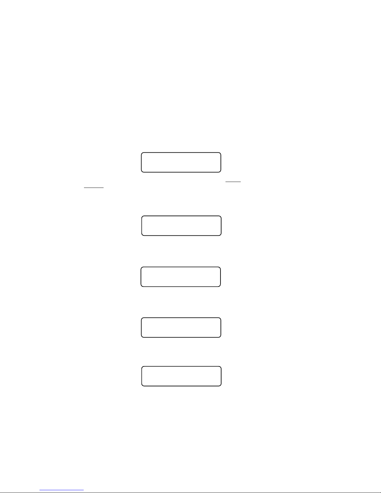
PAGED PROGRAMMING (Option 4)
Option 4 forces the system to use Paged mode while doing Standard and all
subsequent programming. Almost all decoders support Paged Mode.
DIRECT PROGRAMMING (Option 5)
Option 5 forces the system to use Direct mode while doing Standard and all
subsequent programming. Older decoders (built prior to 1/1/2001) do not support
Direct Mode programming.
SETUP NCE LIGHTING EFFECTS (Option 6)
You can use this option to customize the lighting effects for your NCE decoder
equipped locomotives. This programming option will only work with NCE decoders.
NCE EFX 07:04AMNCE EFX 07:04AM
NCE EFX 07:04AM
NCE EFX 07:04AMNCE EFX 07:04AM
OUTPUT NUMBER:OUTPUT NUMBER:
OUTPUT NUMBER:
OUTPUT NUMBER:OUTPUT NUMBER:
Function outputs are numbered from 1 to 14. Do not confuse Output numbers with
Function numbers. The headlight is always output 1 and the reverse light is usually
output 2. You are prompted for the output number to setup. Press the output number
followed by ENTER.
Use the thumbwheel or up/down speed buttons to scroll through the different lighting
effect options. Press ENTER when you get the one you want.
OUTPUT NUMBER:03OUTPUT NUMBER:03
OUTPUT NUMBER:03
OUTPUT NUMBER:03OUTPUT NUMBER:03
USE THUMBWHEEL USE THUMBWHEEL
USE THUMBWHEEL
USE THUMBWHEEL USE THUMBWHEEL
Next press 1,2 or 3 to select the ‘directionality’ of the output. If you want the output
active only in the forward direction of travel - press 1. Press 2 for the effect to
operate only when travelling in reverse. 3 activates the output no matter which
direction the locomotive is travelling.
DIR OF OPERATIONDIR OF OPERATION
DIR OF OPERATION
DIR OF OPERATIONDIR OF OPERATION
1=FW 2=RV 3=BOTH1=FW 2=RV 3=BOTH
1=FW 2=RV 3=BOTH
1=FW 2=RV 3=BOTH1=FW 2=RV 3=BOTH
Last, press 1 if the output has a regular incandescent bulb attached. Press 2 if the
output has an LED connected. LEDs behave differently when dimmed than
incandescent bulbs. Pressing 1 or 2 informs the decoder which set of lighting
characteristics to use for this output.
REGULAR BULB ORREGULAR BULB OR
REGULAR BULB OR
REGULAR BULB ORREGULAR BULB OR
LED 1=BULB 2=LEDLED 1=BULB 2=LED
LED 1=BULB 2=LED
LED 1=BULB 2=LEDLED 1=BULB 2=LED
RECOVERY PROGRAMMING (Option 7)
This programming section is included to allow the user to set all registers of the
Decoder to the values that were programmed into it at the factory.
RECOVERYRECOVERY
RECOVERY
RECOVERYRECOVERY
PROGRAM 1=YESPROGRAM 1=YES
PROGRAM 1=YES
PROGRAM 1=YESPROGRAM 1=YES
Press 1 to enter Recovery mode. This will reprogram NCE decoders (and most
others) to their original factory values. It will also set addresses, motor control CVs
and Function Mapping CVs to a useful state so that you can get control of a decoder.
As each CV is programmed the CV number is displayed.
56
Page 57

DECODER UNLOCK (Option 8)
This programming section is included to allow the user to unlock a decoder that has
been locked (CV 15, 16) and you do not remember the locking value.
PROG TRK 0:00PROG TRK 0:00
PROG TRK 0:00
PROG TRK 0:00PROG TRK 0:00
UNLOCK? 1=YESUNLOCK? 1=YES
UNLOCK? 1=YES
UNLOCK? 1=YESUNLOCK? 1=YES
Press 1 to automatically unlock the decoder. The display will cycle through all
possible values of CV 15. This may take up to 5 minutes.
PROG TRK 0:00PROG TRK 0:00
PROG TRK 0:00
PROG TRK 0:00PROG TRK 0:00
TESTING CV15=XXTESTING CV15=XX
TESTING CV15=XX
TESTING CV15=XXTESTING CV15=XX
SETUP COMMAND STATION
(Shortcut = PROG 5)
This allows the operator to view the Power Cab’s version number and set various
system (not decoder) parameters.
DISPLAY SOFTWARE VERSION AND DATE
This screen is important when the time comes to call or write about a question or a
problem.
NCE 01:30AMNCE 01:30AM
NCE 01:30AM
NCE 01:30AMNCE 01:30AM
POWER CAB V1.28POWER CAB V1.28
POWER CAB V1.28
POWER CAB V1.28POWER CAB V1.28
The following screens are available should a need arise to change any of the factory
settings. There is probably no reason to ever change these settings. If you get things
REALLY messed up you can reset the system to original factory settings (see
paragraph above).
NUMBER OF STOP PACKETS (default is 8)
This adjusts how many times a stop command is sent to the Loco. If you have a
large layout or run more than about 40 different locomotives in a session we
recommend setting this to 8. This will automatically purge non-necessary speed 0
commands from being sent to the track increasing system response to throttle
commands.
NUMBER 02:00PMNUMBER 02:00PM
NUMBER 02:00PM
NUMBER 02:00PMNUMBER 02:00PM
OF STOP PKTS 008OF STOP PKTS 008
OF STOP PKTS 008
OF STOP PKTS 008OF STOP PKTS 008
If set to zero all speed 0 commands will continue to be circulated for every
locomotive that has been controlled (but now is stopped) since the system was last
turned on. Factory default is 8. Press ENTER to skip setting this parameter.
NUMBER OF TEMP PACKETS (default is 4)
This adjusts the number of Function control commands that are sent when a
Function control button is pressed. Factory default is 5. Press ENTER to skip setting
this parameter.
NUMBER 02:00PMNUMBER 02:00PM
NUMBER 02:00PM
NUMBER 02:00PMNUMBER 02:00PM
OF TEMP PKTS 004OF TEMP PKTS 004
OF TEMP PKTS 004
OF TEMP PKTS 004OF TEMP PKTS 004
57
Page 58
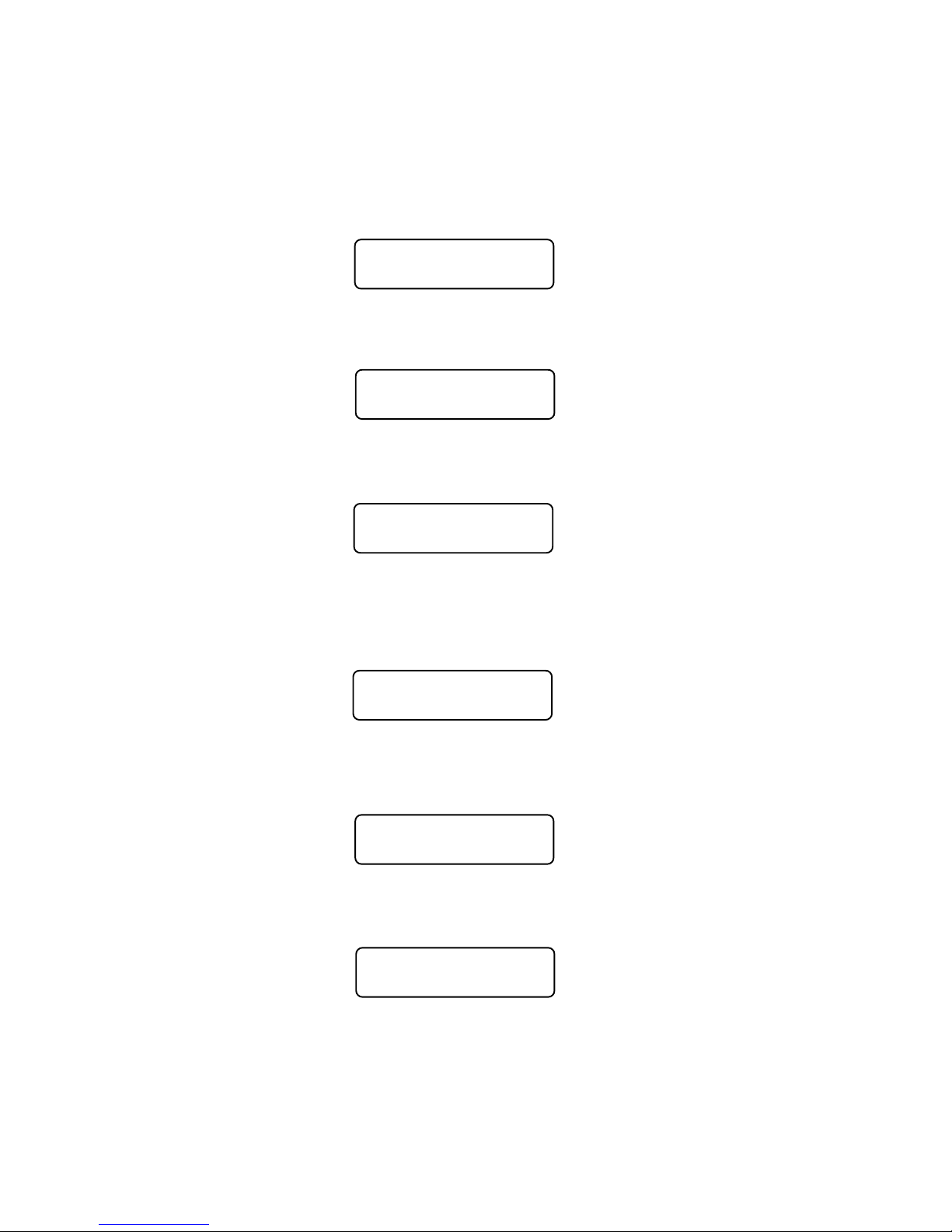
NUMBER OF ACCESSORY PACKETS (default is 4)
This adjusts the number of accessory control commands sent when an accessory
or signal is controlled. Factory default is 4. Press ENTER to skip setting this
parameter.
NUMBER 02:00PMNUMBER 02:00PM
NUMBER 02:00PM
NUMBER 02:00PMNUMBER 02:00PM
OF ACC PKTS: 004OF ACC PKTS: 004
OF ACC PKTS: 004
OF ACC PKTS: 004OF ACC PKTS: 004
NUMBER OF HORN OFF PACKETS (default is 2)
This adjusts the number of times a “horn off” packet is sent when the HORN button
is released. The factory default is 2 but can be set as high as 16. Press ENTER to
skip setting this parameter.
NUMBER 02:00PMNUMBER 02:00PM
NUMBER 02:00PM
NUMBER 02:00PMNUMBER 02:00PM
HORN OFF PKT 002HORN OFF PKT 002
HORN OFF PKT 002
HORN OFF PKT 002HORN OFF PKT 002
NUMBER OF PROGRAM PACKETS (default is 4)
This adjusts the number of times a programming command is sent when
programming a locomotive on the mainline. Factory default is 4. Press ENTER to
skip setting this parameter.
NUMBER 02:00PMNUMBER 02:00PM
NUMBER 02:00PM
NUMBER 02:00PMNUMBER 02:00PM
OF PROG PKTS 004OF PROG PKTS 004
OF PROG PKTS 004
OF PROG PKTS 004OF PROG PKTS 004
SEND FUNCTION COMMANDS TO CONSIST ADDRESS
(default is 1=Y)
Function commands are normally sent to the lead loco of an advanced consist. They
can also be sent to the consist address so that other locomotives in consist can
react to these commands if desired. The factory default is yes. Press ENTER to skip
setting this parameter.
SEND FUNCTION TOSEND FUNCTION TO
SEND FUNCTION TO
SEND FUNCTION TOSEND FUNCTION TO
CON? 1=Y 0=N 1CON? 1=Y 0=N 1
CON? 1=Y 0=N 1
CON? 1=Y 0=N 1CON? 1=Y 0=N 1
CONSIST MOMENTUM (default is 1=Y)
You can disable the momentum button on all handheld cabs that are operating a
consist. The buttons are enabled by factory default. Press ENTER to skip setting this
parameter.
CONSIST MOMENTUMCONSIST MOMENTUM
CONSIST MOMENTUM
CONSIST MOMENTUMCONSIST MOMENTUM
ENABLE 1=Y 0=N 1ENABLE 1=Y 0=N 1
ENABLE 1=Y 0=N 1
ENABLE 1=Y 0=N 1ENABLE 1=Y 0=N 1
MOMENTUM MULTIPLIER (default is 8)
When you press the MOMENTUM button you are prompted for a single digit
indicating how much momentum you want for the loco/consist you are controlling.
Momentum CVs have a range of 0-255 while the button asks for values from 0-9.
MOMENTUM BUTTONMOMENTUM BUTTON
MOMENTUM BUTTON
MOMENTUM BUTTONMOMENTUM BUTTON
MULTIPLIER: 08MULTIPLIER: 08
MULTIPLIER: 08
MULTIPLIER: 08MULTIPLIER: 08
The value you enter for the momentum button is multiplied by this parameter (factory
default of 8) and sent to CV3 in the locomotive. This parameter adjusts the
58
Page 59
multiplication factor. You can set it from 0-25. Press ENTER to skip setting this
parameter.
MOMENTUM DECELERATION RATE (default is 0=HALF)
The deceleration rate (CV4) when pressing the momentum button can be either half
the value sent for acceleration (CV3) or the full value sent to CV3. Factory default is
½. Press ENTER to skip setting this parameter.
MOMEN DECEL RATEMOMEN DECEL RATE
MOMEN DECEL RATE
MOMEN DECEL RATEMOMEN DECEL RATE
1=FULL 0=HALF 01=FULL 0=HALF 0
1=FULL 0=HALF 0
1=FULL 0=HALF 01=FULL 0=HALF 0
FUNCTION REFRESH (default is 0=OFF)
Function Refresh will keep the lights and sounds working (F0 through F8) on
locomotives that don’t remember the state of their functions on start up and dirty
track. The Function Refresh rate is set to occur about once per second. If all
functions are OFF or the locomotive speed is Zero (0), the functions for that
locomotive will not be refreshed.
FUNCTION REFRESHFUNCTION REFRESH
FUNCTION REFRESH
FUNCTION REFRESHFUNCTION REFRESH
ENABLE 1=Y 0=NENABLE 1=Y 0=N
ENABLE 1=Y 0=N
ENABLE 1=Y 0=NENABLE 1=Y 0=N
RESET SYSTEM?
Reset System will reset all of the system configuration settings to their factory
defaults. Only the Power Cab memory will be reset, the memory as a Pro Cab will
remain.
RESET SYSTEM?RESET SYSTEM?
RESET SYSTEM?
RESET SYSTEM?RESET SYSTEM?
PRESS 6 FOR YESPRESS 6 FOR YES
PRESS 6 FOR YES
PRESS 6 FOR YESPRESS 6 FOR YES
Press 6 to enter the Reset action.
ARE YOU SURE?ARE YOU SURE?
ARE YOU SURE?
ARE YOU SURE?ARE YOU SURE?
PRESS 1 FOR YESPRESS 1 FOR YES
PRESS 1 FOR YES
PRESS 1 FOR YESPRESS 1 FOR YES
The system will reset itself and take you back to the opening screen.
SET UP THE CAB PARAMETERS
(Shortcut = PROG 6)
SHOW TRACK CURRENT:
SHOW 02:00PMSHOW 02:00PM
SHOW 02:00PM
SHOW 02:00PMSHOW 02:00PM
TRK CURRENT? 1=YTRK CURRENT? 1=Y
TRK CURRENT? 1=Y
TRK CURRENT? 1=YTRK CURRENT? 1=Y
Press 1 to enable the display of current being supplied to the main running track by
the system when in normal operations mode. Current display will be cancelled by
programming on the main, using the program track, or cycling the system power.
59
Page 60
NUMBER OF RECALLS
This adjusts the number of recall “slots” that are cycled through when the RECALL
key is pressed. Enter a number of Recalls from 1 - 6 and press ENTER. This can be
set differently for each Cab. (factory default is 2) Press ENTER to skip setting this
parameter.
NUMBER 02:00PMNUMBER 02:00PM
NUMBER 02:00PM
NUMBER 02:00PMNUMBER 02:00PM
OF RECALLS: 02OF RECALLS: 02
OF RECALLS: 02
OF RECALLS: 02OF RECALLS: 02
ANALOG HORN CHANNEL (default is 0)
ANALOG 02:00PMANALOG 02:00PM
ANALOG 02:00PM
ANALOG 02:00PMANALOG 02:00PM
HORN CHANNEL _HORN CHANNEL _
HORN CHANNEL _
HORN CHANNEL _HORN CHANNEL _
If you have a decoder that supports a “playable” whistle such as a SoundTraxx
Tsunami, enter the analog “channel number” that the decoder uses for whistle. You
can play the whistle by holding the HORN/WHISTLE button while moving the
thunbwheel. If the channel is set to 0 no analog commands will be sent.
ANALOG AUX CHANNEL (default is 0)
ANALOG 02:00PMANALOG 02:00PM
ANALOG 02:00PM
ANALOG 02:00PMANALOG 02:00PM
AUX CHANNEL: _AUX CHANNEL: _
AUX CHANNEL: _
AUX CHANNEL: _AUX CHANNEL: _
ANALOG BIAS (default is 0)
ANALOG 02:00PMANALOG 02:00PM
ANALOG 02:00PM
ANALOG 02:00PMANALOG 02:00PM
BIAS (0-15) BIAS (0-15)
BIAS (0-15)
BIAS (0-15) BIAS (0-15)
This is the starting point or “level” (0-15) at which analog commands will start.
_ _
_
_ _
ASSIGNING THE BELL FUNCTION (default is 1)
Enter the function number that should be activated when the Bell key is pressed. We
recommend using 1, however any function number may be used. Soundtraxx Diesel
decoders use Function #1 for control of the Bell.
ASSIGN 02:00PMASSIGN 02:00PM
ASSIGN 02:00PM
ASSIGN 02:00PMASSIGN 02:00PM
BELL TO FUNC: 1BELL TO FUNC: 1
BELL TO FUNC: 1
BELL TO FUNC: 1BELL TO FUNC: 1
Older Soundtraxx Steam decoders use Function #3 for the Bell. The steam
decoders can have the bell “re-mapped” to Function #1 (Diesel decoders can not remap the bell to Function #3). Press ENTER to skip setting this parameter.
60
Page 61
PROGRAM ACCESSORY DECODERS
(Shortcut = PROG 7)
This allows the operator to set Accessory Decoder CVs while they are connected to
the Track (Accessory Programming on the Main).
ENTER THE ACCESSORY ADDRESS
Enter the Accessory Decoder address and press ENTER.
PROG ACC 02:00PMPROG ACC 02:00PM
PROG ACC 02:00PM
PROG ACC 02:00PMPROG ACC 02:00PM
ACC. ADDR: _ACC. ADDR: _
ACC. ADDR: _
ACC. ADDR: _ACC. ADDR: _
ENTER THE CV NUMBER
Enter the CV number that you want to program and press ENTER.
PROG ACC 02:00PMPROG ACC 02:00PM
PROG ACC 02:00PM
PROG ACC 02:00PMPROG ACC 02:00PM
ENTER CV NUM:_ENTER CV NUM:_
ENTER CV NUM:_
ENTER CV NUM:_ENTER CV NUM:_
ENTER THE CV VALUE
Enter the value you want in the CV and press ENTER.
PROG ACC 02:00PMPROG ACC 02:00PM
PROG ACC 02:00PM
PROG ACC 02:00PMPROG ACC 02:00PM
ENTER VALUE: _ENTER VALUE: _
ENTER VALUE: _
ENTER VALUE: _ENTER VALUE: _
For Compatibility, both “legacy” and new style programming commands are issued to
Accessory Decoders.
PROGRAM MACROS
(Shortcut = PROG 8)
This allows the operator to program Macros (switch lists).
SELECT MACRO PROGRAM OR REVIEW
Press 1 to program a Macro or press 2 to review a programmed Macro.
MACRO: 02:00PMMACRO: 02:00PM
MACRO: 02:00PM
MACRO: 02:00PMMACRO: 02:00PM
1=PROG 2=REVIEW1=PROG 2=REVIEW
1=PROG 2=REVIEW
1=PROG 2=REVIEW1=PROG 2=REVIEW
If 1 is pressed the following screen is displayed.
MACRO: 02:00PMMACRO: 02:00PM
MACRO: 02:00PM
MACRO: 02:00PMMACRO: 02:00PM
MACRO NUMBER:_MACRO NUMBER:_
MACRO NUMBER:_
MACRO NUMBER:_MACRO NUMBER:_
ENTER THE MACRO NUMBER
Enter the Macro number that you want to program (0-15), and press ENTER.
61
Page 62
ENTER THE ACCESSORY ADDRESS
LINKING MACROS
Enter the Accessory Address that you want to control, and press ENTER. A macro
can be linked to another macro by entering an accessory address of 9999 at this
point. You will be prompted for the macro number to link.
MAC: 000 02:00PMMAC: 000 02:00PM
MAC: 000 02:00PM
MAC: 000 02:00PMMAC: 000 02:00PM
ACCESSORY #: _ACCESSORY #: _
ACCESSORY #: _
ACCESSORY #: _ACCESSORY #: _
You can chain as many macros together as you like but use caution. If you chain
macros in a ‘circular’ fashion the system will appear to crash (it is busy sending
macros continuously) until you press PROG/ESC on the cab that issued the macro.
If a computer is used the only solution is to cycle the power to the system and fix the
circular reference.
SELECT THE TURNOUT POSITION
Press 1 for Normal or 2 for Route.
MAC: 000 02:00PMMAC: 000 02:00PM
MAC: 000 02:00PM
MAC: 000 02:00PMMAC: 000 02:00PM
ACC: 001 1=N 2=RACC: 001 1=N 2=R
ACC: 001 1=N 2=R
ACC: 001 1=N 2=RACC: 001 1=N 2=R
The above two screens will repeat up to 8 times to allow you to enter up to 8
accessories. After 8 accessories have been entered the SELECT MACRO
PROGRAM OR REVIEW screen will be displayed. If you want to enter less than 8
accessories, leave the accessory # blank (just press ENTER).
If 2 is pressed on the SELECT MACRO PROGRAM OR REVIEW screen, the
following screen is displayed.
ENTER THE MACRO NUMBER TO BE REVIEWED
Enter the Macro number that you want to review (0-15), and press ENTER.
REVIEW: 02:00PMREVIEW: 02:00PM
REVIEW: 02:00PM
REVIEW: 02:00PMREVIEW: 02:00PM
MACRO NUMBER: _MACRO NUMBER: _
MACRO NUMBER: _
MACRO NUMBER: _MACRO NUMBER: _
REVIEW MACRO
The Accessory number and output will be shown. Press ENTER to see the next
Accessory in the Macro. If there are no more Accessories in the Macro, the following
screen will be displayed.
MAC: 000 02:00PMMAC: 000 02:00PM
MAC: 000 02:00PM
MAC: 000 02:00PMMAC: 000 02:00PM
ACCESSORY: 001=NACCESSORY: 001=N
ACCESSORY: 001=N
ACCESSORY: 001=NACCESSORY: 001=N
REVIEW END OF MACRO
After ENTER is pressed, the SELECT MACRO PROGRAM OR REVIEW screen will
be displayed.
MACRO: 02:00PMMACRO: 02:00PM
MACRO: 02:00PM
MACRO: 02:00PMMACRO: 02:00PM
—END OF MACRO——END OF MACRO—
—END OF MACRO—
—END OF MACRO——END OF MACRO—
62
Page 63
BROWSE CONSISTS (Shortcut = PROG 9)
This option lets you see what advanced consists are currently in the memory of the
system.
Press ENTER at the “BROWSE CONSISTS” prompt. The LCD will display the
highest numbered consist in the system memory. It will look something like:
CON: 127 10:42AMCON: 127 10:42AM
CON: 127 10:42AM
CON: 127 10:42AMCON: 127 10:42AM
LEAD:2190 R:4484LEAD:2190 R:4484
LEAD:2190 R:4484
LEAD:2190 R:4484LEAD:2190 R:4484
Use the speed buttons or thumbwheel to scroll the next higher or lower consist in the
list. When you get to the end of the list it will roll over to the ‘other’ end. Pressing
ENTER will show any mid consist locomotives of the displayed consist.
Pressing ENTER while the Lead/Rear locomotives are displayed will show any midconsist locomotives. (The system will remember up to 2 mid-consist locos per
advanced consist). Press ENTER again to view the next consist.
Pressing SEL LOCO will exit browsing and select the displayed consist for running.
Pressing CLEAR then pressing 1 at the “KILL CON?” prompt will kill the displayed
consist.
Press PROG/ESC at any time to exit browsing.
PROGRAM SIGNAL DECODERS
(Shortcut = PROG 0)
This allows the operator to setup Signal Decoders while they are connected to the
Track (Signal Programming on the Main).
ENTER THE SIGNAL ADDRESS
Enter the Decoder address and press ENTER.
PROG ACC 02:00PMPROG ACC 02:00PM
PROG ACC 02:00PM
PROG ACC 02:00PMPROG ACC 02:00PM
SIGNAL NUM: _SIGNAL NUM: _
SIGNAL NUM: _
SIGNAL NUM: _SIGNAL NUM: _
ENTER THE CV NUMBER
Enter the CV number that you want to program and press ENTER.
PROG ACC 02:00PMPROG ACC 02:00PM
PROG ACC 02:00PM
PROG ACC 02:00PMPROG ACC 02:00PM
ENTER CV NUM: _ENTER CV NUM: _
ENTER CV NUM: _
ENTER CV NUM: _ENTER CV NUM: _
ENTER THE CV VALUE
Enter the value you want in the CV and press ENTER.
PROG ACC 02:00PMPROG ACC 02:00PM
PROG ACC 02:00PM
PROG ACC 02:00PMPROG ACC 02:00PM
ENTER VALUE: _ENTER VALUE: _
ENTER VALUE: _
ENTER VALUE: _ENTER VALUE: _
63
Page 64

HELPFUL HINTS FOR OPERATION
l Passing an old style consist: Use ASSIGN LOCO TO CAB to transfer an old
style consist to any other Cab on the system. This causes a swap between the
active loco/consist on your Cab and the active loco/consist on the target Cab.
l Nesting consists: Say a heavy freight is approaching a long grade and helpers
are needed. The train’s locomotives are an advanced consist. The two GP9
pushers are also consisted using an advanced consist. The pusher consist is
brought out of the siding at the base of the grade and put in place. An “old style”
consist is now set up using the freight’s lead loco number and the pusher’s lead
loco number. You can now operate the entire train to the grade crest as one unit.
Upon reaching the cutoff siding at the crest, the “old style” consist is killed and the
pushers are selected to move to the siding. The freight consist continues on while
the pushers drift back down the hill.
l When setting up an old style Consist, you may want to use a Loco number that
does not exist for the first Loco (Consist address). This will allow you to put the
actual lead loco in recall to operate the headlight, and the sound loco to operate the
Horn and Bell.
l· If a cab does not respond after plugging it in, press the ENTER key a couple of
times. This will cause it to exit from any mode it was in when it was unplugged.
l When making your own cables using RJ plugs be SURE the connectors are
“flipped” over at opposite ends of the wire. See the illustration on page 21 for
proper cab bus cabling.
Using the Power Cab/ProCab
l In DCC there are 2 kinds of addresses (loco numbers), long and short. When
entering the address of the loco you wish to control long addresses from 1 to 127
are entered by preceding the actual number by a zero. Short addresses are
entered without a leading zero. Long addresses in the range of 1 -127 are
displayed on your cab with an asterisk before the loco number. ie: “*042” indicates
the long address for loco forty-two and “042” indicates the short address. Most
modern decoders made since 1997 support long (4 digit) addresses. Older Lenz,
Digitrax and MRC decoders only support the short address.
l When entering numbers if you make a mistake there is no “erase” or “backup”
key. If you keep pressing digits the display will clear allowing you to start entering
your number over again.
l If you wish to abandon what you are doing when in the middle of entering a
number push the “PROG/ESC” key and you will be returned to normal operation.
l During various operations where you are doing something other than normal
loco operation such as “set up consist” or “select accessory” speed control of the
loco is not available, however the Emergency Stop will still work if you need to stop
your loco.
l Programming on the programming track the command station first reads the
value of a location (such as “short address” or “acceleration”) and displays it on
your cab. If you wish to accept this value just press ENTER to continue or type in
a new number if you want to change it.
Programming Track
l The command station checks for a short circuit on the programming track
before applying power. If your loco has lights or other current drawing devices
wired directly to the track instead of a decoder function output the command
station will probably think is has a short and will say “SHORT DETECTED” each
time you start to program this loco. If you wish you will be allowed to override the
short and continue. This short detection is there to protect decoders from damage
if they are miswired. For this reason we always try a new decoder installation on
the programming track first instead of putting it directly on the layout. If the
programming works the installation is most likely correct.
64
Page 65

TROUBLE SHOOTING
l Locomotive was running yesterday but today it just sits there - The headlight and
other functions are controllable but it won’t run. - This sometimes happens when you
clear a consist but for some reason the decoder misses the command. Use the DEL
LOCO button to “re-delete” the locomotive. Alternatively use programming on the
main to set CV19 to 0 (same thing as clearing the consist).
l Head Light goes on and off as I change speed - You are operating a loco with an
older 14 step decoder in the 28 step mode and the head light is ON only in the even
speed steps.
l The programmability of the decoders gives the modeler a lot of flexibility. However,
this can lead to some unpredictable results. Here are a few tips to get you out of
some situations:
l Loco won’t respond -
l Check that the short/long address bit is set correctly in the CFG variable (CV 29).
l The loco might be in a consist - Press DEL LOCO, the locomotive number
then ENTER.
l Make sure CV3, 4, 23, 24 are set to a small enough value to allow the loco to
accelerate at a reasonable rate
l Loco won’t run on an analog (DC) layout - Check that the DC mode bit is set in
the CFG variable (CV 29).
65
Page 66

Copyright & Trademarks
Copyright © 1994-2010 NCE Corporation. The identifying product terms Power
CabTM, PH-ProTM, ProCabTM, and SmartCabTM are trademarks of NCE Corporation. The
look and feel of this software and its interaction with the user through the ProCab or
SmartCab is copyright NCE Corporation. The distinctive shape of the ProCabTM with
LCD and/or thumbwheel is a trademark of NCE Corporation. Digitrax® is a registered
trademark of Digitrax® Inc. All other non-NCE brands and product names mentioned
are likely to be trademarks or registered trademarks of their respected companies.
Limited Warranty
NCE guarantees that every Power CabTM DCC System is free from physical defects
in material and workmanship for a period of 1 year.
Within the first year full repair or replacement will be made to the original purchaser of
any item that has failed due to manufacturer defect. Should the item no longer be
produced and the item not repairable a similar item will be substituted at the
manufacturer’s discretion. The customer pays only shipping to the NCE Warranty
Center. Please save your original receipt as a photocopy of it may be requested.
NCE returns the items UPS ground unless other arrangements are made in
advance.
After the first year a fair and reasonable service charge may be placed on each
failed item returned for repair. Should the item no longer be produced and the item not
repairable a similar item will be substituted at the manufacturer’s discretion. The
customer pays shipping to and from the NCE Warranty Center.
This warranty is not valid if the customer has intentionally misused, miswired,
performed any unauthorized alterations to the product or removed any product
protection devices (such as heat shrink wrapping from decoders). In this case a
service charge will be applied for all repairs and replacements. To protect the
warranty, please contact the Warranty Center for authorization prior to altering any
product. In no event will NCE’s liability exceed the price paid for the product from
direct, indirect, special, incidental or consequential damages resulting from the use of
the product, it’s accompanying software or its documentation. NCE makes no
warranty or representation, expressed, implied or statutory with respect to its
products or the contents or use of this documentation and accompanying software
and specifically disclaims its quality, performance, merchantability, or fitness for any
particular purpose. NCE reserves the right to revise or update its products, software,
or documentation without obligation to notify any individual or entity.
Please contact the Warranty Center for specific shipping instructions and any
service charges before returning any product for service. Address all inquiries to:
66
NCE Warranty Center
82 East Main St.
Webster, New York 14580
Phone: 585-265-0230 Fax: 585-265-0234
Page 67

FCC Statement
This NCE product complies with the limits for a Class B digital device, pursuant to
Part 15 of the FCC rules. These limits are designed to provide reasonable protection
against harmful interference in a residential installation. This equipment generates,
uses and can radiate radio frequency energy and, if not installed and used according
to the instructions, may cause harmful interference to radio communications.
However, there is no guarantee that interference will not occur in a particular
installation. Keep in mind that by FCC rules, all electronic equipment must accept
any interference, including interference that may cause undesired operation. If this
equipment does cause harmful interference to radio, or television reception, which is
found by turning the equipment off and on, the user is encouraged to correct the
interference by one or more of the following measures:
l Reorient or relocate the receiving antenna
l Increase the separation between the equipment and the device
l Connect the equipment to an outlet other than the receiver’s
l Consult a dealer or an experienced radio/TV technician for assistance
About NCE
NCE has been manufacturing DCC Products on an OEM basis since 1993. Originally
we offered only “chip sets” that contained software enabling other DCC
manufacturers to build DCC systems. As time went on some of those manufacturers
asked us to first supply partial assemblies then complete assemblies in addition to
the chip sets. This has helped NCE to grow into a full time electronic design and
manufacturing firm devoted entirely to the development and sale of products for the
control of model railroads. We build an amazing array of products for both our own
customers and other DCC manufacturers. We keep labor costs low by utilizing
modern automated robotic assembly for most products.
Our product designer is Jim Scorse. Jim models the Erie Railroad in O-Scale and
has a long history in model railroading. He has numerous patents in the area of digital
imaging, video and computer network data communications over noisy channels. Jim
is active in the Layout Design SIG as well as 30 years with the “Tuesday Night
Gang”, (round robin model railroad club) and is probably one of the only active model
railroaders among all the DCC manufacturers.
67
Page 68
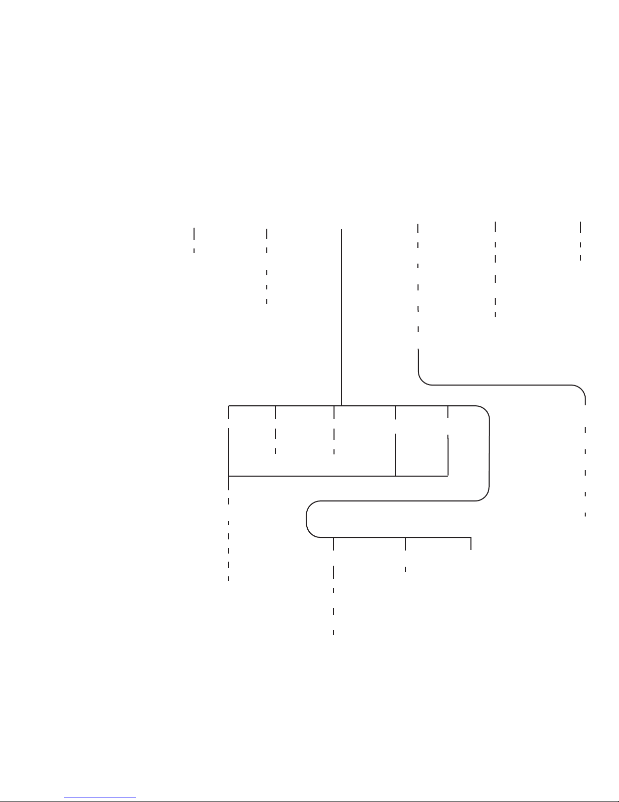
MENU NAVIGATION CHART - Part 2
3 Register
Enter Register #
Enter Value
4 Paged
Programming
5 Direct
Programming
7 Recovery
Program
Factory
Reprogram?
6 NCE
Effects
Output #
Choose
effect
Direction
of Operation
Bulb or LED
2
ASSIGN
LOCO TO
CAB
Loco #
Cab #
3
SET
SYSTEM
CLOCK
Start/Stop
12/24
Hour
Hours
Minutes
Ratio
4
USE
PROGRAM
TRK
5
SET CMD
STATION
Version
# of Stop
Packets
# of Temp
Packets
# of Acc
Packets
# of Horn
off PKT
# of Prog
Packets
7
PROG ACCY
ON MAIN
Accy Address
Enter CV#
Enter Value
2 CV
Enter CV #
Enter Value
8 Decoder
Unlock
1 Standard
Manufacturer
Decoder
Version
Set Up Address
Set Config
Motor Control
Function Map
Set CV
Send Function
to Consist?
Consist Momentum
Enable
Momentum
button Multiplier
Momentum
Decel Rate
Function Refresh
Enable
Reset System?
6
SET CAB
PARAMS
Track Current
Recalls
Analog Horn
Channel
Analog Aux
Channel
Analog Bias
Assign Bell
to Function
Press PROG/ESC Key to cycle through menu listings, then press ENTER to cycle through listing choices
68
Page 69
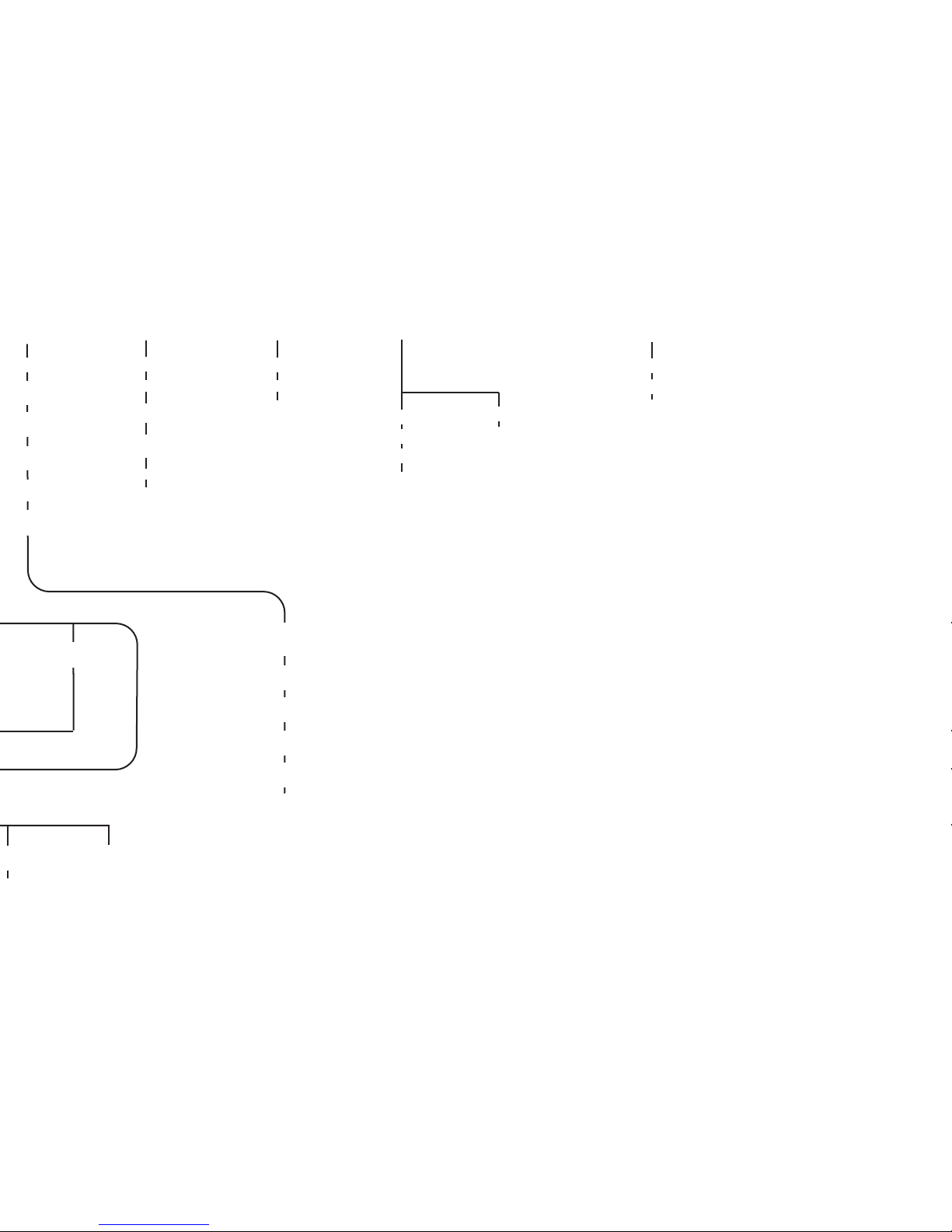
5 Direct
Programming
5
SET CMD
STATION
Version
# of Stop
Packets
# of Temp
Packets
# of Acc
Packets
# of Horn
off PKT
# of Prog
Packets
9
BROWSE
CONSISTS
7
PROG ACCY
ON MAIN
Accy Address
Enter CV#
Enter Value
0
PROG SIG
ON MAIN
Enter Signal #
Enter CV
Enter Value
8
PROGRAM
MACROS
Program
Enter Macro #
Enter Accy #
Enter N or R
Review
Enter Macro #
8 Decoder
Unlock
Send Function
to Consist?
Consist Momentum
Enable
Momentum
button Multiplier
Momentum
Decel Rate
Function Refresh
Enable
Reset System?
6
SET CAB
PARAMS
Track Current
Recalls
Analog Horn
Channel
Analog Aux
Channel
Analog Bias
Assign Bell
to Function
69
Page 70
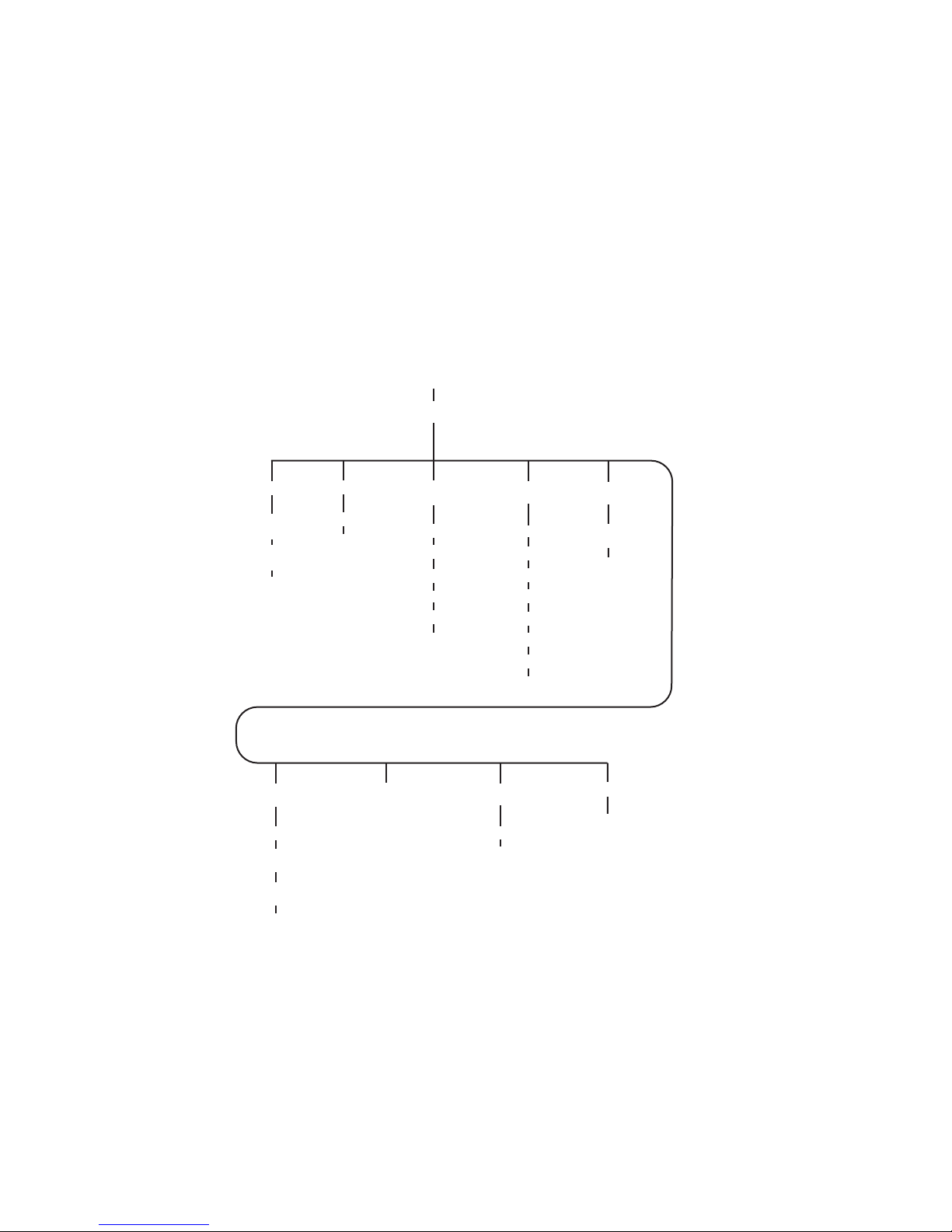
Press PROG/ESC key to cycle through menu listings, then press ENTER to
9 BIN CV
Factory
Reprogram?
1
PROGRAM
ON MAIN
Prog Loco:
1 Address
Long or
Short
Enter
Address
Run Loco
2 CV
Enter CV #
Enter Value
3 CFG
(CV29)
Direction Bit
Speed Steps
DC Mode?
Adv Acknowledge?
SpeedTable
Address
4 Motor
Control
Start Volts
Max Volts
Mid Volts
Accel
Decel
PWM Freq
Kick Rate
Kick Depth
5 Function
Map
Function #
to Map
F# =
Outputs
7 Not Used
8 QSI
Sound
Enter CV #
Enter Value
6 NCE
Effects
Output #
Choose
effect
Direction
of Operation
Bulb or LED
MENU NAVIGATION CHART - PT.1
cycle through listing choices.
70
Page 71
NCE Corporation
82 East Main St.
Webster, NY 14580
(585) 265-0230
ncedcc.com
0524030105240301
05240301
0524030105240301
05240301
71
 Loading...