

Page 1
PB5
5 Amp Booster
Reference Manual
NCE Corporation
82 East Main Street
Webster, NY 14580
Page 2

PRODUCT MANUAL FOR PB5
5 AMP BOOSTER
PREFACE
This manual provides information pertaining to the
installation and operation of the PB5 BOOSTER only.
COMPONENTS
The PB5 comes supplied as follows:
1 - Black box labeled Five Amp Power Booster in the upper
center and PB5 in the lower, right corner.
1 - 7 foot cable with modular telephone plugs on both ends.
Each plug has four gold-plated contacts. This is the
control bus cable. For the technically inclined, this is a 4-
wire cable with RJ-H connectors.
1 - Track Connector Plug
1 - DC Power Supply with additional 25%, 30 sec. Surge
capability.
1 - PB5 Manual.
Page 1
particular purpose. NCE reserves the right to revise or update its products, software,or
documentation without obligation to notify any individual or entity.
Please contact the Warranty Center for specific shipping instructions and any
service charges before returning any product for service. Address all inquiries to:
NCE Warranty Center
82 East Main Street
Webster, New York 14580
Phone: 585-265-0230 Fax: 585-265-0234
FCC Statement
This NCE product complies with the limits for a Class B digital device, pursuant to
Part 15 of the FCC rules. These limits are designed to provide reasonable protection
against harmful interference in a residential installation. This equipment generates,
uses and can radiate radio frequency energy and, if not installed and used according
to the instructions, may cause harmful interference to radio communications.
However, there is no guarantee that interference will not occur in a particular
installation. Keep in mind that by FCC rules, all electronic equipment must accept
any interference, including interference that may cause undesired operation. If this
equipment does cause harmful interference to radio, or television reception, which is
found by turning the equipment off and on, the user is encouraged to correct the
interference by one or more of the following measures:
Reorient or relocate the receiving antenna
Increase the separation between the equipment and the device
Connect the equipment to an outlet other than the receiver’s
Consult a dealer or an experienced radio/TV technician for assistance
About NCE
NCE has been manufacturing DCC Products on an OEM basis since 1993. Originally
we offered only “chip sets” that contained software enabling other DCC
manufacturers to build DCC systems. As time went on some of those manufacturers
asked us to first supply partial assemblies then complete assemblies in addition to
the chip sets. This has helped NCE to grow into a full time electronic design and
manufacturing firm devoted entirely to the development and sale of products for the
control of model railroads. We build an amazing array of products for both our own
customers and other DCC manufacturers. We keep labor costs low by utilizing
modern automated robotic assembly for most products.
Our product designer is Jim Scorse. Jim models the Erie Railroad in O-Scale and
has a long history in model railroading. He has numerous patents in the area of digital
imaging, video and computer network data communications over noisy channels. Jim
is active in the Layout Design SIG as well as 30 years with the “Tuesday Night
Gang”, (round robin model railroad club) and is probably one of the only active model
railroaders among all the DCC manufacturers.
Page 6
Page 3
WIRING TO A DIGITRAX SYSTEM
This wiring diagram is provided for the operators that wish to
add an NCE power booster to their existing DIGITRAX
system. This cable splicing is required to the first
DB100/DB150 only. Always leave the “Ground to Sync”
Jumper installed.
Copyright & Trademarks
Copyright © 2012 NCE Corporation. The identifying product terms Power
CabTM, PH-ProTM, ProCabTM, and SmartCab
TM
are trademarks of NCE Corporation. The
look and feel of this software and its interaction with the user through the ProCab or
Power Cab is copyright NCE Corporation. The distinctive shape of the ProCab
TM
with
LCD and/or thumbwheel is a trademark of NCE Corporation. Digitrax® is a registered
trademark of Digitrax® Inc. All other non-NCE brands and product names mentioned
are likely to be trademarks or registered trademarks of their respected companies.
Limited Warranty
NCE guarantees that every NCE DCC System is free from physical defects
in material and workmanship for a period of 1 year. Within the first year full repair or
replacement will be made to the original purchaser of any item that has failed due to
manufacturer defect. Should the item no longer be produced and the item not repairable a
similar item will be substituted at the manufacturer’s discretion. The customer pays only
shipping to the NCE Warranty Center. Please save your original receipt as a photocopy of
it may be requested. NCE returns the items UPS ground unless other arrangements are
made in advance. After the first year a fair and reasonable service charge may be placed
on each failed item returned for repair. Should the item no longer be produced and the item
not repairable a similar item will be substituted at the manufacturer’s discretion. The
customer pays shipping to and from the NCE Warranty Center. This warranty is not valid if
the customer has intentionally misused, miswired, performed any unauthorized alterations
to the product or removed any product protection devices (such as heat shrink wrapping
from decoders). In this case a service charge will be applied for all repairs and
replacements. To protect the warranty, please contact the Warranty Center for
authorization prior to altering any product. In no event will NCE’s liability exceed the price
paid for the product from direct, indirect, special, incidental or consequential damages
resulting from the use of the product, it’s accompanying software or its documentation.
NCE makes no warranty or representation, expressed, implied or statutory with respect to
its products or the contents or use of this documentation and accompanying software
and specifically disclaims its quality, performance, merchantability, or fitness for any
Page 5
Red
Green
Cut off black wire
Cut off yellow wire
Supplied4 position
RJ-Hcable
NCE boostercoverscrew
ConnectTerminal"E" to
Connection from Lenz command station to NCE booster
Connectorto
LenzCommandStattion
for ground
ConnecttoNCEbooster
"ControlBus"jack
C
D
E
CONNECTIONS, CONTROLS and INDICATORS
Starting at the left side of the front panel, each terminal,
socket, switch and indicator is explained below:
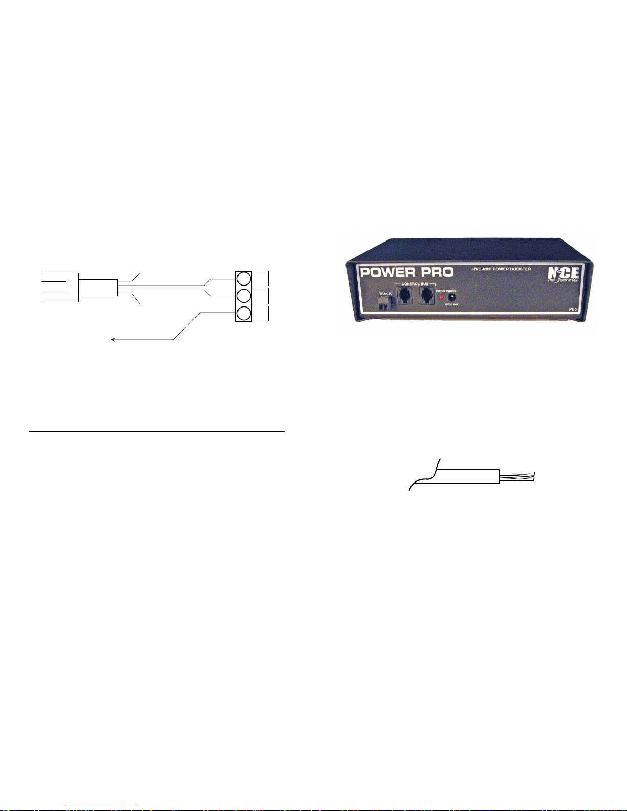
TRACK TERMINALS:
The screw terminals of the black connector are designed to
accept wires up to #14 AWG (2mm). Insulation should be
stripped back 1/4 inch (6mm). Only stranded wire should be
used. Do not tin the wires to prevent fraying. If solid wire is
used for track power, make a splice joint to stranded wire at
some convenient place. Only stranded wire should enter the
terminal for reliable contact.
Wires from these terminals go to the track. If more than one
booster is connected to the layout, be sure the left track
terminal on all boosters is consistently wired to the same rail.
This will ensure you have the same “phase” as you cross
power district boundaries. Always use wire of sufficient
gauge (#18 minimum) to connect to the layout. Power
“drops” of #24 or #22 wire to a larger wire bus under the
track are fine as long as the length of each drop to the main
Page 2
Insulation
BareWire
Page 4
bus is less than 2 feet. Use of a smaller bus will prevent the
booster from detecting a short circuit and may be a fire
hazard.
The voltage to the track is dependent on the power source
input voltage as discussed below. The DCC track voltage
can be changed from 13.8 to 12 Volts by setting the switch
on the power supply for N, HO and some S Scales. We offer
a 9 Volt power source for Z Scale. Please call us at 585-2650230 for a replacement. We do not recommend using a 5
Amp booster with O-Scale as most O-Scale locomotives
have stall currents in the area of 8 Amps (Weaver, Red
Caboose, P&D). For O-Scale usage we recommend our
PB110 ten Amp power booster.
CONTROL BUS SOCKETS
The control bus sockets on the front of the PB5 are paired to
allow wiring the control signal coming from the command
station to “daisy chain” through the booster.
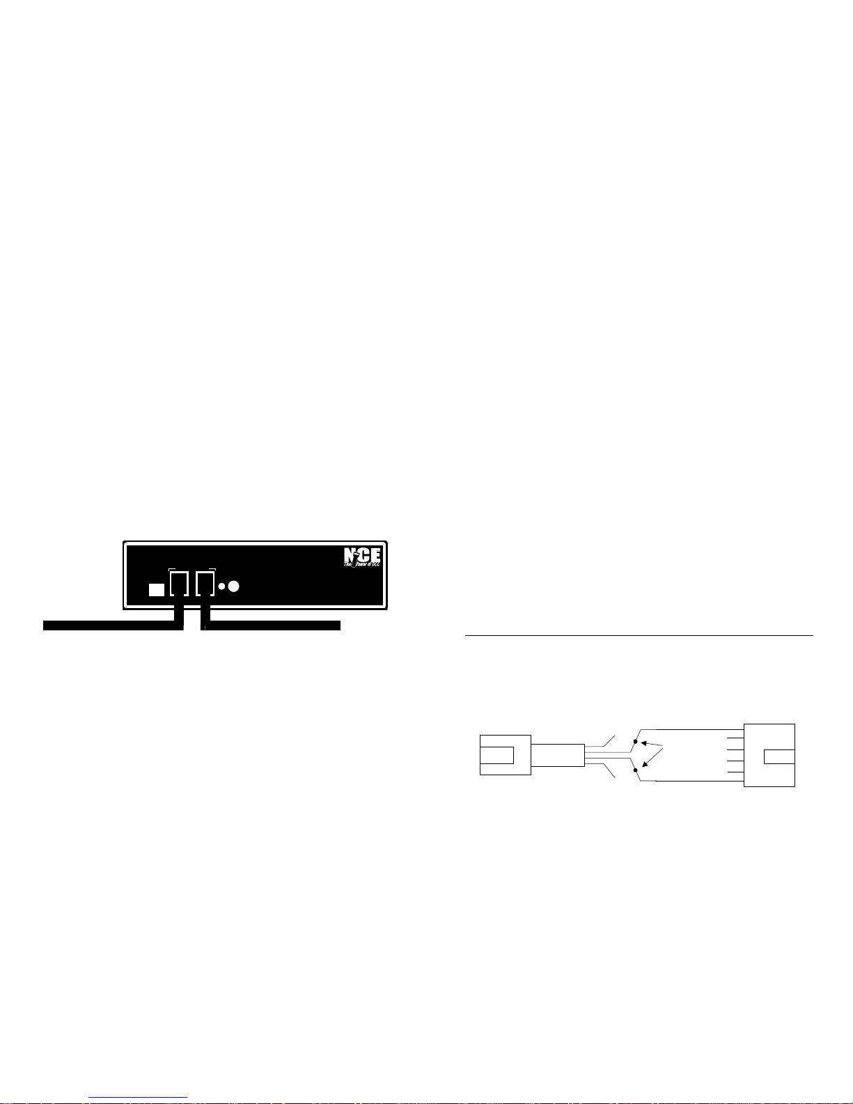
Use the supplied 7 foot cable to connect the PB5 to your
command station’s CONTROL BUS socket. The remaining
(unused) socket on the PB5 can be used to connect to other
Boosters in daisy chain fashion. Use only the 4-wire RJ-H
cable for this purpose. Longer cables may be used if more
distance is needed between power stations. The last power
station at the end of the daisy chain will have one empty
socket. The PB5 will place a nominal 6mA load on the
command station control bus.
STATUS LIGHT
Page 3
TRACK
STATUSPOWER
18VDC MAX.
PB5
FIVEAMPPOWER BOOSTER
CONTROLBUS
POWER PRO
From CommandStation
7 foot Cable Toother Power Boosters
This light will illuminate light steadily under normal
operations. Flashing indicates an abnormal or fault condition.
Here is a description of the various conditions indicated by
the status light.
Steady on - Track power is on and operations are
normal.
Rapid flash - No DCC signal from command station
(control bus cable is unplugged, programming track in
use, etc.)
Slow flash - Short circuit in the layout wiring, the layout
track or in a locomotive.
POWER SOCKET:
Input power from the outside power supply goes into the
PB5 via the round socket. Use ONLY the NCE supplied
P514 power supply.
TRACK VOLTAGE ADJUSTMENT
The track voltage can be changed between 12 Volts and
13.8 Volts by setting the switch on the P514 power supply.
CONNECTING THE PB5 TO OTHER SYSTEMS
WIRING TO A LENZ COMMAND STATION
This wiring diagram is provided for the operators that wish to
add an NCE power booster to their existing LENZ system.
Lenz does not provide a ground point.
Page 4
Red
Green
Cut off black wire
Cut off yellow wire
6 positionRJ-12
connector
Supplied4position
RJ-Hcable
Connection from Digitrax command station to NCE boosters
Blue
White
Yel
Grn
Red
Blk
NOTE: Connectoneof the NCE boostercoverscrews to the ground connectionof otherboostersinthesystem
ConnecttoNCEbooster
"ControlBus"jack
ConnecttoDigitrax
LocoNetjack
Splicewires
 Loading...