

Page 1
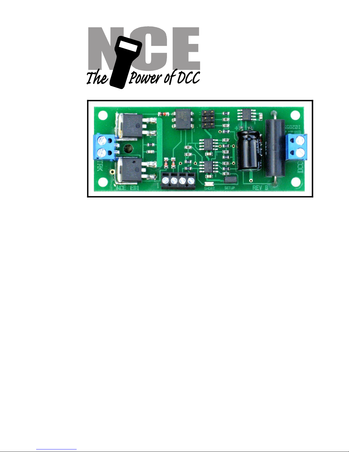
EB1
Circuit Breaker
$29.95
Electronic circuit breaker for use on DCC layouts only.
Features of the EB1:
Provides short circuit protection for one power district
Trip current adjustable for 2.5 to 8 Amps
Easy hookup using screw terminals , no soldering
Status indication LED
Additional output for remote LED
Optional manual reset
Adjustable short circuit response time
Adjustable power-up response time to accommodate startup of sound
decoder equipped loco motives
This book, schematics and artwork Copyright 2008
NCE Corporation Webster, NY 14580
05240225
05240225
Page 2
Description:
It is usually desirable to divide a layout into separate track power sections (power districts).
Multiple EB1 circuit breakers can be used to divide the power output of one DCC booster into
independent power districts each with its own short circuit protection. Note: The EB1 is
designed to be used only with DCC systems. It will not work with any power system other
than DCC.
Mechanical Installation:
The EB1 has 4 mounting holes that can be used to mount it to a convenient place on your
layout. We recommend using #4 x 3/4” round head wood screws with #4 flat washers. Do
not over tighten the screws. Lightly snug the screws up just enough to keep the circuit board
in place without bending it. Bending the circuit board can fracture the fragile ceramic
electronic components.
Electrical Connections:
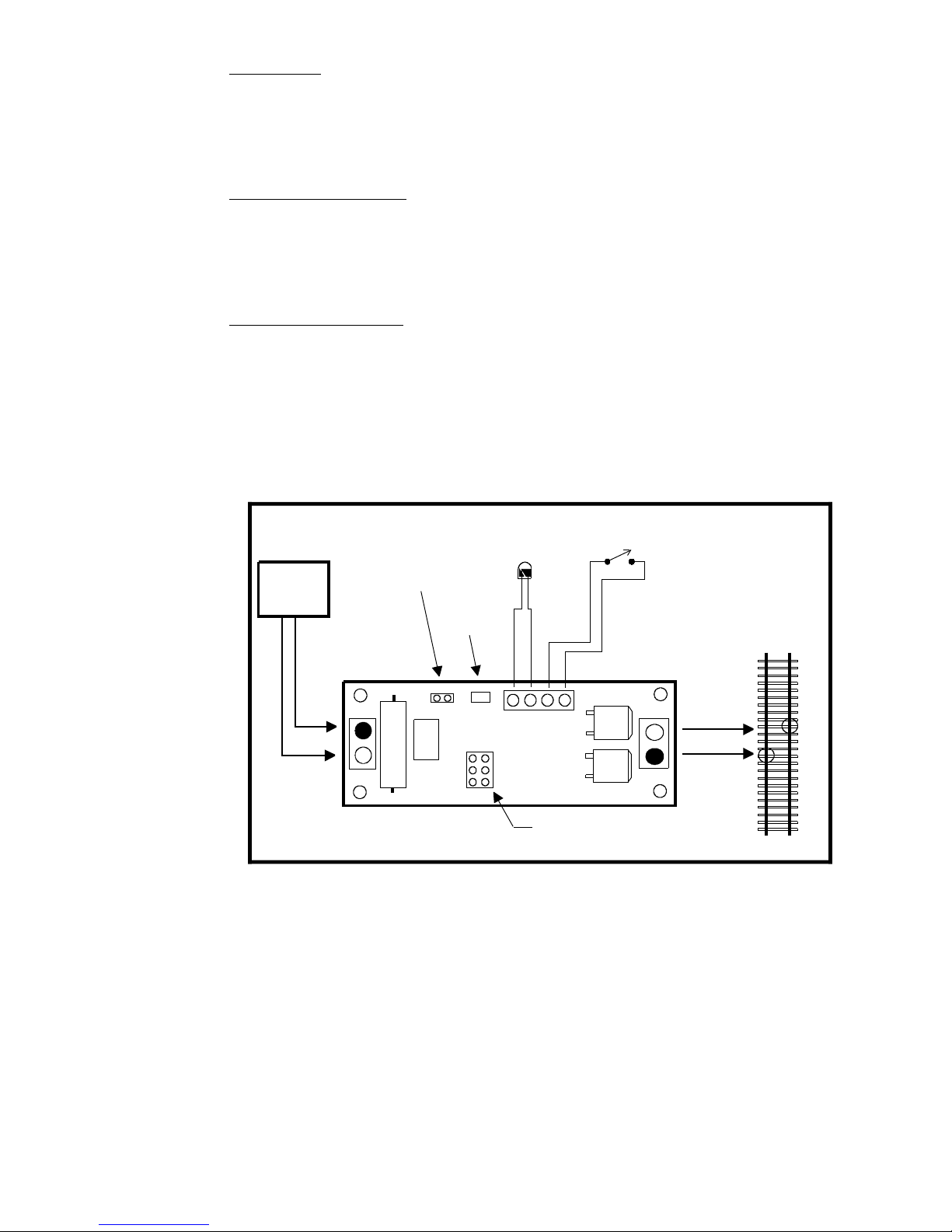
The diagram below illustrates the wiring of the EB1 to your layout. The terminal strips on the
EB1 accept up to #12 AWG wire. For distances to 20 feet (6.5 meters) from the booster to
the EB1 you should use at least #16 AWG wire, #14 for runs out to 40 feet and #12 for longer
runs. Wiring from the EB1 to the track should be the same gauge for runs of the same
distance. We recommend track feeder wires every 8-10 feet when using code 83 or larger
rail size. If you’re using code 70 or smaller rail we suggest feeders every 6 feet. Insufficient
feeders can cause enough voltage drop to prevent the circuit breaker from working. The
drawing below shows booster (DCC power) and track connections as well as hookups for
optional manual reset and a remote status LED.
Note: The screw terminals marked with black dots (drawing above) are directly connected
together on the EB1 circuit board. If you are using common rail make sure the terminals
marked in black above are connected to the common rail (left rail in the diagram). When the
EB1 “trips” only the screw terminals marked with an X are disconnected during a short circuit.
When the power and track connections are made the EB1 is ready to use. Factory settings
have been chosen to provide suitable operation with most HO and N scale layouts. If desired
you can fine tune the operating parameters of the EB1 to more closely match your DCC
system and layout using the information presented on the following pages. Before jumping in
and changing any settings we suggest trying the EB1 with the original factory settings.
**Last revised: 5 February 2008 Page 2 EB1
TRACK
LED
DCC
POWER
A
B
C
EB1
X
X
SETUP
JUMPER
MANUAL RESET
(optional)
1234
REMOTE
LED
(optional)
Jumpers to set trip current
Must be momentary
pushbutton type switch
STATUS
Page 3
Setting trip current:
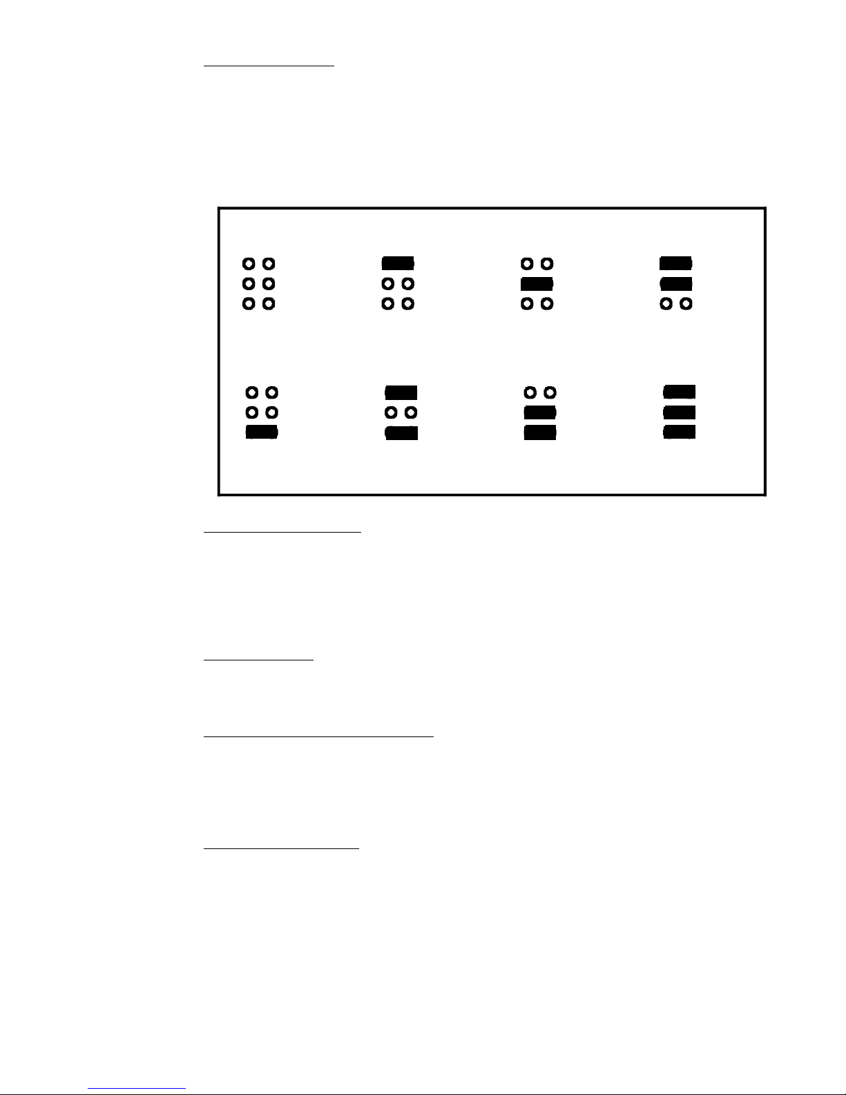
The EB1 comes from the factory with the trip current set to 2.5 Amps. You can set the trip
current for each district higher by using circuit “shunts”. Shunts are the small black plastic
pieces supplied with the EB1. If no shunt is installed the trip current is 2.5 Amps. The
diagram below illustrates the locations of shunts to set the trip current in 8 increments from
2.5 to 8 Amps.
To install a shunt simply slip it over the indicated pins on the circuit board. The diagram
below shows the settings.
Testing the installation:
After setting the trip current we recommend testing your wiring. The “quarter test” is the
fastest way to test your wiring. Use a coin or other piece of metal to short across the rails at
various places in a power district. The EB1 should trip and shut down the power district at
every place you short out the track. Once shut down the EB1 will try to restore power about
once every 2 seconds. If there is still a short the EB1 will kill the power again, until the short
is removed.
Status Indicator:
There is a status indicator LED near the “SETUP” connector. The LED will light steadily if
everything is OK. A flashing LED indicates the circuit breaker for the power district has
tripped. LED off usually indicates the DCC power booster is turned off.
Optional External Status Indicator:
You may connect an LED for use as a remote status indicator to terminals 3 and 4 of the the
EB1. This LED will duplicate the actions of the small status LED mounted on the EB1.
Current limiting resistors are already mounted on the EB1 so all you need is an LED. The
cathode (minus polarity) of the LED should be connected to terminal 4. Use the diagram on
page 2 as reference for connecting this LED.
Optional Manual Reset:
You may connect an external pushbutton switch (normally open type) as a manual reset to
recover manually from a short circuit. The EB1 must be setup for manual reset for this
feature to work (see the following section on Fine Tuning the EB1). The switch should be
connected between terminals 1 and 2. Use the diagram on page 2 as reference for
connecting this switch.
**Last revised: 5 February 2008 Page 3 EB1
A
B
C
A
B
C
A
B
C
A
B
C
2.5 AMP 3.5 AMP 4 AMP 5 AMP
A
B
C
A
B
C
A
B
C
A
B
C
6 AMP 7 AMP 7.5 AMP 8 AMP
TRIP CURRENT JUMPER SETTINGS
Black "bar" indicates location of shunt
Page 4

Two ways to setup the EB1:
Method 1:
Any DCC system that has OPs mode programming (Program On the Main) for locomotives
can program CVs. Whenever the “SETUP” shunt is installed the EB1 will respond to loco
OPS mode programming no matter what locomotive address is used. We recommend
choosing an address that is not in use on your layout (we use 9999). Remember that the
shunt must be installed to use this method of setting CVs. Do not forget to remove the
shunt when done programming.
Method 2:
If you have an NCE (or other system) that supports OPs mode programming of accessories
you can program CVs without having to install the “SETUP” shunt.
The EB1 comes from the factory preprogrammed to the accessory address of 2044 (the
accessory broadcast address).
To change the address:
Install the “SETUP” shunt
Press SELECT ACCY on your controller
Type in the new address you want to EB1 to use followed by ENTER
Press 1 (for NORMAL) when prompted on your controller
Remove the shunt
The EB1 will now respond to Accessory Programming at the address you just programmed.
You will not need to install the shunt again to program CVs when using PROGRAM
ACCESSORIES mode on an NCE system.
Fine Tuning the EB1
CV129 - Adjustment of short circuit response time (if necessary):
You can adjust the time delay between the occurrence of a short circuit and the time the track
actually gets shut down. The EB1 comes factory set to 16mS (16 milliseconds = 16
thousandths of a second). This setting has been chosen because it can be used without
problem on most layouts. You can lengthen this delay from 16ms (1/60th second) out to
512mS (1/2 second). Program CV129 to the number of milliseconds (divided by 16) you
desire between 16mS and 500mS. A value of 1 = 16mS, a value of 32 = 512mS, etc.
CV130 - Adjustment of short circuit shutdown time (if necessary):
You can adjust the time the track power stays off after a short circuit is detected. The EB1
comes factory set to 2 seconds. This setting has been chosen because it can be used
without problem on most layouts. You can change this delay from 16mS to 4 seconds.
Program CV130 to the number of milliseconds (divided by 16) you desire. A value of 1 =
16mS, a value of 128= 2 seconds, 256 = 4 seconds, etc.
CV131 - Manual reset enable.
If CV131 is set to 0 the manual reset is disabled and the EB1 will automatically try to turn on
track power after a short circuit. If CV131 is set to 1 the EB1 will not automatically restore
track power after a short circuit until a connection (usually with a pushbutton) is made
between terminals 1 and 2 of the four position terminal strip. You can also turn the track
power back on by selecting the accessory address and setting the accessory to ON (also
known as Normal, Thrown or +) .
**Last revised: 5 February 2008 Page 4 EB1
Page 5

CV132/133 - Accessory address
CV132 default = 143 high byte of accessory address
CV133 default = 191 Low byte of accessory address
Don't try to set these CVs by manually programming CVs.
Use the "setup" jumper method above to set the accessory address.
If manual reset is enabled, track power through the EB1 can be turned on/off (or turned back
on after a short circuit shutdown) by controlling the EB1 as accessory (turnout). ON/Normal
turn track power on and OFF/reverse turns it off/
CV135-CV146 - Custom Startup Table (Note: this if for the technically inclined)
The custom startup table provides a programmable method to pulse the track power on and
off several times before the EB1 tests for overcurrent. You can program the on and off times
in increments of 1mS. Generally you will not use this table with most boosters but it may be
useful with a booster that has weak startup capability.
An "off" time of 0 indicates the last entry of table. With the factory default of CV144 = 0
indicates the EB1 will not try to use the 6th "on" time.
If CV135 = 0 the table is disabled.
CV135 default = 0 Custom startup table initial "on" time
CV136 default = 4 Custom startup table initial "off" time
CV137 default = 8 Custom startup table 2nd "on" time
CV138 default = 4 Custom startup table 2nd "off" time
CV139 default = 16 Custom startup table 3rd "on" time
CV140 default = 4 Custom startup table 3rd "off" time
CV141 default = 32 Custom startup table 4th "on" time
CV142 default = 4 Custom startup table 4th "off" time
CV143 default = 80 Custom startup table 5th "on" time
CV144 default = 0 Custom startup table 5th "off" time
CV145 default = 0 Custom startup table 6th "on" time
CV146 default = 0 Custom startup table 6th "off" time
CV147 Factory reset
Set CV147 = 85 to do a factory reset of the EB1 to the following values.
CV129 default = 1 16mS allowable short circuit
CV130 default = 128 2 seconds power off time
CV131 default = 0 Manual reset off
CV132default = 143 High byte of accessory address2044
CV133default = 191 Low byte of accessory address 2044
CV135 default = 0 Custom startup table disabled
CV136 default = 4
CV137 default = 8
CV138 default = 4
CV139 default = 16
CV140 default = 4
CV141 default = 32
CV142 default = 4
CV143 default = 80
CV144 default = 0
CV145 default = 0
CV146 default = 0
**Last revised: 5 February 2008 Page 5 EB1
Page 6

EB1 Specifications:
Dimensions: ..............................3.75 x 1.25 inches
Max. input current:.....................10 Amps
Max. DCC voltage:.....................22 Volts
Short circuit response:............... 16mS to 512mS
Over current trip points:..............2.5 Amp +/- 75mA
3.50 Amp +/- 90mA
4.00 Amp +/- 120mA
5.00 Amp +/- 100mA
6.00 Amp +/- 150mA
7.00 Amp +/- 150mA
7.50 Amp +/- 100mA
8.00 Amp +/- 200mA
Ext. LED maximum current........17mA (300 Ohms in series with 5 volts)
Accessory address range...........1-2044 (2041-2044 are NMRA broadcast addresses)
Device Warranty
This device is fully factory tested and warranted against manufacturing defects for a period of 1 year. As the
circumstances under which it is installed can not be controlled, failure of the device due to installation problems can
not be warranted. This includes misuse, miswiring, or operation under loads beyond the design range of the device.
For warranty or non-warranty replacement send the device (and any payment, if required) to:
NCE Warranty Center 05240225
82 East Main St. 05240225
Webster, New York 14580
The terms Silent Running, Power Pro, ProCab, PowerCab , the NCE logo with “Power of DCC” slogan are trademarks of NCE
Corporation.
**Last revised: 5 February 2008 Page 6 EB1
 Loading...