

Page 1
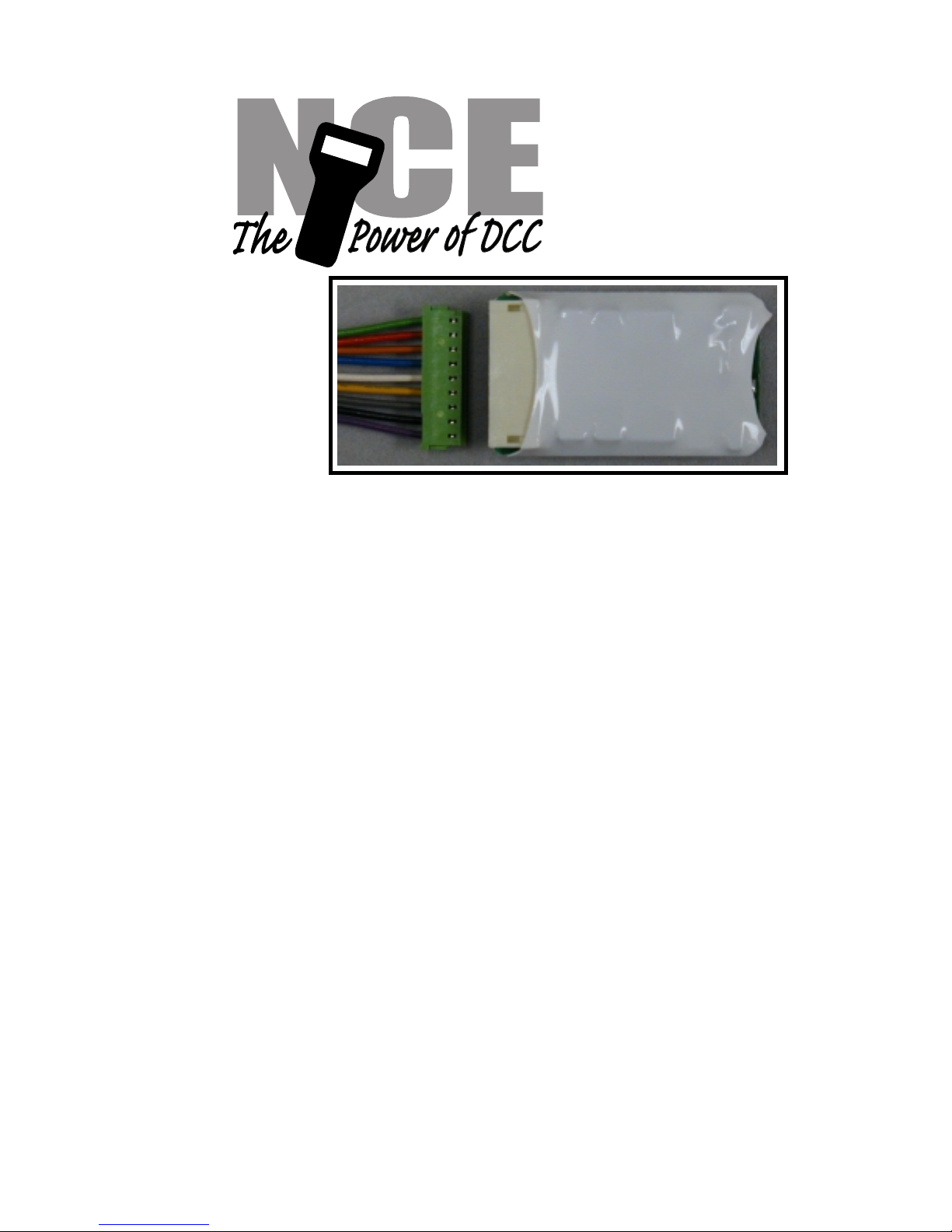
D15SR
Decoder
Top Side View of decoder
$29.95
Decoder version 3.5
Dimensions: 1.08 x 0.630 x .275 inches 27.5 x 16.5 x 7 mm
Convenient 9 pin plug and wiring harness makes it easy
to replace noisy decoders from other manufacturers
This is an EPF (extended packet format) decoder supporting:
Silent Running TM motor drive
Directly replaces noisy Atlas #340 or Digitrax DH150 series decoders
Torque Compensation for ultra smooth low speed performance
Programmable Start, Mid and Maximum speed works for all speed modes
Motor rating 1.3 Amp continuous, 2 Amp peak (stall)
Five function outputs each with independent lighting effects generators
Select from 15 different lighting effects (Mars, strobes, beacon, flicker, etc)
Lighting outputs can be mapped to different functions
Uploadable speed table interpolated to 128 speed steps
Decoder assisted consisting
Support for all forms of DCC programming
Decoder programming lock mechanism
Brake on DC feature assists automatic train control
Every attempt has been made to ensure this decoder complies with all applicable NMRA Standards
and Recommended Practices. NMRA Conformance test results on this decoder are available on
our website at www.ncedcc.com
This book, schematics and artwork copyright 2003
NCE Corporation Webster, NY 14580
Page 2
Installation Notes:
Caution: The D15SR decoder is covered with heat shrink tubing to protect it from short
circuits to the locomotive frame or wiring in the locomotive. Make sure there are no pinched
wires between the decoder and frame when replacing the body shell.
The most important part of a successful decoder installation is proper isolation of both
motor brushes from the track so that they are driven only by the decoder. Failure to isolate
the motor will definitely damage the decoder. Damage caused by failure to isolate the
motor is not covered by the decoder warranty.
To separate the 9 pin wire harness from the decoder: Firmly grip the decoder by the
sides, at the connector end with one hand. W ith your other hand firmly grip all 9 wires
between your thumb and forefinger about 3/4" back from the plug. Use a steady, gentle
pull. It is important to evenly distribute the force across all 9 wires. Try a small
side-to-side rocking rocking motion if the plug is reluctant to come out of the decoder.
DC BRUSH
MOTOR
RIGHT RAIL
LEFT RAIL
(Fireman's Side)
HEADLIGHT
REARLIGHT
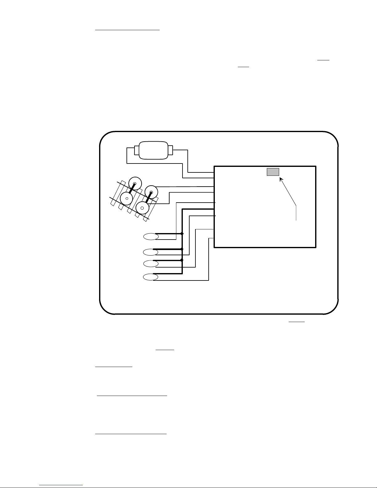
Note 1: The function common (blue wire) is the posi t i ve l ead provi di ng recitfied DC voltage. If you
elect to NOT use the common, power the light or other device from either track power pickup for
"half-wave" operation.
(Engineer's Side)
F1
F2
GRAY
ORANGE
RED
BLACK
WHITE
BLUE
YELLOW
GREEN
VIOLET
WARNING: To prevent decoder damage:
always make sure the motor brushes are
properly isolated before applying power.
Motor Motor +
Right Track Power Pickup
Left Track Power Pickup
Output 1 (F0)
Light Common ( See note 1)
Output 2 (F0)
Output 3 (F1)
Output 4 (F2)
Output 5 (F3) available
as a solder 'pad' on
bottom of decoder
Always test your decoder installation on an current limited programming track before
trying it on full track power.
We recommend that the first full power testing be done on regular DC. If the track pickup polarity is
reversed you will want to correct this for proper analog mode operation. The decoders should be
driven by a good quality smooth
DC power unit. Power packs with pulse power systems such as
"tracking control", etc. will give unpredictable operation.
DC Lighting:
This decoder remembers which functions are on or off between uses. If a function was on during
DCC operation it will be on during DC operation. Lighting effects (Mars, flicker, etc) will also
operate. Lighting effects work best in DC mode when used with LEDs.
Recommended Lighting:
If you use LEDs we recommend a 1K ohm 1/4 Watt series resistor in each function lead
➙ Miniatronics #12-310-05 Yellow Glo White LEDs.
➙ Richmond Controls (or equivalent) Golden White LEDs.
➙ Miniatronics #18-712-10 (12v) or #18-014-10 (14v) incandescent bulbs
Function
bulbs (about 10 times their normal operating current) function outputs are rated at 40mA each if
used with incandescent bulbs. We recommend the Miniatronics part number mentioned above. If
you wish to use 50-100mA rated lamps we recommend a 22 ohm 1/4 Watt series resistor in
function leads with each bulb (this will also greatly extend bulb life).
output ratings: Due to the high in-rush current of incandescent grain-of-wheat type
**Last revised: 17 November 2003 Page 2 D15SR
Page 3
Fine tuning locomotive operation
The factory settings normally provide good performance for most locomotives in H O-Scale. You
may want to improve or fine tune performance by adjust the starting characteristics or top speed .
There are 6 CVs that define:
➙ The voltage at which the motor starts
➙ How often and how hard the motor gets kicked a slow speeds to keep it turning smoothly.
➙ The maximum motor speed
➙ The mid speed range response characteristics or ‘speed curve’.
➙ Compensation for a motor that runs faster in one direction
Start Voltage - CV2 (Vstart):
This is the amount of voltage sent to the motor when first starting up. We set CV2 so the
locomotive is almost able to maintain movement at speed step 1. We then use CV116 and 117 to
apply enough torque compensation to keep it turning on speed step 1. Typical values for CV2 are
in the range of 0-35.
Torque compensation kick rate - CV116:
How frequently the motor is ‘kicked’ at slow speed. Typical adjustment is 2 to 4. The smaller the
number the more often the motor gets a brief voltage ‘kick’. Factory default is 0 (off). A value of 1
applies kicks continuously. The maximum practical value is about 6.
Torque compensation kick strength - CV117:
How hard the motor is ‘kicked’ at slow speed. Typical adjustment is 4 to 25 The larger the number
the more voltage is applied in each ‘kick’. The strength of these kicks fade out ratiometrically as
speed is increased providing a smooth transition to normal motor operation. Factory default is 0
(off), usable range 0-50.
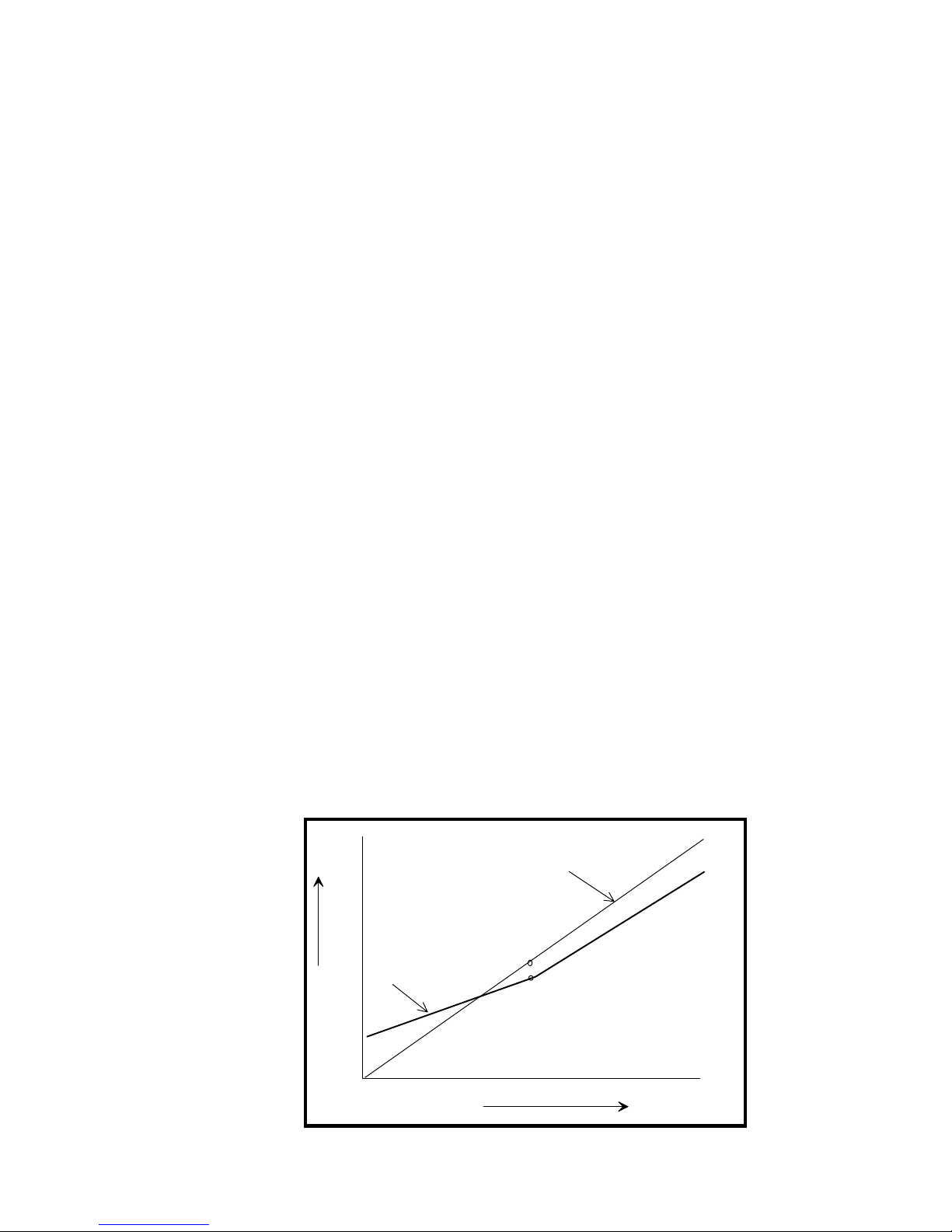
Vmax - CV5: If your locomotive runs too fast you can use CV5 to lower its maximum speed.
Setting CV5 to 255 uses the maximum possible voltage to run the motor when full speed is
requested. Set CV5 to a smaller value to reduce the top speed. A value of 128 will yield
approximately ½ full voltage to the motor at top speed. 192 will provide about ¾ full voltage. All
speeds from the middle speed step to the maximum will be proportionally reduced (see diagram). If
CV5 is set to 0 the decoder will use 255 for maximum speed. Always make sure CV5 is greater
than CV6 to avoid erratic operation.
Vmid - CV6: CV6 determines how the motor responds through its middle speed ranges to
advancement of the throttle. If you set CV6 lower than half the maximum speed you’ll have smaller
increases in motor speed through the lower speed ranges. Then, as you hit the upper speed
ranges there will be larger increases between speed steps. In the diagram below you can see this
best illustrated by the ‘customized’ line. If you set Vstart larger than 0 you’ll will most likely want to
raise Vmid so a reasonable slope is maintained in the ‘speed curve’. If CV6 is set to 0 the decoder
will use 127 as the value. If you use high values in CV117 you will want to increase CV6 by a
proportional amount to keep a smooth acceleration curve.
Reverse trim (also forward trim) - CV95:
Values from 1-127 make decoder run faster in reverse than forward. 1 is one speed step faster in
reverse, 2 is two steps faster, etc.
Values from 129-255 make decoder run faster in forward than reverse. 129 is one speed step
faster in forward, 130 is 2 speed steps faster, etc. 0 and 128 add nothing to either direction .
**Last revised: 17 November 2003 Page 3 D15SR
255
factory default
192
128
customized
064
Vstart
Voltage
000
1 1286432 96
Speed steps
Vmax
Vmid
Motor 'Speed Curve'
Page 4

Effects programming (and function mapping) examples
Ditch lights:
What we want to do:
➡ Use outputs 3 and 4 for the left and right ditch lights
➡ They will be controlled by F2 which is the HORN button on most DCC systems
➡ They should continue flashing for 5 seconds after the HORN button is released
How to do it:
✓ Program outputs 3 and 4 to both be activated by F2. Set the F2 mapping CV (CV36) to 12.
We get the value of 12 by adding the ‘values for output 3 and output 4 on the F2 line of the CV
mapping table on page 6.
✓ Program outputs 3 and 4 for ditch light operation. Set CV122 to 56 and CV123 to 60. Using
these values the lights will be ‘qualified’ by the headlight AND function 2. The headlight must
be on for the ditch lights to be activated by F2. Type 1 ditch lights are on constantly on when
the headlight is on and alternately flash when the horn is blown. Type 2 ditch lights are
normally off until the horn is blown. This example is for the more common Type 1. If you
prefer Type 2 use EFX values 52 and 48 instead of 60 and 56.
✓ CV118 sets the amount of time the ditch lights stay flashing after the horn (F2) is deactivated.
The time is measured in 1/4 second intervals, for a hold time of 5 seconds put a value of 20 in
the CV118.
✓ One last thing: Set CV35 to 0 so output 3 is not also controlled by F1
Mars Light:
What we want to do:
➙ Use output 3 (marked A on decoder) for a Mars light.
➙ It is to be on in the forward direction only
How to do it:
✓ Output 3 is already activated by F1 (factory default setting of CV35=4).
✓ Configure output 3 as a forward only Mars light. Set CV122 to 9. We get the value of 9 by
using 8 (Mars Light) plus 1 (output operates only in forward direction)
Rule 17 lighting:
Rule 17 refers to how the locomotive engineer operates the locomotive headlights during the
running of the train. The rule varies from road to road but generally requires the dimming of the
headlight(s) when in a siding waiting to meet another train, passing through passenger stations o r
moving within yard limits.
What we want to do:
➙ Use output 1 for the Headlight
➙ The headlight is to be on bright in both directions of locomotive travel
➙ We also want to be able dim the headlight
➙ Use output 2 for the rear light. It is to come on in reverse, off in forward
How to do it:
✓ Output 1 is already activated by F0 (factory default setting of CV33 =1).
✓ Configure output 1 as a standard output, on in both directions, yet dimmable when F4 is
activated. Set CV120 to 32 (20 hex). You can optionally set CV120 to 36 is you want F8 to
control the dimming instead of F4.
✓ Configure the rear light to be on in reverse and off in forward operation: Set CV121 to 2
Switcher:
What we want:
➙ Headlights that dim in the opposite direction that the locomotive is travelling
➙ Use output 1 as Headlight and output 2 as Rearlight
How to do it:
✓ Outputs 1 and 2 are already activated by F0 due to the factory default settings.
✓ Configure output 1 as bright in forward dim in reverse . Set CV120 to 44 (2C hex)
✓ Configure output 2 as bright in reverse dim in forward . Set CV121 to 40 (28 hex)
**Last revised: 17 November 2003 Page 4 D15SR
Page 5

Description of EFX configuration CVs
CV120 - Lighting effect configuration for output 1 (White wire).
CV121 - Lighting effect configuration for output 2 (Yellow wire).
CV122 - Lighting effect configuration for output 3 (Green wire).
CV123 - Lighting effect configuration for output 4 (Violet wire).
CV124 - Lighting effect configuration for output 5 (solder pad).
Each output wire can select from 15 different lighting effects by using its associated EFX
configuration CV. Pick the value for the CV from the table below, add 1 or 2 if you want
the effect to be directional (footnotes 2 and 3), then add 128 if you are using a white LED
for the effect. Ditch lights should not be made directional, they’re not dierectional in real
life.
1248163264128bit weight
bit name
1
Effect configuration---LED
REV
2
FWD
3
for CV
48
52
56
60
Description of lighting effectValue
Standard on/off function output0
Firebox flicker (brighter when accelerating)4
Mars light8
Rotary Beacon12
Gyralight16
Double Strobe20
Strobe A24
Strobe B (alternates with Strobe A)28
Dim when F0 and F4 on, otherwise bright32
Dim when F0 and F8 on, otherwise bright36
Dim in forward, bright in reverse40
Dim in reverse, bright in forward44
Type 2 Right Ditch light, effect on if F2 on,
output off otherwise
Type 2 Left Ditch light, effect on if F2 on, output
off otherwise
Type 1 Right Ditch light, effect on if F0 and F2
on, bright if F0 on and F2 off, off if F0 off
Type 1 Left Ditch light, effect if F2 and F0 on,
bright if F0 on and F2 off, off if F0 off
Hex (for
Digitrax users)
0
4
8
0C
10
14
18
1C
20
24
28
2C
30
34
38
3C
1 - Functions are designed to use 12-16 volt 30-40ma incandescent lamps. If you are using a
white LED (with 1K limiting resistor) add 128 to the CV value.
2 - If you want the function to be active only in the reverse direction add 2 to the CV value
3 - If you want the function to be active only in the forward direction add 1 to the CV value
**Last revised: 17 November 2003 Page 5 D15SR
Page 6
Description of function mapping CVs:
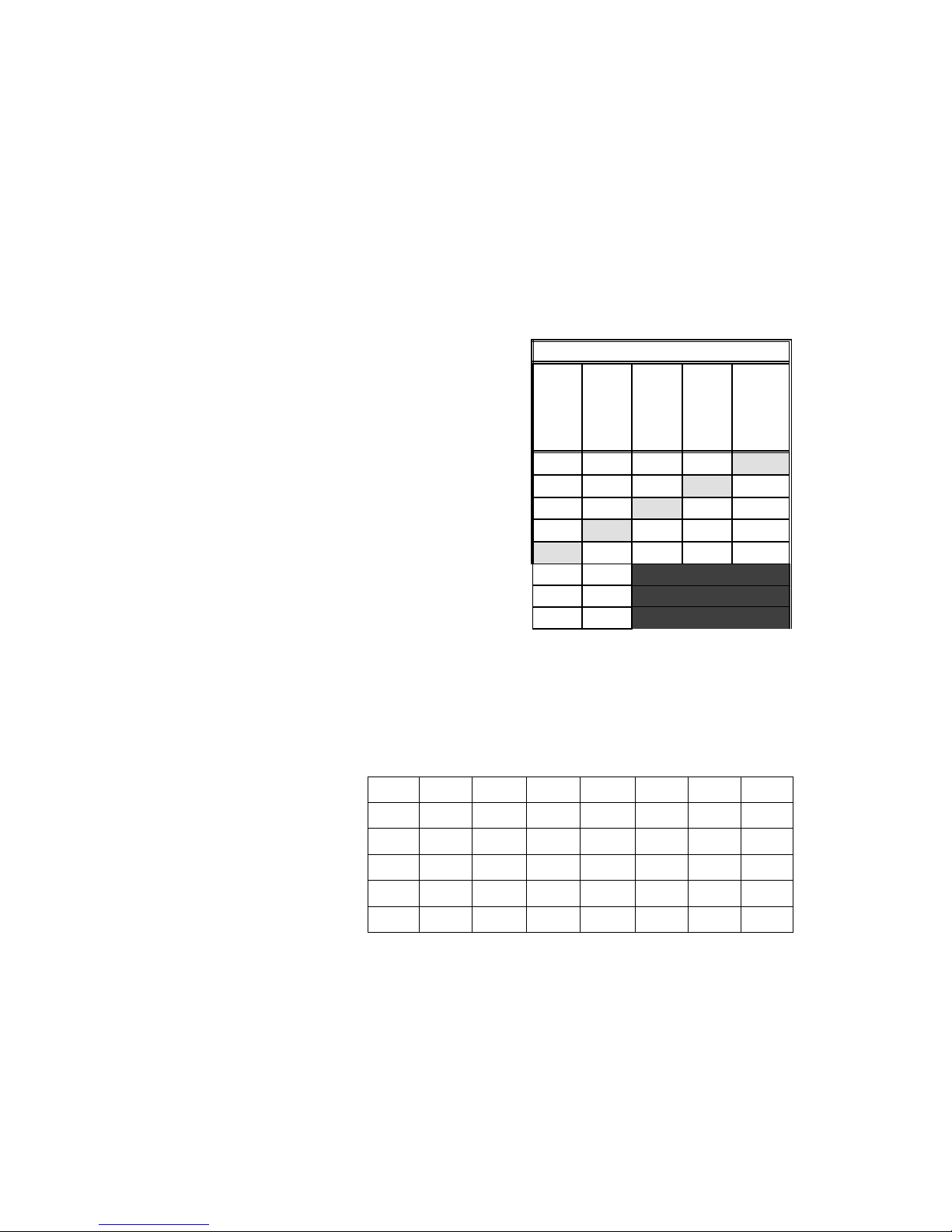
Function mapping can change which outputs are controlled by a function command from
your handheld cab. It is possible to have one command control several outputs. In the
table below each row corresponds to a function mapping CV and each column indicates
an output number. The bold number in a column is the factory default. Programming the
CV to the value under an output number will change that output to be controlled by that
function number. In the table below the factory value of CV35 is 4 which means F1 will
control Output #3. If you want F1 tocontrol output 4 program CV35 to 8. If you want F1 to
control both outputs 3 and 4 add the two values for those outputs together (4+8=12) and
program CV35 with 12.
Note in this decoder CV33 and CV34 operate identically. They are not
directional...directionality is provided in the EFX configuration CV for each output.
Factory default function mapping values
OUTPUT NUMBER
12345
CV33 F0 Fwd
CV34 F0 Rev
CV35 F1
CV36 F2
CV37 F3
CV38 F4
CV39 F5
CV40 F6
Solder pad
16
16
Violet wire
816
8
12
12
12
Recommend dropping resistors if using 1.5 volt bulbs
Track Voltage
15ma
30ma
40ma
50ma
60ma
80ma
1
1
12
124
1248
1615.51514.51413.51312.5Bulb Current
White wire
Wattage
Green wire
4816
Yell ow wire
24816
2
4
¼ watt910910820820750720680680
½ watt470430430390390360360330
1 watt330330300300300270270240
1 watt270270240240220220200200
1 watt220220200200200180180160
2 watt160160160150150130130120
**Last revised: 17 November 2003 Page 6 D15SR
Page 7
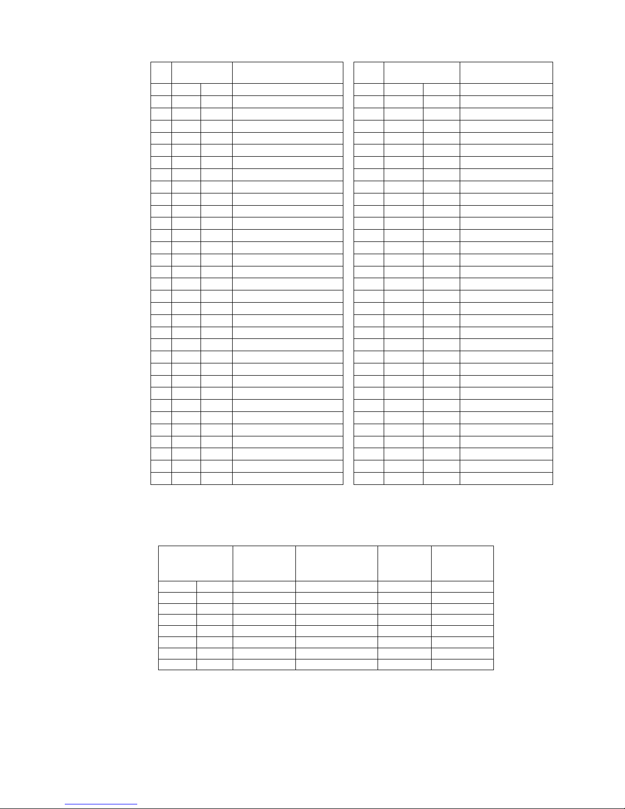
Factory default values for decoder Configuration Variables (CVs)
CV
11
15
16
17
18
19
21
22
23
24
29
30
33
34
35
36
37
38
39
40
41
42
67
68
69
70
1
2
3
4
5
6
7
decimal
3
0
0
0
0
0
35
0
0
0
192
0
0
255
63
0
0
6
0
1
2
4
8
16
4
8
16
0
0
0
0
0
0
hex
03
00
00
00
00
00
23
00
00
00
C0
00
00
FF
3F
00
00
06
00
01
02
04
08
10
04
08
10
0
0
0
0
0
0
CVDescriptionDefault value
hex
decimal
71short address
72start voltage
73acceleration
74deceleration
75maximum speed
76mid speed
77decoder version
78Packet timeout value
79Programming “key”
80Programming “lock”
81long address high byte
82long address low byte
83consist address
84consist functions F1-F8
85consist function FLF,FLR
86acceleration adjust
87deceleration adjust
88decoder configuration
89error/reset register
90Output(s) controlled by F0
91Output(s) controlled by F0
92Output(s) controlled by F1
93Output(s) controlled by F2
94Output(s) controlled by F3
95Output(s) controlled by F4
116Output(s) controlled by F5
117Output(s) controlled by F6
118not used
120not used
121alt spd table step 1
122alt spd table step 2
123alt spd table step 3
124alt spd table step 4
0
0
0
0
0
0
0
0
0
0
0
0
0
0
0
0
0
0
0
0
0
0
0
0
0
0
0
20
1
2
0
0
0
0
0
0
0
0
0
0
0
0
0
0
0
0
0
0
0
0
0
0
0
0
0
0
0
0
0
0
14
01
02
00
00
00
DescriptionDefault value
alt spd table step 5
alt spd table step 6
alt spd table step 7
alt spd table step 8
alt spd table step 9
alt spd table step 10
alt spd table step 11
alt spd table step 12
alt spd table step 13
alt spd table step 14
alt spd table step 15
alt spd table step 16
alt spd table step 17
alt spd table step 18
alt spd table step 19
alt spd table step 20
alt spd table step 21
alt spd table step 22
alt spd table step 23
alt spd table step 24
alt spd table step 25
alt spd table step 26
alt spd table step 27
alt spd table step 28
reverse trim
torque kick rate
torque kick strength
ditch light hold time
output 1 EFX generator
output 2 EFX generator
output 3 EFX generator
output 4 EFX generator
output 5 EFX generator
Configuration of CV29 settings:
Table of commonly used values for CV29
Value for CV29
decimal hex
Hex numbers are provided for early Digitrax users
Notes:
If you want to reverse the direction of travel on DCC increase the value for CV29 by one (this
also reverses all directional lighting).
If you want to reverse the DC direction reverse the track pickup wires.
**Last revised: 17 November 2003 Page 7 D15SR
Long/Short
Address
Uploadable/Facto
ry Speed table
Speed modeAnalog
(DC)
operation
28/128noFactoryShort20
28/128yesFactoryShort66
28/128noUploadableShort1218
28/128yesUploadableShort1622
28/128noFactoryLong2234
28/128yesFactoryLong2638
28/128noUploadableLong3250
28/128yesUploadableLong3654
Page 8

Configuration Variables used by V3.5 Decoders
CV1 Short decoder address; 1-127 valid
CV2 Start Voltage (useful range 0-100)
CV3 Acceleration rate (each unit = 7mS between speed steps) 255 max.
CV4 Deceleration rate (each unit = 7mS between speed steps) 255 max.
CV5 Vmax, speed at highest speed step. 0=use factory default of 255
CV6 Vmid, speed (on a scale of 1-255) at speed step 7,14,or 63. 0=use default of 127
CV7 Decoder version number. This decoder is 35 which means version 3.5
CV8 Manufactuer ID. NCE = 11 (0B hex)
CV11 Packet timeout value (in ½ second increments) Time the decoder will wait before braking to a
stop after running into a section of track with DC power. 0=Don’t brake
CV15 Decoder programming lock “KEY”. This CV is always programmable even when “locked”
CV16 Decoder programming lock ID. When CV15=CV16, programming is unlocked and the
decoder will respond to programming commands. If CV15 is not equal to CV16 then
decoder programming is locked and it will not program (except CV15) or read.
CV17 High byte of long (4 digit) address
- bit 6,7 always= 1
- bits 0-5 are upper 6 bits of address
CV18 Low byte of long (4 digit) address
CV19 Consist address. (0 or 128 = no consist active)
- bits 0-6 short consist address (1-127 valid)
- bit 7 0= direction is normal, 1= direction is reversed
CV21 Functions active in consist mode. Bit 0 controls F1,bit 1=F2, bit 2=F3, etc.
- bit 0 - 1=function can be controlled at consist address, 0 = no consist control
CV22 Functions active in consist mode. Bits 0,1 control FLF and FLR respectively
each bit 1=function can be controlled at consist address, 0 = no consist control
CV29 - bit 0 1= direction of operation is reversed, 0= direction is normal
- bit 1 1=28 speed mode (always enabled)
- bit 2 1= analog operation mode enabled, 0 = disabled
- bit 4 1= alternate speed table active, 0= use table defined by CV2,5,6
- bit 5 1= use long address in CV17/18, 0= use short address CV1
- bits 3,6,7 are ignored by the decoder
CV30 Set this CV to 2 on the programming track and the decoder will reset to factory settings.
CV33-CV39 function mapping CVs for F0-F5
CV67-CV94 Uploadable speed table steps 1-28 (128 speed mode calcu lates intermediate steps)
CV95 Reverse trim, values 1-127 add to reverse speed, values 129-255 add to forward speed
CV116 Torque kick rate - number of 16ms periods in a row that motor is ‘kicked’ with voltage pulse
CV117 Torque kick strength - how much voltage is used to kick the motor at slow speeds. Reduces
to 0 as speed is increased.
CV118 Ditch light hold time (in ¼ second increments) after F2 goes off.
CV120-CV124 Effects configuration registers for outputs 1-5
CV NOTES: All CV numbers not listed above may be programmed but not used by the decoder. This
decoder supports all DCC programming methods.
Formula for computing the long address if using a Lenz SET01 or SET02:
If using a Lenz SET01, SET02, SET90, SET100 or other entry level system, use paged programming
mode and see below for programming long addresses.
CV17 = 192 + (the whole number portion of the long address divided by 256)
CV18 = the remainder after the long address is divided by 256
CV29 = 34 if analog mode disabled, 38 if analog mode enabled
Decoder Warranty
This decoder is fully factory tested and warranted against manufacturing defects for a period of 1 year. As the
circumstances under which this decoder is installed can not be controlled, failure of the decoder due to installation
problems can not be warranted. This includes misuse, miswiring, operation under loads beyond the design range
of the decoder or short ciruits in the locomotive manufacturer’s factory wiring. If the decoder fails for non-warranted
reasons NCE will replace the decoder, no questions asked, for $10 U.S. plus $2 shipping. For warranty or
non-warranty replacement send the decoder (and any payment, if required) to:
NCE Warranty Center
899 Ridge Road
Bar Code
Webster, New York 14580
The terms Silent Running, Powerhouse Pro, Power Pro, SmartCab, ProCab, Switch-It, Snap-It, the NCE logo with “Power of DCC”
slogan and EFX are trademarks of NCE Corporation. Digitrax is a trademark of Digitrax Inc.
**Last revised: 17 November 2003 Page 8 D15SR
 Loading...