

Page 1
NATIONAL CONTROL DEVICES
Time Activated Relay Controllers
Taralist Quick Start Guide
Page 2

N A T I O N A L C O N T R O L D E V I C E S
Taralist
Time Activated Relay Controllers
National Control Devices, LLC
PO Box 455
Osceola, MO 64776
Phone 417.646.5644 • Fax (866) 562-0406
© Copyright 2013
All Rights Reserved.
Notice: Portions of this manual require internet access.
Page 3
http://www.controlanything.com/Relay/Device/ZUSB
IMPORTANT: Taralist firmware has been re-written.
If your controller is identified as a ‘Taralist Enhanced’ in Base Station
software, then your controller is capable of accepting commands at
high communications speeds.
Older versions of the firmware will require a 1ms delay between
communication bytes.
NCD STRONGLY ENCOURAGES A FIRMWARE UPGRADE IF YOU
ARE NOT USING TARALIST ENHANCED FIRMWARE.
Return your device to NCD, and we will upgrade your firmware free of
charge including return shipment.
All customers are STRONGLY ADVISED to purchase at least ONE
USB Communication Module. This communication module may be
used to recover a controller or to reconfigure a controller should there
be an accidental loss of communications. NCD Tech support may be
unable to assist customers who do not have a USB Communications
Module available for troubleshooting purposes.
Purchase USB Communications Module from our website at this link:
NOTICE:
Page 4

Table of Contents
Introduction .............................................................................. 1
Hardware Reference ................................................................ 3
Getting Started .......................................................................................... 3
Onboard Batter Backup ............................................................................ 4
Controlling Relays ..................................................................................... 6
Break Away Tabs ...................................................................................... 7
Taralist Configuration ............................................................... 8
Understanding Events ............................................................................ 11
Adding/Removing Events ....................................................................... 12
Defining Time .......................................................................................... 13
Midnight Backup Buffer ........................................................................... 14
Editing Protected Data ............................................................................ 15
Computer Control of Taralist ......................................................... 16
Command Set ........................................................................ 18
Relay Logic ............................................................................ 23
Electrical Specifications .......................................................... 26
Maximum Rating ..................................................................................... 26
Technical Support ..................... Error! Bookmark not defined.
Contact Information .......................... Error! Bookmark not defined.
Notice: ....................................................... Error! Bookmark not defined.
Page 5

Notice:
This manual will guide you through the setup and use of all Taralist Series relay
controllers. Following this manual in the sequence outlined is absolutely essential to
proper understanding and use of Taralist Series Controllers. Please review the
entire manual BEOFRE contacting NCD technical support. NCD technical support
staff will direct your questions to this manual when applicable.
Page 6

Chapter
1
T
Introduction
he Taralist Series relay controllers represent a significant advancement in the
evolution of the NCD product line. The Taralist Series controllers represent
many foundation technologies that will significantly strengthen our product
offerings in the years to come.
The Taralist Series of controllers are the first time-controlled devices we have ever
developed. This new architecture allows powerful computer-based configuration
without writing a single line of code. Taralist controllers are the first to offer a
Autonomous time controlled at any time, and even change settings in the
configuration through a direct USB connection or using a wireless 802.15.4 or
ZigBee Mesh Interface. The Taralist Series are manufactured using Surface
Mount Technology. A Break Away design has been implemented to meet the
requirements of customers who need an enclosure AND to customers who need
the smallest possible size. Break Away tabs allow the user to “break” off the outer
edges of the circuit board for a smaller profile. This type of controller in
conjunction with several other “no programming required” devices represent the
future direction of National Control Devices.
Who’s Qualified to Use the Taralist Series?
Anyone. The Taralist Series Controllers are one of the most user-friendly devices
we have ever manufactured. Whether you are an electronics engineer or home
hobbyist, anyone is qualified to use the Taralist Series controller provided this
manual is carefully studied.
How do the Taralist Series Controllers Work?
The Taralist Series Relay Controllers are configured using a computer (either using
wireless or a direct USB connection). Once configured, a Taralist controller will
operate without a computer. At any time, a computer may monitor the Taralist
Device, Activate Relays, or Change Configuration settings. A computer can take
over a Taralist or a Taralist can operate autonomously (without a computer). The
NCD Base Station software provides 1000 User Configurable events where a relay
or group of relays can be turned on or off. It’s that easy.
Once the Taralist is configured, it will run through the list of events sored in it’s
on board memory every second to look for a match with the current time. If a
match with the current time and a configured event is discovered, it will execute
the event.
1
Page 7

Order of Operations
There is a general process to learning and using a Taralist Series relay controller,
this manual will follow the two sequences, covering the Learning Cycle and the
Usage Cycle. Optionally, users may want to consider exploring the Advanced
Applications to unlock some of the most powerful features.
Learning Cycle
1. Hardware Reference (getting to know the hardware)
2. Communications
3. Configuration Overview
4. Building a Custom Configuration Profile
5. Loading and Saving Configuration Profiles
6. Understanding Relay Control
7. Testing a Taralist Controller
8. Controlling Devices with a Taralist Controller
9. Troubleshooting a Taralist Controller
Usage Cycle
1. Configuration
2. Testing
3. External Device connection
Advanced Application
1. Remote Configuration
2. Using a Computer to Take Over a Relay
3. Giving Relay Control Back to Taralist Logic
4. Changing the Time Compensation
5. Using the Midnight Buffer
2
Page 8

Chapter
2
T
Hardware Reference
Getting Started
here is no better place to start than from the beginning. This guide will lead
you through the understanding and use of you Taralist Series relay controller
in a sequence that will help get you started from the ground up.
Before contacting NCD technical support, make sure that you have thoroughly
read this guide. Most questions will be covered in this guide and NCD technical
support staff has been instructed to direct your questions to this manual when
appropriate. Please take advantage of the efforts we have invested in building a
complete and comprehensive product manual. This will save you time and allow
our technical support engineers to focus on product development.
3
Page 9
INCORRECT
Correct
Correct
Onboard Batter Backup
Lithium Ion Battery Backup
Each Taralist controller has a battery installed on it. This battery’s main purpose
is to keep the Taralist clock running if power is disconnected; otherwise, every
time you unplug and move the controller you would have to reset the time in it.
This battery will keep the Taralist clock running for up to two months, cut there
are some things you need to know.
The Taralist onboard battery backup is used to run the Taralist clock only, it will
not allow the controller to function and process events. You will not be able to
run the controller on this battery alone, an external power source is required for
processing events and controlling relays.
Charging the Onboard Battery
The onboard battery is charged when the device is attached to a power source.
You can control how fast the battery is charged by Editing Protected Data (page
14). This is very useful as you can charge the battery very quickly or very slowly.
Charging the battery slowly will increase the battery’s life, so whenever possible we
recommend leaving the Charge level to 1.
Getting the Best Life out of the Battery
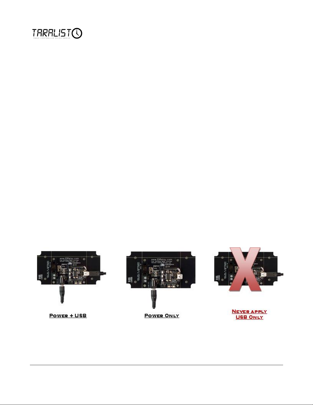
It is recommended to charge the battery slowly. Also make sure you have a power
source plugged into the controller when a USB cable is connected to the device.
If a USB cable is attached to the device but no power supply is connected, this will
drain the battery very quickly as the controller will not be able to properly enter
sleep mode.
4
Page 10

Understanding Outputs
Taralist Controllers are capable of controlling up to 256 Relays from only one
Taralist CPU. These controllers are available with 1, 2, 4, 8, 16, 24, and 32 relays
on a printed circuit board as well as a small controller with only an XR expansion
port instead of relays. XR Expansion Relays may be added to the XR Expansion
Port at any time giving you as many relays as you need (up to 256).
A relay is similar to a switch. The only difference between a switch and a relay is
the actual mechanism for changing the on/off status of the switch. On a switch,
you manually push on a piece of metal or plastic to operate the switch. On a relay,
an electric current is used to operate the switch. We will use the work “relay to
indicate a switch that is controlled by the Taralist controller.
Relays do NOT provide a voltage output. They provide a contact closure output,
exactly like the terminals found on a light switch at your local hardware store.
Wiring to a relay will be slightly different depending on the model of Taralist
controller you choose.
Some relays, such as the 5A and 10A versions, have a screw terminals that can
accept 12 Gauge or smaller wire. Other versions, such as the 20A and 30A relays,
have a .250” Quick Connect terminal (the appropriate mating connector can be
found at any hardware or automotive supply store). Our 20A HP series relays will
accept wires as large as 10 Gauge.
Again, relays do not provide a voltage output. They ONLY switch whatever
voltage you supply into the relay.
Relays are available in SPST, SPDT, and DPDT configurations. In addition, both
Mechanical and Solid State relays will be supported by the Taralist series. If you
are unfamiliar with the different versions of relays available, you can review
this article, which explains these relay types in great detail. The article will help you
determine the best type of relay for your application, showing you the formulas
for calculating relay sizes that are appropriate for your application.
If you intend to use the Taralist series relay controllers for inductive applications,
this article MUST be reviewed. An example of an inductive application is any device
that involves motion. For instance, using a Taralist Controller to control a motor,
a solenoid, or a valve. Other types of inductive applications include anything with
a transformer such as a fluorescent light or a power transformer of any kind.
Logic circuits (including those found on the Taralist Controller) may malfunction
in sever conditions. The above article will show you how to safely implement
these kinds of loads which greatly reduces the chances of a malfunction. Some
inductive applications generate excessive noise, and may not be suitable for use
with the Taralist Series Relay controllers. Solid State Taralist Relay Controllers
should be considered for these high-noise applications.
5
Page 11

Controlling Relays
There are 2 possible ways to control the relays on a Taralist Series controller.
1. A Relay can be Directly Controlled by an Event configured into the
Taralist Device.
2. A Relay can be controlled from a computer such as a ZigBee wireless
interface, Ethernet Interface, or USB interface. A computer can take
control of any or all relays on a Taralist controller at any time. Once taken
over, the Taralist logic will not be able to switch a relay. The computer
MUST return control of the relay back to the Taralist Logic for standalone operation. The default power-up status of a Taralist controller relays
may be preset using the Midnight backup buffer.
Limitless Relay Control
A version of the ProXR firmware is used to control relays on the Taralist device.
This version is called ProXR Lite. It has many of the same features as the original
ProXR firmware, so if customers are familiar with original ProXR controllers, this
device will be very easy to work with.
6
Page 12
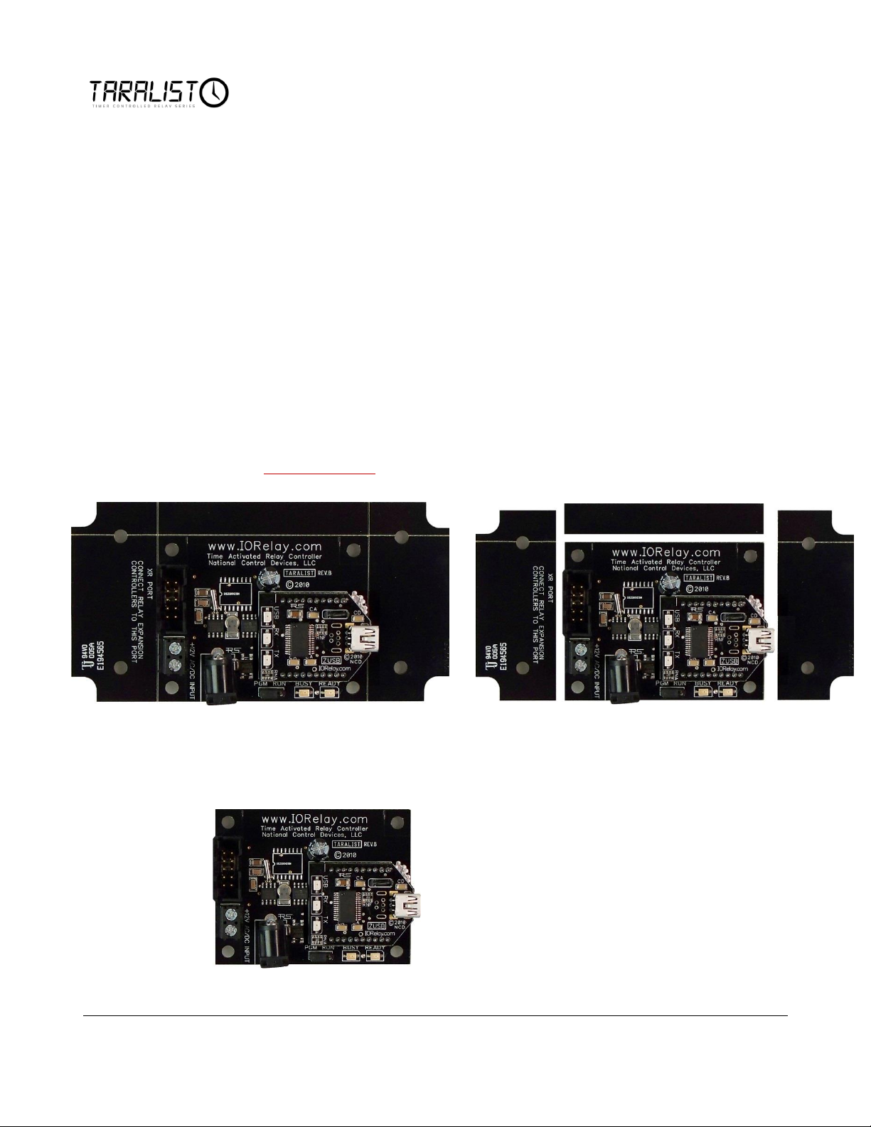
Taralist shown above as shipped from National
Control Devices. The shape accommodates a
standard enclosure.
Bend the Tables to break them away from the
board. Note that controllers with Broken Tabs are
NOT Returnable for Refund or Credit, but are still
covered under our Limited Warranty.
Break Away Tabs
Physically, most Taralist controllers are actually 2 sizes. When you receive your
Taralist controller, the shape and size ensures the controller can fit into a standard
enclosure. Optionally, you can make the controller smaller by breaking away the
outer tabs. Break-Away tabs are useful in applications where space may be a
concern. This allows your Taralist controller to offer the same functionality in the
smallest possible profile. Break-Away tabs are unique to the NCD product line
and are a standard option for most devices released in 2010 and later.
Before breaking the tabs on your controller, please be advised that your Taralist
controller will not be returnable for refund or credit if the Break-Away Tabs have
been removed.
To break away the tabs, gently but firmly grab each break-away tab with a pair of
pliers and bend the tab back and forth until it breaks away from the main circuit
board. This will NOT damage the controller in anyway.
Breaking the Tabs from a controller DOES NOT VOID the warranty. Please see
the NCD return policy if you would like more information on the policies that apply
to Surface Mount devices.
Shown here, the final controller with tabs removed is
physical smaller in size, but no longer fits a standard
enclosure.
7
Page 13
Chapter
3
E
Taralist Configuration
stablishing communications with a Taralist controller is an essential step in
using this device. Taralist Series controllers are available in many different
varieties. While all controllers are capable of functioning WITHOUT a computer,
a computer is REQUIRED to configure the Taralist controller.
The way the Taralist controller communicates with your computer depends on the
communication interface option you have chosen. If you choose an interface
other than USB, we strongly recommend that you also purchase a ZUSB
Communication module, which will allow you to revoke from communication loss
or error. Please refer to the appropriate Quick Start Guide for your
communication interface. The guides may be found on our website:
www.controlanything.com.
Your Taralist controller CANNOT be configured, and it will not be possible to
proceed through these instructions without knowing the current COM port
assignment. Please refer to the Quick Start Guide for your Interface to determine
this information.
Configuring Taralist with Base Station Software:
Download and install the latest version of NCD Base Station software by
following this link.
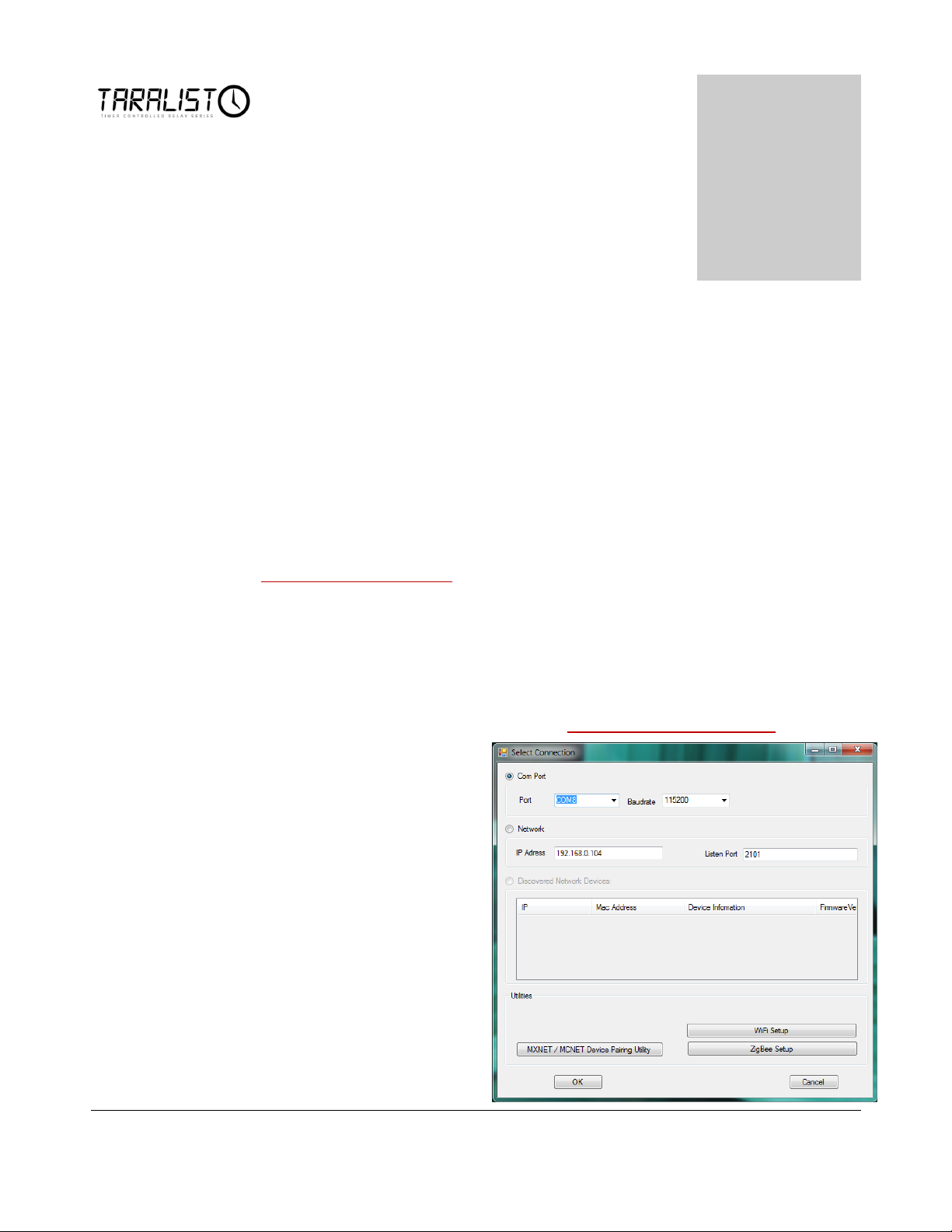
1. Run the NCD Base
Station software; you
should see the following
window appear.
2. Select the appropriate
Com Port for your
device from the ‘Select
Connection’ window and
click ‘OK’.
8
Page 14
Note: Some users may find the Taralist controller particularly suitable for a
specific application. Once you have created a Configuration file that matches
your needs, you may email your Taralist configuration file to us, and we can build
and ship any number of Taralist controllers with your configuration built in! This
will save you time and allow you to order a controller that is customized for your
exact application at no additional cost.
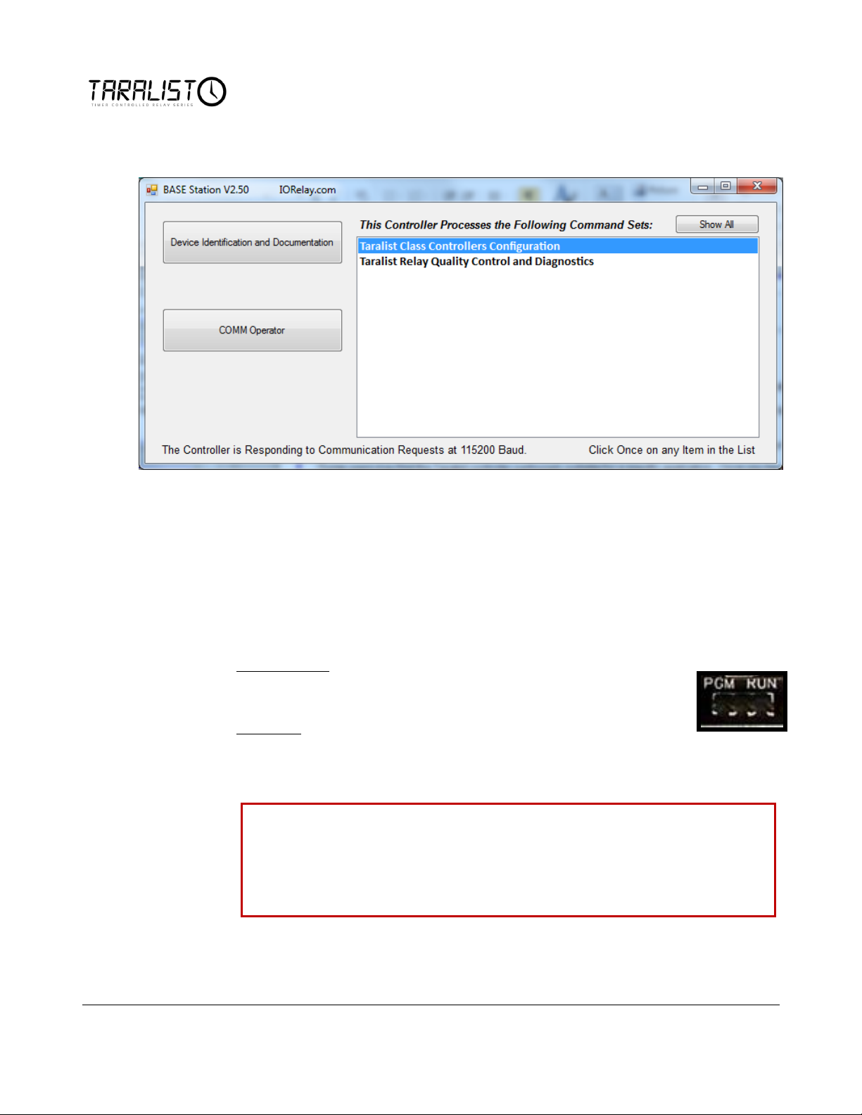
3. Click ‘Taralist Class Controller Configuration’ to begin configuring your
device as shown below.
The NCD Base Station software is a powerful program used to load and save
profiles into a Taralist controller.
Note: It is NOT possible to store Taralist configuration data into the Taralist
Controller when the Program/Run jumper (PGM/RUN) is set to the Run
position. This jumper may be changed at any time. Power cycling is NOT
REQUIRED.
Program Mode allows you to permanently write to onboard
nonvolatile storage. Use this mode to load, test, and modify Taralist
configuration data.
Run Mode write protects memory, making it impossible to store new
configuration settings.
9
Page 15
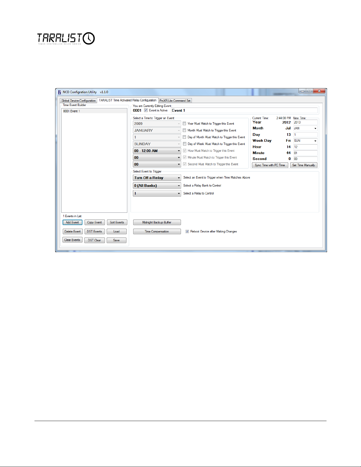
4. When communications is established, the current information from the
controller will be loaded. Then you will see the following screen appear. This
screen has three tabs across the top the allow you to configure and control
your Taralist device.
Now that communications are established between your computer and the
Taralist controller, we are ready to move onto configuring the device. To start,
there are a few things to understand when it comes to Taralist Logic. We will
start with Events.
10
Page 16

Understanding Events
Events are scheduled times when a relay or group of relays are turned on or off.
They are defined by the user by time: Year, Month, Day of Month, Day of week,
Hour, Minute, and Second. By having these options you have the ability of
switching relays on or off at very specific times. They are also defined by how
they control the relays, whether they turn a relay or group of relays on or off.
You can add up to 999 Events to the list.
First we will talk about defining the time of an Event. When determining time,
the hour, minute, and second are required information.. These parameters must be
entered. If only these parameters are filled, then he event will occur every single
day at this time. However, you can fill in the Day of Week box so the event only
occurs on a certain day of the week such as Monday. You must check the box
next Day of Week Much Match to Trigger Event for this parameter to take effect.
By filling in the rest of the parameters you can have an event only occur on
December 25 2012 at 1:53.45 PM on that exact second.
Secondly we will talk about what the Event does, it controls relays. You can select
exactly which relays in which banks (group of 8 relays) you want to come on or
turn off when the event is triggered.
11
Page 17
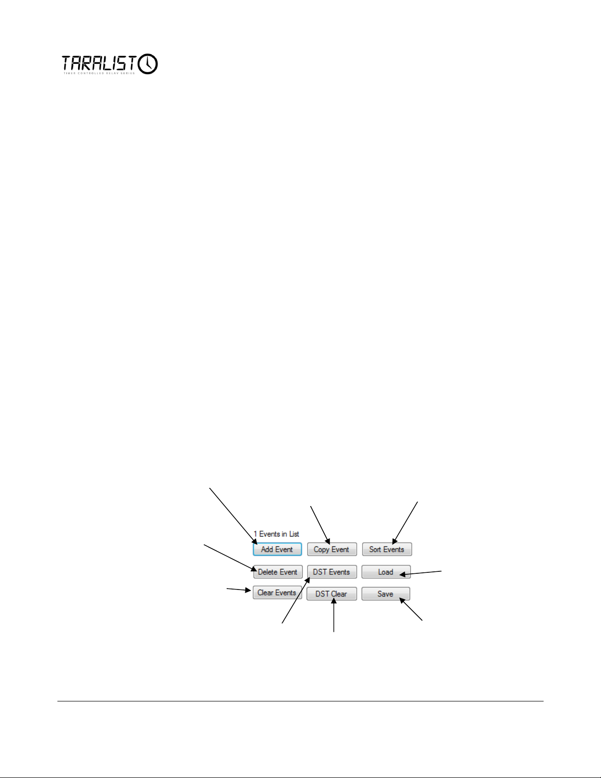
Delete Event will
Remove the event
from the list.
DST Clear will
remove all
Daylight Saving
time events.
Save will save
your current list
of events to a
file on your
computer.
Load will allow
you to load a
previously saved
Configuration
Sort Events will put
events in order by
time and Date. This
will be covered more
on a later page in
the manual.
Copy Event will make a
copy of the currently
highlighted Event in the list,
this is useful if you are
creating several similar
events that only need one or
two parameters changed.
Add Event will add a
new event to the list
which you can then
Clear Events will remove
all events from the list.
DST Events will add
Day Light Savings Time
Events where the
controller will reset its
clock to compensate for
Daylight Savings.
Adding/Removing Events
Events will be added under the ‘Time Event Builder’ on the left side of the
‘TARALIST Time Activated Relay Configuration’ tab.
1. Add Event: The first thing you will do is add an event. One an Event is added to the list; it may then be
edited with time and relay control information.
2. DST Events: Users have the option to automatically add all daylight savings time events to the event list.
When this button is pushed Daylight Saving time events are added to cover the next 30 years. This will
compensate the Taralist’s Clock each time Daylight Savings Time Comes Around. However, this may be
removed by simply clicking the DST Clear Button.
3. Save: Once you have spent the time to build a list of events we highly recommend you save that list of
events as it cannot be loaded from the controller, there simply is not enough room in its memory chip. By
clicking this button you will be prompted to save a file on your computer. At any time you can open this
file and load it into the controller quickly and simply.
4. Load: You may load an Event List, saved as a file on your computer, into your controller easily by
clicking this Loading button. If you need to load a previously saved List of Events, this is the way to do it.
5. Sort Events: Sort Events will put all of the events entered into the list in order by time and date. This is
very important to know. All 999 events are checked every second by the controller to look for a match
with a current time. If two events conflict with each other, the controller will not be able to process either
event properly. So if a relay does not come on when it is supposed to, click this ‘Sort Events’ button and
look for events that conflict with each other. It is important to know that items at the top of the list have
lowest priority while items at the bottom of the list have the highest priority. We recommend sorting your
list periodically when entering events to the list. The Taralist controller scans through all events in the list
from top down to the bottom so events at the end of the list may override events at the top of the list.
12
Page 18
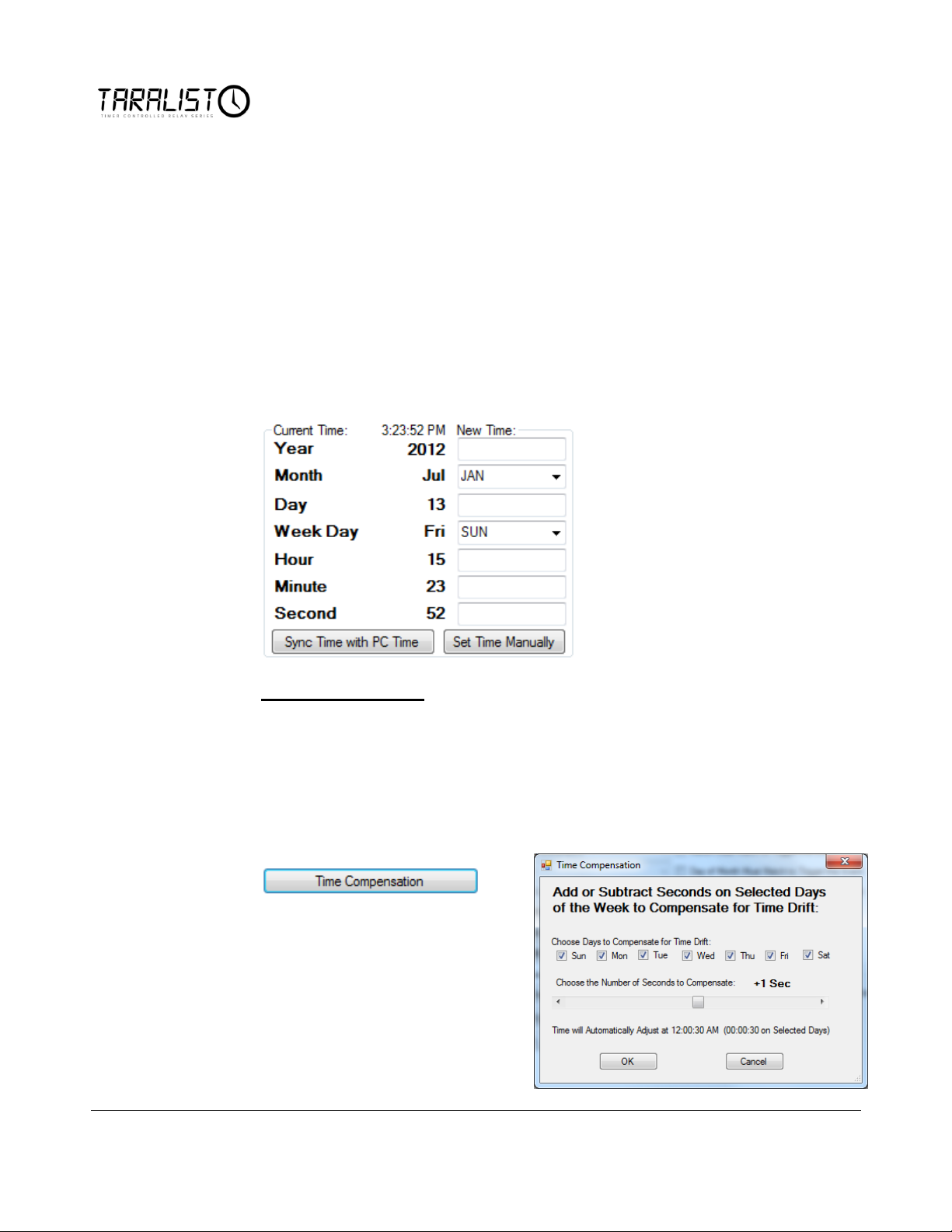
Defining Time
Now that we have determined what an event is and how to define an event, we
can move on to how the Taralist controller keeps track of time. By default the
Taralist controller does not know what time it is so this must be defined. The
only way of doing this is from the NCD Base Station software. Once your
controller is connected to the computer and the program is launched, the first
thing to do is tell the Taralist Controller what time it is. You may do this manually
or you can Sync the time with your PC. The settings for this are located on the
right side of the ‘TARALIST Time Activated Relay Configuration’ tab. The user
can do this by simply clicking the Sync Time with PC Time button or by filling in
the Year, Month, Day, Week Day, Hour, Minute, Second parameters and then
clicking the Set Time Manually button.
Time Compensation
Another feature that must be noted is that the Taralist controller’s time may drift
by as much as a second each day. How much the controller drifts is determined
by Temperature, Power Supply, and specific application differences. This has
been accounted for in the design of the Taralist Controller and NCD Base Station
software using the ‘Time Compensation’ feature found on the ‘TARALIST Time
Activated Relay Configuration’ tab. Once this Button is clicked, a new window
will open.
Using this Feature, the user can add
or subtract a specified amount of
seconds in the Taralist Clock each
day or only on a certain day to
compensate for time drift in the
Taralist Controller.
13
Page 19
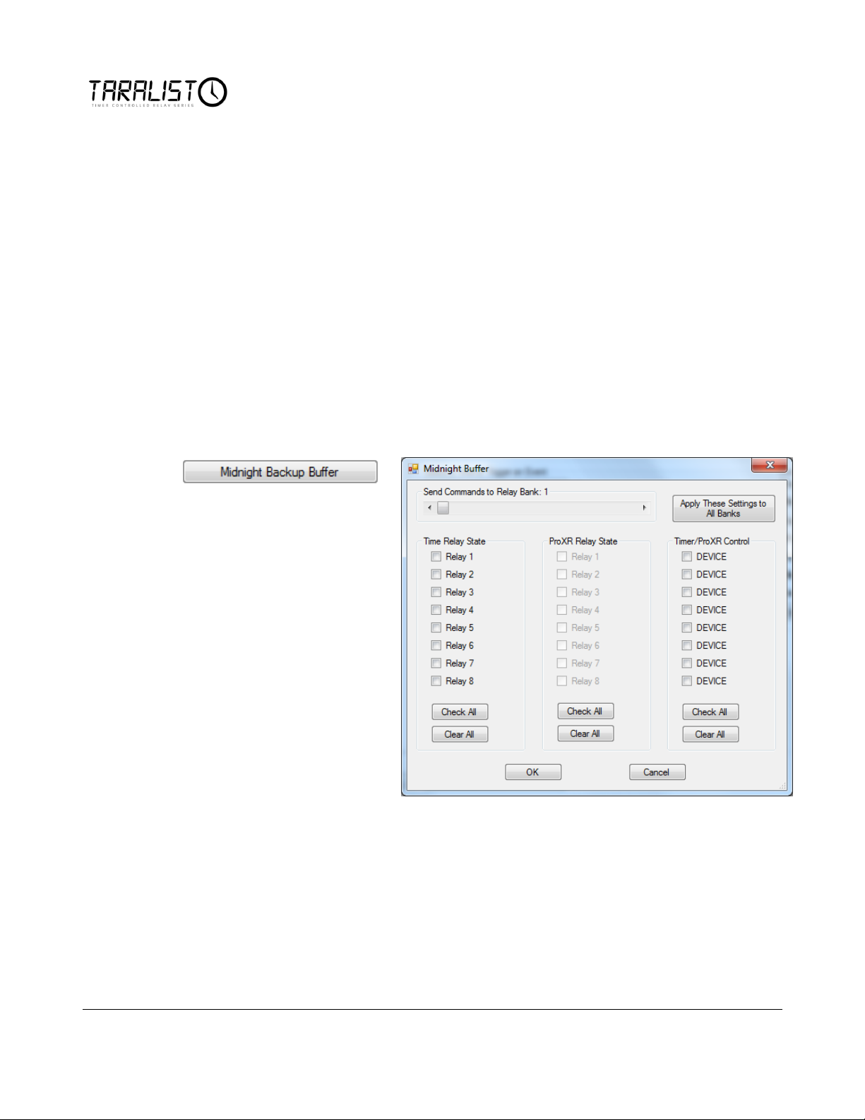
Midnight Backup Buffer
The Midnight Backup Buffer is absolutely essential to the functionality of the
Taralist controller. Without it power loss would result in a useless device.
Constant power supply is recommended for all Taralist controllers and a UPS style
battery backup system is also recommended. However, no matter how many
precautions are taken, at some point a Taralist controller will lose power. For
example, if a relay is turned on a by an event on Monday and is told to turn back
off on Friday but power is lost on Wednesday, without the Midnight Backup
Buffer the relay will not turn back on until the following Monday. So now you
can see how essential this feature is.
Every night at Midnight; 0 hours, 0 minutes, 0 seconds, the controller reads what
the status of all relays are at the exact second and stores that information into the
Midnight Backup Buffer. If a controller loses power momentarily and is powered
back up, it will scan through all events from Midnight to the exact moment it is
powered up. It will also take into account the status of all relays at Midnight to
determine what the status of all relays should be at the current time.
You can read the status of the Midnight Backup Buffer at any time by clocking the
‘Midnight Backup Buffer’ button found on the ‘TARALIST Time Activated Relay
Configuration’ tab. You may also modify the status of the Midnight Backup
Buffer stored inside the Taralist controller. This is helpful if you are working with
brand new controller and it has nothing stored in the Midnight Backup Buffer. If
the relay was supposed to be turned on Monday and turned off Friday but you got
your controller on Wednesday, you can modify the Midnight Backup Buffer to
think the Relay was on at Midnight and if no events during the day tell it to turn
off until Friday, the relay will come on until Friday. Otherwise the Relay would
not come on until Monday next week.
14
Page 20
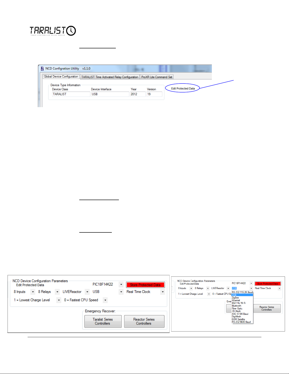
Click ‘Edit
Protected Data’ to
receive
options.
Protected Data
The ‘Global Device Configuration’ tab is used to reboot the controller or edit
protected data.
Editing Protected Data
Protected Data is best described as a form of BIOS for a Taralist controller.
Under most circumstances, it is not necessary to Edit Protected Data, but there
are circumstances that may require this operation. Protected Data holds
important parameters regarding the Taralist Relay controller you are using. In
some cases, you may want to change your hardware, so Editing Protected Data
may be essential.
additional
A Taralist Controller is allowed to interface to a computer while Runtime Mode.
The ‘Edit Protected Data’ feature is a universal resource for several different types
of controllers that National Control Device offers. For this reason there are
options under Edit Protected Data that do not apply to Taralist controllers.
Device Interface
One option that could be changed under Edit Protected Data is the computer to
device interface drop down menu shown above. You will be able to choose from
USB, 802.15.4, ZB Mesh, etc.
Charge Level
Another option that may be changed with your Taralist controller is the Charge
Level. This will control how fast the Taralist charges its onboard battery backup.
We recommend leaving the charge level as low as possible, 1 preferably, in order
to extend the life of the battery.
Other options such as number of inputs, number of relays, CPU Speed, Type of
Device, and IC number do not apply to your Taralist controller.
15
Page 21
Computer Control of Taralist
Computer Override
The Taralist series controllers have some amazing abilities when it comes to
making decisions on their own based on the events you configure into them, but
you can take control of the relays at any time from a computer as long as
communications are established between your computer and the Taralist device.
The Taralist Series Relay controllers support a “Lite” ProXR command set. If you
are familiar with our ProXR series relay controllers, then the command set should
be easy to understand. We will provide a summary of all Taralist commands in
this manual, but for now, let’s explore some of the computer control features.
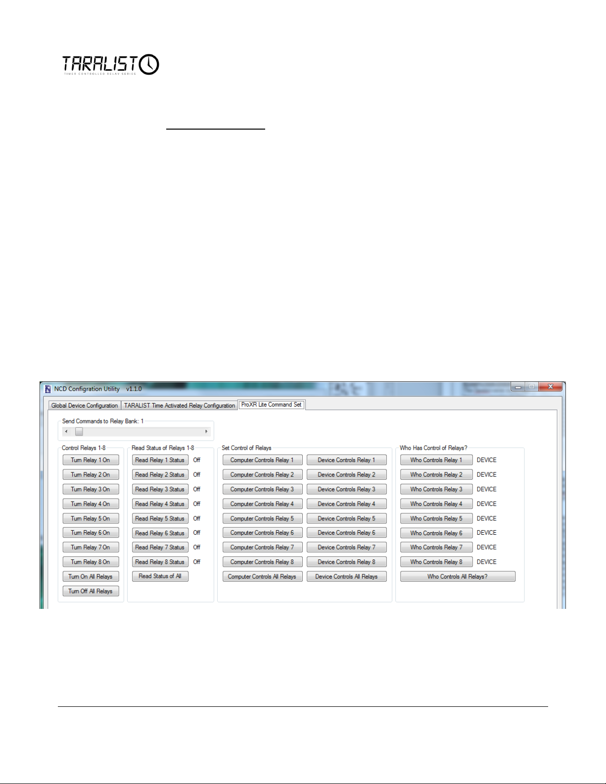
Interface Elements
The interface elements shown below allow a computer to take over control of any
relay and force the relays to a On or Off state. You may also turn all relays on or
off using the ‘Turn On All Relays’ and ‘Turn Off All Relays’ buttons.
You can also read the status of relays by clicking the ‘Read Relays 1-8 Status’. The
Status of the relay will be shown to the right of the button.
The slider at the top of the screen allows you to select which bank of relays these
commands are directed to. You may attach up to 32 banks or 256 Relays.
16
Page 22

Set Control of Relays
When you change the state of a relay manually from this screen, you have taken
control of the particular relay and the Taralist controller will not be able to control
it. Using the ‘Set Control of Relays’ in the center section above, set the relay to be
controlled by the Computer or the Taralist Device. It is important to always
return control of the relay back to the Taralist device after you are done manually
controlling it.
Who Has Control of the Relays?
It is important to know if the Taralist device or your computer has control of the
relays. Use the ‘Who Has Control of Relays?’ section on the right to read who has
control of each individual relay. Simply click the ‘Who Controls Relay 1’ button
and the information will be updated to the right of the button telling you who has
control of Relay 1. You may also read who has control of all 8 relays in a bank by
clicking the ‘Who Controls All Relays’ button.
Custom Software Control
Custom software may be written to take computer control of the relays by using
the ProXR Lite Command Set. Custom Software may be written on any software
platform capable of sending RS 232 bytes of data through a Com Port or through
direct TCP/IP communications for Ethernet Devices.
17
Page 23

Chapter
4
Command Set
The following commands may be sent to the Reactor Series Relay Controllers to
take control of relays and process other functions and inquiries. Commands may
be sent in Decimal values or Decimal Values may be converted to Hex depending
on the preferred format of your programming language.
Please follow these steps to properly communicate to a Reactor:
1. Clear Serial Receive Buffer (VERY IMPORTANT)
2. Send Command
3. Wait for a Response
Baud Rate is typically 115.2K Baud, 8 Data Bits, 1 Stop Bit, No Parity.
Baud Rate is 57.6K Baud for XSC Devices
Baud Rate can be set to 9600 Baud for RS-232 Version
IMPORTANT: Taralist firmware has been re-written. If your controller is
identified as a ‘Taralist Enhanced’ Base Station Software, then your controller is
capable of accepting commands at high communications speeds. Older versions
of the firmware will require a 1ms delay between communication bytes. NCD
STRONGLY ENCOURGES A FIRMWARE UPGRADE IF YOU ARE NOT
USING TATLIST ENHANCED FIRMWARE.
18
Page 24

Example to Activate Relay 1:
1. Clear Serial Receive Buffer
2. Send Byte 254 (Hex 0xFE)
3. Wait 1ms (Original Taralist firmware ONLY, Skip this Step if using Taralist
Enhanced)
4. Send Byte 108 (Hex 0x6C)
5. Wait 1ms (Original Taralist firmware ONLY, Skip this Step if using Taralist
Enhanced)
6. Send Byte 1 (Hex 0x01)
7. Wait for Response Byte 85 (Hex 0x55)
Send Bytes: Byte 1: Byte 2: Byte 3:
Function: Header Command Code Parameter
Decimal Values: 254 108 1
Hex Values: 0xFE 0x6C 0x01
Receive Byte: Decimal: 85
Hex: 0x55
19
Page 25
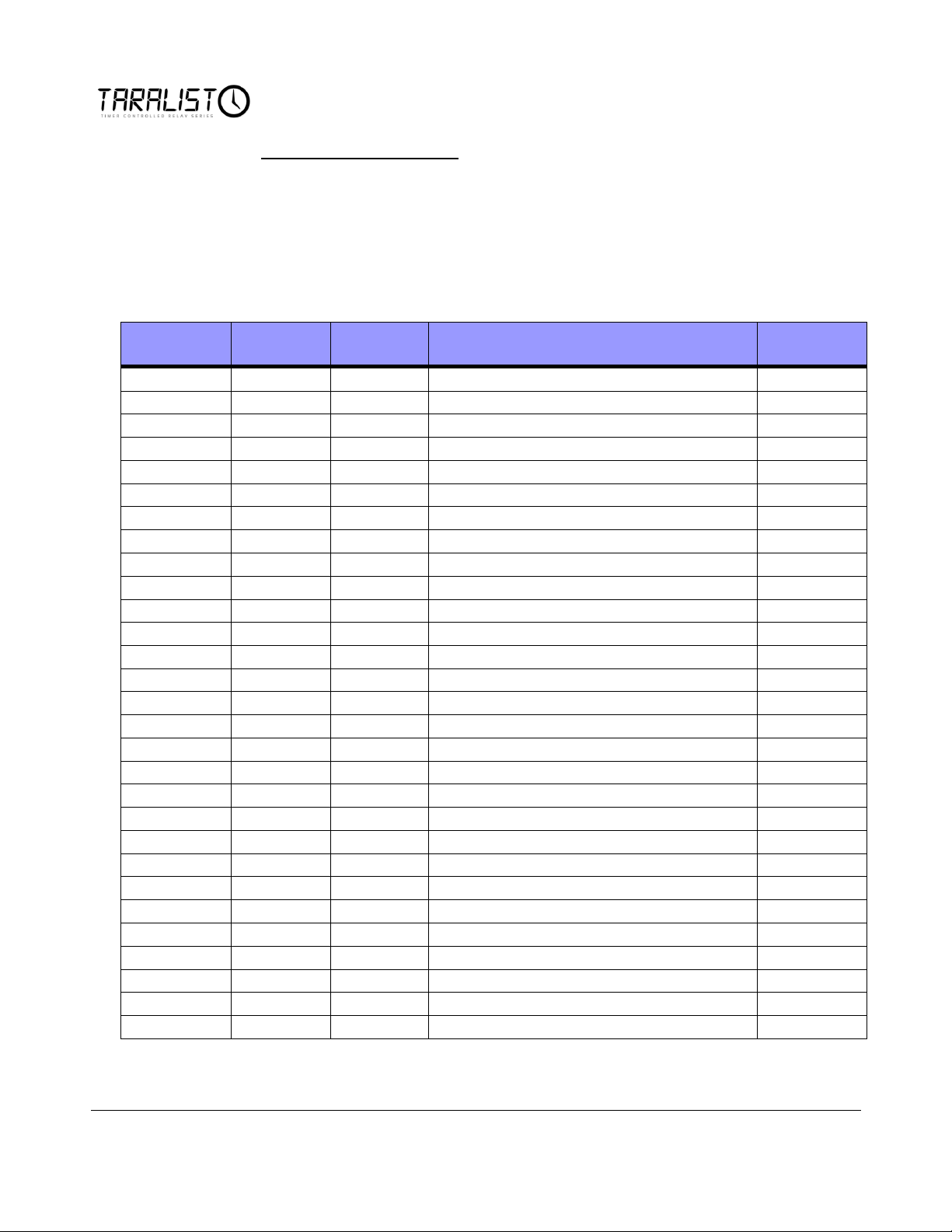
Header Byte
Command
Code
Parameter
Description
Return Byte
254
33
Test 2-Way Communication
85
254
100
Bank
Turn Off Relay 1 in Selected Bank
85
254
101
Bank
Turn Off Relay 2 in Selected Bank
85
254
102
Bank
Turn Off Relay 3 in Selected Bank
85
254
103
Bank
Turn Off Relay 4 in Selected Bank
85
254
104
Bank
Turn Off Relay 5 in Selected Bank
85
254
105
Bank
Turn Off Relay 6 in Selected Bank
85
254
106
Bank
Turn Off Relay 7 in Selected Bank
85
254
107
Bank
Turn Off Relay 8 in Selected Bank
85
254
108
Bank
Turn On Relay 1 in Selected Bank
85
254
109
Bank
Turn On Relay 2 in Selected Bank
85
254
110
Bank
Turn On Relay 3 in Selected Bank
85
254
111
Bank
Turn On Relay 4 in Selected Bank
85
254
112
Bank
Turn On Relay 5 in Selected Bank
85
254
113
Bank
Turn On Relay 6 in Selected Bank
85
254
114
Bank
Turn On Relay 7 in Selected Bank
85
254
115
Bank
Turn On Relay 8 in Selected Bank
85
254
116
Bank
Read Status of Relay 1 in Selected Bank
0-1
254
117
Bank
Read Status of Relay 2 in Selected Bank
0-1
254
118
Bank
Read Status of Relay 3 in Selected Bank
0-1
254
119
Bank
Read Status of Relay 4 in Selected Bank
0-1
254
120
Bank
Read Status of Relay 5 in Selected Bank
0-1
254
121
Bank
Read Status of Relay 6 in Selected Bank
0-1
254
122
Bank
Read Status of Relay 7 in Selected Bank
0-1
254
123
Bank
Read Status of Relay 8 in Selected Bank
0-1
254
124
Bank
Report Status of Selected Relay Bank
0-255
254
129
Bank
Turn Off all Relays in Selected Bank
85
254
130
Bank
Turn On all Relays in Selected Bank
85
254
140
Bank
Set the Status of All Relays in Selected Bank
85
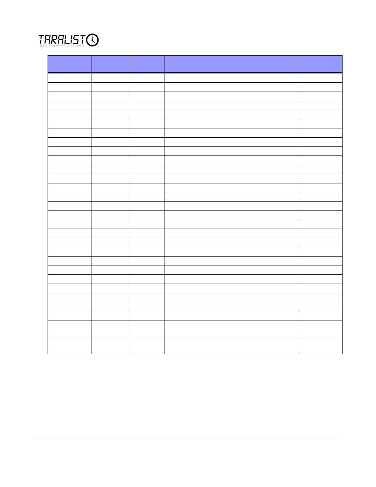
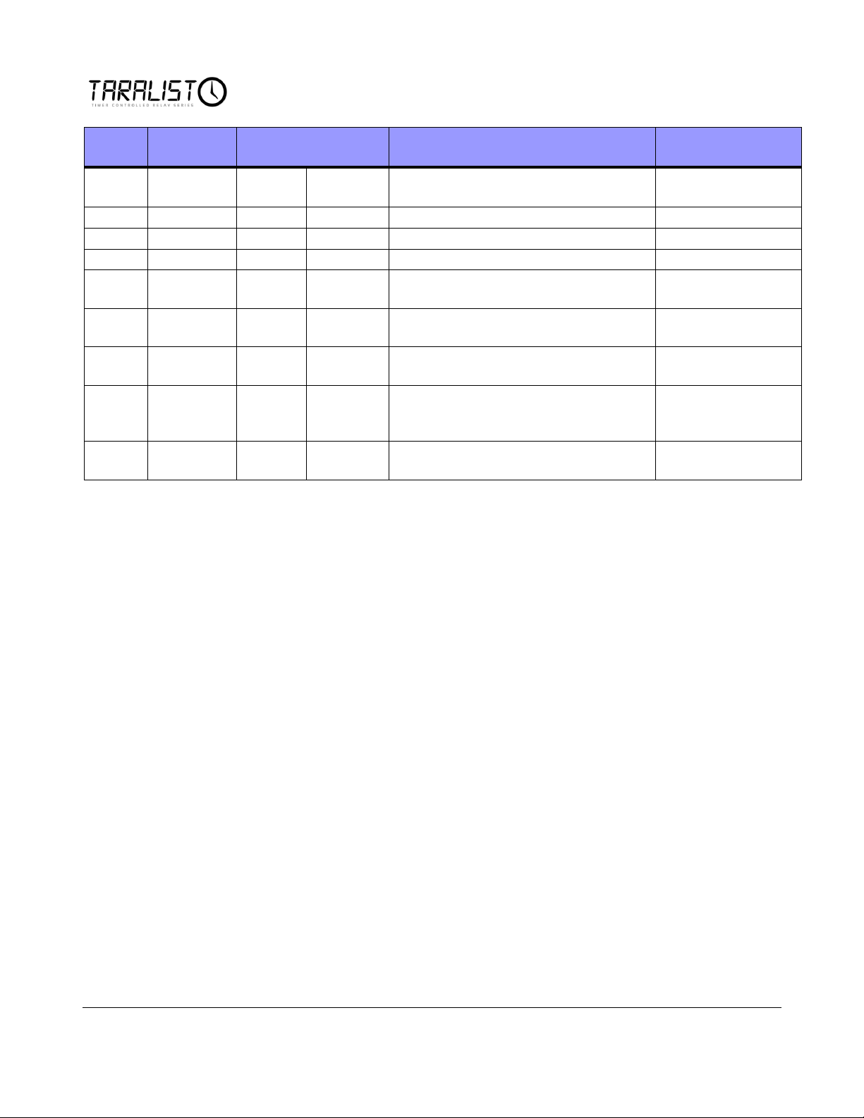
Command Set Summary
The following commands may be sent to the Reactor Series Relay Controllers to
take control of relays and process other functions and inquiries. Commands may
be sent in Decimal values (as shown) or may be converted to Hex depending on
the preferred format of your programming language. The Left column indicates
the header byte; the second column indicates the command code. A parameter (if
required) is shown in third column. A description indicates the function of the
command, and finally return bytes are shown.
20
Page 26
Header Byte
Command
Code
Parameter
Description
Return Byte
254
246
Get Device ID Data
4-Bytes
64
246
Reboot Controller
No Return
64
100
Bank
Set Control of Relay 1 to Device
85
64
101
Bank
Set Control of Relay 2 to Device
85
64
102
Bank
Set Control of Relay 3 to Device
85
64
103
Bank
Set Control of Relay 4 to Device
85
64
104
Bank
Set Control of Relay 5 to Device
85
64
105
Bank
Set Control of Relay 6 to Device
85
64
106
Bank
Set Control of Relay 7 to Device
85
64
107
Bank
Set Control of Relay 8 to Device
85
64
108
Bank
Set Control of Relay 1 to Computer
85
64
109
Bank
Set Control of Relay 2 to Computer
85
64
110
Bank
Set Control of Relay 3 to Computer
85
64
111
Bank
Set Control of Relay 4 to Computer
85
64
112
Bank
Set Control of Relay 5 to Computer
85
64
113
Bank
Set Control of Relay 6 to Computer
85
64
114
Bank
Set Control of Relay 7 to Computer
85
64
115
Bank
Set Control of Relay 8 to Computer
85
64
116
Bank
Read Control Status of Relay 1 in Selected Bank
0-1
64
117
Bank
Read Control Status of Relay 2 in Selected Bank
0-1
64
118
Bank
Read Control Status of Relay 3 in Selected Bank
0-1
64
119
Bank
Read Control Status of Relay 4 in Selected Bank
0-1
64
120
Bank
Read Control Status of Relay 5 in Selected Bank
0-1
64
121
Bank
Read Control Status of Relay 6 in Selected Bank
0-1
64
122
Bank
Read Control Status of Relay 7 in Selected Bank
0-1
64
123
Bank
Read Control Status of Relay 8 in Selected Bank
0-1
64
124
Bank
Report Control Status of Selected Relay Bank
0-255
64
129
Bank
Set all Relays Under Device Control Relays in
Selected Bank
85
64
130
Bank
Set all Relays Under Computer Control Relays in
Selected Bank
85
21
Page 27
Header
Byte
Command
Code
Parameter
Description
Return Byte
64
140
Status
Bank
Set the Control Status of All Relays in
Selected Bank
85
65
246
Halt Event Processing
85
65
247
Resume Event Processing
85
65
99
Get Current Time from Controller
7 Bytes + Checksum
65
100
7 time
Bytes
Plus
Checksum
Set Current Time from Controller
85 Successful
86 Error
0 1
Load Data from CPU EEPROM for Use
by Configuration Utility Only
0 2
Save Data to CPU EEPROM for Use by
Configuration Utility ONLY
0 3
Load Data from External EEPROM
Chip for Use by Configuration Utility
ONLY
0 4
Save Data to External EEPROM Chip
for Use by Configuration Utility Only
22
Page 28
Chapter
5
Relay Logic
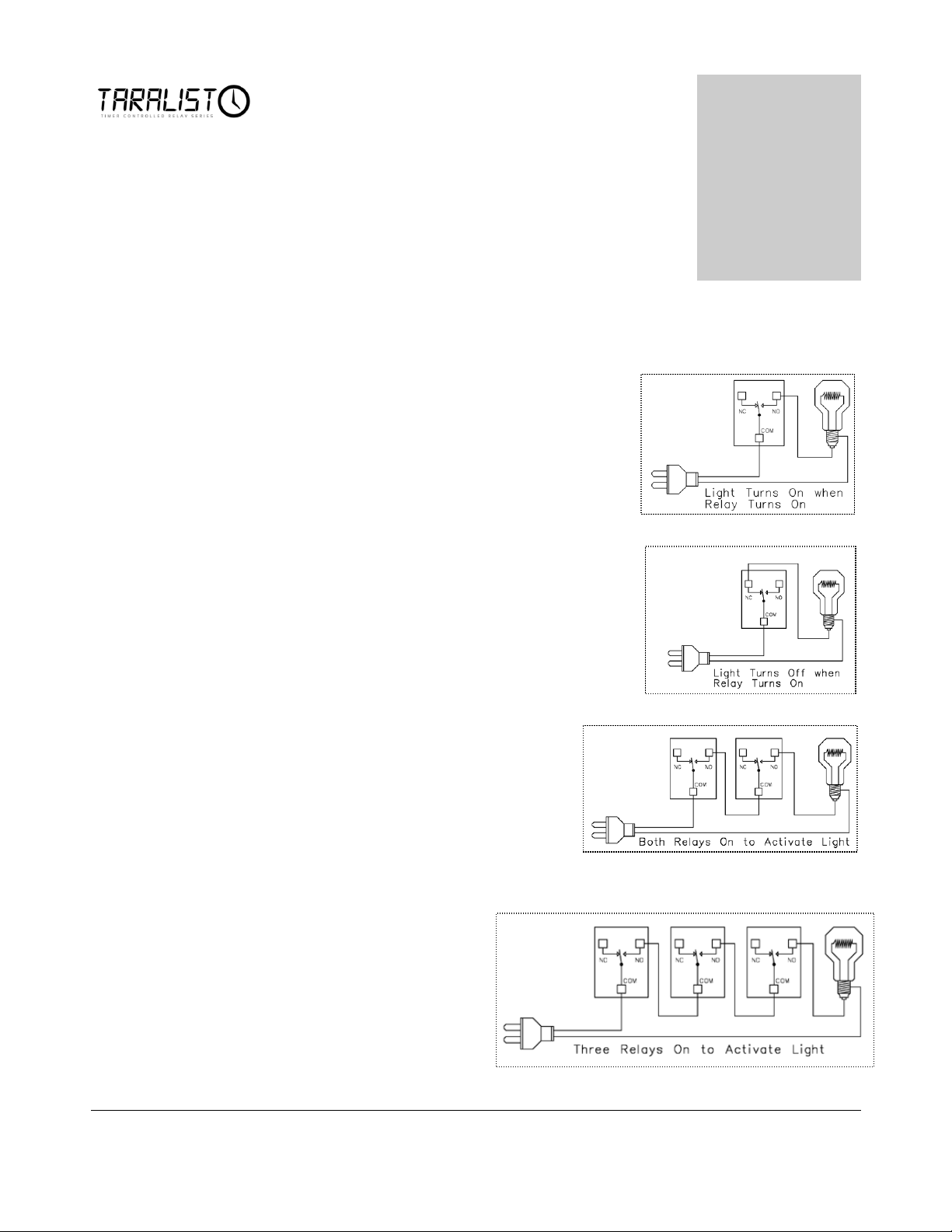
Sample 1
This sample demonstrates how a relay can be used
to activate a light bulb. When the relay turns on,
the light comes on. Only one power wire is
switched with this sample using the COM
(common) and NO (normally open) connections of
the relay.
Sample 2
This sample demonstrates how a relay can be used
to turn a light bulb OFF. When the relay turns off,
the light will be ON. Only one power wire is
switched in this sample using the COM (common)
and NC (normally closed) connections of a relay.
Sample 3
This sample demonstrates how three
activated lights are required to activate a
light bulb. This is the same as a Logic
AND function because Relay 1 AND Relay
2 AND Relay 3 MUST be on to activate
the light.
Sample 4
This sample demonstrates how
three activated lights are
required to activate a light bulb.
This is the same as a Logic
AND function because Relay 1
AND Relay 2 AND Relay 3
MUST be on to activate the
light.
23
Page 29
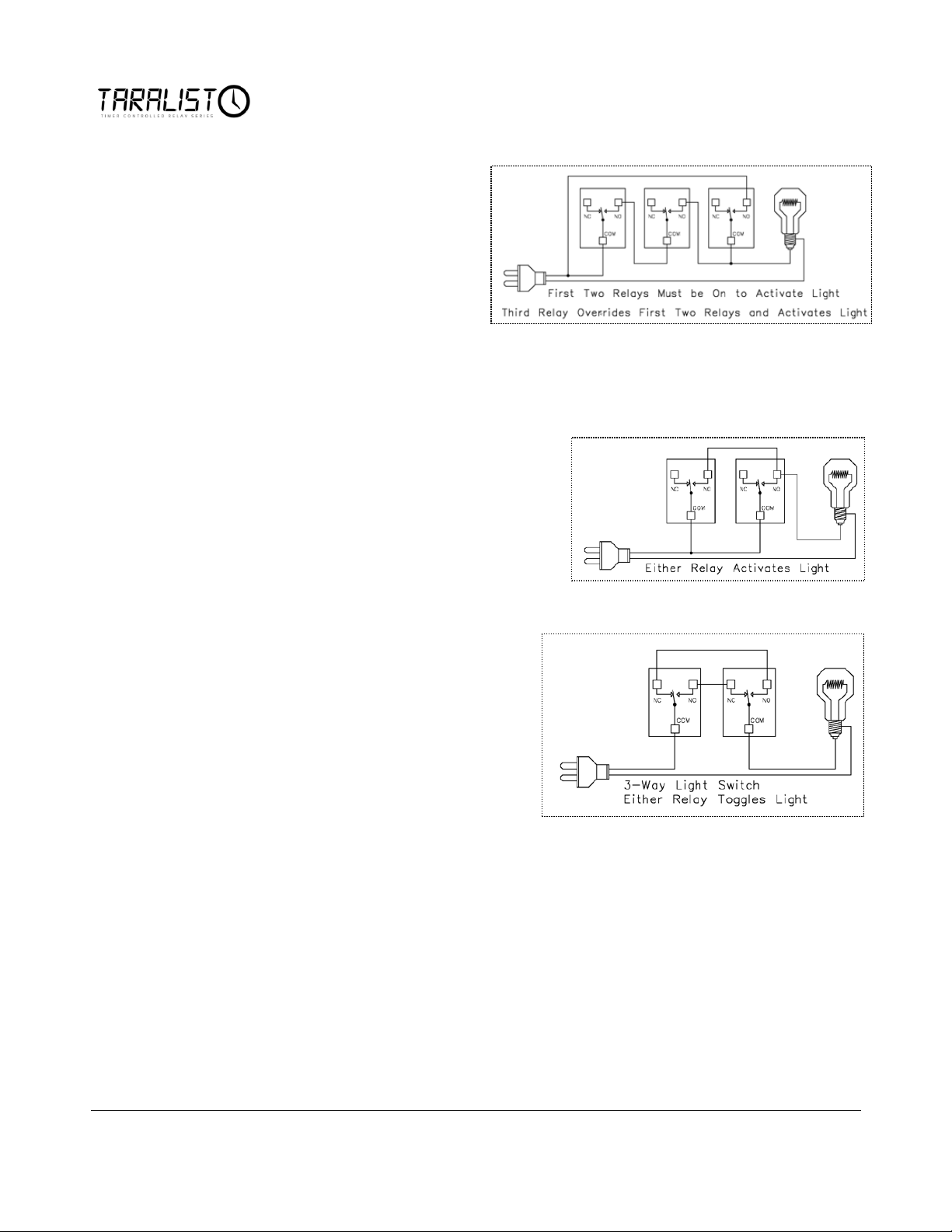
Sample 5
This sample demonstrates the
AND/OR function. The
Light Bulb will be activated if
Relay 1 AND Relay 2 are ON
OR if Relay 3 is ON. This
sample is perfect for
applications that may require a
Logical condition of 2 relays
PLUS an Override feature. For instance: Relay 1 is a Night/Day Sensor, Relay 2
is a Moisture Sensor. If it’s Dark AND the soil is Dry, Relays 1 and 2 can activate
a Pump. If you want to override these conditions with a Key Fob, Relay 3 may be
used.
Sample 6
This sample demonstrates how either
relay can be used to activate a light. In
this sample, only one activated relay is
required to activate the light. If both
relays are activated, the light will be on.
Sample 7
This sample demonstrates how a 3way light switch can be used to
activate a light. A 3-way light switch
is often found in your house where
two light switches can be used to
activate a single light. This sample is
exactly the same as a 3-way light
switch, the only difference being each
physical switch is replaced by a relay.
Operationally, it works the say way. Each relay activation will cause the light to
toggle. Switching two relays at one time is like flipping 2 switches at once…with
the same result. This sample is particularly useful since you can replace one relay
(as shown in the diagram) with a physical light switch. This will allow a
computer/Taralist to control a light as well as manual operation of a light.
Properly used, this can be one of the most valuable diagrams we offer on this
page.
24
Page 30
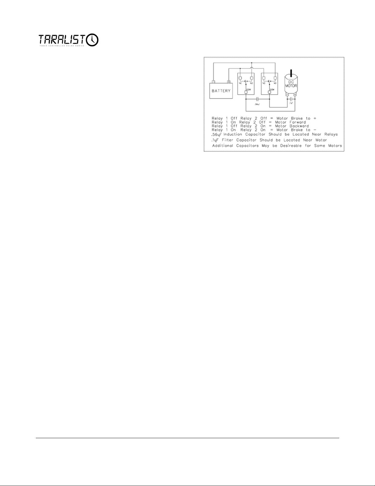
Sample 8
This sample demonstrates how to
control the direction of a DC
motor using 2 relays. Braking is
accomplished by connecting both
motor terminals to a common
power connection (Faraday’s
Law). The capacitors shown may
not be required for small motors,
but if you experience problems
with relays shutting themselves
off, the inductions suppression
capacitor will be required. The .1uF capacitor helps suppress electronic noise if
the battery were to be used by sensitive devices (such as radios/amplifiers).
25
Page 31
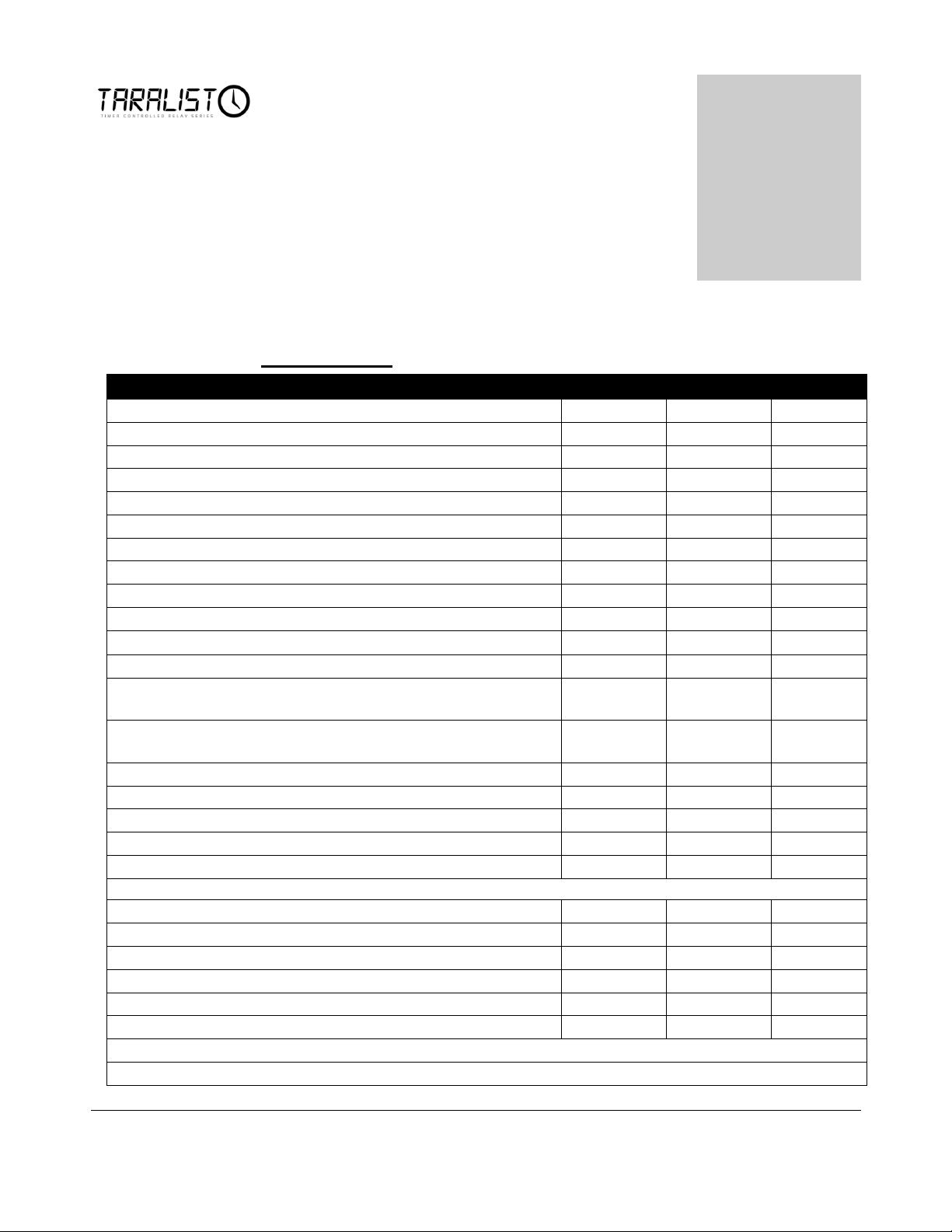
Absolute Maximum Ratings
Minimum
Rated
MAX
Input Voltage Requirements VDC
11
12
14.5
Amperage Requirements
Standby (No Relays On, No Communications Module
31ma
ZUSB USB Communications Module Installed
33ma
XBee 1mw Communications Module Installed
32ma*
XBee 100mw Communications Module Installed
32ma*
Each 5A/10A Relay Activated Adds to Consumption
32ma
Each 20A/30A Relay Activated Adds to Consumption
45ma
Each Solid State Relay Activated Adds to Consumption
5ma
Temperature Ratings (Estimated)**
-25°C
80°C
Mechanical Relay Cycle Life (Non-DPDT Versions):
>10,000,000
Cycles
Mechanical Relay Cycle Life (DPDT Versions):
>2,000,000
Cycles
Typical Operational Cycles per Minute:
1,800
Relay Activation Time:
>5ms
<15ms
Relay Deactivation Time:
>5ms
<20ms
Command Processing Time:
1ms
3ms
5ms
Relay Electrical Limits should be Determined by Reviewing Appropriate Relay Data Sheet:
5A Relays Data Sheet
10A Relays Data Sheet
20A Relays Data Sheet
30A Relays Data Sheet
Solid State Relays Sheet
* Communications will Increase Current Consumption by up to 250ms for short times.
** Ratings Based on Data Sheets of Component Used, Actual Tolerance May Exceed Ratings.
Chapter
6
Electrical Specifications
Maximum Rating
26
Page 32
Chapter
7
Troubleshooting
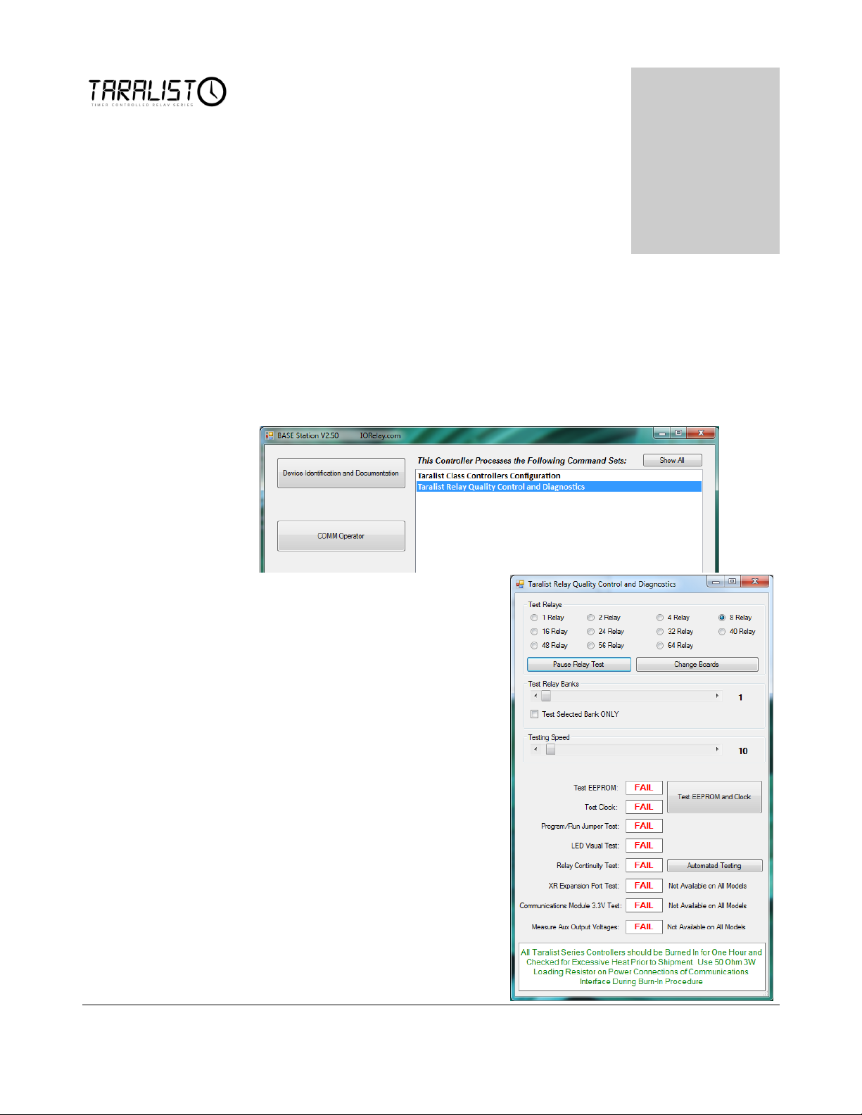
Base Station Software can be used to Test you device.
Run Base Station software
Choose the appropriate Com Port and click ‘OK’.
Click on ‘Taralist Relay Quality Control and Diagnostics’ to start testing
your device.
Test your controller with the
items on the Taralist Relay
Quality Control and Diagnostics
window.
27
Page 33

Problem: Relay does not come on at appropriate time.
Solution: Check that there are no conflicting events in the configuration. Click
the sort Events button as documented on page 10. It is important to know that
events at the top of the list have lowest priority. The reason for this is the Taralist
controller scans through all events in the list from the top to the bottom before it
refreshes the relays, so events at the bottom of the list can override events at the
top of the list.
An Inductive device can also cause communication malfunctions in the CPU,
review our Documentation on Inductive Devices to correct this problem.
Problem: Clock Speed running slow or fast.
Solution: The Taralist controller may be affected by temperature. In excessively
cold environments the clock may run slow, in excessively hot conditions the clock
may run fast. This can be corrected using the Time Compensation feature
documented on page 11. The Taralist controllers clock may naturally drift event at
room temperature by as much as 1 second per day. This can be corrected using
the Time Compensation feature.
Problem: Controller is Running HOT.
Solution: It is normal for some components run very hot on the Taralist series
relay controllers. This is not a concern as we have tested the design carefully and
are operating our components well within the specified limits of the components
we are using. It is NOT normal for the CPU to run hot at any time. The CPU
should remain cool. If the CPU is running hot and/or both Busy/Ready LEDS
are on at the same time, the CPU has been damaged.
Problem: Unable to Communicate with Controller
Solution: Use the ZUSB Communication Module to validate communications; do
NOT use any other communications module if this error occurs. The ZUSB is
the safest communication method of all communication technologies, and must be
used if you experience configuration problems. Make sure you are using the
correct COM port. Our software has been tested under Windows XP, Vista, and
Windows 7. Windows XP Users MUST use .NET Framework 3.5 or Later with
all the latest service packs installed. If the problem persists, makes sure the serial
port is NOT in use by another application. Lastly, we can only recommend trying
a different computer if problems persist.
28
Page 34
Chapter
8
T
Technical Support
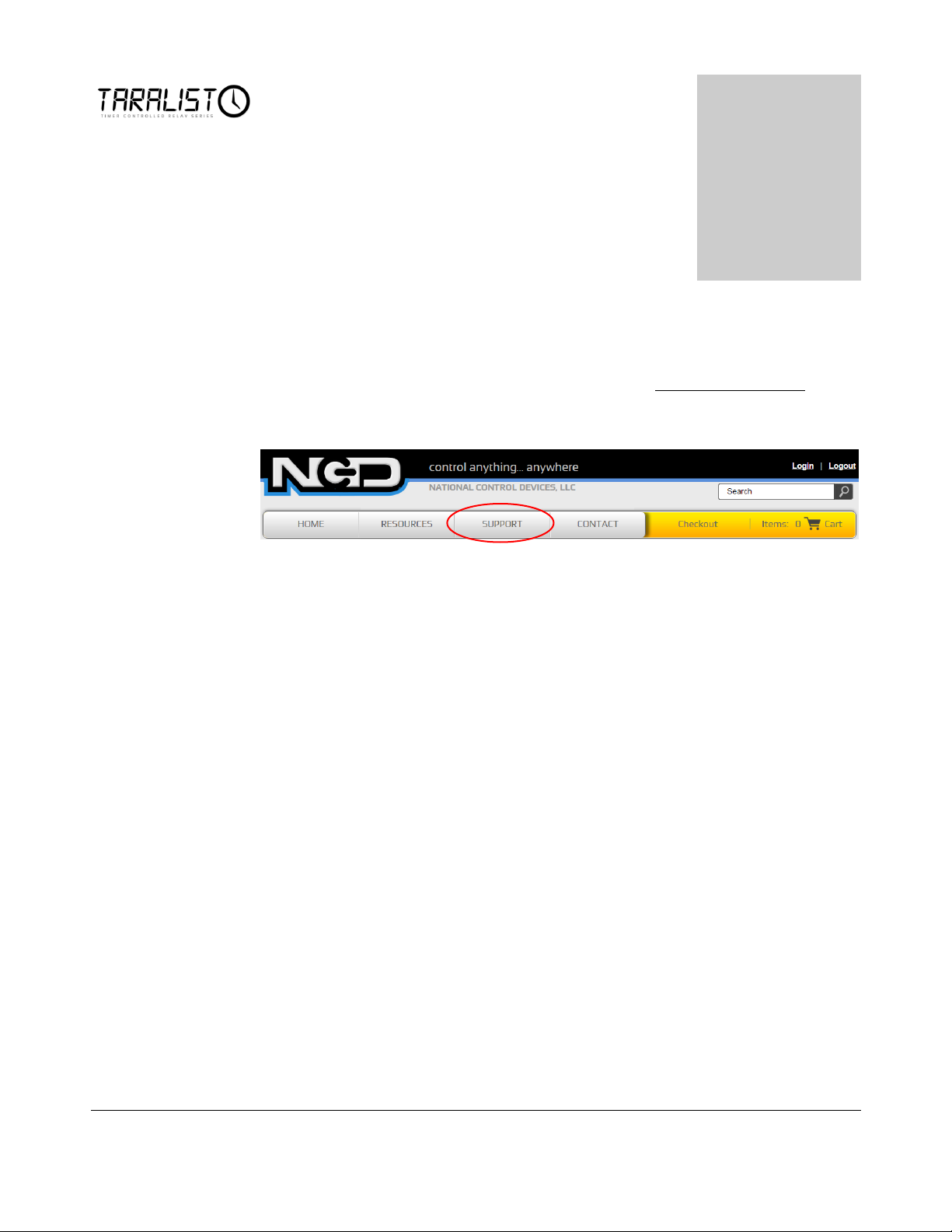
echnical support is available through our website, controlanything.com.
Support is the way we connect NCD engineers to our customers.
Click on the Support tab at the top of any page on our website to be
taken to the Forum page. Here you can publicly post or review problems
that customers have had, and learn about our recommended solutions.
Our engineers monitor questions and respond continually throughout the day.
Before requesting telephone technical support, we ask that customers please try to
resolve their problems through Support first. However, for persistent problems,
NCD technical support engineers will schedule a phone consultation.
29
Page 35

Contact Information
National Control Devices, LLC
PO Box 455
Osceola, MO 64776
417-646-5644 phone
866-562-0406 fax
Open 9 a.m. - 4 p.m. CST
Like “National Control Devices” on Facebook, and follow us on Twitter
@ControlAnything.
All orders must be placed online at our website, www.controlanything.com
Notice:
The only authorized resellers of NCD products are
www.controlanything.com
www.relaycontrollers.com
www.relaypros.com
All other websites are not authorized dealers; we have noticed some retailers
offering our products fraudulently.
Copyright © 2013
National Control Devices
All Rights Reserved.
30
 Loading...