

Page 1
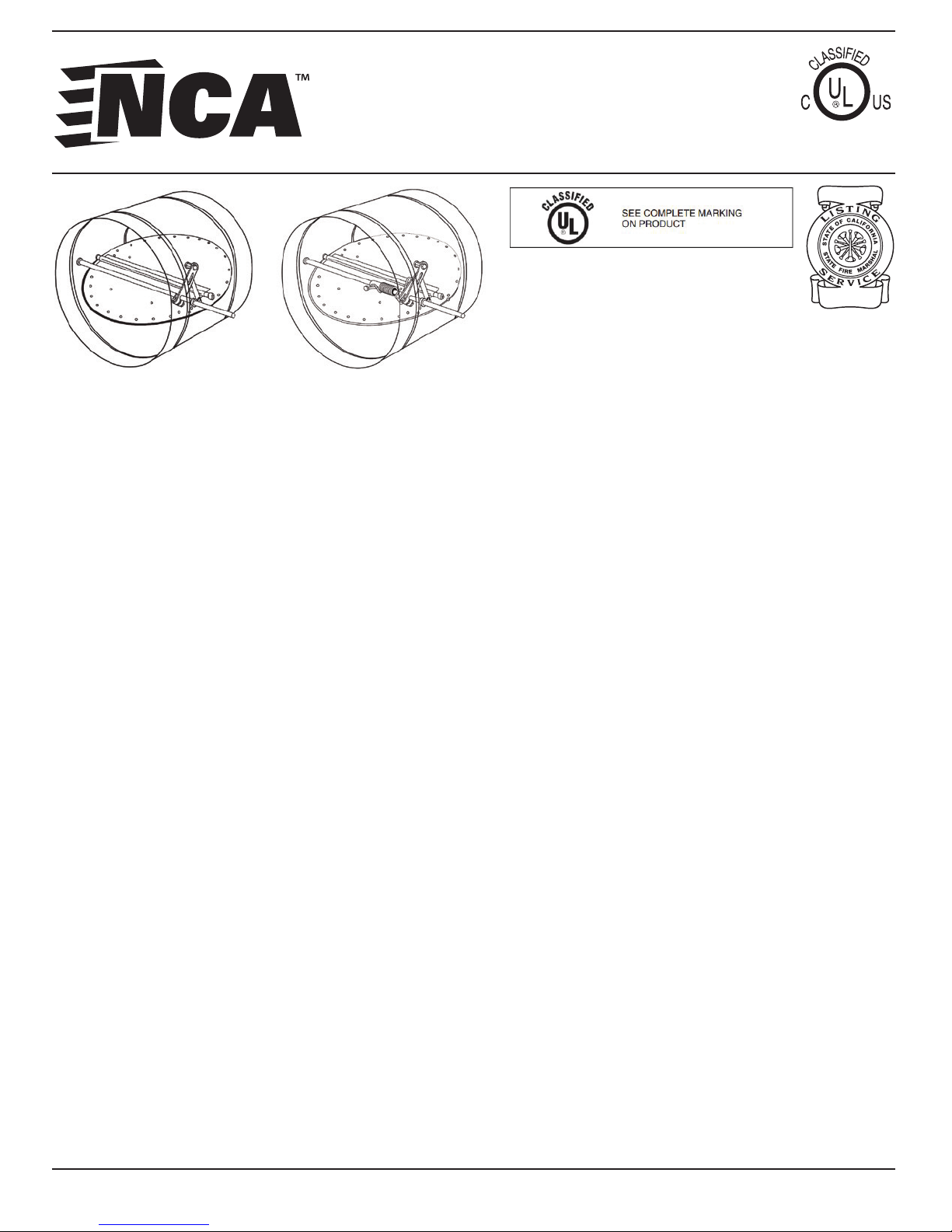
TRUE ROUND FIRE & FIRE/SMOKE
DAMPER INSTALLATION, OPERATION
& MAINTENANCE INSTRUCTIONS
FSD-RD
FD(D)-RD
Application & General Notes:
These installation instructions apply to static Fire, dynamic Fire
and Combination Fire/Smoke Dampers of the true round types
mounted in the plane of a UL* approved fire partition. The
dampers are designed for operation in the vertical or horizontal
orientation with the blade running horizontal.
Safety Warning:
Read all installation, operating and maintenance instructions
thoroughly before installing or servicing this equipment.
Improper installation, adjustment, alteration, service or
maintenance can cause property damage, injury or death.
R8218
UL/ULC File: R8218
New York BSA/MEA Listing: 79-03-M
California State Fire Marshall Listing: 3235:1721:0100
and 3225-1721:0102
The following installation instructions are UL
approved to be used with the following NCA
Models: FSD-RD-211, -212, FD and FDD-RD.
Installation Supplements:
- Installing Fire and Combination Fire/Smoke
Dampers in a Shaft Wall
- Framing Requirements for Wood or Steel Stud Walls
- UL Approved Breakaway Duct Connections
- Optional Sealing of Dampers in Fire and Smoke
Rated Walls or Floors
- Installing the SL-2000 Smoke Detector
- Field Modification of Factory Supplied Sleeves
- Installing Fire and Fire/Smoke Dampers in Concrete
Floor with Steel Deck
Other Installation References:
Receiving & Handling:
Check for damage when this product is received. If damage is
found, record all necessary information on the bill of lading and
file a claim with the final carrier. Check to be sure that all parts
of the shipment are accounted for.
*When UL is referred to in this document, it represents UL/ULC
(Underwriter’s Laboratories of United States and Canada).
This IOM manual is the property of the owners, and is required for future
maintenance. Please leave it with the owner when the job is complete.
1
- Out-of-Wall Fire and Fire/Smoke Damper IOM
- Combination Fire/Smoke Damper IOM
- Fire Damper IOM
Electrical Guidelines:
Electrical input may be needed for products discussed
within this IOM. All wiring shall be done in accordance
with the latest edition of the National Electrical Code
ANSI/NFPA-70, any local codes that may apply and
wiring diagrams developed in compliance with the job
or project design and specifications.
Electrical input work should be performed by a
qualified electrician. Verify power before wiring
actuator. NCA is not responsible for damage to or
failure of the unit caused by incorrect field wiring.
Follow all instructions carefully.
IOM - TRUE ROUND FIRE & FIRE/SMOKE DAMPERS - 1016
NCA MANUFACTURING INC. • 1985 CARROLL ST. • CLEARWATER, FL 33765 • 727.441.2651 • www.ncamfg.com
Page 2

TRUE ROUND FIRE & FIRE/SMOKE DAMPER INSTALLATION,
OPERATION & MAINTENANCE INSTRUCTIONS
TABLE OF CONTENTS
Pre-Installation Guidelines ............................................................................................................................
Size Table for NCA True Round Fire & Fire/Smoke Dampers .......................................................
Damper Sleeves & Mounting Clips ...........................................................................................................
2 Angle Method of Installation ....................................................................................................................
1 Angle Method of Installation ....................................................................................................................
Actuator Connections ....................................................................................................................................
True Round Fire & Fire/Smoke Damper Operation, Testing & Maintenance ..........................
Pre-Installation Notes and Guidelines:
These notes and guidelines are formulated in order to aid in completing the damper installation in a
timely and efficient manner.
A. Inspect damper for damage before installing.
B. Dampers must be installed free from twisting or racking.
C. DO NOT compress or stretch the damper into the opening.
D. DO NOT lift the damper by the blades or actuator (handle damper using frame or sleeve).
E. The damper must be protected from dirt, dust and foreign materials before and after installation.
F. When painting, wall-texturing, insulating or any other foreign material is being sprayed within 5 feet of the damper, the
damper must be sufficiently covered and protected.
G. Suitable access inside the duct and to the damper must be created for inspection and service of the damper per NFPA
90A and local authority having jurisdiction.
2
2
3
4
5
6
6
Maximum & Minimum Size Smoke Dampers:
Model Vertical Horizontal
FSD-RD-211
FSD-RD-212
FD-RD
FDD-RD
(All dimensions in parentheses () are in millimeters.)
2
8” - 24”
(203-610)
8” - 24”
(203-610)
8” - 24”
(203-610)
8” - 24”
(203-610)
8” - 24”
(203-610)
8” - 24”
(203-610)
8” - 24”
(203-610)
8” - 24”
(203-610)
IOM - TRUE ROUND FIRE & FIRE/SMOKE DAMPERS - 1016
NCA MANUFACTURING INC. • 1985 CARROLL ST. • CLEARWATER, FL 33765 • 727.441.2651 • www.ncamfg.com
Page 3
TRUE ROUND FIRE & FIRE/SMOKE DAMPER INSTALLATION,
OPERATION & MAINTENANCE INSTRUCTIONS
FIRE & FIRE/SMOKE DAMPER SLEEVES & MOUNTING CLIPS:
Damper Sleeves:
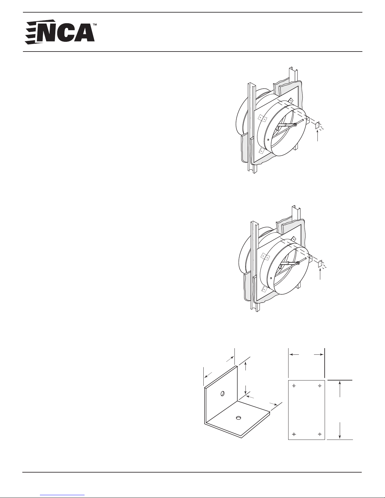
All true round fire and fire/smoke dampers must have an
integral sleeve (see Figure 1).
Guidelines:
1. Sleeves must be of the SAME GAUGE or heavier than
the duct to which it is attached if one of the UL approved
breakaway connections is used (see seperate “UL App roved Breakaway Duct Connections” supplement).
2. Gauges shall conform to SMACNA or ASHRAE duct
standards.
3. Sleeves shall not extend beyond the fire barrier more
than 16” (406mm) on the operator side or 6” (152mm) on the
opposite side.
4. The connecting duct shall terminate at the
integral sleeve and is connected by using either of the
following:
A. Minimum of 3 - #10 sheet metal screws spaced equal
distance around the sleeve for 22” (559mm) and ~
smaller duct.
B. Minimum of 5 - #10 sheet metal screws spaced equal
distance around the sleeve for greater than 22”
(559mm) duct.
C. 4” (101mm) drawband.
5. Clearance between the damper sleeve and the round or
square wall opening shall be a minimum of 1/2” (13 mm)
and a maximum of 1” (25mm).
Note: When installing the round damper into a square
opening, these clearances refer to the middle point of each
side of the square, not the corners.
6. Damper will be factory supplied with one retaining plate
secured to the damper sleeve on the operator side of the
damper.
Mounting Clips:
A minimum of 4 equally spaced 20 gauge galvanized steel clip
angles (see Figure 3) shall be attached to both the integral
sleeve and the retaining plate (see Figures 1 and 2). The clip
angles shall be attached with 1/8” (3.2mm) rivets, #10 x
1/2” (12.7mm) steel metal screws, bolts or welds.
Note: In metal stud/gypsum applications, the retaining plate
may be in front of or behind the gypsum, directly against the
metal studs.
Typical stud or masonry opening. (Refer to the Framing Requirements for
Typical masonry or metal stud opening. (Refer to the Framing Requirements
1-1/2”
(38 mm)
Clip Angle Detail 20 Ga.
(1) Galv. Steel
Figure 1: Angles on 2 Sides
Splice Clip
(see Fig. 3)
Wood or Steel Stud Walls For Fire and Fire/Smoke
for Wood or Steel Stud Walls For Fire and Fire/Smoke
Dampers In Drywall Partitions)
Figure 2: Angle on 1 Side
Dampers In Drywall Partitions)
Figure 3: Mounting Clips
1-1/2”
(38 mm)
1-1/2”
(38 mm)
Splice Clip
(see Fig. 3)
1-1/2”
(38 mm)
Same length as
cut in damper/
retaining plates
Splice Clip Detail
3
NCA MANUFACTURING INC. • 1985 CARROLL ST. • CLEARWATER, FL 33765 • 727.441.2651 • www.ncamfg.com
IOM - TRUE ROUND FIRE & FIRE/SMOKE DAMPERS - 1016
Page 4
TRUE ROUND FIRE & FIRE/SMOKE DAMPER INSTALLATION,
OPERATION & MAINTENANCE INSTRUCTIONS
2 ANGLE METHOD INSTALLATION:
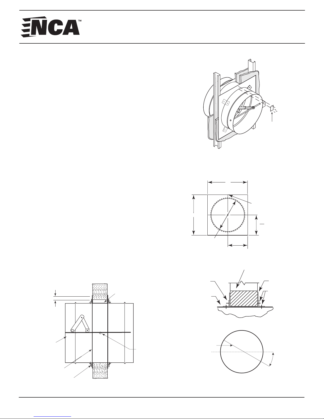
In this install method, the damper shall be installed in a stud/
gypsum or masonry fire partitition in the vertical or horizontal
position (blade shaft running horizontally within the parameters
of Detail A) with a retaining plate flush against both sides of the
fire partition (see Figure 4).
Guidelines:
The Two Angle Method (Figure 4) is approved for the
following:
A. Masonry/concrete or stud/gypsum partitions
B. 1 ½ Hour rated True Round Fire or Fire/Smoke Dampers
C. Vertical or horizontal orientation
D. All UL approved sizes shown in Table 1 on page 2 of this
IOM
Installation:
1. With the factory installed retaining plate flush to the fire
partition, place another retaining plate (if manufactured
in the field - see Figure 5) on the opposite side of the damper
sleeve and slide it forward until it becomes flush with the
opposite side of the partition.
2. Place the Splice Clip (see Figure 3 on page 3) over the cut
portion of the retaining plate and secure it with 4 - #10 sheet
metal screws or rivets as shown in Figure 4.
3. Secure the clip angles (see Figure 3 on page 3) to the
retaining plate and damper sleeve as illustrated in Figure 4,
6 and 7.
Figure 7: Cross Section of
Damper in a Wall (Floor Similar)
1” Min. Typ.
(25.4 mm)
Clearance
Figure 4: Angles on 2 Sides
with Splice Clips
Splice Clip
(see Fig. 3)
Typical masonry or metal stud opening. (Refer to the Framing
Requirements for Wood or Steel Stud Walls For Fire and Fire/
Smoke Dampers In Drywall Partitions).
Figure 5: Retaining Plate Detail
B
A
D
B
2
All dimensions in inches
A and B = Damper Dia.
plus 3” (76 mm)
Cut (Cover with
Splice Clip)
D
+ 1-1/2”
2
(38 mm)
Figure 6:
UL Approved Wall
or Floor Design
Clip
Angle
Damper
Sleeve
Retaining
Plate
Fastener
2 Angle
Installation Method
Auxiliary
Operating
Jackshaft
Factory Supplied
Plate
Angle
4
NCA MANUFACTURING INC. • 1985 CARROLL ST. • CLEARWATER, FL 33765 • 727.441.2651 • www.ncamfg.com
Blade
Shaft
Detail A
Axle
30˚
+/- 30˚ Max. Off Horizontal
(in either direction)
IOM - TRUE ROUND FIRE & FIRE/SMOKE DAMPERS - 1016
Page 5
TRUE ROUND FIRE & FIRE/SMOKE DAMPER INSTALLATION,
OPERATION & MAINTENANCE INSTRUCTIONS
1 ANGLE METHOD INSTALLATION:
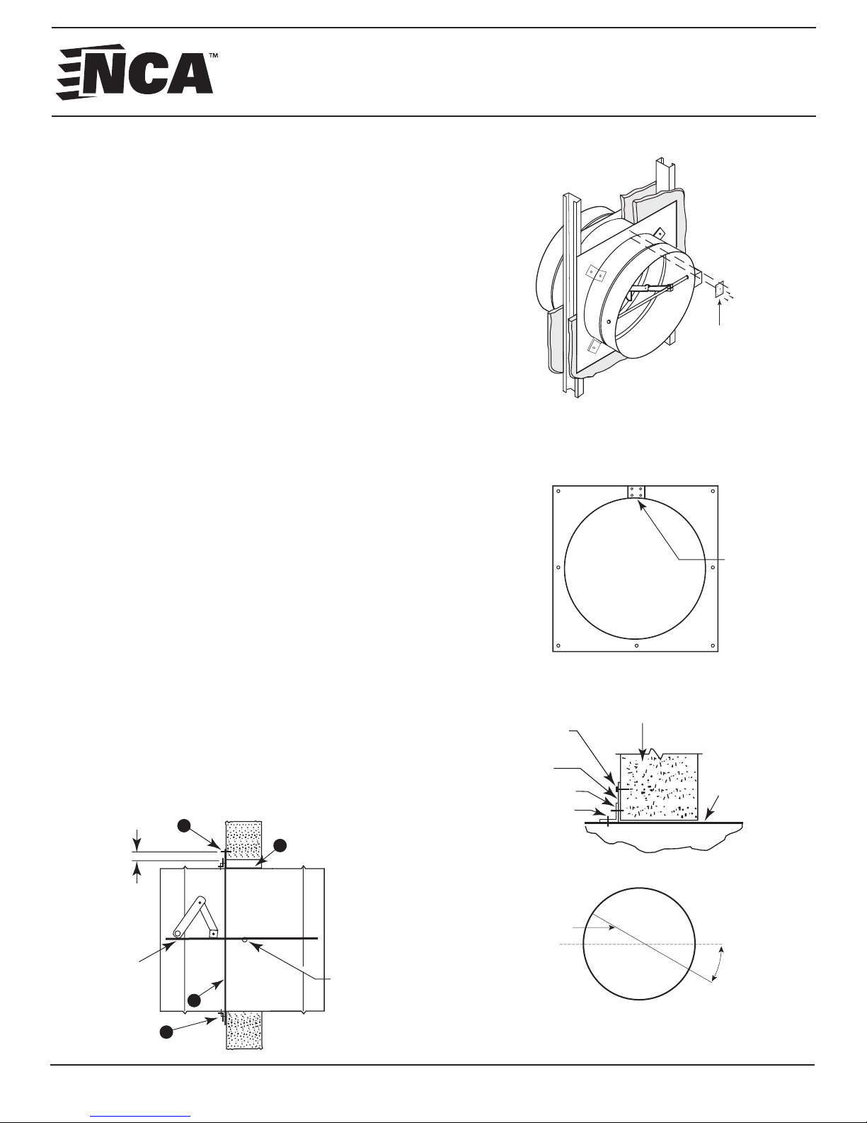
In this install method, the damper may also be installed in a
steel stud/gypsum, or masonry wall, in a vertical position
(blade running horizontally within the parameters of Detail
B), with a retaining plate on one side of the wall.
Guidelines:
The One Angle Method (Figure 8) is approved for the
following:
A. Masonry/concrete walls and steel stud/gypsum walls
B. 1 ½ Hour rated True Round Fire or Fire/Smoke Dampers
C. Vertical orientation
D. All UL approved sizes shown in Table 1 on page 2 of this IOM
Installation:
A. With the factory installed retaining plate flush to the fire
wall, place 8 screws equal distance around the perimeter
of the retaining plate per the following:
1. For steel studs use #10 sheet metal fasteners
long enough to penetrate the metal stud by 1/2” (13mm)
minimum
2. For masonry walls use #10 x 1-1/4” (32mm) masonry
screws
B. Refer to Figure 9 for placement of screws. Fasteners
shall be placed in each corner and halfway between the
corners as shown.
C. Place the Splice Clip (see Figure 3 on page 3) over the cut
portion of the retaining plate and secure it with 4 - #10 sheet
metal screws or rivets as shown in Figure 4.
D. Secure the clip angles (see Figure 3 on page 3) to the
retaining plate and damper sleeve as illustrated in Figure 8,
10 and 11.
Figure 11: Cross Section of
Damper in Wall
1” Min. Typ.
(25.4 mm)
6B
3
Figure 8: Angle on 1 Side
with Splice Clips
Splice Clip
(see Fig. 3)
Typical masonry or metal stud opening. (Refer to the Framing
Requirements for Wood or Steel Stud Walls For Fire and
Fire/Smoke Dampers In Drywall Partitions)
Figure 9: Retaining Plate Detail
Cutline on
retaining
plate
(Cover with
Splice Clip)
Figure 10
UL Approved Wall
Fastener
Retaining
Plate
Clip Angle
Fastener
or Floor Design
Damper
Sleeve
1 Angle
OPTION 2
Installation Method
Auxiliary
Operating
Jackshaft
4
5
5
NCA MANUFACTURING INC. • 1985 CARROLL ST. • CLEARWATER, FL 33765 • 727.441.2651 • www.ncamfg.com
Blade
Shaft
Detail B
Axle
30˚
+/- 30˚ Max. Off Horizontal
(in either direction)
IOM - TRUE ROUND FIRE & FIRE/SMOKE DAMPERS - 1016
Page 6

TRUE ROUND FIRE & FIRE/SMOKE DAMPER INSTALLATION,
OPERATION & MAINTENANCE INSTRUCTIONS
Actuator Connections (if applicable):
Electrical or pneumatic connections to damper actuators should be made in accordance with wiring and piping diagrams
developed in compliance with applicable codes, ordinances and regulations. Be sure to check actuator for proper voltage
and current draw. Tampering with the actuator’s installation or connecting the actuator to an improper voltage and current
may void the warranty.
DAMPER OPERATION, TESTING & MAINTENANCE
The procedures discussed here are intended to insure that nothing interferes with a damper’s proper operation and to
identify and eliminate a number of potential situations that could occur and interfere with said operation.
Fire & Fire/Smoke Damper Operation:
All NCA fire/smoke dampers are operated at the factory, however pre-installation testing of its operation should be conducted. Wire the actuator (if applicable) per correct wiring diagrams. Applying power to the actuator should drive the
damper open and disconnecting power should activate the actuator’s internal springs and drive closed.
WARNING: During any operating, inspection or testing of fire or fire/smoke dampers, NCA recommends the following:
1. Caution is advised when removing power from the damper’s actuator or removing the fusible link. Actuators have
very strong internal springs that may slam closed causing an abrupt interruption of airflow. As this could cause dam age to ductwork, consideration should be given to conducting these tests without system airflow.
2. When removing power from the actuator to check damper operation, be sure to keep fingers, hands and any other
body parts out of the blade travel path to prevent injury.
3. Check proper actuator operation. If defective, contact damper manufacturer for replacement procedures.
Fire & Fire/Smoke Damper Testing:
All fire and fire/smoke dampers and their actuators (if applicable) shall be visually inspected and cycled at specific time
intervals in accordance with the local building codes or the latest editions of NFPA 80, 90A, 92A, 92B, 101, 105, AMCA 50303, local codes and UL 864. Also refer to the actuator manufacturer’s recommendations.
IMPORTANT NOTE: Do not apply a heat gun, flame or any heat producing device directly to the thermostat. Simply
disconnecting the power to the actuator(s) shall be sufficient for testing procedures.
Fire & Fire/Smoke Damper Maintenance:
Fire and Fire/Smoke Life-Safety related dampers that are properly applied, equipped with the appropriate UL labels, appropriately installed, and demonstrated to function as intended through a building commisioning process should require no
specific preventive maintenance. However, NCA recommends that obstructions, dirt build up, and any rust or corrosion be
removed using mild solvents or detergents. No lubrication is required, however if it is desired, damper tracks and blade
hinges may be lubricated using a dry lubricant. Never use a petroleum based lubricant as it will attract dust and
eventually impede a damper’s operation.
Message from NCA:
This installation, operation and maintenance instruction document has been reviewed and approved by the
Underwriter’s Laboratories.
As a part of NCA’s continuous improvement program, NCA reserves the right to make further improvements or changes
without notice.
6
NCA MANUFACTURING INC. • 1985 CARROLL ST. • CLEARWATER, FL 33765 • 727.441.2651 • www.ncamfg.com
IOM - TRUE ROUND FIRE & FIRE/SMOKE DAMPERS - 1016
 Loading...