

Page 1
ImageMaster™ D-40
Card Personalization
System
Operation Guide
NBS-1020-080205
P/N 13456
Revision —
Page 2

Proprietary Notice
All drawings and information herein contained are the sole property of NBS Technologies Inc.,
(NBS) and must be returned at the request of NBS. You may not reproduce, store or convert this
material in any form, either mechanical or electronic, without the written permission of an
authorized representative of NBS Technologies Inc.
We have made every effort to ensure the accuracy of this material as of the time of printing.
However, as this equipment and this manual are subject to change without notice, NBS
assumes no responsibility or liability for any errors or inaccuracies that may appear in this
manual. NBS assumes no responsibility what so ever for the uses made of this material or
decisions based on its use. This manual is supplied for informational use only and should not
be construed as a commitment by NBS.
NBS Technologies Inc., the NBS Technologies logo, ImageMaster and SmartSys are
trademarks of NBS Technologies Inc.
All other brand or product names are the trademarks or registered trademarks of their
respective holders.
NBS equipment is manufactured under one or more of the following U.S. patents, their foreign
equivalent or patents pending:
4,686,898; 4,754,787; 4,755,069; 4,784,059; 4,789,420; 4,866,545; 4,900,168;
4,969,760; 5,406,422; 5,503,514; 5,837,991; 6,089,457; 6,131,817; 6,142,370;
6,439,567; 6,588,673; 6,352,206 B1; 6,484,780 B2; 54,726,719, (EP462,201);
Address for:
NBS Technologies Inc.
Corporate Headquarters
Canada
703 Evans Avenue
Toronto, Ontario
M9C 5E9 Canada
tel: +1 416.621.1911
fax: +1 416.621.8875
Website: http://www.nbstech.com
Customer Service: +1 416-840-8620 / 800-524-0419
Canada Only: +1 416-840-8627/ 800-565-9033
© Copyright 2008, NBS Technologies Inc., Paramus, New Jersey 07652.
United States
70 Eisenhower Drive
Paramus, New Jersey
United States 07652
tel: +1 201.845.7373
fax: +1 201.845.3337
United Kingdom
7 Byfleet Technical Centre
Canada Road, West Byfleet, Surrey
KT14 7NB United Kingdom
tel: +44 01932.351531
fax: +44 01932.351382
Page 3

D-40 Operation Guide i
Table of Contents
Chapter 1 Introduction .................................................... 1-1
1.1 Product Description ............................................. 1-1
1.2 Installation .................................................... 1-2
1.3 Familiarization with Unit .......................................... 1-2
1.4 Input Hopper .................................................. 1-4
1.5 Card transport System........................................... 1-4
1.6 Card Cleaning System ........................................... 1-4
1.7 Optional Magnetic Encoding ...................................... 1-5
1.8 Optional SmartCard Programming .................................. 1-5
1.9 Flipper Mechanism ............................................. 1-5
1.10 Thermal Printing ............................................... 1-5
1.11 Output Stacker - Reject Area...................................... 1-5
1.12 Liquid Crystal Display ........................................... 1-6
1.13 Operator Control Panel .......................................... 1-6
Chapter 2 Main Menu - Basic Functioning .................................... 2-1
2.1 General ...................................................... 2-1
2.2 Keyboard and LCD Display ....................................... 2-1
2.3 Power-up and Fundamentals ...................................... 2-1
2.4 Front Panel Switches ............................................ 2-2
2.5 Main Menu Selections ........................................... 2-2
2.6 Print Option ................................................... 2-3
2.7 Layout Option ................................................. 2-3
2.8 Online Option.................................................. 2-4
2.9 Utility Option .................................................. 2-4
2.10 Counters Option ............................................... 2-4
2.11 Start-up ...................................................... 2-4
Chapter 3 Printing Cards .................................................. 3-1
3.1 External Printer ................................................ 3-1
3.2 Standalone Printer ............................................. 3-1
3.3 Print Command ................................................ 3-1
Chapter 4 Creating Layouts ................................................ 4-1
4.1 File Sub-menu ................................................. 4-1
4.2 Card Layout Considerations ...................................... 4-2
4.3 Layout (Create & Edit) Sub-menus ................................. 4-4
4.4 File (Create & Edit) Commands - Type Selection ....................... 4-4
4.5 Change to Next Field ............................................ 4-5
4.6 Utility/File/Create or Edit/Layout (Font Parameters) ..................... 4-8
4.7 Utility/File/Create or Edit/Layout (Barcode Parameters) .................. 4-15
4.8 Utility/File/Create or Edit/Layout (Encode Parameters) .................. 4-21
4.9 Utility/File/Create or Edit/Layout (Image Parameters) ................... 4-24
4.10 Utility/File/Copy & Delete Commands ............................... 4-25
4.11 Utility/File/Download & Upload Commands ........................... 4-25
Page i Table of Contents
Page 4

ii NBS Technologies Inc.
4.12 Utility/File/SelBoot .............................................. 4-27
4.13 Utility/File/Status ............................................... 4-28
Chapter 5 Operator Maintenance ............................................ 5-1
5.1 General Cleaning ............................................... 5-1
5.2 Cleaning the Print Head .......................................... 5-1
5.3 Card Stock.................................................... 5-1
5.4 Ordering Consumable Supplies .................................... 5-2
5.5 Loading Cards ................................................. 5-2
5.6 Unloading Cards ............................................... 5-3
5.7 Replacing Printing Foil........................................... 5-4
5.8 Replacing Cleaning Tape ......................................... 5-5
Chapter 6 Error Messages ................................................. 6-1
Revision History ........................................................ RH-1
Critique Form .......................................................Last Page
Table of Contents Page ii
Page 5

D-40 Operation Manual 1-1
Chapter 1 - General Description
The following is provided to introduce your new ImageMaster™ D-40 printer.
1.1: Product Description
The ImageMaster™ D-40 printer is a table top, high speed, thermal card printer. The D-40
offers dual sided printing with parallel card processing capability. The D-40 is capable of
producing cards at speeds up to 4000 cards per hour (cph) single sided and 1200 cph in dual
sided mode. The D-40, as an option, supports magnetic strip encoding and programming of
the embedded chip on a Smart Card. It has 500 card capacity input and output hoppers. It
features large capacity roll of printing ribbon, capable of printing up to 12,000 cards per roll
(with 3" (7.62cm) of printing per card).
Physical Dimensions
Height: 23 inches (585 mm)
Width: 24 inches (610 mm)
Depth: 16 inches (407 mm)
Power requirements
Weight: 70 lbs (23.6 kg)
110-230VAC, 50/60 Hz, ? Amp Slow-Blow
FCC Class B, CE, and ETL approved
Operating Environment
Temperature range: 580 F to 800 F (150 C to 300 C)
Relative humidity: 20 to 65% non-condensing
Storage temperature: 230 F to 1580 F (-50 C to 700 C)
Storage humidity: 20% to 70% non-condensing
Plastic Cards Accepted
Type: PVC & composite PVC - including breakaway, key cards, & clear cards
Card Size: ISO 7810 (CR-80) - 3.375" x 2.125" (86 mm x 54 mm)
Card Thickness: 0.024" to 0.030" (0.61 mm to 0.76 mm)
Print Resolution
300 dots per inch (dpi) (11.8 dots per mm)
monochrome printing - up to 4000 single sided cph or 1200 dual sided cph
Maximum Print
0.100" +/- 0.010" from side edges of card
0.100" +/- 0.015" from top and bottom edges of card
Chapter 1 Page 1 General Description
Page 6

1-2 NBS Technologies Inc.
Connectivity
Serial
IP
Ethernet
Encoding/Programming
Magnetic
3 Tracks : ISO /IEC 7811
Write Speed: ?.? inches/second
Read Speed: ?.? inches/second
SmartCard
!SO7816 personalization
Clear Card
1.2: Installation
The D-40 printer is meant to be used in an office type environment, on top of a table or desk. If
the environment is comfortable for the operator the D-40 Series printer will work just fine. See
“Operating Environment” above. Adequate working space must be provided around unit,
especially for proper ventilation of internal components. The exhaust fan at rear of unit must
never be blocked. Should repairs be needed and to perform normal operating functions –
changing foil, loading cards, etc., a minimum of 10 inches, all around the unit, is recommended.
The D-40 Series printer will be installed by an NBS or Authorized Dealer trained technician.
The technician will also train the operator in the basic function of the system. The end user
will be asked to sign off on the final installation when completed to end user satisfaction.
1.3: Familiarization with Unit
The following identifies the major components of interest to operators.
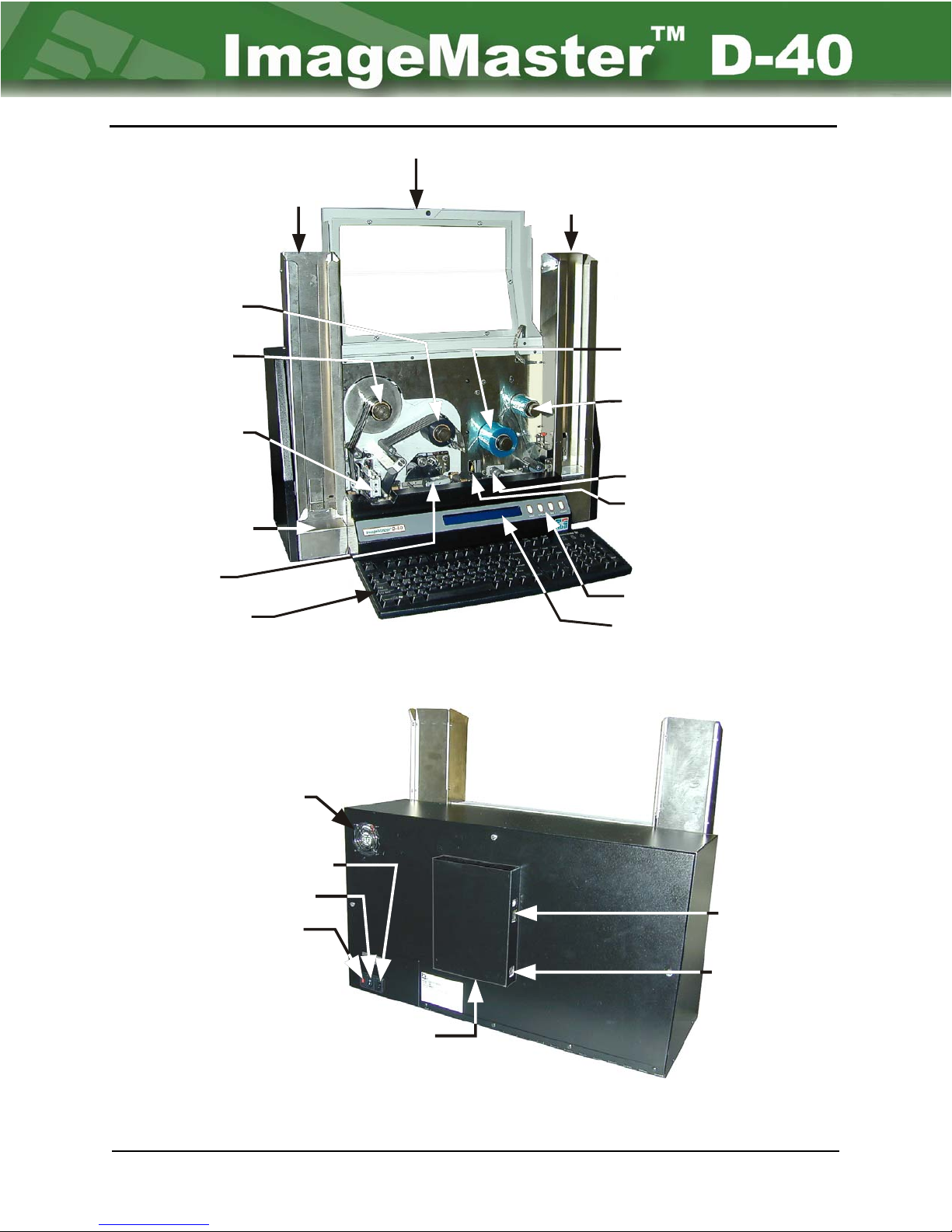
Figure 1-1 shows the front of the unit, while Figure 1-2 shows the rear of the unit. Except for
turning unit on, the operator mainly interfaces with the front of the unit via the keyboard, the
LCD panel, the switch panel. Other functions, such as loading and unloading cards, changing
printer foil and cleaning tape are also accomplished from the front of the unit, some requiring
the top front cover to be opened.
General Description Chapter 1 Page 2
Page 7
D-40 Operation Manual 1-3
Open Top Cover
Print Ribbon
Supply
Print Ribbon
Ta ke - up
Print Head
Reject Tray
Flipper
Keyboard
Output
Hopper
Input
Hopper
Cleaning Tape
Supply
Cleaning Tape
Ta k e- u p
Magnetic Encoding
SmartCard
Programming
Switch Panel
LCD Display
Figure 1-1 Front of ImageMaster™ D-40
Fan
AC Input
On / Off
Switch
Fuse
Communication PORT
Connectors (4 Serial)
Figure 1-2 Rear of ImageMaster™ D-40 unit
LAN Connector
Keyboard
Connector
Chapter 1 Page 3 General Description
Page 8
1-4 NBS Technologies Inc.
The ON/OFF switch is located at the rear of the unit, along with the various communication
connections. The depressed side of the rocker switch is the enabled function. With the “I”
depressed the system is ON. With the “O” depressed the unit is OFF.
The basic D-40 printer consists of the following major components:
• Card input hopper
• Card transport mechanism
• Card cleaning mechanism
• An optional magnetic encoder
• An optional SmartCard programming station
• Flipper mechanism
• Thermal printer
• Card output hopper
• Reject tray
• Forty (40) character each two (2) line LCD display
• Four button control switch panel
• Four serial 9 pin female PORT Communication connectors
• Network port connector
• AT style keyboard and connector
An Imagemaster™ D-40 configuration may also include a PC acting as a host or source of
the data used to produce cards.
The following brief descriptions are presented in the order of card movement through the unit.
1-4 Input Hopper
The INPUT HOPPER accepts CR-80 cards, with the capacity to hold at least 500 blank cards
(amount depending on thickness). The base of the hopper contains a Card Picker Assembly.
Fingers should never be placed into the hopper when the system is
! Caution:
ATTENTION!
in operation. Fingers can be injured by this mechanism when it is
pushing a card out of the hopper and into the Transport System.
Les doigts ne devraient jamais être placés dans le distributeur lorsque
le système est en marche. Les doigts peuvent être blessés par ce
mécanisme quand il pousse une carte hors du distributeur vers le
système de transport.
1.5: Card Transport System:
The CARD TRANSPORT SYSTEM consists of transport motors, a series of sprockets and
belts, and rubber rollers that will move the card in either direction as required.
General Description Chapter 1 Page 4
Page 9
D-40 Operation Manual 1-5
1.6: Card Cleaning System:
As the card enters the Transport System, both sides of the card are cleaned by a set of rollers
and a brush. The top roller of the set is softer and more adhesive than the bottom roller. Any
dust or debris that accumulates on the lower roller is transferred to the top roller.
Periodically, the cleaning tape comes in contact with the top roller, transferring any foreign
matter from the top roller to the cleaning tape. By default the cleaning cycle occurs after
every 5 cards, but the timing of this process is user adjustable.
The Cleaning Brush is constructed of nylon (90%) and brass (10%) bristles
NOTE:
mounted in a galvanized steel channel. The purpose of the brush is to remove
large pieces of debris and to discharge any static electricity from the passing cards.
1.7: Optional Magnetic Encoding
ISO magnetic encoding is available for tracks 1, 2, and 3. During the encoding process
information is first written on the desired track(s), then it is read and verified. If the information
encoded does not verify with what was written, a retry of the entire write and read process is
made. The number of retries is user defined. If the card cannot be verified within the set number
of retries, the card will be sent to the reject tray, and a error message is displayed on the LCD
Screen. Operator intervention is required.
1.8: Optional SmartCard Programming
As the card is positioned in unit a solenoid is activated bringing the programming head in
contact with the card chip. SmartCard programming is a pass through operation - the D-40
positions the card, an external source is used to program the chip.
1.9 Flipper Mechanism
This mechanism can flip the card so that the reverse side of card can be processed.
1.10: Thermal Printing
As the card is sensed entering the print area, the PRINT HEAD is lowered. The foil starts
moving, and the PRINT HEAD prints the first vertical line across the width of the card. The
density is 300 DPI. Raster data is sent to the head one line at a time, turning on respective
dots on the Print Head to apply heat to the foil in the correct locations to form the picture,
letter, or barcode. When the last line is printed, the head is raised and the foil stops moving.
The card is moved to the next operation.
The large capacity printing foil roll is loaded on spools present on the unit itself.
Chapter 1 Page 5 General Description
Page 10
1-6 NBS Technologies Inc.
1.11: Output Stacker - Reject Area
The OUTPUT STACKER is a vertical storage device. The upper portion holds all of the
acceptably produced cards. If the card is a reject it falls into the lower reject area. The
stacker can hold 500 acceptable .030" cards. The Reject tray holds fifteen rejected cards.
Fingers should never be placed into the hopper when the system is in
! Caution:
ATTENTION!
operation. Fingers can be injured by this mechanism when it is pushing a
card up into the hopper.
Les doigts ne devraient jamais être placés dans le distributeur lorsque
le système est en marche. Les doigts peuvent être blessés par ce
mécanisme quand il pousse une carte hors du distributeur vers le
système de transport.
1.12: Liquid Crystal Display:
The LIQUID CRYSTAL DISPLAY (LCD) is a two line, eighty (80) character display (2 lines of 40
characters each), installed on the front of the machine. It is used to provide operator prompts,
selection options during the utilities command functions, error messages, and the like. When
used for data entry it displays keyboard entries.
1.13: Operator Control Panel
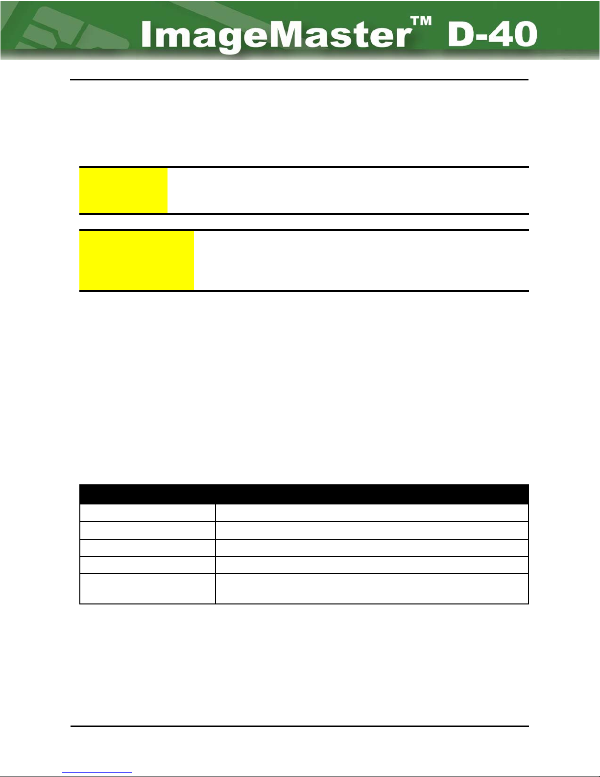
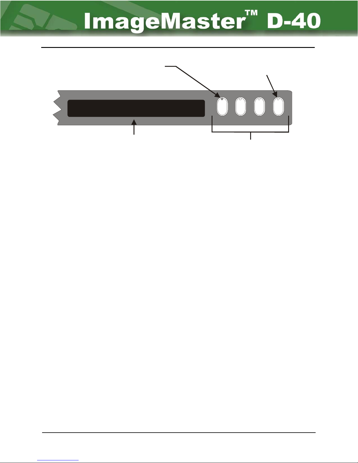
The operator control panel consists of four (4) push button switches as shown in Figure 1-3
and their functions are defined in Table 1-1.
D-40 Front Panel Button Selection
Command Button Button Function
WAIT
ONLINE Places unit online to a host over a network.
SW1 Application specific.
RESETS Resets the print mechanism and menu. (The machine can also
Suspends machine operation AFTER the current card.
be reset by pressing [CTRL] + [A] keys.)
Table 1-1
General Description Chapter 1 Page 6
Page 11
D-40 Operation Manual 1-7
LED for “Wait” button on
steady when in wait mode.
Print Layout Online Utility Counters
Front Panel Display
Figure 1-3 Front Panel
LED flashing on “Reset” button when the unit
is waiting for operator response. This indicates
that the machine is operating normally.
WAIT ONLINE SW1 RESET
Panel Buttons
Chapter 1 Page 7 General Description
Page 12
D-40 Operation Manual 2-1
Chapter 2 - Main Menu - Basic
Functioning
2.1: General
This chapter explains the various Main Menu settings and functions of the D-40 printer and
demonstrate basic operator functions.
2.2: Keyboard and LCD Display
The D-40 printer requires a 101 enhanced AT keyboard for data entry. All input from the
keyboard as well as menu options are displayed on two 40 character lines (a total of 80
characters) Liquid Crystal Display (LCD). The LCD is installed on the front of the unit. Beside
the description above, it provides the user with prompts, layout and format information, utility
parameters, as well as warnings and error messages.
2.3: Power-up and Fundamentals:
Apply power by depressing the “I” side of the power rocker switch located on rear of unit.
Immediately after powering the unit up, the software version is displayed for several seconds.
This is then followed by the initial or Main Menu. (Refer to Figure 2-1.)
Print Layout Online Utility Counters
Print a card using active layout
Figure 2-1: LCD Display of Main Menu
The blinking cursor indicates the currently highlighted menu option on the first line (as well
as an underscore below the first letter of the highlighted menu). The second line describes
the highlighted option’s function. In Figure 2-1, the highlighted menu option is “Print”, while
the description is “Print a card using active layout”.
Operation of the system relies on accessing the desired option or setting through a hierarchy of
menus and sub-menus. Some sub-menus or items may change, be added to, or subtracted
from based on previous choices within an option. The hierarchy may consist of many or few
levels depending on user decisions and requirements of the selected operation.
There are six keys on the keyboard that can be considered control keys when navigating
through the menus. They are:
• Right Arrow – Moves cursor right to next operation or selection.
• Left Arrow – Moves cursor left to previous operation or selection.
Chapter 2 Page 1 Main Menu
Page 13
2-2 NBS Technologies Inc.
• Down Arrow – Moves cursor down to next operation or selection.
• Up Arrow – Moves cursor up to previous operation or selection.
• Enter – Selects current or highlighted operation or selection.
• Escape – Returns to previous menu (from a sub-menu).
However, the Arrow keys work either horizontally or vertically (depending on the current menu
or option). For example, a user can only scroll through the Main Menu options by either the Left
or Right Arrow keys (horizontal direction), not the Up or Down Arrow keys (vertical direction).
Another way to access the menus is through use of the Number Lock Key Pad. When the
Number Lock is disabled, the pad can be used for navigation or enter commands. When the
Number Lock is enabled, the pad is used to enter numbers (when required) for data entry.
2.4: Front Panel Switches
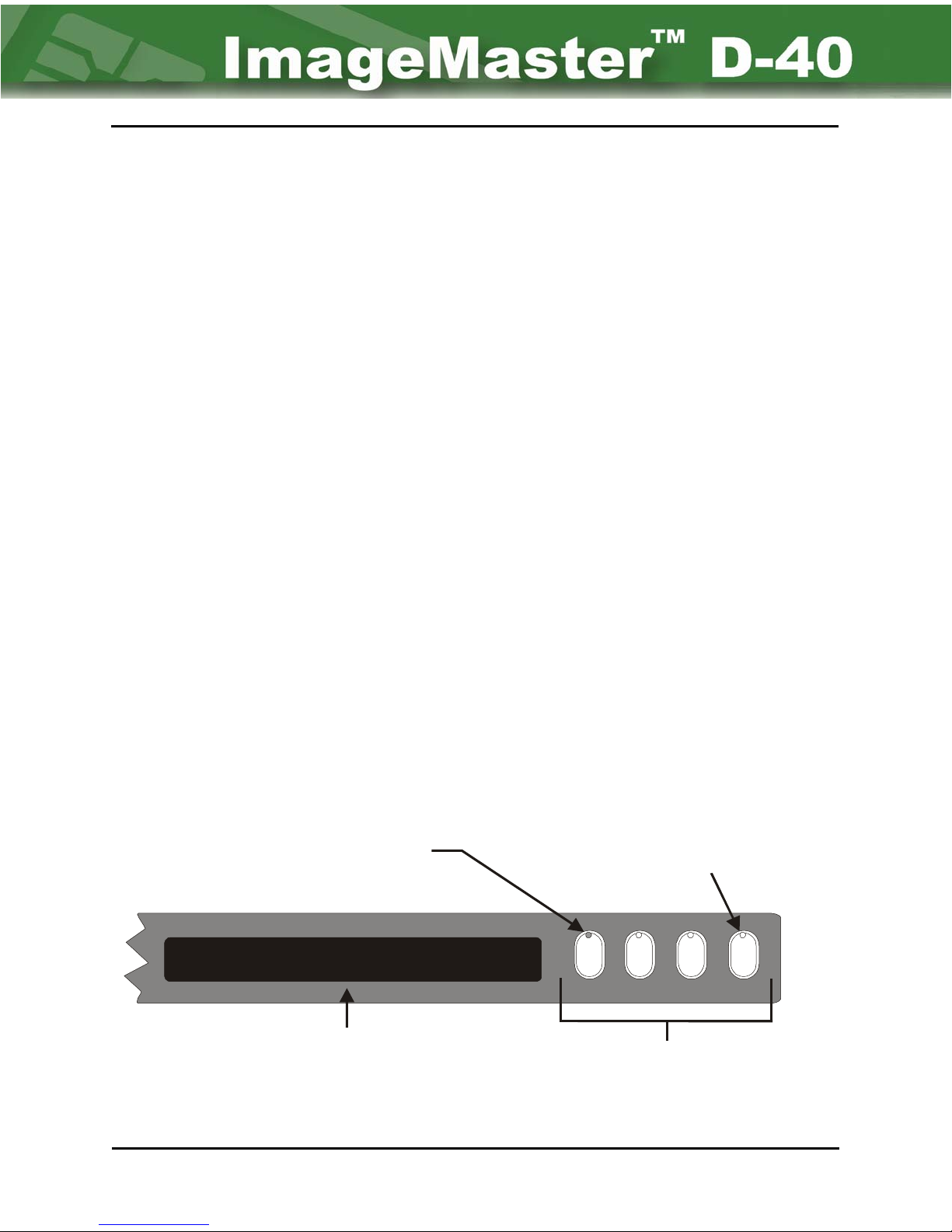
The front panel of the D-40 printer has four pushbutton switches. (Refer to Figure 2-2.)
These buttons will illuminate when activated by either the operator or the unit. These buttons
are defined as follows:
• WAIT - Suspends machine operation AFTER the current card.
• ONLINE - Places unit online to a host over a communication network.
• SW1 - Application specific.
• RESET - Resets the print mechanism and menu. (The machine can also be
reset by pressing [CTRL] + [A] keys.)
2.5: Main Menu Selections
As explained previously, the Main Menu appears after the machine has booted up. From this
point, the user selects the operation to be performed through the hierarchy of menus.
LED for “Wait” button on
steady when in wait mode.
Print Layout Online Utility Counters
Front Panel Display
Figure 2-2: Illustration of Front Panel
LED flashing on “Reset” button when the unit
is waiting for operator response. This indicates
that the machine is operating normally.
WAIT ONLINE SW1 RESET
Panel Buttons
Main Menu Chapter 2 Page 2
Page 14

D-40 Operation Manual 2-3
The top line of the screen displays the menu selection. Placement of the cursor (using the
Arrow keys) determines the menu highlighted and the comment seen on the second line of
the display:
• PRINT - Print a card using active layout.
• LAYOUT - Select local card layout.
• ONLINE - Enter online mode.
• UTILITY - System utilities.
• COUNTERS - Production counters.
Menu selection can also occur through use of the keyboard. By pressing the first letter of any
of the options, the machine highlights that particular option. Pressing the [ENTER] key while
that option is highlighted, selects that option. For example, on pressing the letter [U] and
[ENTER] key, the “Utility” option is selected; on pressing the letter [L] and [ENTER] key, the
“Layout” option is selected.
Once a Main Menu option has been selected, the Arrow keys can then be used (in
conjunction with other keys) to enter data, turn variables on/off, switch between multiple
choices of variables, and navigate through the hierarchy of menus.
2.6: Print Option
The Print option is probably the operator’s most commonly used feature. Whether the unit
has been reset or just turned on, the last layout in use will be available for printing. If this
layout is the one desired, depressing the [ENTER] key while the “P” in “Print” is highlighted
will start the printing process. Refer to next chapter for printing instructions. If it is not the
desired layout use the Layout command to select one of the other preprogrammed layouts.
Refer to paragraph 2.7 - Layout Option below to change layouts.
To create new layouts refer to Chapter 4 - Creating Layouts.
2.7: Layout Option
This main menu option is selected only to switch between the existing layouts stored in the
memory of the machine. To change the “Layout” option, move the cursor until it highlights the
“L” in “Layout” (in the Main Menu) and depress the [ENTER] key. The display screen in
Figure 2-4 will then appear. (All layouts are user defined. All layout names shown in Figure
2-3 are for illustration purposes only.)
Please select the current layout
Layout 1 Layout 2 Layout 3 Layout 4
Figure 2-3: Typical Front Panel Display for Layout selection
Chapter 2 Page 3 Main Menu
Page 15

2-4 NBS Technologies Inc.
As many layout names that there are room for will be displayed. However, if there are more
than can be shown, the list is scrolled through using either the left or right Arrow keys. The
list will then shift as you move through it, the first letter of each layout being highlighted.
Once the layout has been decided upon, it can be chosen by pressing the [ENTER] key.
Immediately after pressing the key, the user is returned to the Main Menu. The selected
layout becomes the “Active” layout – the one used to produce cards.
2.8: Online Option
This option is selected to allow a host computer to print using the D-40 printer, turning over all
control to the host. The communication link is established either via serial port or network
connection. During this process, the D-40 printer will emulate a HP Laserjet III printer.
To select the “Online” option, perform one of the following:
• By pressing the [O] button on the keyboard (while in the Main Menu) and then
pressing the [ENTER] key.
• Using the Arrow keys to highlight the letter “O”(while in the Main Menu) and then
pressing the [ENTER] key.
• By pressing the [ONLINE] button on the Front Panel.
2.9: Utility Option
The “Utility” option defines all operating parameters for the D-40 printer system. The “Utility”
option is not typically an operator function. Access to the Utility functions can be password
restricted This function is used to create, modify, or delete card layouts described later in this
manual. It is also used to activate and program system functioning. These Utility functions,
typically service technician functions, are defined in the D-40 Service manual.
2.10: Counters Option
The “Counters” option allows the viewing of the two production counters only. There is no
other associated function with this option.
2.11: Start-up
At Start-up, the D-40 Series automatically does a file check, looking for bad or missing files.
Also at this point, by holding down any key while the unit is “booting-up”, a boot menu will
appear. This menu allows the operator to switch between the several firmware versions that
may be resident in memory. (All new firmware upgrades in the field are downloaded to the
D-40 system by use of the “NBS Dashboard Program”.)
Main Menu Chapter 2 Page 4
Page 16

D-40 Operation Manual 3-3
Chapter 3 - Printing Cards
Printing cards is the basic function of the ImageMaster™ D-40. Cards are printed in one of
two basic modes of operation—as a standalone printer or as an external printer connected to
a PC or Host computer.
3-1 External Printer
When the D-40 is connected to a PC or other Host computer for all intense purposes it acts
like any other printer, excepting information from the PC and printing as instructed. The
operator interface is mostly with a software program loaded into the host computer – such as
the NBS SmartSys™ program and printer driver. The D-40 is selected as the active output
printer and gets it’s data and layout information from the Host computer. The basic operator
interface with the D-40 is to load and remove cards, change printer ribbon and cleaning foil
when needed. The printing instruction come from the Host computer when the computer is
directed to print cards. This connection is explained in the Card programing software
manuals – such as NBS SmartSys Operating Manual – and is not covered in this chapter.
This chapter is mostly concerned with Standalone Printer operation
3-2 Standalone Printer
When used as a standalone printer operator interface is mostly with the D-40 printer and the
keyboard. The card layouts are created within the D-40 firmware. The fields in the layout are
created expecting to see certain types of input data – fixed, variable, or host.
• Fixed data is permanent data entered in a field at the time of the card layout creation
and is the same for all cards.
• Variable data is keyboard entered data. It is unique data for each card but means
cards are printed one at a time.
• Host data is data coming from some external source, usually a PC over a network or
direct connect to the D-40. This is different from the “external printer” explanation
above in that the layout is within the D-40, only the data is coming from the external
source.
Creating card layouts is not the purpose of this chapter and is described elsewhere.
3-3 Print Command
The Print command on the main menu assumes that the active layout is the desired layout for
card creation. The last layout used will be the active layout when the unit is powered up.
Refer to Chapter 2- Main Menu description for instructions to change the active layout from
among the pre-designed layouts resident in the D-40.
Chapter 3 Page 3 Printing Cards
Page 17
3-4 NBS Technologies Inc.
A
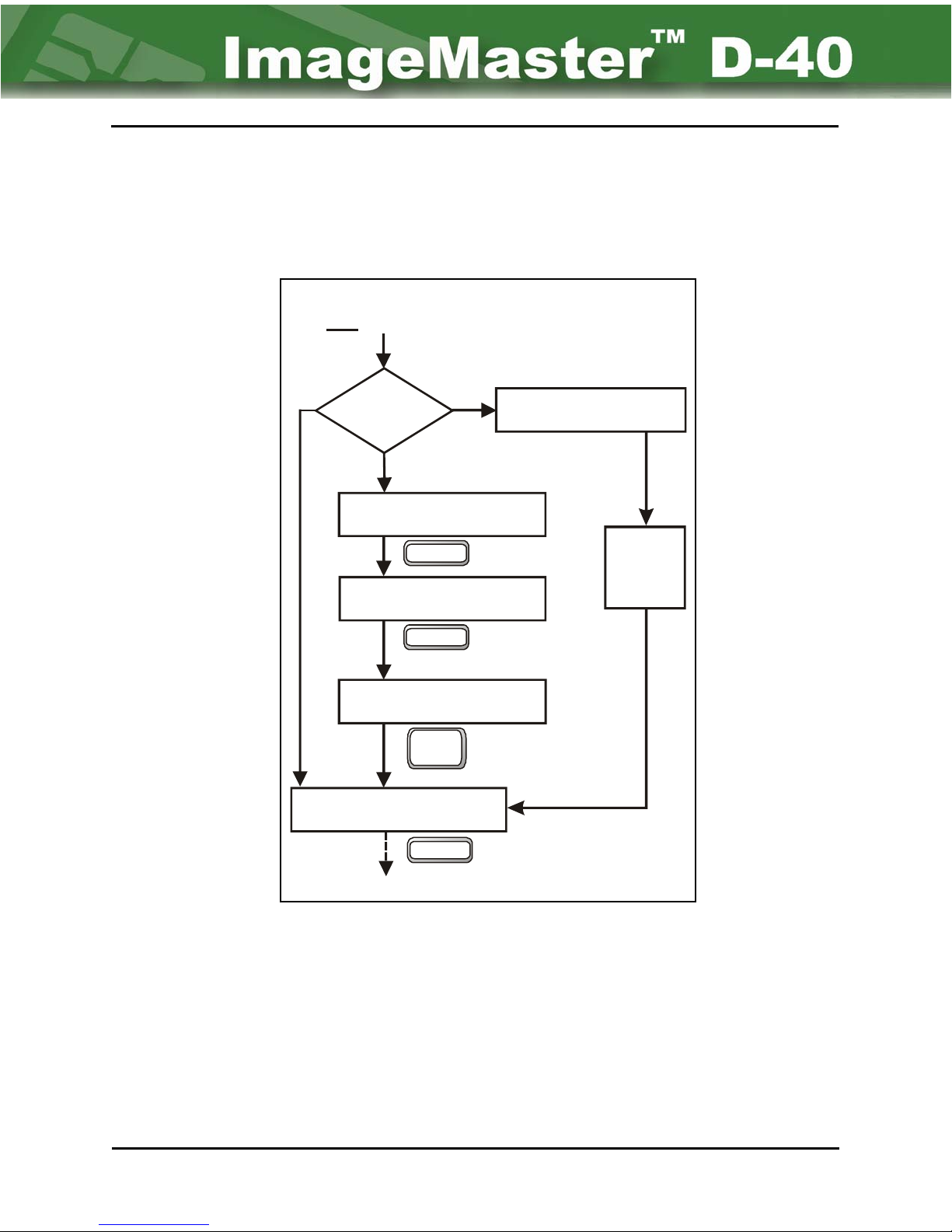
With the desired layout as the active layout simply pressing the keyboard [ENTER] key while
the “P” in “Print” is highlighted on the Main Menu starts the printing or card production cycle.
The type of data field (Fixed, Variable, Host) used in the layout determines the next prompt.
Once all data fields entries are completed the final prompt is: “# fo Cards”. (Refer to Figure 3-1)
Print
Fixed
# of Cards
Echos keyboard entry
Type of
Data
Vari able
Keyboard Field 1 Prompt
Echos keyboard entry
Keyboard Field 2 Prompt
Echos keyboard entry
Last Keyboard Field Prompt
Echos keyboard entry
Host
Enter
Enter
Print
Scrn
waiting Host Data
Data
Received
From
Host
etc.
etc.
The user enters a variable number from 1 to 9999. (For example, enter “20” as the amount of
card copies from the present layout you wish to print.) After the number has been typed in,
pressing the [ENTER] key will validate the number and begin the printing process.
As the printing occurs, the display tracks the printing process. This continues until either the
machine is stopped, or the number of total cards (number entered) is reached.
Printing Cards Chapter 3 Page 4
Enter
Prints
Figure 3-1 Print Display Screens
Page 18

D-40 Operation Manual 3-5
The machine is “Busy” during printing and can be stopped by pressing the [RESET] button on
the Front Panel. If the keyboard [ESC] button is pressed, the machine will continue printing
the current card before stopping and returning to the Main Menu. To interrupt and
immediately stop the machine during printing, press the [WAIT] button on the Front
Panel. This will temporarily stop the printing until the [WAIT] button is pressed again to
resume the operation.
Chapter 3 Page 5 Printing Cards
Page 19

3-6 NBS Technologies Inc.
Printing Cards Chapter 3 Page 6
Page 20
D-40 Operation Manual 4-1
Chapter 4 - Creating Layouts
Layouts are created starting with the Utility option on the Main Menu. This function can be
password restricted.
4.1: File Sub-menu
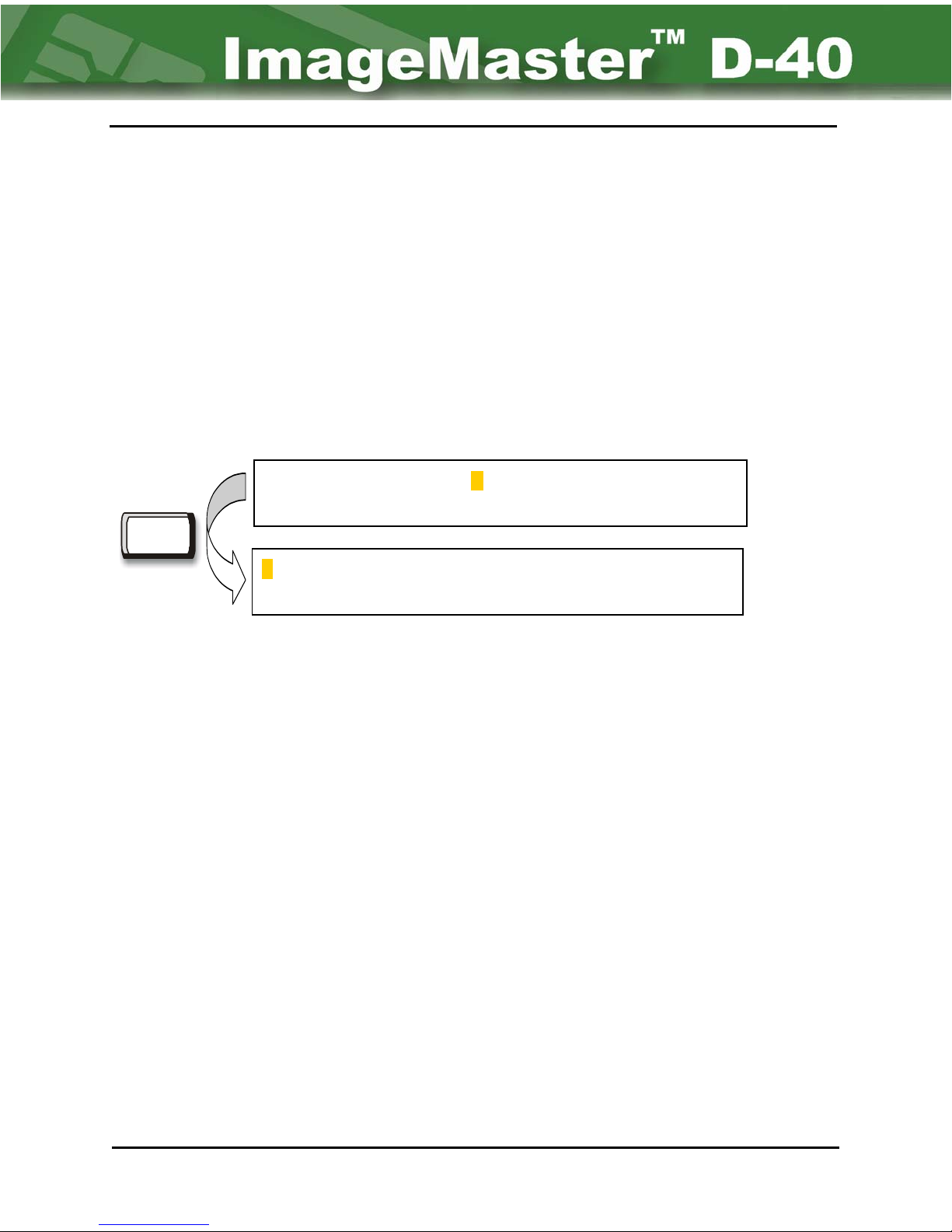
The “Utility / File” sub-menu is displayed by first moving the cursor until it highlights the “U” in
the “Main” menu. Next, the [ENTER] key is depressed. The Utility menu screen will then
appear. (See Figure 4-1.) Ensuring that the “F” (for File) in the “Utility” menu is highlighted
by the cursor in the second screen, the [ENTER] key is pressed once more. The “Create”
sub-menu screen will then appear.
Enter
From the Utility / File sub-menu, the user can:
• Create an new card layout.
• Edit an existing card layout.
• Copy an existing card layout, font, image, or firmware file.
• Delete an existing card layout.
• Download an existing host layout, font, image, Kanji, or firmware.
• Upload an existing D-40 printer layout, font, image, Kanji, or firmware.
Print Layout Online Utility Counters
System Utilities
File Comm System User Exit
Create or modify a card layout.
Figure 4-1 Going to “File” sub-menu
Main Menu
Utility Menu
• SelBoot - select a boot file.
• Status - display the file system status.
• Exit the current menu.
As with all other menus, highlight the desired option with the cursor and depress the [ENTER]
key. The D-40 printer will immediately display the option’s sub-menu.
Chapter 4 Page 1 Creating Layouts
Page 21

4-2 NBS Technologies Inc.
4.2: Card Layout Considerations
Before attempting to create or edit a layout, decisions must be made as to what the finished
card will look like (formatting the card). Some considerations that should be considered are
listed below. However, this is not intended as an all inclusive list.
• What specific fields will be used: Font, Barcode, Image, Encode, etc.?
• What should the fields contain?
• Where should the fields appear on the card?
• What field length is allowed?
• What is the minimum number of characters in a particular field?
• Is the text to be fixed?
• What field names are to be used?
• What are the allowable characters: digits, alpha, all?
• Is Mod 10 to be used?
• Are there transfer fields: source or destination?
• What is the barcode orientation?
• What type of barcode is to be used?
• Should the barcode be human readable?
• Is data coming from a host?
• What is to be used for card layout creation: Conquest Lite™ or the
resident firmware?
Creating Layouts Chapter 4 Page 2
Page 22
D-40 Operation Manual 4-3
UTILITIES / FILE MENU
Create Edit Copy Delete Download Upload SelBoot Status Exit
Display file system status
Select boot file
Upload file to host via serial port
Download file from host via serial port
Delete file
Copy file to new name
Edit existing file
Create a file
Layout Exit
Layout Exit
Please select a layout to edit: ( )
Enter new layout name: ( )
Type :
Font / Barcode / Encode / Image
enter 16 characters
enter 16 characters
Typ e:
Font / Barcode / Encode / Image
Chapter 4 Page 3 Creating Layouts
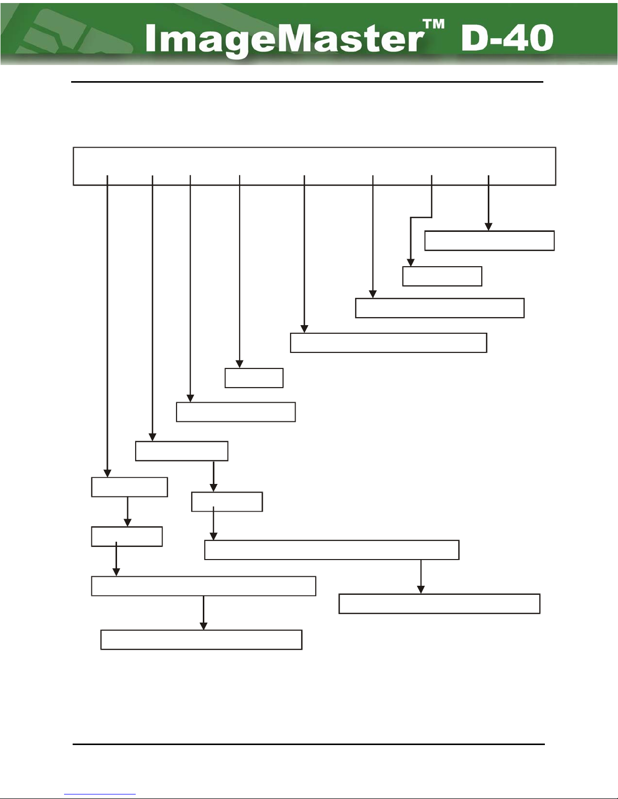
Figure 4-2: Utility Menu Overview
Page 23
4-4 NBS Technologies Inc.
4.3: Layout (Create & Edit) Sub-menus
The “Create” function menu is used to design a new card layout, while the “Edit” function
menu is used to modify an existing design. With exception of the first screen, selecting
either will bring up the exact same menu screens. (However, to select a layout for
immediate printing, it must be chosen from “File” under the Main Menu. See Figure 4-2.)
To access either of these preferences from the “File” sub-menu, highlight the desired function
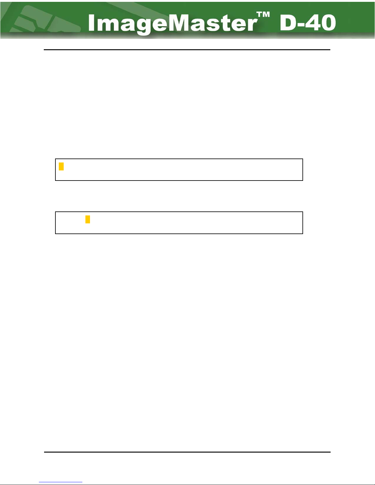
with the cursor and press the [ENTER] key. A new screen will appear on the LCD Display as
shown in Figure 4-3.
Create Edit Copy Delete Download Upload SelBoot Status Exit
Create a file
First screen for (File) Create selection
Create Edit Copy Delete Download Upload SelBoot Status Exit
Edit existing file
First screen for (File) Edit selection
(The layout names used are for illustration purposes only.)
Figure 4-3: First screens for (Layout) Create and Edit menus
4.4: File (Create & Edit) Commands - Type Selection
The list of Create and Edit commands varies with the initial selection made with the “TYPE”
field parameter. “Type” is the second screen of either the Create or Edit Commands and
identifies the kind of field being programmed. With this parameter, there are several options
to chose from: Font, Barcode, Encode, Image. Each of these selections have their own
unique set of defaults and alternative choices. Subsequent sub-menus or item selections
will change based on which choice is made.
Regardless of what item the user is addressing in the “Type” parameter, the first line will
remain the same. (Used for information, identification, and byte availability.)
The first line —“Field: 001 of 001 (NAME), FREE = 64481”— signifies that the user is
creating/editing the “first” character field “of” a “total amount” of one existing character fields,
of the “Layout Name” and 64,481 bytes of free RAM memory for layout manipulation. (This
number will decrease as fields, images and layouts are added.)
Creating Layouts Chapter 4 Page 4
Page 24
D-40 Operation Manual 4-5
A better way to state this is:
(Current Field Number to Total Number of Fields) – (Assigned Layout Name) – (Free
Amount of Space Available for Programming.)
NOTE:
To make a selection, go to the menu screen with the “Type” parameter. The cursor will be
blinking under the current selection; e.g. the letter “F” in the word “Font”. Parameter selection
of the “Type” field is done by using the “Left Arrow” key [<–] or “Right Arrow” key [–>], or
using the [SPACEBAR] to switch between multiple choice item options. After deciding on an
option, press the [ENTER] key.
There can be several fields per line when laying out a card, however, only
one font type per field is allowed.
4.5: Change to Next Field
To generate a new layout field for “Create” or “Edit”, press the [SHIFT]+[INSERT] keys. The
top of the field screen will now show a numerical change and increase (example: “002 of 002”
and so on) each time the [SHIFT]+[INSERT] keys are pressed. (See Figure 4-4.)
Shift
Field: 001 of 001 (Layout Name) Free xxxxx (bytes available)
+
Insert
To “Edit” an existing field, press the [PAGE UP] or [PAGE DOWN] keys to navigate through
the existing fields until the desired field is displayed.
If a field needs to be deleted, display the desired field and press the [SHIFT]+[DELETE]
keys. The field count of the screens will then change. An example of this is illustrated in
Figure 4-5. In this example, the field count has changed from “004 of 008” to “004 of 007”. In
effect, the fifth field has now become the fourth field, while the screen total has been reduced
by one.
Chapter 4 Page 5 Creating Layouts
Field: 002 of 002 (Layout Name) Free xxxxx (bytes available)
Figure 4-4: Creating a new field
Page 25
4-6 NBS Technologies Inc.
Shift
Field: 004 of 008 (Layout Name) Free xxxxx (bytes available)
Type Font
+
Delete
Once all changes have been made and the layout is considered complete, depress the [ESC]
key. A new screen (Save Layout Screen) will then appear. (See Figure 4-6.)
Save Layout to EEPROM (y/n) ?
After selecting either “Yes” or “No”, the “Layout” screen is then displayed again. (If “yes” is
selected, all changes are saved. If “no” is selected, no changes will be saved.)
Field: 004 of 007 (Layout Name) Free xxxxx (bytes available)
Type Font
Figure 4-5: Deleting a field
Figure 4-6: Save Layout Screen
Creating Layouts Chapter 4 Page 6
Page 26
D-40 Operation Manual 4-7
A
UTILITIES / FILE / CREATE or EDIT / LAYOUT /
FONT MENU
Typ e: Font
Font Name
X coordinate
Y coordinate
Justify from - -
Rotation - -
Card Side
Trans fe r - -
Left / Center / Right
Horizontal / Vertical / Reverse Hor / Reverse Vert
Top / Bottom
Off / Destination on / Source on
Destination ID
Trans f e r Ty pe - -
Strip Space - - Yes / No
Normal / Name
Source ID
ccept - -
Fixed Text Max. Char.
Fixed / Variable / Host
Accept - - Fixed / Variable / Host
Fixed Text Max. Char.
Pad Char. - - None / Space
Auto Advance - - No / Yes
Prompt - - (35 Char. Max)
Min. Characters
Max. Characters
Default Text - - (45 Char. max)
Allow - - Digits / Alpha / All
Increment by - (3 digit max)
Chapter 4 Page 7 Creating Layouts
Mod 10 - - No / Yes
Figure 4-7: Font Field Type Overview
Page 27
4-8 NBS Technologies Inc.
4.6: UTILITY / FILE / CREATE or EDIT / LAYOUT (Font
Parameters)
TYPE.................... Font / Barcode / Encode / Image
Font name.......... ******** (List of fonts in the font card shown)
X coordinate....... 0.29
Y coordinate....... 0.29
Justify from........
Rotation..............
Card Side............
Transfer..............
Accept.................
Left / Center / Right
Horizontal / Vertical / Reverse Hor / Reverse Vert
Top / Bottom
Off / Destination on / Source on
Fixed / Variable / Host
Figure 4-8: Basic Default Menu for Font Parameters
4.6.1: Font Name
“Font Name” identifies the font to be used in this field. The available fonts are listed. These
may be determined by pressing the [SPACEBAR] until the desired font name is displayed.
The fonts displayed are those that are resident in memory (e.g. Simplex, Blocco, OCR).
4.6.2: X & Y Coordinates
The next two parameters – “X & Y coordinates” – work together to determine the starting points
of the field in inches. They are referenced in relation to an imaginary point (origin) in the upper
left hand corner of the card. The placement of the field (along with font size) affects the number
of characters, which may be printed. The “X & Y coordinates” refers to its baseline position.
4.6.3: Justify
The “Justify” parameter provides a point of reference for the “X coordinate”. The selections
are: Left ,Center, or Right. This determines if the characters are to be placed to the left, right,
or centered on the X coordinate.
Creating Layouts Chapter 4 Page 8
Page 28
D-40 Operation Manual 4-9
4.6.4: Rotation
The “Rotation” parameter allows the D-40 to print in any of the four orientations in reference to
the “X” location. These are: horizontal, vertical, reverse horizontal, and reverse vertical.
4.6.5: Card Side
The “Card Side” parameter specifies what side of the card the printing is to occur on. The
choices are “TOP” or “BOTTOM”.
4.6.6: Transfer
The “Transfer” parameter is used to identify a field as the source of data to be transferred or
the destination to which data is transferred. However, in order to transfer data, the source
must be identified first. Regardless, when a source or destination is chosen, another submenu will appear. (Refer to Figure 4-9, and Figure 4-10.) The name of the source and
destination must be 4 characters long, and must match in order for the data to be sent from
the source to the destination. If no data is to be transferred, however, this parameter can be
turned off.
Transfer.............
Source ID.......... _ _ _ _ (four characters maximum)
Accept................
Transfer..............
Destination ID... _ _ _ _ (four characters maximum that must match the source
Transfer type...... Normal / Name field
Strip spaces........ No / Yes
Source on / Off / Destination on
Fixed / Variable / Host
Figure 4-9: “Source” Transfer fields
Destination on / Source On / Off
name)
Figure 4-10: “Destination” Transfer Fields
Chapter 4 Page 9 Creating Layouts
Page 29

4-10 NBS Technologies Inc.
4.6.6.a: Source & Destination Id
This parameter is used to identify the field as either the source or destination of transferred
data. Its naming convention, however, will only allow a maximum of four characters. The
destination name must match the source name.
4.6.6.b: Transfer Type
This parameter refers to the data associated with the field/s to be transferred. The “Normal”
selection means that the data field is transferred as it has been entered (verbatim). The
“Name” selection means that first and last names are reversed when this option is selected.
4.6.6.c: Strip Spaces
This parameter designates whether spaces in the data are removed (stripped away) during
the data transfer.
4.6.7: Accept
The “Accept” parameter designates how data will be “accepted” by the field. Data is “Fixed”,
“Variable”, or from a “Host”. (Refer to Figure 4-11.)
If the source is “Fixed”, the exact text will be stored along with the layout in the unit. This text
is entered after the “Fixed Text” prompt during field creatation. Once stored, it can only be
changed by “editing” the layout.
If the choice is “Variable”, the field can only be filled in using keyboard data entries at the time
of printing. However, the “Variable” fields are only temporarily stored in the system’s RAM
and require new data be entered for each card.
If “Host” is chosen, the field is populated with data from a host computer connected to an
identified communication port. However, the host protocol (as well as other communication
settings) must be identified and set under the “Communication’s” options prior to usage.
Creating Layouts Chapter 4 Page 10
Page 30
D-40 Operation Manual 4-11
Accept............... Fixed
Fixed Text......... _ _ _ _ _ _ _ _ _ _ _ _ _(Typed in when field is created.)
“Fixed” Accept fields
Accept............... Variable
Pad character.....
Auto advance......
Prompt................ _ _ _ _ _ _ _ _ _ _ _ _ _ _ _ (up to 35 characters)
Min characters... _ _ _
Max characters.. _ _ _
Default text....... _ _ _ _ _ _ _ _ _ _ _ _ _ _ _ _ (up to 45 characters)
Allow..................
Accept............... Host
Max characters.. _ _ _
None / Space
No / Yes
All / Digits / Alpha
“Variable” Accept fields
“Host” Accept fields
Figure 4-11 Accept fields
4.6.7.a: Pad Character
“Pad characters” are the characters used to fill in the maximum character locations when the
data entered does not meet the maximum size of the field. Choices for this parameter are
either “None” or “Spaces”.
4.6.7.b: Auto Advance
The “Auto advance” parameter refers to moving the cursor to the next field automatically
when data is typed in at the time of card production, rather than having to manually depress
the entry key to do the same thing. When enabled, the auto advancement only takes place
after the maximum character amount for the field is reached. Choices for this parameter are
either “No” or “Yes”.
Chapter 4 Page 11 Creating Layouts
Page 31

4-12 NBS Technologies Inc.
4.6.7.c: Prompt
This parameter allows entry of up to 35 characters of instructions or other pertinent
information that will appear in the prompt field and guide the operator’s entry of data.
4.6.7.d: Min Characters
This parameter sets the minimum number of characters allowed in a field.
4.6.7.e. Max Characters
This parameter sets the maximum number of characters allowed in a field, affecting the size
of the field. The maximum number will influence (or be influenced by) the point size of the
font used.
4.6.7.f: Default Text
The “Default text” parameter allows entry of text that will be printed in the field if keyboard
entries are not made at the time of card production. (“Default Text” acts similar to “Fixed
Text”, but can be overridden by operator entry.) A maximum of 45 characters is permitted.
4.6.7.g. Allow
The “Allow” parameter is considered a validation mechanism. Its function is to minimize
incorrect keyboard entry by type of characters.
• If “Digits” is chosen, only digits (0-9) can be used.
• If “Alpha” is chosen, only letters (a-z) can be used.
• If “All” is chosen, not only can letters and numbers be typed in the field, but any
printable character. This includes spaces, commas, symbols, etc.
The last two parameters are also dependent on what is selected for the “Allow” option. “Mod
10” and “Increment by” are only shown if “Digits” is selected.
4.6.7.g.1: MOD 10
The “Mod 10” option can only be used when “digits” have been selected for the “Allow”
option. This is because “Mod 10” stands for “Modulus 10 Check” – a validation test.
Creating Layouts Chapter 4 Page 12
Page 32

D-40 Operation Manual 4-13
4.6.7.g.2: INCREMENT BY
The “Increment by” option also can only be used when “digits” have been selected for the
“Allow” option. The system can only increment the number by a single whole number
between 1 and 9.
4.6.7.h: Maximum Chars
This parameter sets the maximum number of characters allowed in a field, affecting the size of
the field. The maximum number will influence (or be influenced by) the point size of the font
used.
Chapter 4 Page 13 Creating Layouts
Page 33
4-14 NBS Technologies Inc.
Y
UTILITIES / FILE / CREATE or EDIT / LAYOUT /
BARCODE MENU
Typ e: Ba rc ode
Barcode Name - -
Code 39 / UPC-A / CODABAR / Code 128 / 2 of 5 / EAN 13 / EAN 8 / New UPC-A
X coordinate
coordinate
Height
Guard Height
Ratio
Density
Gap
Orientation - -
Human Readable - -
Card Side - -
Transfer - -
Horizontal / Vertical / Reverse Hor / Reverse Vert
Yes / N o
To p
/ Bottom
Off / Destination on / Sourc e on
Destination ID
Tra nsfer Typ e - -
Normal / Name
Source ID
Accept - -
Fixed / Variable / Host
Accept
Strip Space - - Yes / No
- - Fixed / Variable / Host
Fixed Text Max. Char.
Pad Char. - - None / Space
Auto Advance - - No / Yes
Prompt - - (35 Char. Max)
Min. Characters
Max. Characters
Default Text - - (45 Char. max)
Allow - - Digits / Alpha / All
Mod 10 - - No / Yes
Increment by - (3 digit max)
Figure 4-12: Barcode Field Type Overview
Fixed Text Max. Char.
Creating Layouts Chapter 4 Page 14
Page 34
D-40 Operation Manual 4-15
4.7: Utility / File / Create or Edit / Layout (Barcode
Parameters)
Barcode Name.........
X coordinate............ 0.25
Y coordinate............ 0.25
Height...................... 0.40
Guard Height.......... 0.50
Ratio......................... 3.00
Density..................... 3
Gap........................... 3
Orientation..............
Human Readable...
Card Side.................
Transfer...................
Accept......................
Figure 4-13: Basic Default Menu for Barcode Parameters
Code 39 / UPC-A / Codabar /Code 128 / 2 of 5 / EAN 13 /
EAN 8 / New UPC-A
Horizontal / Vertical /Reverse Hor / Reverse Vert
No / Yes
Top or Bottom
Off / Destination on / Source on
Fixed / Variable / Host
4.7.1: Barcode Name
Similar to “Font Name”, “Barcode Name” gives a list of all available barcode formats stored in the
firmware of the D-40 printer. Any may be selected by pressing the left/right arrow keys until the
desired barcode format is displayed.
4.7.2: X & Y Coordinates
The next two parameters – “X & Y coordinates” – work together to determine the starting points
of the field in inches. They are referenced in relation to an imaginary point (origin) in the upper
left hand corner of the card. The placement of the field (along with font size and steps) affects
the number of characters, which may be printed. The “X & Y coordinates” refers to its baseline
position.
4.7.3: Height
“Height” refers to the height of the barcode line. (This relates to the Y coordinate.) The
maximum any line can be is 2.25 inches.
Chapter 4 Page 15 Creating Layouts
Page 35
4-16 NBS Technologies Inc.
4.7.4: Guard Height
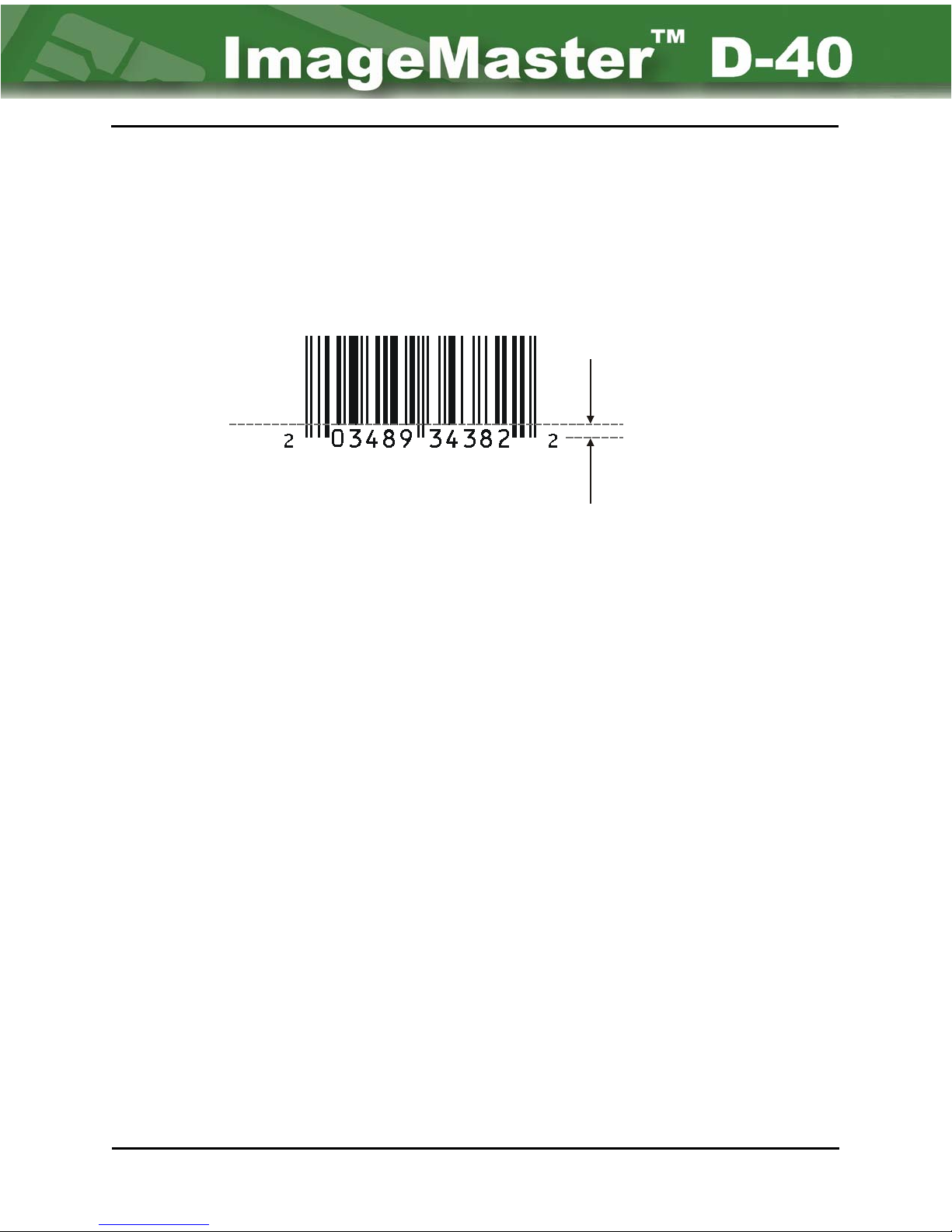
The “Guard Height” parameter is only available for UPC-A, NEW UPC-A, EAN 8, and EAN
13. “Guard Height” refers to the height of the guard lines. Guard lines are the portions of the
barcode that extends below and into the number field. (See Figure 4-14.) This parameter
allows the user to adjust and customize the height.
Lines
Barcode
Guard Height
Guard
Lines
Figure 4-14 Guard Height Parameter
4.7.5: Ratio
“Ratio” is the width of a wide line vs. the width of a thin line. (The “Ratio” parameter is not
available for UPC-A, or NEW UPC-A.)
4.7.6: Density
“Density” is the parameter that controls the width of a thin line. Each bar can be one of four
possible thickness, varying from 1 module to 4 modules.
4.7.7: Gap
“Gap” is the parameter that controls the space between lines. Each space can one be of four
possible thickness, varying from 1 module to 4 modules.
4.7.8: Orientation
The “Orientation” parameter allows the D-40 printer to print the barcode in any of the four
area directions around the X and Y Coordinates. These are: horizontal, vertical, reverse
horizontal, and reverse vertical. (It should be understood that some barcodes cannot be read
backwards or upside down.)
Creating Layouts Chapter 4 Page 16
Page 36

D-40 Operation Manual 4-17
4.7.9: Human Readable
The “Human Readable” parameter refers to the number field that is apart of the barcode.
Certain barcodes such as Codabar, Code 2 of 5, and Code 128 do not contain this option
(or field). If “No” is selected, the menu goes to the “Transfer” parameter. If “Yes” is selected,
the user will be asked for a font name to be associated with the field.
4.7.10: Card Side
The “Card Side” parameter specifies what side of the card the printing is to occur on. The
options are TOP or BOTTOM.
4.7.11: Transfer
The “Transfer” parameter is used to identify a field as the source of data to be transferred or the
destination to which data is transferred. However, in order to transfer data, the source must be
identified first. Regardless, when a source or destination is chosen, another sub-menu will
appear. (Refer to Figure 4-9, and Figure 4-10.) The name of the source and destination must
be 4 characters long, and must match in order for the data to be sent from the source to the
destination. If no data is to be transferred, however, this parameter can be turned off.
4.7.11.a: Source & Destination Id
This parameter is used to identify the field as either the source or destination of transferred
data. Its naming convention, however, will only allow a maximum of four characters. The
destination name must match the source name.
4.7.11.b: Transfer Type
This parameter refers to the data associated with the field(s) to be transferred. The “Normal”
selection means that the data field is transferred as it has been entered (verbatim). The
“Name” selection means that first and last names are reversed when this option is selected.
4.7.11.c. Strip Spaces
This parameter designates whether spaces in the data are removed (stripped away) during
the data transfer.
4.7.12. Accept
The “Accept” parameter designates how data will be “accepted” by the field. Data is “Fixed”,
“Variable”, or from a Host. (Refer to Figure 4-11.)
Chapter 4 Page 17 Creating Layouts
Page 37

4-18 NBS Technologies Inc.
If the source is “Fixed”, the exact text will be stored along with the layout in the D-40. This text
is entered after the “Fixed Text” prompt as the field is created. Once stored, it can only be
changed by “editing” the layout.
If the choice is “Variable”, the field can only be filled in using keyboard data entry at the time
of printing. However, the “Variable” fields are only temporarily stored in the system’s RAM
and require new data be entered for each card.
If “Host” is chosen, the field is populated with data from a host computer connected to an
identified communication port. However, the host protocol (as well as other communication
settings) must be identified and set under the “Communication” options prior to usage.
4.7.12.a: Pad Character
“Pad characters” are the characters used to fill in the maximum character locations when the
data entered does not meet the maximum size of the field. Choices for this parameter are
either “None” or “Spaces”.
4.7.12.b: Auto Advance
The “Auto advance” parameter refers to moving the cursor to the next field automatically
when data is typed in at the time of card production, rather than having to manually depress
the entry key to do the same thing. When enabled, the auto advancement only takes place
after the maximum character amount for the field is reached. Choices for this parameter are
either “No” or “Yes”.
4.7.12.c: Prompt
This parameter allows entry of up to 35 characters of instructions or other pertinent
information that will appear in the prompt field and guide the operator’s entry of data.
4.7.12.d: Min Characters
This parameter sets the minimum number of characters allowed in a field.
4.7.12.e: Max Characters
The maximum number of characters allowed in a field, affecting the size of the field. The
maximum number will influence (or be influenced by) the point size of the font used.
Creating Layouts Chapter 4 Page 18
Page 38

D-40 Operation Manual 4-19
4.7.12.f: Default Text
The “Default text” parameter allows entry of text that will be printed in the field if keyboard
entries are not made at the time of card production. (“Default Text” acts similar to “Fixed
Text”, but can be overridden by operator entry.) A maximum of 45 characters is permitted.
4.7.12.g: Allow
The “Allow” parameter is considered a validation mechanism. Its function is to minimize incorrect
keyboard entry by type of characters.
• If “Digits” is chosen, only digits (0-9) can be typed in the field.
• If “Alpha” is chosen, only letters (a-z) can be typed in the field.
• If “All” is chosen, not only can both letters and numbers can be typed in the field, but
all printable characters. This includes spaces, commas, symbols, etc.
The last two parameters are also dependent on what is selected for the “Allow” option. “Mod
10” and “Increment by” are only shown if “Digits” is selected.
4.7.12.g.1: MOD 10
The “Mod 10” option can only be used when “digits” have been selected for the “Allow”
option. This is because “Mod 10” stands for “Modulus 10 Check” – a validation test.
4.7.12.g.2: Increment by
The “Increment by” option also can only be used when “digits” have been selected for the
“Allow” option. The system can only increment the number by a single whole number
between 1 and 9.
4.7.12.h: Maximum Chars
This parameter sets the maximum number of characters allowed in a field, affecting the size
of the field. The maximum number will influence (or be influenced by) the point size of the
font used.
Chapter 4 Page 19 Creating Layouts
Page 39
4-20 NBS Technologies Inc.
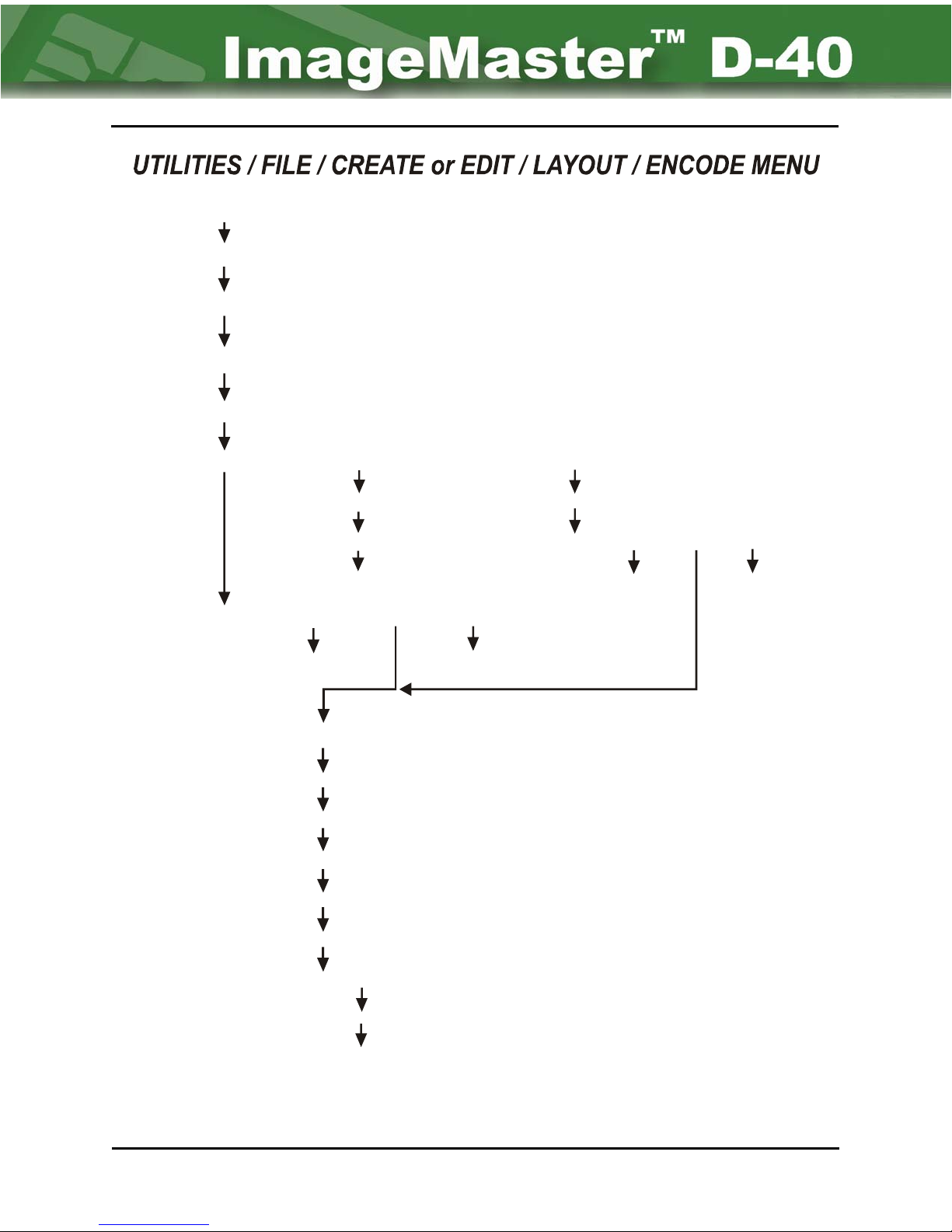
Type: Encode
Field Name - -
Tra ck 1 / Trac k 2 / Track 3
Start Position - - (Either 0 for “relative” - or 1 and above for “absolute”.)
Track Format - - ISO / Old Bally / New Bally
Encoding Dir - -
Transfer - -
Forward / Reverse
Off / Destination on / Source on
Destination ID
Tran sf er Ty pe - -
Strip Space - - Yes / No
Normal / Name
/ JIS / Custom
Source ID
Accept - -
Fixed / Variable / Host
Fixed Text Max. Char.
Accept - - Fixed / Variable / Host
Fixed Text Max. Char.
Pad Char. - - None / Space
Auto Advance - - No / Yes
Prompt - - (35 Char. Max)
Min. Characters
Max. Characters
Default Text - - (45 Char. max)
Allow - - Digits / Alpha / All
Mod 10 - - No / Yes
Increment by - (3 digit max)
Figure 4-15: Encode Field Type Overview
Creating Layouts Chapter 4 Page 20
Page 40

D-40 Operation Manual 4-21
4.8: UTILITY / FILE / CREATE or EDIT / LAYOUT
NCODE PARAMETERS)
(E
4.8.1: Field Name
The “Field Name” specifies which magnetic track is to be written to. The operator has a
choice between: Track 1, Track 2, and Track 3. This parameter is used in conjunction with
the “Track Format” parameter. However, special caution should be taken when designating
these two parameters, ensuring that they both match either industry standards or customer
requirements.
4.8.2: Start Position
“Starting Position” refers to the location of the first digit of the encoding field on a track.
There are two possible settings:
• “0" for Relative – The first digit is on the left margin of the encoding field, i.e., the
position is relative to the margin.
• “1" for Absolute – The first digit is off-set to the right of the left margin by spaces
equal to the number of digits entered, i.e., the encoding begins at an absolute number
of spaces from the left margin.
4.8.3: Track Format
Similar to “Name” in the Barcode option, “Field Name” allows the user the choice of identifying
the type of encoding format and its recording location on the magnetic strip. Any of these
formats may be selected by pressing the [SPACEBAR] until the desired barcode format is
displayed. The choices available:
• ISO
• Old Bally
• New Bally
• JIS
• Custom
4.8.4: Encoding Dir
The “Encoding Direction” specifies in which direction the magnet strip is to be written to. The
operator has a choice between either Forward or Reverse.
Chapter 4 Page 21 Creating Layouts
Page 41

4-22 NBS Technologies Inc.
4.8.5: Transfer
The “Transfer” parameter is used to identify a field as the source of data to be transferred or the
destination to which data is transferred. However, in order to transfer data, the source must be
identified first. Regardless, when a source or destination is chosen, another sub-menu will
appear. (Refer to Figure 4-9, and Figure 4-10.) The name of the source and destination must
be 4 characters long, and must match in order for the data to be sent from the source to the
destination. If no data is to be transferred, however, this parameter can be turned off.
4.8.5.a: Source & Destination id
This parameter is used to identify the field as either the source or destination of transferred
data. Its naming convention, however, will only allow a maximum of four characters. The
destination name must match the source name.
4.8.5.b: Transfer Type
This parameter refers to the data associated with the field/s to be transferred. The “Normal”
selection means that the data field is transferred as it has been entered (verbatim). The
“Name” selection means that first and last names are reversed when this option is selected.
4.8.5.c: Strip Spaces
This parameter designates whether spaces in the data are removed (stripped away) during
the data transfer.
4.8.6: Accept
The “Accept” parameter designates how data will be “accepted” by the field. Data is “Fixed”,
“Variable”, or from a Host. (Refer to Figure 4-11.)
If the source is “Fixed”, the exact text will be stored along with the layout in the unit. This text
is entered after the “Fixed Text” prompt as the field is created. Once stored, it can only be
changed by “editing” the layout.
If the choice is “Variable”, the field can only be filled in using keyboard data entry at the time
of printing. However, the “Variable” fields are only temporarily stored in the system’s Ram
and require new data be entered for each card.
If “Host” is chosen, the field is populated with data from a host computer connected to an
identified communication port. However, the host protocol (as well as other communication
settings) must be identified and set under the “Communication’s” options prior to usage.
Creating Layouts Chapter 4 Page 22
Page 42

D-40 Operation Manual 4-23
4.8.6.a: Pad Character
“Pad characters” are the characters used to fill in the maximum character locations when the
data entered does not meet the maximum size of the field. Choices for this parameter are
either “None” or “Spaces”.
4.8.6.b: Auto Advance
The “Auto advance” parameter refers to moving the cursor to the next field automatically
when data is typed in at the time of card production, rather than having to manually depress
the entry key to do the same thing. When enabled, the auto advancement only takes place
after the maximum character amount for the field is reached. Choices for this parameter are
either “No” or “Yes”.
4.8.6.c: Prompt
This parameter allows entry of up to 35 characters of instructions or other pertinent
information that will appear in the prompt field and guide the operator’s entry of data.
4.8.6.d: Min Characters
This parameter sets the minimum number of characters allowed in a field.
4.8.6.e: Max Characters
This parameter sets the maximum number of characters allowed in a field, affecting the size
of the field. The maximum number will influence (or be influenced by) the point size of the
font used.
4.8.6.f: Default Text
The “Default text” parameter allows entry of text that will be printed in the field if keyboard
entries are not made at the time of card production. (“Default Text” acts similar to “Fixed
Text”, but can be overridden by operator entry.) A maximum of 45 characters is permitted.
4.8.6.g: Allow
The “Allow” parameter is considered a validation mechanism. Its function is to minimize
incorrect keyboard entry by type of characters.
• If “Digits” is chosen, only digits (0-9) can be typed in the field.
• If “Alpha” is chosen, only letters (a-z) can be typed in the field.
• If “All” is chosen, not only can both letters and numbers can be typed in the field, but
any printable character. This includes spaces, commas, symbols, etc.
Chapter 4 Page 23 Creating Layouts
Page 43

4-24 NBS Technologies Inc.
The last two parameters are also dependent on what is selected for the “Allow” option. “Mod
10” and “Increment by” are only shown if “Digits” is selected.
4.8.g.1: Mod 10
The “Mod 10” option can only be used when “digits” have been selected for the “Allow”
option. This is because “Mod 10” stands for “Modulus 10 Check”–a validation test.
4.8.g.2: Increment by
The “Increment by” option also can only be used when “digits” have been selected for the
“Allow” option. The system can only increment the number by a single whole number
between 1 and 9.
4.9: Utility / File / Create or Edit Layout (IMAGE
PARAMETERS)
4.9.1: Accept from
This parameter designates from what source the image file is to be retrieved from. There are
only two options: retrieve the “Stored File” from memory of the D-40 printer, or retrieve the file
from the “Host”.
4.9.2: Image Name
This parameter designates the exact name of the file to be retrieved form a list of files.
4.9.3: X & Y Coordinates
The next two parameters – “X & Y coordinates” – work together to determine the starting points of
the field. They are referenced in relation to an imaginary point (origin) in the upper left hand corner
of the card. The placement of the field (along with font size and steps) affects the number of
characters, which may be embossed. The “X & Y coordinates” refers to its baseline position.
4.9.4: Rotation
The “Rotation” parameter allows the D-40 to print in any of the four orientations in reference to
the “X” location. These are: horizontal, vertical, reverse horizontal, and reverse vertical.
Creating Layouts Chapter 4 Page 24
Page 44
D-40 Operation Manual 4-25
4.9.5: Card Side
The “Card Side” parameter specifies what side of the card the printing is to occur on. The
options are Top or Bottom.
4.10: Utility / File / Copy & Delete Commands (For Layout,
Font, Image, Kanji, Firmware)
As stated previously, the “Copy” sub-menu allows for the copying of an existing card layout and
its renaming. (See Figure 4-16.) This is similar to the “Delete” sub-menu, which allows deletion
of an existing card layout from memory. (Refer to Figure 4-17.) These screens are self
explanatory and need no further clarification.
Enter
Enter
Please select a layout (etc.) to copy.
VISA MC AMEX DISCOVER
Type new layout (etc.) name: (16 characters)
Figure 4-16: Copy Layout Screens
Please select a layout to delete.
VISA MC AMEX DISCOVER
Delete file: (Name)
Are you sure?
Figure 4-17: Delete Layout Screens
4.11: UTILITY / FILE / DOWNLOAD & UPLOAD
COMMANDS (For Layout, Font, Image, Kanji,
Firmware)
The “Download” command is used to retrieve an existing file from the host computer, while
the “Upload” command is used to transfer a file to the host computer from the D-40 Printer.
These options are illustrated in Figure 4-18 and Figure 4-19. Both use an Xmodem*
application for the file transfer.
Chapter 4 Page 25 Creating Layouts
Page 45
4-26 NBS Technologies Inc.
Xmodem is a communication’s protocol that allows a file-transfer between a
computer and a host, utilizing a network. It uses blocks of 128bytes for the file,
NOTE:
NOTE:
and a single byte checksum (per block) for error correction. If an error is
encountered, the block is then re-sent. This protocol is supported under the
Hyper-term application using Windows XP.
The Dashboard application supplied with the D-40 Printer supports both uploading
and downloading of files over an Ethernet TCP/IP network. This is the preferred
method of file transfer(using Xmodem transfer protocol) if a network connection
is unavailable.
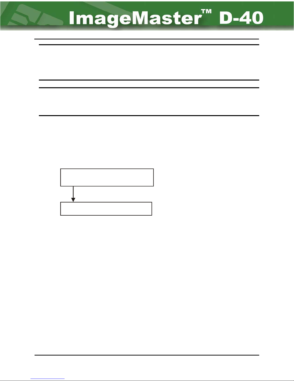
UTILITY / FILE / DOWNLOAD MENU
Xmodem Exit
Download file using Xmodem
Start up host Xmodem application
Figure 4-18: Download Menu Screens
Creating Layouts Chapter 4 Page 26
Page 46
D-40 Operation Manual 4-27
UTILITY / FILE / UPLOAD MENU
Layout Font Image Kanji Firmware All Exit
Upload existing layout (etc.)
Choose All Exit
Choose specific layout (etc.) to upload
Please select a layout (etc.) to upload
(List of file names)
Xmodem Exit
Upload file to host using Xmodem
Start up host modem application
Choose All Exit
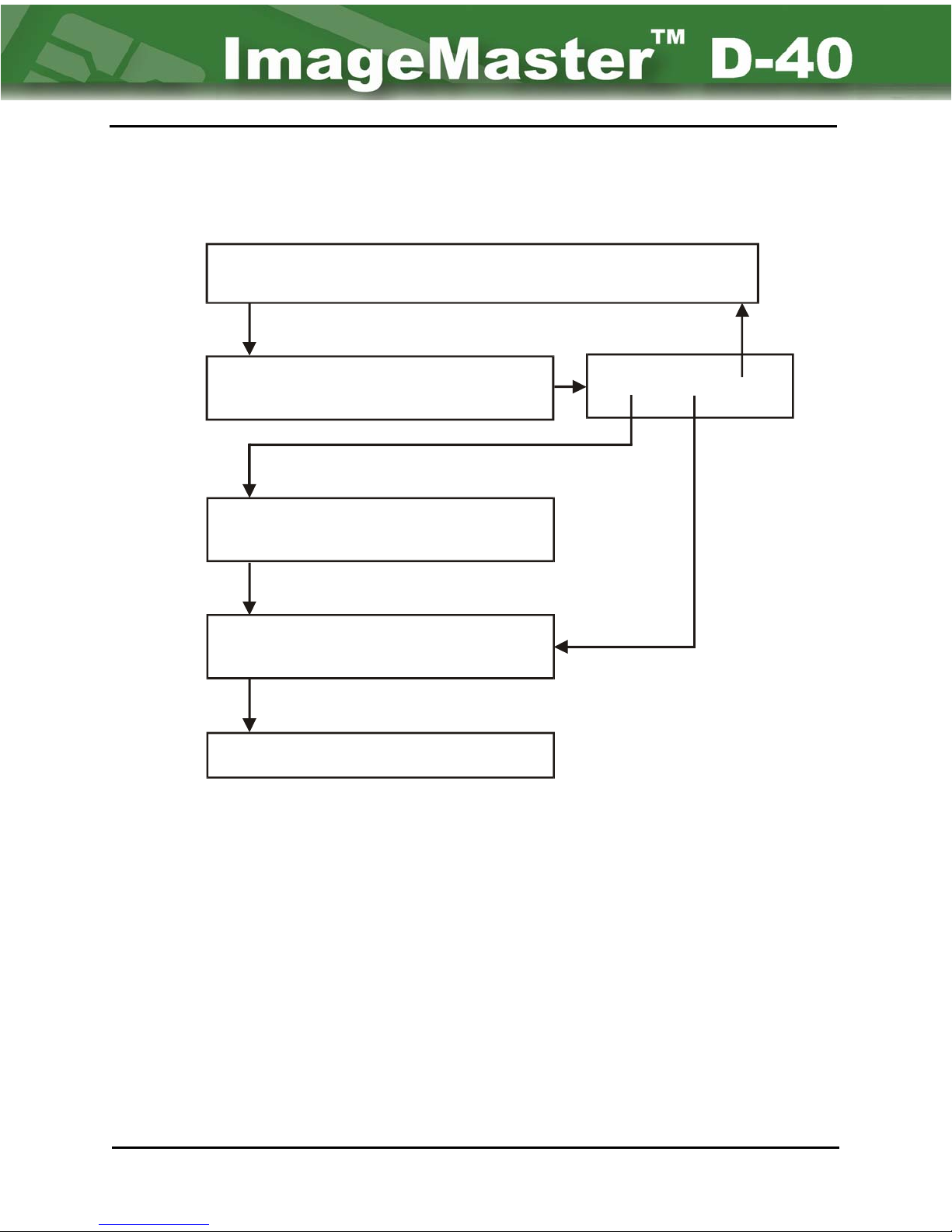
4.12: UTILITY / FILE / SELBOOT
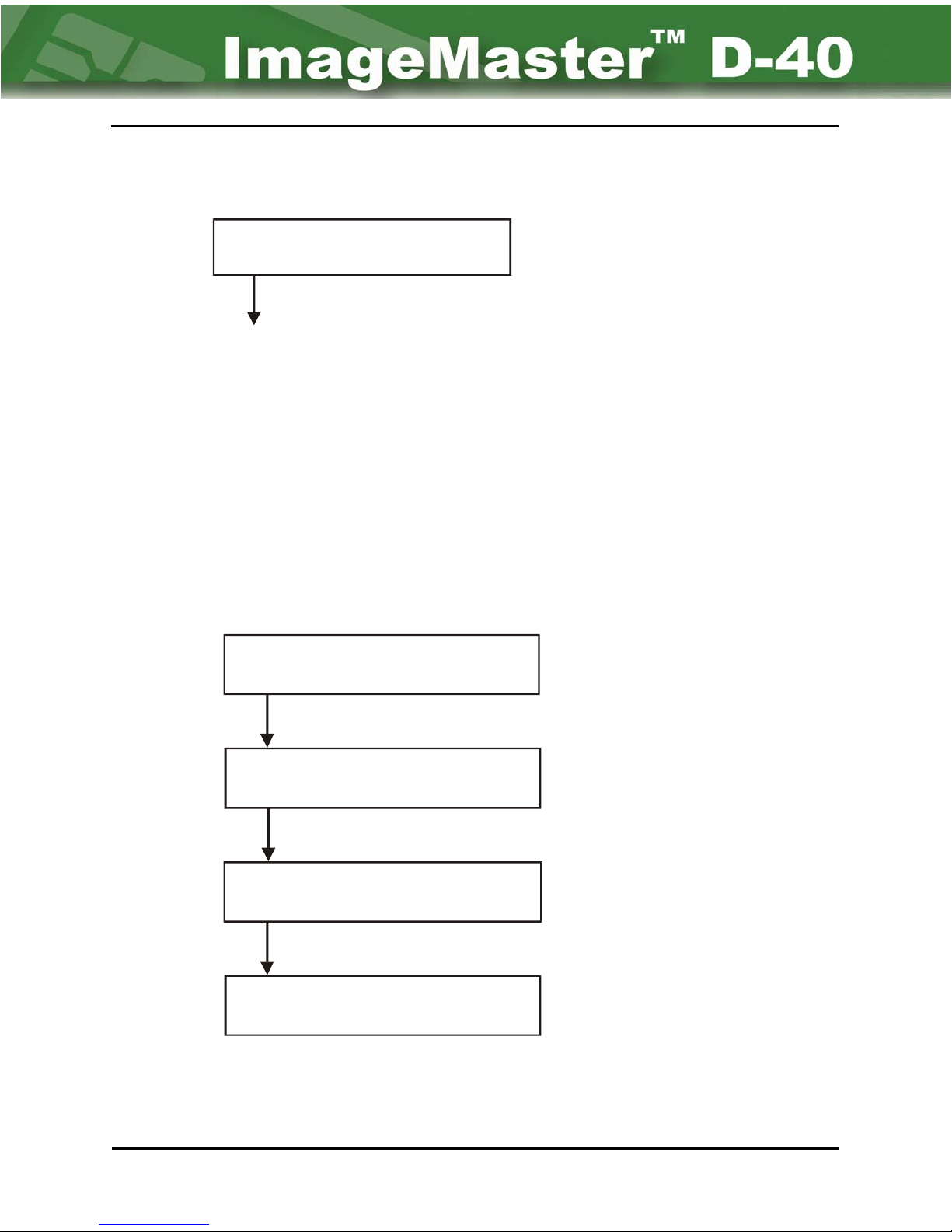
The “SelBoot” parameter specifies the boot file to be used the next time the D-40 printer is
either re-started or reset. The file selection is made from a list of choices displayed on the
LCD. (Refer to Figure 4 -20.) If the user has not chosen a boot file, then the D-40 will prompt
the operator to chose a file that the unit will boot from every time it powers up.
Chapter 4 Page 27 Creating Layouts
Figure 4-19: Upload Menu Screens
Page 47
4-28 NBS Technologies Inc.
UTILITY / FILE / SELBOOT MENU
Please select boot firmware file:
(List of file names)
Back to Utility Menu
Figure 4-20: SelBoot Menu Screens
4.13: UTILITY / FILE / STATUS
The “Status” is used to monitor the amount of Flash Memory available in the D-40. This
memory space is used to store layouts, fonts, images, and firmware files. (See Figure 4-21.)
UTILITY / FILE / STATUS
File System Status
Free space available........xxxxxxxxx
File System Status
Used space........xxxxxxxxx
File System Status
Total space available........xxxxxxxxx
File System Status
Total number of files
Creating Layouts Chapter 4 Page 28
Figure 4-21: Status Menu Screens
Page 48

D-40 Operation Manual 5-1
Chapter 5 - Operator Maintenance
A great aid in keeping the ImageMaster™ D-40 Printer functioning properly, is conducting
routine inspections and maintenance on the system. Dirt and other contaminants will not only
affect the quality of the cards produced, but also reduce the efficiency of the machine as well
as increasing the card rejection ratio.
This chapter contains a few helpful tips as well as a few maintenance measures for
maintaining the functionality of the machine. However, should any technical problems arise,
the user should contact their Authorized Dealer or NBS service representative for help.
5.1: General Cleaning
The cabinet should be wiped with a clean, damp cloth to remove any loose contaminants.
Never use soap and water to remove dirt. This can possibly leave a residue, creating
operational problems and aiding dirt to re-accumulate over time.
The interior of the cabinet should be inspected for shavings or other types of contaminants
(residue from card production). If found use a vacuum cleaner to remove them. If not
possible, then wipe away with a damp, clean cloth.
Primarily, most accumulations will be found in the area of the Encoder (Flipper) and rollers on
either side of the print head. Wipe all rubber rollers off with a lint free cloth saturated in
alcohol.
5.2: Cleaning The Print Head
Cleaning the Print Head is a service technician function and should not be attempted by
operators. An indication that a build-up of contaminants may be occurring is if unusual folds or
wrinkles appear on the foil as it is being taken up. These folds or wrinkles can be caused by
increased friction from the accumulation of contaminants on the head, pulling and distorting the
tape. If this occurs, contact your NBS or Authorized Dealer service technician.
5.3: Card Stock
The D-40 printer is capable of printing on a polished PVC card that is 0.030 inch thick. When
placing cards into the Input Hopper, be sure that the magnetic strip (if applicable) is orientated
correctly (face down and toward the rear of the machine).
Ensure that the cards are not “stuck” together. This is accomplished by rippling or fanning
the cards before they are stacked in the Input Hopper. The purpose of this is not only to
break apart any cards wedged together, but to reduce static electricity that causes attraction
between card surfaces. It also may remove some of the dust or shavings on the cards,
allowing them to feed more easily.
Chapter 5 Page 1 Operator Maintenance
Page 49
5-2 NBS Technologies Inc.
Card stock that is bowed or bent may also cause feed problems. Most likely they will cause a
“card jam”, where a card cannot move while being transported in the system. When this
problem occurs, the simplest solution is to open the cabinet and remove the distorted card.
However, if the card does not readily come out, do not force it out as it may damage the
system. This will require your service representative to investigate and remedy the problem.
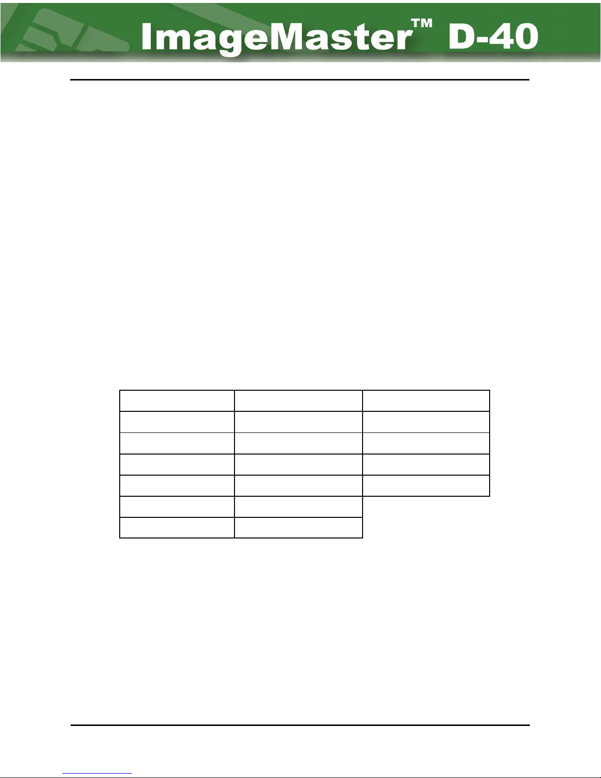
5.4: Ordering Consumable Supplies
Consumable Supplies are ordered by calling the Customer Service Department at 1-416-8408620 (globally), or 800-524-0419 (USA only).
Only the use of genuine NBS consumables can guaranty proper printer operation.
• Basic Blank card stock is available in either White or White with magnetic stripe.
White
White with Loco magnetic stripe
White with Hico magnetic strip
(Colors other than white are available on special order.)
• Printing foil is available in the following colors:
Gold Metallic Gold Burgundy
Silver Metallic Silver Orange
White Light Blue Brushed Silver
Dark Red Midnight Blue Yellow
Dark Blue Teal Scratch-off
Dark Green Purple
Black Red
• Cleaning tape is available using part number 5091.
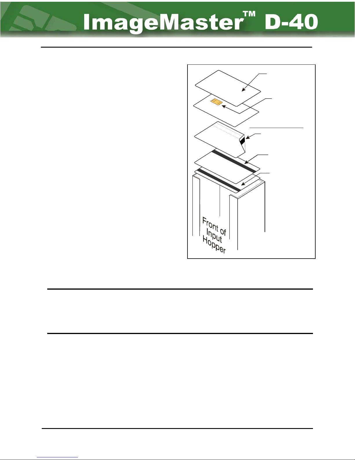
5.5: Loading Cards
A major function of the operator is the loading of blank cards and the removal of personalized
cards. Cards are loaded into the input hopper on the right side of the unit.
Operator Maintenance Chapter 5 Page 2
Page 50
D-40 Operation Manual 5-3
General rule:
5.5.1 Plain cards
Cards are normally placed so the front of the
card is facing up and the top of the card is at the
rear of the hopper.
Front up &
top to rear
Smart Card:
Chip Up &
to left
5.5.2 Magnetic Strip Cards
When loading magnetic strip cards, they are
normally placed with the mag strip down and
towards the rear of the hopper.
5.5.3 Smart Cards
Smart Cards are normally loaded with the top of
the card at rear of hopper with the front of the
card facing up which places the smartcard chip
towards left side of hopper.
Magnetic Stripe
ISO & JIS Type II-C:
Down & to rear
JIS Type II-A:
Up & to rear
JIS Type II-B:
Up & to front
Figure 5-1 Card Orientation
Never place fingers into the Hoppers when cards are being produced.
Always pause operation before adding or removing cards from the
! Caution:
Input or the Stacker hoppers. (Press “Wait” button on front panel).
Moving parts, in the base of the input and stacker hoppers, can cause
physical injury to fingers if care is not taken.
5.6: Unloading Cards
When cards are correctly personalized the are placed into the output Stacker on the left side of
the unit. If a card is rejected during processing it is allowed to fall into the reject area under the
output Stacker. The reject area holds about 15 cards. Monitor the reject area. Do not allow
cards to build up here as they could jam the stacking process.
Chapter 5 Page 3 Operator Maintenance
Page 51

5-4 NBS Technologies Inc.
5.7: Replacing Printing Ribbon
Removing Old Ribbon
1. Pause unit operation (Press WAIT button on control panel). Never insert fingers into an
operating unit.
2. Remove the retainer from each spool by turning retaining knob counter clockwise (Refer to
Figure 5-2.) .
3. Remove the full core from the take-up spool and discard. Remove the empty core from the
supply spool, and save for reuse.
Installing New Printing Ribbon
1. Mount the empty core, saved in step 3 above, to the take-up spool.
2. Mount the new ribbon on the supply spool so that it will uncoil from the top of roll in a counter
clockwise direction as shown in Figure 5-2.
3. Thread the ribbon as shown in Figure 5-2 below. Place tape around left side and under roller
1 — across and over roller 2 — down and under guide rod — under the print head — to left
outside of peel plate — left outside of roller 3 — and up to take-up spool. Tape the end of
the ribbon to the empty take-up core. Caution must be taken to assure that the ribbon is
mounted squarely, so that it will roll evenly as it is used.
4. Screw the retainers in place and tighten them so the cores do not slide on their respected
spools. Ensure that the pin in the take-up spool locks into the hole in the retainer plate and
that the screw is inserted into a notch in the cardboard core.
5. Once the ribbon is loaded, press [CTRL] + [W] to initiate movement. The take-up spool will
run until the [CTRL] + [W] keys are pressed again. Ensure the ribbon is winding correctly,
and that the ribbon moves freely and evenly.
Operator Maintenance Chapter 5 Page 4
Page 52
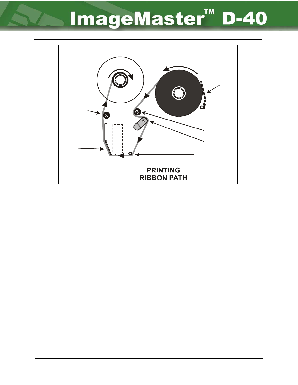
D-40 Operation Manual 5-5
P
TAKE -U
NEW ROLL
Low
Ribbon
Sensor
Roller 3
Peel
Plate
d
a
e
H
t
n
i
r
P
Figure 5-2 Printer Ribbon Path
Roller 1
Roller 2
Guide Rod
5.8 Replacing Cleaning Tape
Removing Old Tape
1. Pause unit operation (Press WAIT switch). Never place fingers into an operating unit.
2. Unscrew the retainer knob on the take-up spool by rotating it in a counter-clock wise
direction. Next, remove the retainer plate. (Refer to Figure 5-3.)
3. Slide the full core from the take-up spool and discard.
Installing New Tape
1. Unscrew the retainer knob and remove the retainer plate from the source spool. Next,
remove the empty core.
2. Mount the empty core on the take-up spool.
3. Unwind approximately 10” of tape from the new tape core.
4. While sliding the new tape core on the supply spool so that it will unwind in a clockwise
direction; thread the tape under the guide rod, then around the cleaning roller, and up to
the take-up spool core.
Chapter 5 Page 5 Operator Maintenance
Page 53
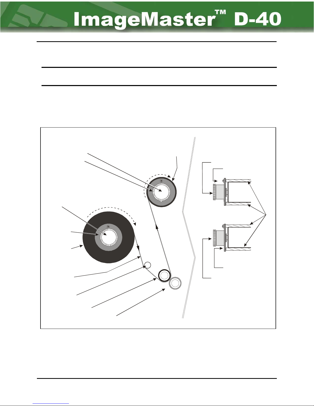
5-6 NBS Technologies Inc.
5. After fixing the tape in place, remount the retainer and tighten to prevent the core from
sliding.* Also, ensure that the screw is inserted into a notch on the cardboard core.
NOTE:
6. Press the [CTRL]+[K] keys to initiate the cleaning tape. It will continue to run until the
[CTRL]+[K] keys are pressed again. Ensure that there is no slippage and that the tape
moves freely and evenly. However, movement of the tape will be “strained” due to the
adhesive.
Retainer Knob
Retainer Plate
The take-up spool has a roll pin that must be inserted in the retainer plate when
mounting. This is added insurance that the core will not slide on the spool.
Front View
Side View
Take-U p Spo o l
Retainer Knob
Retainer Plate
Retainer
Knob
Spool Core
Retainer
Plate
Supply
Spool
Cleaning
Tape Path
Guide Bar
Cleaning Roller
Blue Card Cleaning Roller
Figure 5-3 Cleaning Tape Assembly
Retainer Plate
Retainer Knob
Operator Maintenance Chapter 5 Page 6
Page 54
D-40 Operation Manual 6-1
Chapter 6 - Error Messages
The left column (LCD Error Messages) displays the error messages that can appear in the
LCD Display during normal system operation. The right column defines the problem and
suggests possible causes and operator remedies. Any problem that an operator can not
solve or that obviously involves mechanical fixes, or hardware replacement should be referred
to qualified service technician - either NBS, authorized Dealer, or authorized Service Provider
technician. Unauthorized repairs performed by un-trained technicians can void your warranty.
Error Messages (Displayed on ImageMaster™ D-40 Printer)
LCD Error
Message
Broken or
missing foil
Card Pick Error
Card stuck in
transport
Description
Problem: No detected motion of Printer Foil.
Cause: Printer is out of foil, the foil is broken or not properly
threaded, Foil Motor bad, or sensor is bad.
Operator Replace foil or fix broken foil or re-thread.
Action: For mechanical problems contact NBS Service Rep.
Problem: Hopper detected as being empty while trying to pick card.
Cause: Hopper empty, or bad sensor
Operator Re-load Hopper
Action: For mechanical problems contact NBS Service Rep.
Problem: Card detected in transport after flush attempt.
Cause: Bent card, bad sensor, transport Motor bad, a “jumped”
drive belt, or “Flush Speed” at wrong setting.
Operator Remove bent or jammed card and try again. Check
Action: “Flush Speed” setting if allowed. For mechanical
problems contact NBS Service Rep.
Problem: Problem occurred during cleaning process.
Cause: Low or broken cleaning tape, bad sensor, or bad
Cleaning Timeout
Operator Replace or fix cleaning foil.
Action: For mechanical problems contact NBS Service Rep.
Problem: Start sentinel not found at correct position on track n,
Encoding Position
Error n
Chapter 6 Page 1 Error Messages
Cause: Bent card, Magnetic Encoder Head possibly out of
cleaning tape drive motor.
where n is number of encoding track with problem.
alignment, start sentinel has wrong setting (check
“Encode Start”, “Encode W/R Delay”, “Wheel Count to
Edge”, and “Start Check Tolerance” parameters).
Page 55
6-2 NBS Technologies Inc.
LCD Error
Message
Encoding Position
Error n (con’t)
Encoding Timeout
Flipper Jam
Foil Jam
Description
Operator Remove bent card try again. Check settings and
Action: correct if needed. For mechanical problems contact NBS
Service Rep.
Problem: Encoded magnetic stripe data cannot be verified.
Cause: Bent card, not using magnetic cards, damaged card, or
transport problem.
Operator Remove bent/jammed card. Make sure Magnetic
Action: cards are in use. For mechanical problems contact
NBS Service Rep.
Problem: Flipper mechanism did not move when activated.
Cause: Jammed card (possibly due to wrong “Handoff Position”
or “Flip Count” setting), bad Flipper motor,
Operator Remove jammed card & check settings
Action: For mechanical problems contact NBS Service Rep.
Problem: Detection of motion of Printer Foil when there shouldn’t be.
Cause: Foil caught in transport system or bad sensor.
Operator Reposition Foil
Action: For mechanical problems contact NBS Service Rep.
Please Calibrate
Printer
Print Head data
under run
Print Head too hot
Problem: Printer requires calibration.
Cause: Printer not calibrated
Operator Go to < UTILITY / SYSTEM / TEST / CAL > to
Action: run a card for calibration.
Problem: Transport speed is too fast for printer causing a data
under-run to occur.
Cause: “Print Speed” at wrong setting, or transport motor
defective.
Operator Correct Print Speed setting
Action: For mechanical problems contact NBS Service Rep.
Problem: Print Head temperature is too high.
Cause: “Head Resistance” setting wrong, or bad Print Head
(either internal thermistor or Print Head itself bad).
Operator Let unit cool down. If password allows, check and
Action: correct “Head resistance” setting. For mechanical
problems contact NBS Service Rep.
Error Messages Chapter 6 Page 2
Page 56
D-40 Operation Manual 6-3
LCD Error
Message
Print Head
Watchdog Error
Printing Timeout
Print Ramp Error
Description
Problem: Occurs when transport is jammed while Print Head is
energized.
Cause: A card jam or a jammed drive belt.
Operator Remove jammed card. For mechanical problems
Action: contact NBS Service Rep.
Problem: Problem occurred during printing process.
Cause: Jammed card, bad Print Head Motor, or bad Print Head.
Operator Remove jammed card. For mechanical problems
Action: contact NBS Service Rep.
Problem: Print speed still changing while trying to print.
Cause: “Head Down Count” needs to be increased.
Operator If password allows, check and correct “Head Down
Action:
Problem: Communications error between Main Logic Board and
Count” as required.
Servo Board.
Servo Comm
Error
Stacker or Picker
Jam
Stacker or Picker
Timeout
Cause: Bad or loose cable, bad Servo Board, bad Main Logic
Board.
Operator For mechanical problems contact NBS Service Rep.
Action:
Problem: Picker or Stacker motion not detected.
Cause: Card jammed in the transport system, or a Bad motor, or
a bad sensor.
Operator Remove jammed card(s). For mechanical problems
Action: contact NBS Service Rep.
Problem: Card did not try to move when trying to pick or stack.
Cause: Jammed card, bad sensor, or empty Hopper (for Picker).
Operator If Hopper is empty load more blank cards, remove
Action:
jammed card(s). For mechanical problems contact
NBS Service Rep.
Chapter 6 Page 3 Error Messages
Page 57
6-4 NBS Technologies Inc.
LCD Error
Message
Track Encoding
Error N
Transport Jam
Description
Problem: Error detected while verifying magnetically encoded card
on track n, where n is the number of the encoding track
reporting error.
Cause: Bad card, Magnetic Encoder Head possibly out of
alignment, start sentinel has wrong setting (check
“Encode Start”, “Encode W/R Delay”, “Wheel Count to
Edge”, and “Start Check Tolerance” parameters).
Operator Remove card and try again, check settings
Action: For mechanical problems contact NBS Service Rep.
Problem: Transport servo reports a jammed condition.
Cause: Jammed card sometimes occurs when there is
resistance to running the transport, also can occur if
“Max Speed” set too high (typically above 65), or a
jammed drive belt.
Operator Remove jammed card, check and correct settings.
Action: For mechanical problems contact NBS Service Rep.
Error Messages Chapter 6 Page 4
Page 58
D-40 Operation Manual RH-1
Revision History
Page # Rev Date Description/Change
Cover — 15 May 08 Initial release - Binder Cover
Spine — 15 May 08
Forward
Title Pg — 15 May 08 Initial release
Inside — 15 May 08 Initial release
i — 15 May 08 Table of Contents - Initial release
ii — 15 May 08 Table of Illustrations - Initial release
Chapter 1 - Introduction
1-1 — 15 May 08 Initial release
1-2 — 15 May 08 Initial release
1-3 — 15 May 08 Initial release
1-4 — 15 May 08 Initial release
1-5 — 15 May 08 Initial release
1-6 — 15 May 08 Initial release
Chapter 2 - Main Menu - Basic Functioning
2-1 — 15 May 08 Initial release
2-2 — 15 May 08 Initial release
2-3 — 15 May 08 Initial release
2-4 — 15 May 08 Initial release
2-5 — 15 May 08 Initial release
2-6 — 15 May 08 Initial release
Chapter 3 - Printing Cards
3-1 — 15 May 08 Initial release
3-2 — 15 May 08 Initial release
3-3 — 15 May 08 Initial release
3-4 — 15 May 08 Initial release
Chapter 4 - Creating Layouts
4-1 — 15 May 08 Initial release
4-2 — 15 May 08 Initial release
4-3 — 15 May 08 Initial release
4-4 — 15 May 08 Initial release
4-5 — 15 May 08 Initial release
4-6 — 15 May 08 Initial release
4-7 — 15 May 08 Initial release
4-8 — 15 May 08 Initial release
Initial release - Binder Spine
Chapter RH Page 1 Revision History
Page 59
RH-2 NBS Technologies Inc.
Page # Rev Date Description/Change
4-9 — 15 May 08 Initial release
4-10 — 15 May 08 Initial release
4-11 — 15 May 08 Initial release
4-12 — 15 May 08 Initial release
4-13 — 15 May 08 Initial release
4-14 — 15 May 08 Initial release
4-15 — 15 May 08 Initial release
4-16 — 15 May 08 Initial release
4-17 — 15 May 08 Initial release
4-18 — 15 May 08 Initial release
4-19 — 15 May 08 Initial release
4-20 — 15 May 08 Initial release
4-21 — 15 May 08 Initial release
4-22 — 15 May 08 Initial release
4-23 — 15 May 08 Initial release
4-24 — 15 May 08 Initial release
4-25 — 15 May 08 Initial release
4-26 — 15 May 08 Initial release
4-27 — 15 May 08 Initial release
4-28 — 15 May 08 Initial release
Chapter 5 - Operator Maintenance
5-1 — 15 May 08 Initial release
5-2 — 15 May 08 Initial release
5-3 — 15 May 08 Initial release
5-4 — 15 May 08 Initial release
5-5 — 15 May 08 Initial release
5-6 — 15 May 08 Initial release
Chapter 6 - Error Messages
6-1 — 15 May 08 Initial release
6-2 — 15 May 08 Initial release
6-3 — 15 May 08 Initial release
6-4 — 15 May 08 Initial release
Revision History
RH-1 — 15 May 08 Initial release
RH-2 — 15 May 08 Initial release
Critique Form
Form — 15 May 08 Initial release
Revision History Chapter RH Page 2
Page 60
ImageMaster™ D-40 Operation Guide
NBS -1020-080205
Critique Form
P/N 13456
Name: Title:
Company:
Address:
City: State/Prov: ZIP/Post Code:
Phone: Email: Fax:
Every effort was made to document the operation of the ImageMaster™ D-40 Unit in a manner to simplify
your job, yet keep you fully informed. If we missed the mark, we want to know.
Was the Manual: YES NO
Readable?
Understandable?
Organized?
Illustrated Well?
Detailed Enough?
Comments: Please include page numbers, figure numbers and the like for our reference.
Complete?
Use reverse or another page(s) for added space. Thank you.
Forward completed form to: NBS Technologies Inc. Email: [email protected]
Technical Writer Fax: 201-845-3337 (USA)
70 Eisenhower Drive
Paramus, NJ, USA 07652
 Loading...