

NBE Scotte 16kw, Scotte 24kw, Scotte 30kw, Opop 430, Opop 460 Installation And Operating Manual
...
Scotte/Opop
Installation and operating
Manual 16, 24 & 30kw
NORDIC BIO ENERGY LTD
Pellets Systems

CONTENTS
Section 1 ……….Legal requirements
• Planning and building control page 2
• Installation expertise page 2
Section 2 ……….Specification
• Description of Boiler & Manufacturers plate page 3
• Dimensions page 3 + 4
• Wiring diagram page 4
Section 3 ……….Assembly
• Fitting the burner into the boiler page 5
• Feed screw and pellet silo assembly page 5 + 6
Section 4 ……….Installation
• Boiler connection page 7
• Flue pipe connection page 7
Section 5 ……….Operating the burner
• First time start up page 8
• Adjusting the burner page 8
• Main menu on controller page 9
• Secondary menu on controller page 10
• Symbols and functions on controller page 10
Section 6 ……….Maintenance
• Cleaning the burner page 11
• Troubleshooting page 12
• Installation Examples page 13
• Health and Safety page 14
• Quick start guide page 15
Page 1
SECTION 1

Planning requirements.
If you are thinking of making any changes to your property, including installing a
form of renewable energy, you must apply to the Building Control Office at your
local council for approval.
Planning permission may or may not be required, depending on such factors as:
location, individual planning department, nature of scheme, neighbors' opinions,
visual impact and proximity to public through roads.
Before beginning any work we recommend that you contact your local planning
department to determine whether planning permission is required.
Building regulations.
- Any installation of a heating appliance, or modification to a chimney such as
relining, has to be carried out in accordance with. Building Regulations – Republic
of Ireland Part F – Ventilation Part J – Heat Producing Appliances (Article 41 in
N.Ireland Part J in England and Wales and F in Scotland). Building Control
Consent might also be needed for such work unless the work is carried out by a
qualified person as stated below. We recommend that all installation or design is
completed in accordance with British Standards, including BS 5410 , BS 4543, BS
4876, BS 1181 and BS 715.
Installer expertise.
All installation work should be undertaken by a person who is a member of an
approved competent person scheme as outlined in the COMPETENT PERSON
SELF-CERTIFICATION SCHEMES IN 2003 which can be found at.
http://www.odpm.gov.uk/index.asp?id=1131139
All appliances must be commissioned and failure to do so will
invalidate the
boiler/burner warranty.
Page 2

SECTION 2
Description of Boiler.
1 Supply to radiators, hot water tank etc.
2 Flue pipe/chimney connection.
3 Return from the radiators, hot
water tank etc
4 Thermostat pocket .
5 Emptying and filling of water to
the system.
Manufacturers plate and serial number.
Dimensions of boiler.
Opop boilers: table 1
Model number: 418 430 460 4120
Power kw 18 30 40 – 60 80 - 120
Height mm 865 865 1005 1305
Width mm 386 490 800 1000
Depth mm 533 533 720 920
Flue mm 130 145 160 180
Water content litres 26 35 56 105
Weight kg 160 200 245 335
Connections 1 ¼” 1 ¼” 1 ½” 2”
Page 3
Burner/ boiler type. Scotte / OPOP
Output 16/24/30 kW
Classification EN 303-5 3
Test pressure 4.0 Bar
Max. operational pressure 2.5 Bar
Water content 26 litres
Boiler weight 160 kg
Exit gas temperature, nominal load 115°C
Exit gas temperature, low load 66°C
Flue gas mass flow rate, nominal
load
37.7 kg/h
Flue gas mass flow rate, low load 18 kg/h
Waterside resistance, delta T = 20 °K 1.37 mbar
Waterside resistance, delta T = 10 °K 5.39 mbar
Operating temperature min. 35ûC
Max. temperature 90ûC
Efficiency 93.3 %
Power consumption 220 V
35 Watts
Manufacturer: NBE
Tel.:
DK 9830 Tårs
0045-96892630
Serial Number
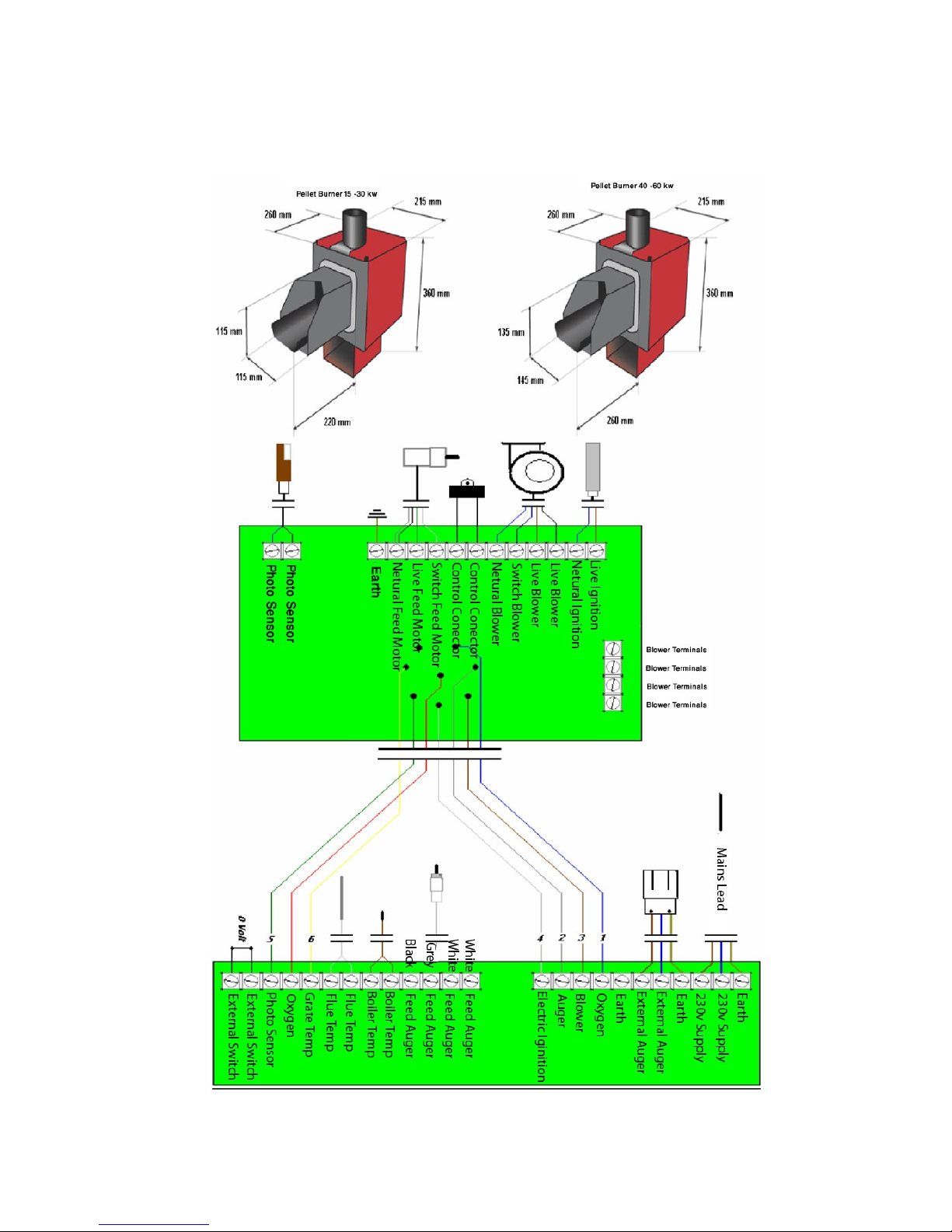
Dimensions of burner and wiring diagram.
Page 4

Section 3
Assembly.
Fitting the burner unit.
1. seal with fire rope or heat resistant gasket sealer to the boiler via the
square hole located on side of boiler (left or right depending on
requirement).
2. mount the burner unit into flange and secure locking bolts
Fitting the feed screw.
1. fit one end of the thermoplastic hose to the top of the inlet tube on the
burner unit, and the other end of the thermoplastic hose to the outlet of
the feed screw.
2. mount the feed screw over the burner so the pellets can fall into the
burner effortlessly. The more the feed screw is mounted at an incline, the
less pellets it releases.
- adjust the control system according to the angle of incline. (see section 5,
operating the burner)
3. ensure the thermoplastic hose is angled enough so the pellets end up in
the burner, shorten the hose if needed.
Page 5

Pellet silo assembly.
The pellet silo…..
As the pellets that you put into the silo contain dust, you should empty the silo
completely from time to time. The more dust that is in the silo, the less pellets
the feed screw will release and the boiler will become unadjusted, leading to
inefficiency and possible breakdown.
How often the silo needs emptying completely, depends on the design of the silo
and the quality of the pellet fuel used.
Page 6

Section 4
Installation.
Power supply and connection.
230 volts 50Hz 10 Amp 60 Watts
Control is supplied via a priming circuit breaker,(high limit safety cutout stat)
which is mounted on the rear of the boiler (item 4, page 3). The temperature
sensor is mounted in the same immersion pocket as the priming circuit breaker or
a suitable place where the boiler temperature can be measured. Mount the power
to the control system via the priming circuit breaker so that the power is broken if
the temperature of the boiler exceeds 95 degrees in the event of a fault.
Flue pipe and chimney connections.
Use the correct flue size for boiler model (table 1, page 3).
Ensure adequate height of chimney to gain satisfactory draw and to prevent back
draft. A suitable cowl/rain cap/anti back draft must be fitted.
We recommend that a draft stabilizer is always mounted to the chimney.
The vent pipe should not be greater than 1 metre in length and should be
equipped with an access door.
The flue pressure of the chimney should be a minimum of 10 PA and be stable. A
flue fan may be required to assist the draft and secure stability.
Upon condensation of flue gases in the flue, a condensation trap should be
installed, or the valve in the rear flue of the boiler be opened, so that the flue gas
temperature is increased.
Page 7

Section 5
Starting the unit for the first time.
1. check all connections on burner, boiler, feed screw, flue, chimney and
power supply.
2. ensure that there are pellets at the inlet of the feed screw in the pellet
silo.
3. activate the forced feed operation by pressing the UP button on the
controller for 10 seconds and turn the mains power on at the same time.
4. when the feed screw has filled with pellets and they are falling into the
burner, turn the power off at mains.
5. The burner is started by switching the mains power on again. The control
box can be started/stopped by pressing the on/off button for 8 seconds.
6. The alarm is cancelled by pressing the DOWN button 2 times within 8
seconds.
To obtain the optimum efficiency from the burner and boiler, correct
adjustment is essential.
Please refer to section 5 on adjusting the burner and section 6 on
cleaning the burner.
Adjusting the burner.
For first time start up, refer to quick start guide on page 15.
The outputs for high and low loads are run by the control system in a 100 step
modulation and the changes between the different steps are made automatically.
Feed adjustments for high and low loads.
Wood pellets can vary (dust, pellet length etc.) so correct adjustment for fuel
economy and boiler efficiency are essential. The feed screw will supply the pellets
differently and will have an influence on the burn quality. It is necessary to open
the doors to the burner and look at the flame.
If the flame is fat – dark, possibly with black points, or the ash is black with
black pellets, fewer pellets are needed. Reduce steps 2 and 3 in the main menu.
If the flame is thin – little flame and like a sparkler, or the ash is light grey,
more pellets are needed. Increase steps 2 and 3 in the main menu.
* Correct burning adjustments normally produce a dark grey ash. *
The burner is intended for wood pellets between 6-8mm diameter.
If you are in any doubt then subscribe to a service contract. For further
information visit : www.nordjysk-bioenergi.dk
Page 8

Main menu on controller.
In order to adjust the burner press the SET button on the controller and
you will gain access to the main menu use
There are four adjustment options in this main menu.
1. Boiler temperature: *factory settings 60 degrees*
press the UP or DOWN buttons to reach the required
water temperature.
2. Feed screw in low load: * factory settings 5.6 *
press the UP or DOWN buttons to adjust the quantity
of pellets that corresponds to the blower speed. It is
important that this adjustment is correct in relation to
the speed of the blower. In the event of an incorrect
adjustment, the boiler will not run as economically and
there will also be the risk of a breakdown.
3. Feed screw in high load: * factory settings 33.6*
press the UP or DOWN buttons to adjust the quantity
of pellets that corresponds to the blower speed. It is
important that this adjustment is correct in relation to
the speed of the blower. In the event of an incorrect
adjustment, the boiler will not run as economically and
there will also be the risk of a breakdown.
4. Feed screw in pause firing: * factory settings 16.0*
pause firing enables the burner to keep lit and not to
have to use the electronic ignition every time more pellets
are required. Press the UP or DOWN buttons to adjust
the quantity of pellets the burner will use during pause
firing. Set as low as possible without the burner going out.
The burner fires every 5 minutes.
PLEASE USE PELLET TABLES TO SET
ABOVE MENUS 2,3,4

Secondary menu on controller.
To gain access to the secondary menu press and hold the SET button for
6 seconds.
A1.......The amount of fuel for stoking up at start Standard 32 sec.
A2.......Ignition Time Standard 10 min.
A3.......The effect of the electric ignition Standard 70 %.
A4.......Value photo sensor shall exceed before there is fire Standard 10 Lx
A5.......Total ignitions time 0000 H
A6.......Times the ignitions has ignited 0000 T
A7.......Blower at ignition Standard 15 %
B1……Amount of time the burner is allowed to be in pause firing Standard 0 min
B2……Fan in pause firing Standard 15 %.
B3……Start after pause, degrees below boiler setpoint Standard 5 C
B4……Time of blowing when turning to OFF Standard 5 min
C1……Oxygen control Standard 0 ( OFF )
C2……Calibrating sensor 0
C3……Time with low O2 before stopping pellets Standard 30 min
D1.......Times of starts each day Standard 0 x
D2.......Max running time on each start Standard 60 min.
D3.......First start 00.00 H
D4.......Clock, to be adjusted by user 00.00 H
E1…....Cleaning interval Standard 10 min.
E2........Cleaning time Standard 4 sec
E3…....Cleaning power Standard 30 %.
E4…....Minimum power on burner Standard 10 %.
E5........Maximum power on burner Standard 100 %.
E6........Sommer time, ( low output and more temp. Diff. ) Standard 0 ( OFF )
E7........Temperature difference over setpoint Standard 10 C
Off 2 power of burner off 1 is the watch off 3 internal switch
Other functions on the controller.
Forced feed screw operation – to start hold the UP button when switching on.
To stop press the DOWN button.
Shift between temperature and oxygen displays and smoke temperature –
press DOWN one time (only when connecting the oxygen program).

Section 6
Cleaning the burner.
Switch off the control system by pressing the DOWN button for 5 seconds.
Wait for approximately 5 minutes to allow the burner to cool down. When it
has cooled down completely it is ready for cleaning. Take the connector off
the burner, remove the shield and down pipe, and unscrew the burner unit off
the boiler. The parts can now be worked with for cleaning.
To ensure best boiler operation,
cleaning should be done frequently.
This guarantees the best fuel
efficiency. The better the boiler is
set up the longer the intervals
between cleaning.
The boiler …..
The boiler should be emptied from
ash and all of the surfaces should be
brushed in order to remove soot
particles. Pay particular attention to
ash in the exhaust deflector and the
flue pipe. The flue pipe does NOT
clean itself. You must do this yourself.
An old vacuum cleaner is the best
method for this.
The burner head …..
Remove the ash and any cinders from the unit.
Remove any pellet remains under the unit. Dry off the flame indicator.
Ensure that there is nothing in the blower.
Starting up after cleaning ….
Reassemble the burner and fit into boiler. Start the boiler by pressing the
DOWN button for 5 seconds and the system will start itself. Remember to put
the shield back into place so that the burner temperature will be measured
correctly.
Page 11

Trouble shooting.
PROBLEM CAUSE SOLUTION
ALARM, WARM DOWNPIPE,
SMOKE BLOW BACK
1. cinders/ash in the burner head
2. ash in the boiler, flue pipe and
chimney
3. flue deflector incorrectly mounted
4. lack of draught in the chimney
5. output kw to boiler is too high
6. thermal sensor defect
7. unfavorable draught
Clean the burner
Clean the boiler, flue pipe and chimney
Correct or remove the exhaust deflector plate
in the boiler
Insulate and raise the chimney
Decrease the output in HIGH LOAD
Change the thermal sensor
Change/correct your flue
ALARM, FAULT WITH
ELECTRIC IGNITION
1. flue grate is not positioned correctly
2. ash/cinders in the burn head
3. damp pellets
4. too few/many pellets for electric ignition
5. electric ignition incorrectly positioned
6. defective electric ignition
7. chimney draught too high
8. photo sensor defective/sooty
9. blower stopped
Check fitting of burner to boiler
Clean the burner
Change supplier/increase maintenance
Adjust the amount by approx + or – 1%
Place in the square holder
Change the electric ignition/lignite manually
Mount a draught regulator on the chimney
Clean/change the sensor
Clean the blower and check if it runs
ALARM, LOW BOILER
TEMPERATURE
The boiler temperature has not been above
35 degrees after 2 hours or has gone
below 35 degrees during operation
Too little output on the burner, adjust output
Check the feed / pellet supply and blower
Check the temperature sensor is on the boiler
ALARM CONNECTOR IS NOT
MOUNTED
1. the connector is not mounted correctly
2. dirt in the connector
3. sensor defective
Check the connector on the burner
Clean pellet debris/dust from the connector
Change the sensor (photo/thermal sensor)
No/ black display in the
control panel
1. the over-temperature safeguard on the
boiler has been knocked out
2. fuse blown in the control system
Reconnect the over-temperature safeguard
Change the fuse. Check for short circuits
The boiler triggers the mains
trip knockout switch
1. electric ignition defective
2. cables defective
Change the electric ignition/ignite manually
Check the cables and plug. Note the state the
boiler is in when the trip is engaged
The boiler goes out during
LOW LOAD/PAUSE and has a
thin flame
1. fuel supply unstable
2. pellets hang in the thermoplastic hose
Check the feed inlet for dust
Check the pellets for dust / moisture
Check the feed screw incline
Check the fall from feed screw to burner
Pellet consumption too
high / desired boiler
temperature not being
reached
1. burn incorrectly adjusted
2. chimney draught too high
3. flue deflector incorrectly adjusted
4. poor boiler efficiency and adjustment
5. burner output too high
Check that the ash is dark grey
Measure the chimney draught / mount a
draught regulator
Check boiler and flue deflector
Measure flue temperature and fix deflector
Decrease output on burner
Boiler and burner are sooty/
black
1. feed times too high
2. pause firing incorrectly adjusted
3. blower stopped
Adjust feed levels
Adjust flue deflector and chimney pressure
Clean blower
Cancel the alarm, turn off power then on again and hold DOWN button
for 8 seconds on controller.
Page 12

Installation Design Examples
1: Forward movement.
2: Return.
3: Flue connection.
4: Over-temperature safeguard with sensors.
5: Pump.
6: Safeguards set 2.5 bars.
7: Pressure expansion.
8: Return valve with remote sensors/
Tap.
9: Thermometer.
10:Return valve.
11:Taps.
12:Hot water containers.
13:Feed.
14:Cooling circuits intern.
15:Power 220 V 50 Hz 10 Amps.
16:Connector to pellet burner

Page 13
Health and Safety.
Pellet storage and supply
Pellet stores/bins installed inside buildings must be built with one hour fire
containment.
In case of an accident
If you find a person ill or unconscious near any fuel burning appliance, be
careful in case you also become a casualty. Open windows and doors immediately and
remove the casualty to fresh air.
If the casualty is unconscious, open their airway and check breathing. If
breathing has stopped, give artificial ventilation until breathing restarts and
then place in the recovery position. Seek medical advice immediately If you cannot
give artificial ventilation, get help really quickly - seconds could be vital.
Remove casualty to hospital.
Service and safety
Service Engineers are trained to ensure that your wood pellet burning
equipment works safely and efficiently. A list of Service Engineers in your
area is available from Green Energy Solutions. They will check that the burner is
properly adjusted, that there is a sufficient air supply that the flue is working properly.
Regular cleaning and de ashing must be carried out otherwise the warranty will be
null and void.
Scotte burners have been tested and approved for use in 28 EU countries and have
been awarded DS/EN 303.5 recognition and CE approval.
All these matters are important to ensure that your boiler operates safely and
efficiently.
In the unlikely event of a failure, refer to the trouble shooting section of this manual.
If fault persists turn all power from mains off and contact your dealer for advice.
Never attempt to disassemble or repair the burner yourself. Any unauthorised repairs
will invalidate the warranty.

Page 14

Quick Start
NBE Pellets Systems
adjust according to weight
1. The UP key is held in when connecting power the
DOWN key stops feed screw
2. Run pellets in a bucket for 15 min
Amount 360 sec. Pellets.(6 min)
Read the result on the back side
Put in the numbers in menu 2 – 3 – 4.
The feed screw is stopped on down key.
1.
2.
3.
4.
Put the connector on the burner again
If the burner isn’t starting, turn on / off
1.
2.


Quick Start 16kw
NBE Pellets Systems Estimating Table.

Quick Start
NBE Pellets Systems Estimating Table.


Quick Start
NBE Pellets Systems Estimating Table.
 Loading...