

Page 1
®
X XX
Receiver Type /Version
Factory No.
Frequency
Tran sm itt er Type /Version
Factory No.
Frequency
Page 2

%%Receiver with integrated mountingholes.
Multi-pin connecting cable for the receiver according to your
specifications.
For explanatory notes on obtaining an operating permit please refer to registration documents enclosedin theappendix of this operating instruction.Observe all applicableworksafety and accident prevention regulations carefully. Only fully trained, authorized personnel may use the NBB radio control equipment. Components, etc. built into the NBB
equipment forsafety purposes must be regularly inspected.
Failure to observe these recommendations will put both you yourself and others at risk.
Under these circumstances, NBB rescinds the guarantee and any other form of liability.
This radio control unit is designed exclusively for the control of construction machines
and industrial plants. Only under these conditions are the safety systems (STOP, resp.
EMERGENCY STOP, zero setting) fully effective. No other form of use is permitted. Any
non-observanceof thiscondition willrelieve NBB ofall liability.
Optional:
The actual delivery specification is as detailed on the confirmation of orderor the delivery
note accompanyingthe goods!
Even if you are accustomed to working with radio control systems, read these operating
instructions carefully before using this equipment. Only this documentcontains the latest
information relating toyour NBBradio controlsystem.
If the NBB radio control unit determines a fault, it must be shut down immediately. The
transmitter should be switched off with the STOP key, resp. EMERGENCY STOP switch.
The connecting cable must be disconnected at the receiver from the connecting socket
(terminal)of the unit to becontrolled . Therepair of the equipment must notbe carried out
other than by NBBor anNBB authorized technician.
1. STANDARD SPECIFICATION
2. SAFETY PRECAUTIONS
Page 3
3. RECEIVER
Compact-V
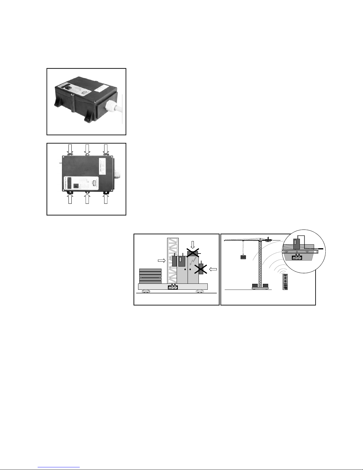
Mounting possibility of the receiver
Compact-V.
.
WRONG
Mounting on a tower slewing crane.
To p s le wi ng cr an e: M oun t t he a nte nn a w it h
extension cable horizontally.
RIGHT
The receiver is connected to the unit to be controlled with the multi-pin connecting
cable supplied. Please observe the instructions issued by the manufacturer of the unit
to be controlled!
The power supply of the receiver is generally effected by the connecting cable.
We recommend urgently to realize this connection via a central, well
accessible, multi-pin plug connector (for example HTS-plug connector series
HE/HB/HN/HA or comparable ones of other manufacturers) to make possible a quick
and clear fault diagnosis in the service case and to take off the receiver without an
expenditure of assembly.
In general, an earth lead is required in case the units to be controlled have not previously been operated by radio control. Failing this, the
receiver electronic circuit will not receive any power supply. Ensure that the operating voltage of the receivercomplieswiththeelectricalspecificationsof
the unit to be controlled. The applicable operating voltage is specified in the supplement.
Never expose the receiver to a high pressure cleaning jet. This applies to the
transmitter also.
The receiver should always be fixed vertically at the outside panel of the switching cabinet. (The antenna should always reach over the top of the panel.)
You hav e to make sure that the antenna is not shi elded b y me tal par ts tota lly or partly.
Mounting the receiver in a cabine or in a switching cabinet the antenna should be
layed with an extension cable to the outside and be attached with the fastening
strapping as horizontally as possible with distance to the shielding metal parts.
In general the antenna should always be mounted in such a way so that the antenna
is still visible with each change of position of the transmitter.
%
%
%
%
%
%
WRONG
RIGHT
Compact-V
Page 4
To m ai nt ai n o pe ra t io na l s af et y, a re gu la r f u nc ti on ch ec k o f t h e N BB r ad io r em ot e c on tr ol i s
necessary. In single-shift day-to-day operation, we recommend performing this check at
least once a week. Checking is possible using the display lights provided on the receiver.
To d o s o, t he t ra ns mi tt er m us t b e s e t t o t he r ea dy- to -op er at e s ta te .
First connect justthe receiver - the transmitter remains switchedoff.
Ensure in particular that there is nobody in the danger area.
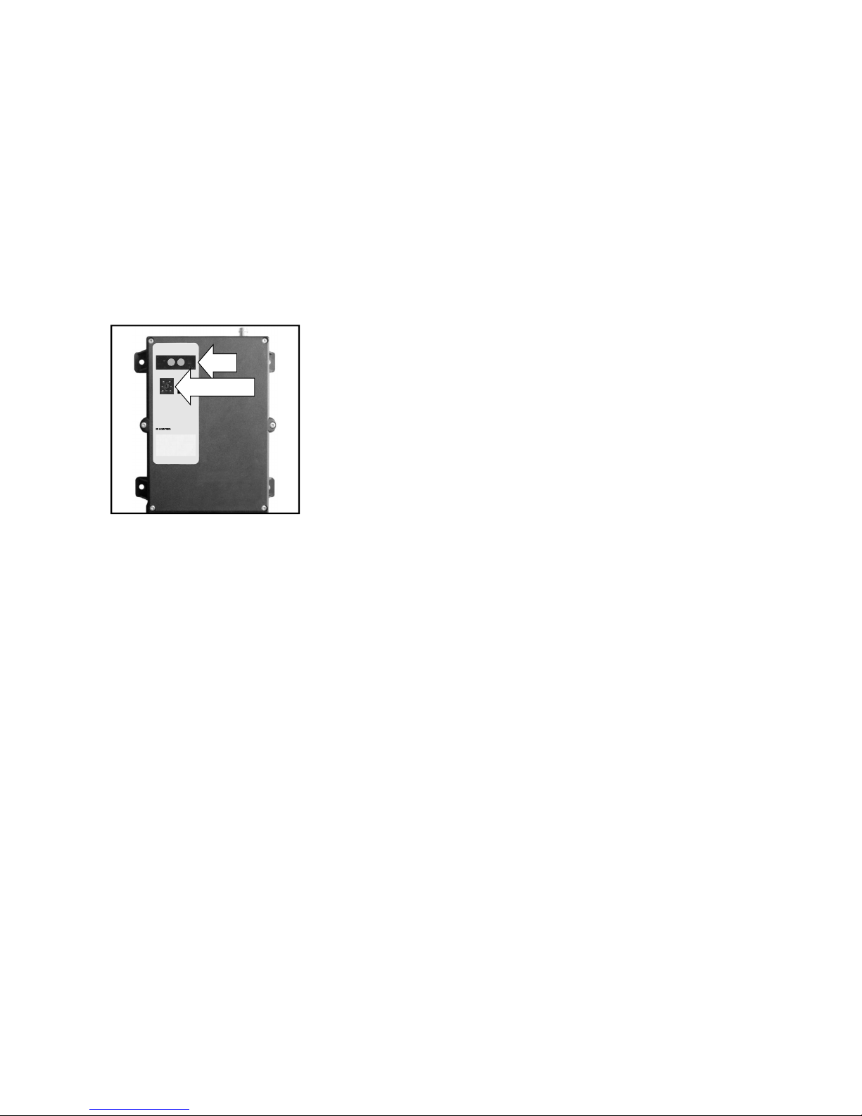
Irregular flashing means that the HF channel is probably at
fault - please set another channel.
If this LED flashes, the HF channel is at fault (not in the
scanner operation).
Steady light notifies the operator that an output function is
critical due to over current.
%
%
%
%
%
ACCIDENT RISK!
STOP, resp.
Activate the transmitter by unlocking the EMERGENCY STOP switch, resp.
pressing the key "START/ON/HORN".
Now check the commands (always start with the lowest stage) and check for
correct function of the unit to be controlled.
Press the EMERGENCY STOP switch at the
transmitter until the switch engages, resp. press the STOP key. Then observe if
the unit to be controlled is switched off (time to switch off according to
the application).
Service plug: For NBB service only.
EMERGENCY STOP check.
Checking the LED's at the receiver Compact-V:
LED 1 green: POWER ON. If LED fails to come on, check the power supply.
If the power lead is OK, call in the after-sales service.
LED 2 yellow: HF PRESENT. Steady light when transmitter is switched on
(insignificant for scanner operation).
LED 3 green: Flashes evenly during fault-free operation.
LED 4 red:
4. FUNCTION CHECK
1 2
www.nbb.de
®
COMPACT-V
X
3.820.1195
LEDS
SERVICE PLUG
Page 5

The identification plates statethe type of transmitter orreceiver, the factory number, the
frequencyrange and theapprovalnumber for nonEU countries.
Always statethe factorynumber in all yourqueries.
Your NBB radio remo te control is largel y maint enance-free. Never the less, please no tice
the followingpoints:
Remove any leftoverbuilding materials!
During electro-welding work on the unit tobe controlled,disconnect the receiver from
the currentsupply! Otherwisethere isa riskof damageto thereceiver's electronic sy-
stem!
Check wear andtear parts likedust shieldtops regular!
We grant a function warranty for 12 months after the sale date for all NBB radio remote
controls (transmitter, receiver, charger). The warranty covers working time and material
used. Shipping costs shall be charged to the customer. The warranty shall not cover:
wear and tear parts, relays and batteries. The function warranty shall be invalidated in the
case ofdamage, accident damage, negligence, incorrect use, non-compliance with operating conditions, non-compliance with operating, testing and maintenance instructions,
and repairs orunit modificationsnot authorised by NBB.
NBB shallnot be liablefor indirectdamage andreserves theright to decideon repair or replacement.
Do not attempt to continueworking witha defectiveNBB radioremote control. Eveninitially minor defects might bethe start of amore extensive defect.
Do not try to repair the NBBradio remote control yourself. Ifthere is any fault please contact your dealeror ourcompany.
%
%
%
Example:
X X
Tra nsm itt er Ty pe / Ver sio n:
Factory No.:
Frequency:
HyPro
999 899 4990
Mhz
X
Receiver Type / Version:
Factory No.:
Frequency:
Compact-V
999 899 4990
Mhz
8. IN CASE OF DEFECTS
7. WARRANTY
6. MAINTENANCE
5. IDENTIFICATION PLATES
Page 6
Page 6
USA:
IC CANADA:
NOTE: This equipment has been tested and found to comply with the limits for a Class A
digital device, pursuant to Part 15 of theFCC Rules.These limitsare designed to provide
reasonable protection against harmful interference when the equipment is operated in
acommercialenvironment.Thisequipmentgenerates,uses,andcanradiateradio
frequencyenergyand, ifnot installedand used in accordance withthe instruction manual,
may cause harmful interference to radio communications. Operation of this equipment
in a residential area is likely to cause harmful interference in which casetheuserwillbe
required to correct the interference at his own expense.
The installer of this radio equipment must ensure that the antenna is located
or pointed such that it does not emit RF field in excess of Health Canada limits for the
general population; consult Safety Code 6, obtainable from Health Canada’s website
www.hcsc.gc.ca/rpb
This devicecomplies with IndustryCanada license-exempt RSSstandard(s).
Operation is subject to the following twoconditions:
(1) this devicemay not causeinterference,and
(2) this device must acceptany interference,including interferencethat may cause unde-
sired operation ofthe device.
RSS-GEN 8.3 statement:
This radio transmitter (identify the device by certification number) has been approved by
Industry Canada to operate with theantenna types listedbelow with the maximumpermissible gain indicated. Antennatypes not included in this list, having a gain greater than the
maximumgain indicatedfor that type, arestrictly prohibited for usewith this device.
Please update accordingly
Cet appareil est conforme avecIndustrie Canadaexempt de licence Rss standard(s).
Son fonctionnement estsoumis auxdeux conditions suivantes:
(1) cet appareilne peutcauser d'interférences,et
(2) cet appareil doit acceptertoute interférence,y compris des interférences qui peuvent
provoquerun fonctionnementindésirable du périphérique.
ATTENTION:
Changes or modifications not expressly approved by the manufacturer could void the
user's authority to operate the equipment!
FCC part 15.203 statement:
This device is delivered and installed by the original manufacturer of the machine or
delivered and installed by NBB Controls Inc, Richmond VA. It is approved by FCC to
operate with the antenna originally supplied by the original manufacturer of the
machine or NBB Controls, Inc, Richmond VA. It is unlawful to change the antenna or
change the antenna installation. Only antennas declared as original spareparts are
allowed. Otherwise there is now allowance and it is illegal to operate this device !
Attention:
9. US-FCC and CANADA IC
Page 7

®
TECHNICAL DATA
Page 8

Bedienungsanleitung Compact-V,
Englisch, Teile-Nr. 3.150.1251, Stand 04.08
®
APPROVALS AND CERTIFICATES
Approvals EU countries:
EC Declaration of Conformity
M-Zert mbH
X X
Enclosure:
Obtainable at demand:
Certificate DIN EN ISO 9001:2008
©NBBControls+ComponentsGmbH
Otto-Hahn-Straße 3-5
DE-75248 Ölbronn-Dürrn
Tel.: 0 7 2 3 7 / 9 9 9 - 0
Fax: 0 72 37 / 9 99 - 1 99
eMail: [email protected]
http://www.nbb.de
We reserve the right to alter specifications without notice.
 Loading...