


2010-04-20 P/N: 240-0008-00-02
Copyright 2009-2010 NavWorx ® Page 1 of 46 All rights reserved. Printed in the U.S.A.
ADS600-B™
Installation and User Manual
®

2010-04-20 P/N: 240-0008-00-02
Copyright 2009-2010 NavWorx ® Page 2 of 46 All rights reserved. Printed in the U.S.A.
Business Address:
NavWorx Inc.
3906 Industrial St, Suite 100
Rowlett, TX 75088
Telephone:
(888)-NAVWORX (628-9679)
Facsimile:
888- 628-9679
Email: support@NavWorx.com
Website: www.NavWorx.com
Information in this document is subject to change without notice. NavWorx reserves the right to
modify its products and documentation without notice and is under no obligation to notify
anyone of such changes or improvements.
NavWorx is a registered trademark of NavWorx Incorporated. ADS600-B™ is a trademark of
NavWorx Incorporated. These trademarks may not be used without the express written
permission of NavWorx Incorporated.
No part of this document may be copied, reproduced, transmitted, disseminated, downloaded or
stored on any storage medium without the express written permission of NavWorx. NavWorx
grants permission to download a single copy of this document onto a hard drive or other
electronic storage medium to be viewed for personal use as long as the downloaded or printed
copy contains the complete text of this copyright notice. Unauthorized commercial distribution
of any revision of this documentation is strictly prohibited.

2010-04-20 P/N: 240-0008-00-02
Copyright 2009-2010 NavWorx ® Page 3 of 46 All rights reserved. Printed in the U.S.A.
Revision History
Revision
Date
Comments
01
04/20/2010
Initial release
02
05/11/2010
Revised FCC statement

2010-04-20 P/N: 240-0008-00-02
Copyright 2009-2010 NavWorx ® Page 4 of 46 All rights reserved. Printed in the U.S.A.
List of Effective Pages
Page Rev
Page Rev
Page Rev
Page Rev
Page Rev

2010-04-20 P/N: 240-0008-00-02
Copyright 2009-2010 NavWorx ® Page 5 of 46 All rights reserved. Printed in the U.S.A.
End User License Agreement (EULA)
Terms. By installing or using the ADS600-B (“product”), you agree to be bound by the terms and conditions of the
following license agreement. Please read this agreement carefully. NavWorx Incorporated ("NavWorx") grants you
a limited, non-exclusive license to use the product. Title, ownership rights, and intellectual property rights in and to
the product remain with NavWorx.
Refund. If you do not agree to the terms of this EULA, NavWorx Inc. is unwilling to license the product to you. In
such event, you may not use the licensed product, and you should promptly contact NavWorx for a refund. The
product must not have been used or installed in order to obtain a full refund.
No Warranties. Except as expressly provided in the limited warranty section, the products’ hardware and its
operating system software are provided to you “as is” without warranty of any kind, either expressed or implied,
including, but not limited to, waranties of noninfringement, merchantability, and /or fitness for a particular purpose.
The entire risk of the quality and performance of both the software and hardware is with the user.
Copyright. You acknowledge that the product is the property of NavWorx and is protected under United States of
America copyright laws and international copyright treaties. You further acknowledge that the structure,
organization, and source design of the hardware and software are valuable trade secrets of NavWorx. You agree not
to open the product, break the EULA seal, nor decompile, disassemble, modify, reverse assemble, reverse engineer,
or reduce to human readable form the hardware or software or any part thereof or create any derivative works based
on the product.
No Liability for Consequential Damages. NavWorx Inc. and its suppliers shall not be held liable for any damages
suffered or incurred by you (including, but not limited to, general, special, consequential or incidental damages for
loss of business profits, business interruption, personal compensation and the like), arising from or in connection
with the delivery, use, or performance of the product and its software.
Customer Remedies. NavWorx Inc. and its suppliers entire liability and your exclusive remedy shall be, at
NavWorx’ option, either (1) return of the product purchase price, not to exceed list price, or (2) repair or
replacement of the product which is returned to NavWorx with original proof of purchase.

2010-04-20 P/N: 240-0008-00-02
Copyright 2009-2010 NavWorx ® Page 6 of 46 All rights reserved. Printed in the U.S.A.
Disclaimer
Symbology seen throughout this documentation highlight important information. The following table defines how to
interpret these symbols:
Symbol
Description
Hazardous.
Warning.
Important.
The ADS600-B is used as an aid to visual acquisition of traffic and weather and it is to be used only for pilot
and crew situational awareness.
The ADS600-B does not relieve the flight crew of seeing and avoiding traffic, obstacles and weather.
Installation of the ADS600-B does not relieve the pilot of consulting approved data sources prior to and during each
flight.
The ADS600-B is not a collision-avoidance-device. Any deviation from ATC clearance, given cockpit
information derived from the ADS600-B, must be approved by ATC.
The ADS600-B is a Universal Access Transceiver (UAT) that interfaces with an MFD or CDTI to display
UAT, TIS-B and FIS-B products. NavWorx is not responsible for how a display device renders these products. Nor
is NavWorx is not responsible for the failure of the display device to render these products.
The ADS600-B receives TIS-B and FIS-B products from ADS-R ground stations. NavWorx is not
responsible for the content, or lack of content, in TIS-B and FIS-B product offerings by the FAA.
NavWorx is not responsible for the failure of ADS-R groundstations to broadcast TIS-B and FIS-B products.
NavWorx is not liable for damages as a result of use or misuse of the ADS600-B.
NavWorx has tested the product in accordance with FAA guidance material. However, issues may still be
present. We’ll make a best faith effort to resolve issues as they arise.
This product is licensed under an End User License Agreement (EULA). If you don’t agree with the EULA,
or this Disclaimer, you must return the equipment.

2010-04-20 P/N: 240-0008-00-02
Copyright 2009-2010 NavWorx ® Page 7 of 46 All rights reserved. Printed in the U.S.A.
NavWorx Two Year Limited Warranty
Limited Warranty for FAA Certified Products. Certified NavWorx products are warranted to be free from defects in material
and workmanship for two years from the date of original purchase. For the duration of the warranty period, at its option,
NavWorx will repair or replace any product which fails during normal use. No charge will be made to the customer for parts and
labor for product repair or replacement provided that the customer shall be responsible for all shipping cost. NavWorx, at its sole
discretion, retains the exclusive right to either repair or replace the product unit with a new unit or with a newly reconditioned
unit. Any replacement product will be warranted for the remainder of the original warranty period or ninety (90) days, whichever
is longest.
Limited Warranty for Non-Certified Products. Non-certified NavWorx products are warranted to be free from defects in
material and workmanship for two years from the date of first flight of the experimental aircraft in which the product is installed.
Customer must provide proof of first flight when requesting warranty service. For the duration of the warranty period, at its
option, NavWorx will repair or replace any product which fails during normal use. No charge will be made to the customer for
parts and labor for product repair or replacement provided that the customer shall be responsible for all shipping cost. NavWorx,
at its sole discretion, retains the exclusive right to either repair or replace the product unit with a new unit or with a newly
reconditioned unit. Any replacement product will be warranted for the remainder of the original warranty period or ninety (90)
days, whichever is longest.
Restrictions. This Limited Warranty does not apply if (a) the product has not been installed, operated, or maintained in
accordance with instructions supplied by NavWorx, (c) has been altered, except by NavWorx or its authorized representative, or
(c) has been subjected to abnormal physical or electrical stress, abnormal environmental conditions, misuse, negligence, or
accident, (d) the factory applied original case seals or serial number label has been broken, altered or removed from the product.
Disclaimer of Warranty. EXCEPT AS SPECIFIED IN THIS WARRANTY SECTION, ALL EXPRESS OR IMPLIED
CONDITIONS, REPRESENTATIONS, AND WARRANTIES INCLUDING, WITHOUT LIMITATION, ANY IMPLIED WARRANTY
OR CONDITION OF MERCHANTABILITY, FITNESS FOR A PARTICULAR PURPOSE, STATUTORY OR OTHERWISE ARE
HEREBY EXCLUDED TO THE EXTENT AN IMPLIED WARRANTY CANNOT BE EXCLUDED. SUCH WARRANTY IS
LIMITED IN DURATION TO THE EXPRESS WARRANTY PERIOD. BECAUSE SOME STATES OR JURISDICTIONS DO NOT
ALLOW LIMITATIONS ON HOW LONG AN IMPLIED WARRANTY LASTS, THE ABOVE LIMITATION MAY NOT APPLY.
THIS WARRANTY GIVES THE CUSTOMER SPECIAL LEGAL RIGHTS AND THE CUSTOMER MAY HAVE OTHER LEGAL
RIGHTS THAT MAY VARY FROM JURISDICTION TO JURISDICTION.
NAVWORX SHALL NOT BE LIABLE, IN ANY EVENT, FOR ANY INCIDENTAL, SPECIAL, INDIRECT OR
CONSEQUENTIAL DAMAGES, WHETHER RESULTING FROM THE USE, MISUSE OR INABILITY TO USE THE PRODUCT
OR FROM DEFECTS IN THE PRODUCT. BECAUSE SOME STATES OR JURISDICTIONS DO NOT ALLOW THE EXCLUSION
OF INCIDENTAL OR CONSEQUENTIAL DAMAGES THE ABOVE LIMITATIONS MAY NOT APPLY TO YOU.
Warranty Service. Warranty repair service shall be provided directly by NavWorx. To obtain warranty service, an original
copy of the sales receipt for the product from NavWorx or a retailer is required. The following steps describe how to return your
unit for warranty service.
Step 1. Call or email NavWorx and describe the problem that you are having and request a Return Material
Authorization (RMA) tracking number. Also, provide the unit’s serial number, your shipping address and daytime
telephone number.
Telephone
(888)-NAVWORX (628-9679)
Email
support@NavWorx.com
Step 2. Once you have received an RMA number, securely pack the unit and ship it, insured, to the following address:
NavWorx Incorporated
RMA Number: (insert your RMA number here)
3906 Industrial St, Suite 100
Rowlett, TX 75088

2010-04-20 P/N: 240-0008-00-02
Copyright 2009-2010 NavWorx ® Page 8 of 46 All rights reserved. Printed in the U.S.A.

2010-04-20 P/N: 240-0008-00-02
Copyright 2009-2010 NavWorx ® Page 9 of 46 All rights reserved. Printed in the U.S.A.
Table of Contents
Revision History ...................................................................................................................... 3
List of Effective Pages .............................................................................................................. 4
End User License Agreement (EULA) ...................................................................................... 5
Disclaimer................................................................................................................................ 6
NavWorx Two Year Limited Warranty ..................................................................................... 7
Definitions and Acronyms ...................................................................................................... 12
1 Accessories and Packing List............................................................................................ 13
1.1 Unpacking Equipment................................................................................................ 13
1.2 Package Contents................................................................................................ ....... 13
2 About this Manual............................................................................................................ 14
2.1 FCC Grant of Equipment Authorization ..................................................................... 14
3 Equipment Description ..................................................................................................... 14
3.1 Overall Specifications ................................................................................................ 16
3.2 Transmitter Specification ................................................................ ........................... 17
System Interfaces .......................................................................................................... 18
3.3 ................................................................................................ ...................................... 18
3.3.1 Display................................................................................................................ 19
3.3.2 Maintenance Port................................................................................................. 19
3.3.3 Annunciator Output ............................................................................................. 19
3.4 Antenna Requirements ................................................................ ............................... 19
3.4.1 GPS Antenna ....................................................................................................... 19
3.4.2 UAT Antenna ...................................................................................................... 19
3.5 Installation................................................................................................................. 20
3.5.1 Materials Not Supplied ................................ ........................................................ 20
3.5.2 Tools Required .................................................................................................... 21
3.5.3 Equipment Mounting ........................................................................................... 21
3.5.4 Cabling and Wiring ............................................................................................. 22
3.5.5 Air Circulation and Cooling ................................ ................................................. 22
3.6 Electrical Connections ............................................................................................... 22
3.6.1 Connectors .......................................................................................................... 22
3.6.2 Interface Connector Definition ................................................................ ............. 23
3.6.3 I/O Connector (P1) .............................................................................................. 24
3.7 Functional Descriptions ............................................................................................. 26
3.7.1 Power .................................................................................................................. 26

2010-04-20 P/N: 240-0008-00-02
Copyright 2009-2010 NavWorx ® Page 10 of 46 All rights reserved. Printed in the U.S.A.
3.7.2 Discrete Outputs .................................................................................................. 26
3.7.3 Discrete Inputs .................................................................................................... 26
3.7.4 PPS Time Mark Input ................................ .......................................................... 27
3.7.5 Serial Interfaces ................................................................................................... 27
3.8 Post Installation Check............................................................................................... 28
3.8.1 Maintenance PC ................................................................................................ .. 28
3.8.2 Electrical Load Analysis ...................................................................................... 32
3.8.3 Mounting Check .................................................................................................. 32
3.8.4 Wiring Check ................................................................................................ ...... 32
3.8.5 Functional Test .................................................................................................... 32
3.8.6 Weight and Balance ............................................................................................. 32
4 Limitations ...................................................................................................................... 33
4.1 Traffic Display .......................................................................................................... 33
5 Troubleshooting ............................................................................................................... 33
6 Maintenance .................................................................................................................... 33
6.1 Altitude Source .......................................................................................................... 33
6.2 Calibration................................................................................................................. 33
6.3 Tune-Up ................................................................................................ .................... 33
6.4 Battery Replacement ................................................................ .................................. 33
6.5 Cleaning .................................................................................................................... 33
Traffic and Weather Displays ................................................................................................. 34
Product Registration ............................................................................................................... 35
Wiring Diagrams ................................................................ .................................................... 36

2010-04-20 P/N: 240-0008-00-02
Copyright 2009-2010 NavWorx ® Page 11 of 46 All rights reserved. Printed in the U.S.A.
List of Tables
Table 1-1: Package Contents ......................................................................................................................................... 13
Table 1-2: ADS600-B Installation Kit Contents (P/N 210-0004-00-00) ...................................................................... 13
Table 3-1: Acceptable ADS600-B UAT Antennas ....................................................................................................... 20
Table 3-2: Acceptable ADS600-B GPS Antennas ........................................................................................................ 20
Table 3-3: Crimp Tools for High Density 22-24 AWG Socket Contact....................................................................... 21
Table 3-4: Connectors.................................................................................................................................................... 23
Table 3-5: I/O Connector Pin-Out (P1) ......................................................................................................................... 25
Table 3-6: ADS600-B Maintenance Commands........................................................................................................... 30
Table 3-7: Recommended Circuit Breaker .................................................................................................................... 32
Table 3-8: ADS600-B Weights ..................................................................................................................................... 32
List of Figures
Figure 3-1: Top view of ADS600-B UAT Data Link Transceiver 15
Figure 3-2: ADS600-B UAT Data Link Transceiver System Diagram 18
Figure 3-3: ADS600-B Mounting Bracket Pattern 22
Figure 3-4: ADS600-B DB37, UAT and GPS Connectors 23
Figure 3-5: 37 Pin D-Sub Male Connector (P1) 24

2010-04-20 P/N: 240-0008-00-02
Copyright 2009-2010 NavWorx ® Page 12 of 46 All rights reserved. Printed in the U.S.A.
Definitions and Acronyms
ADC Air Data Computer
ADS600-B Automatic Dependent Surveillance universal access transceiver
ADS-B Automatic Dependent Surveillance Broadcast
ADS-R Automatic Dependent Surveillance Rebroadcast
AHRS Attitude Heading Reference System
ATC Air Traffic Control
CDTI Cockpit Display of Traffic Information
FAA Federal Aviation Administration
FIS-B Flight Information Services Broadcast
MFD Multifunction Display
GBT Ground Based Transceiver (also known as ADS-R)
PC Personal Computer
SDA System Design Assurance
SIL System Integrity Level
STC Supplemental Type Certificate
TIS-B Traffic Information Services Broadcast
TSO Technical Standard Order
UAT Universal Access Transceiver
WAAS Wide Area Augmentation System

2010-04-20 P/N: 240-0008-00-02
Copyright 2009-2010 NavWorx ® Page 13 of 46 All rights reserved. Printed in the U.S.A.
1 Accessories and Packing List
1.1 Unpacking Equipment
Carefully unpack the equipment from the shipping container. Inspect the ADS600-B unit and
the package contents for evidence of shipping damage. Retain the shipping container and
packaging material for reshipment if necessary.
1.2 Package Contents
The items included in the ADS600-B package are listed in Tables 1-1and 1-2.
Table 1-1: Package Contents
Part #
Quantity
Description
210-0004-00-00
1
ADS600 Installation Kit (see Table 1-2 for details)
200-0012-XX-XX
1
ADS600-B UAT Data Link Transceiver
240-0008-00-01
1
ADS600-B UAT Installation and User Manual
Table 1-2: ADS600-B Installation Kit Contents (P/N 210-0004-00-00)
Part #
Quantity
Description
201-205167-1
1
Receptacle Female, DSUB 37-pin
201-205161-1
1
Receptacle Female, DSUB 9-pin
201- DC-24660-33
1
DSUB 37-pin back-shell
201-5745407-1
1
Connector DSUB Latch Slide 37 position
201-16384
8
Cable tie
201-M39029/63-368
20
Crimp contact, DSUB, 20 to 24 AWG wire

2010-04-20 P/N: 240-0008-00-02
Copyright 2009-2010 NavWorx ® Page 14 of 46 All rights reserved. Printed in the U.S.A.
2 About this Manual
This manual describes the installation and checkout procedures for the ADS600-B UAT Data
Link Transceiver.
The ADS600-B unit is intended to be installed in aircraft that do not require an STC for
installation.
2.1 FCC Grant of Equipment Authorization
This equipment has been issued an FCC Grant of Equipment Authorization. The FCC ID is marked on the
equipment nameplate.
3 Equipment Description
The ADS600-B UAT Data Link Transceiver contains a GPS/WAAS receiver and a Universal
Access receiver and transmitter. This unit transmits a GPS position and aircraft information
message once per second. Additionally, this unit receives messages from other UAT equipped
aircraft and receives TIS-B/FIS-B messages from GBTs. Data received by the ADS600-B is
output to a display device.

2010-04-20 P/N: 240-0008-00-02
Copyright 2009-2010 NavWorx ® Page 15 of 46 All rights reserved. Printed in the U.S.A.
Figure 3-1: Top view of ADS600-B UAT Data Link Transceiver

2010-04-20 P/N: 240-0008-00-02
Copyright 2009-2010 NavWorx ® Page 16 of 46 All rights reserved. Printed in the U.S.A.
3.1 Overall Specifications
This section includes the physical, electrical, performance and environmental specifications for
the ADS600-B UAT Data Link Transceiver.
Physical
Height: 2.1 inches
Width: 5.4 inches (w/o mounting bracket)
7.3 inches (w/ mounting bracket)
Depth: 6.2 inches
Weight: 1.5 lbs (w/o mounting bracket, excluding cables)
1.6 lbs (w/ mounting bracket, excluding cables)
Electrical
Voltage: 9-36VDC
Input Current (10W nominal): 0.7A @ 14VDC, 0.41A @ 24VDC
UAT Performance
Regulatory: DO-282B
Frequency: 978MHz
Tolerance: +/- 20ppm
Data Rate: 1.04167 Mbps
Receiver Sensitivity: Exceeds 90%MSR@-95dBm
Transmit Power: 40W nominal at antenna
Equipment Class: A1S (single bottom UAT antenna)
GPS/WAAS Receiver Performance
Number of channels: 20
Frequency: 1575.42MHz L1
Sensitivity (Tracking Mode): -159dBm (Tracking mode)
Sensitivity (Acquisition Mode): -142dBm (Acquisition mode)
TTFF Hot (valid almanac, position, time and ephemeris): 1 second
TTFF Warm (valid almanac, position and time): < 35 seconds
TTFF Cold (valid almanac): < 35 seconds
Reacquisition (<10seconds obstruction): 0.1seconds
Position Update Interval: 5Hz
Velocity: 1,000 Kts maximum @ 60,000 ft MSL
Datum: WGS-84
Environmental
Operating temperature: -20°C to +55°C
Storage temperature: -55°C to +85°C
Temperature variation: 5°C per minute

2010-04-20 P/N: 240-0008-00-02
Copyright 2009-2010 NavWorx ® Page 17 of 46 All rights reserved. Printed in the U.S.A.
Humidity: 94% at 65°C
Maximum continuous altitude: 40,000 feet
Decompression: 40,000 feet
External Cooling: Not required
Avionics Interfaces
Annunciator Outputs: Capable of sinking 500mA for turning on annunciator lamp
Altitude Encoder: RS232 asynchronous serial, ARINC429 ADC/AHRS source
Maintenance Port: RS232 asynchronous serial
External Position Input: From ARINC743A source
Display: RS232 asynchronous serial (Pass-through or Traffic interfaces)
RS422 asynchronous serial (Pass-through or Traffic interfaces)
ARINC735 Traffic interface
TIS-A Traffic interface
3.2 Transmitter Specification
The ADS600-B is a non-TSO device that complies with RTCA DO-282B. DO-282B compliant
messages transmitted by the ADS600-B unit assign the System Integrity Level (SIL) to unknown
(0) and the System Design Assurance (SDA) level to unknown (0).
2010-04-20 P/N: 240-0008-00-02
Copyright 2009-2010 NavWorx ® Page 18 of 46 All rights reserved. Printed in the U.S.A.
3.3 System Interfaces
Figure 3-2: ADS600-B UAT Data Link Transceiver System Diagram
GPS Antenna
Maintenance Port
UAT Antenna
Display (MFD, Portable, etc.)
A/C Power
ADS600-B
Annunciator (Lamp)
Altitude
Encoder
DB37 Connector

2010-04-20 P/N: 240-0008-00-02
Copyright 2009-2010 NavWorx ® Page 19 of 46 All rights reserved. Printed in the U.S.A.
3.3.1 Display
The ADS600-B outputs to compatible displays both traffic and weather information. The ability
to display traffic and/or weather depends on the display device.
3.3.2 Maintenance Port
The ADS600-B provides an RS232 communication port that is used to configure and monitor the
status of the ADS600-B system via a computer. The maintenance port is required to be
connected.
3.3.3 Annunciator Output
The ADS600-B can drive an external annunciator lamp.
3.4 Antenna Requirements
3.4.1 GPS Antenna
The ADS600-B requires one GPS antenna. GPS antenna performance is critical to the operation
of the ADS600-B GPS/WAAS receiver. Table 3-2 contains a list of GPS antennas that are
recommended for use with the ADS600-B. Other GPS antennas may meet the installation
requirements of the ADS600-B. Contact the factory to ensure antenna compatibility prior to
installing your ADS600-B.
3.4.2 UAT Antenna
The ADS600-B requires one UAT antenna meeting the following specification: standard 50Ω
vertically polarized antenna with a VSWR < 1.7:1 at 978MHz. Table 3-1 contains a list of UAT
antennas that are recommended for use with the ADS600-B.
Some types (1030 and 1090MHz) of transponder antennas use very thin radiator elements.
These types of antennas should be closely evaluated to determine their suitability as UAT data
link antennas.
Operating the ADS600-B without RF terminations on the UAT Antenna port can result in
equipment damage. Operate the ADS600-B with the UAT antenna port terminated with a
VSWR ratio of 3.0:1 or less.

2010-04-20 P/N: 240-0008-00-02
Copyright 2009-2010 NavWorx ® Page 20 of 46 All rights reserved. Printed in the U.S.A.
3.5 Installation
This section describes the installation of the ADS600-B including mounting, wiring and
connections.
Read this entire section before proceeding with the installation of the ADS600-B.
Follow avionics installation practices per FAA Advisory Circular (AC) 43.13-1B, 43-13-2A, or
FAA approved revisions to these documents.
Perform an electrical load analysis in accordance with AC 43.13-1B, Chapter 11, on the aircraft
prior to installation to ensure that the aircraft’s electrical system is capable of carrying the
ADS600-B load. Section 3.1 describes the power consumption of the ADS600-B.
3.5.1 Materials Not Supplied
The following items are required for the ADS600-B installation, but are not supplied:
UAT Antenna (Table 3-1 provides a list of recommended UAT Antennas)
GPS Antenna, if installing an external GPS input for ADS600-B (Table 3-2 provides a
list of recommended GPS Antennas)
Wire (MIL-W-22759/16 or equivalent)
Shielded wire (MIL-C-27500 or equivalent)
Circuit Breakers
Ring Terminals (for grounding)
Table 3-1: Acceptable ADS600-B UAT Antennas
Manufacturer
Part Num
Connector
Hole Template
RAMI
AV-74
BNC
http://www.rami.com/files/2/AV-74-Footprint.pdf
RAMI
AV-741
BNC
http://www.rami.com/files/2/AV-741-Footprint.pdf
Comant
CI-105
BNC
Comant
CI-105-11
TNC
Table 3-2: Acceptable ADS600-B GPS Antennas
Manufacturer
Part Num
Connector
Hole Template
RAMI
AV-GPS
BNC
http://www.rami.com/files/2/AV-GPS-Footprint.pdf
Comant
CI-2480-400
GPS Uses TNC
Comant
CI-420-200
TNC
Comant
CI-429-200
TNC

2010-04-20 P/N: 240-0008-00-02
Copyright 2009-2010 NavWorx ® Page 21 of 46 All rights reserved. Printed in the U.S.A.
3.5.2 Tools Required
The D-Sub connector supplied with the ADS600-B uses crimp contacts. Table 3-3 identifies the
crimp tool required to ensure consistent and reliable crimp contact connections for the D-Sub
connector.
Table 3-3: Crimp Tools for High Density 22-24 AWG Socket Contact
Type
Hand Crimping Tool
Positioner
Insertion/Extraction Tool
Military P/N
M22520/2-01
M22520/2-09
M81969/1-04
Positronic
9507
9502-3
M81969/1-04
AMP
601966-1
601966-6
91067-1
Daniels
AFM8
K42
M81969/1-04
Astro
615717
615725
M81969/1-04
3.5.3 Equipment Mounting
The ADS600-B may be mounted in either a portable or remote mount configuration.
3.5.3.1 ADS600-B Portable Mount
The ADS600-B may be mounted in a portable configuration. The unit may be placed on a glare
shield or any hard surface and affixed in place using Velcro®. The unit may also be portably
attached to the aircraft using a RAM® mounting system.
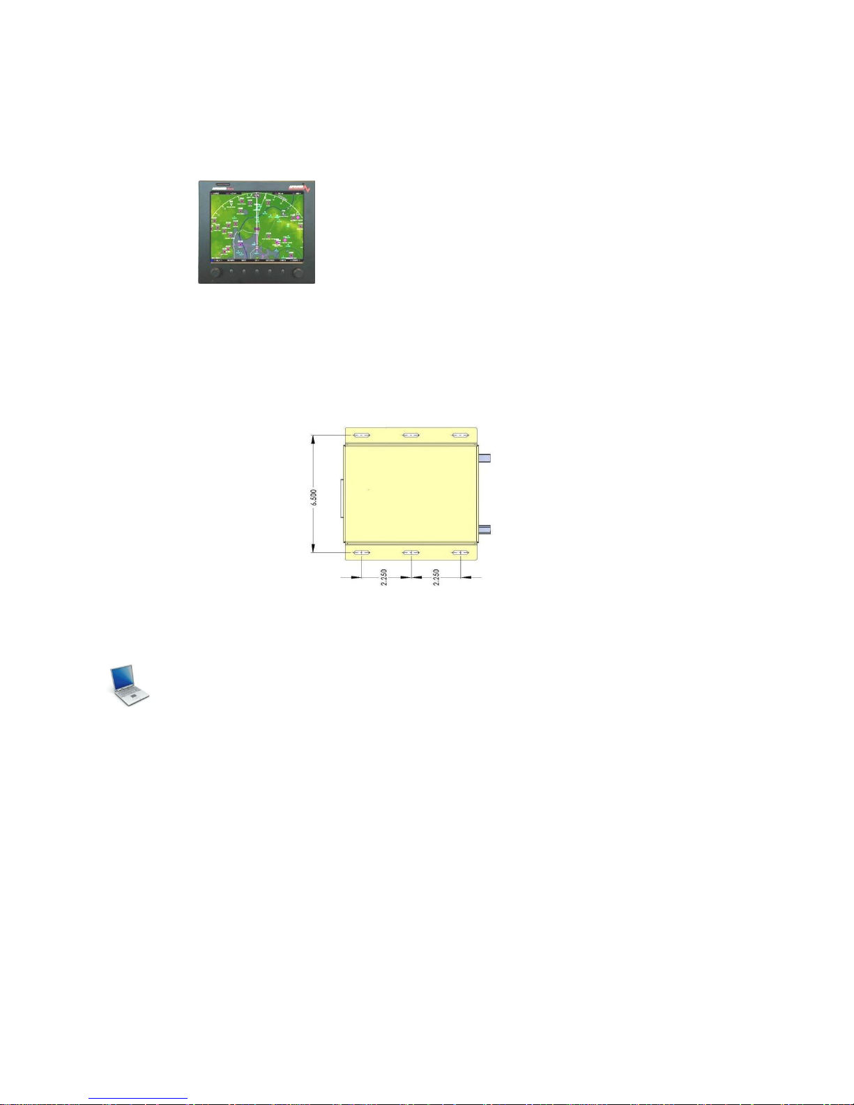
3.5.3.2 ADS600-B Remote Mount
This option is recommended for non-certified, experimental or light sport aircraft to remotely
mount the ADS600-B to the aircraft. The ADS600-B may be ordered with optional mounting
brackets. Figure 3-3 describes the ADS600-B mounting bracket bolt pattern.

2010-04-20 P/N: 240-0008-00-02
Copyright 2009-2010 NavWorx ® Page 22 of 46 All rights reserved. Printed in the U.S.A.
Figure 3-3: ADS600-B Mounting Bracket Pattern
3.5.3.3 Antenna Placement
3.5.3.3.1 GPS Antenna
3.5.3.3.2 UAT Antenna
The UAT Antenna MUST be installed no less than 5 feet from any Transponder
/TCAS/TAS or DME antenna. Failure to adhere to this critical installation note will result in
failure of the ADS600-B and void your warranty.
3.5.4 Cabling and Wiring
3.5.5 Air Circulation and Cooling
3.6 Electrical Connections
3.6.1 Connectors
Table 3-4 describes the connectors supplied with the ADS600-B installation kit. The kit also
contains crimp contacts for the D-Sub connector. Table 3-3 identifies the crimp tool required to
ensure consistent and reliable crimp contact connections.

2010-04-20 P/N: 240-0008-00-02
Copyright 2009-2010 NavWorx ® Page 23 of 46 All rights reserved. Printed in the U.S.A.
Table 3-4: Connectors
Ref
Description
Connector Type
Crimp Contact
P1
I/O
37 Pin D-Sub Receptacle
20-24 AWG socket contact
P2
UAT Antenna
TNC connector.
N/A
P3
GPS Antenna
TNC connector.
N/A
3.6.2 Interface Connector Definition
The following figure shows the side view of the ADS600-B depicting the DSUB and TNC
connectors.
Figure 3-4: ADS600-B DB37, UAT and GPS Connectors
P3 GPS Antenna
P2 UAT
P1 DB37 Connector

2010-04-20 P/N: 240-0008-00-02
Copyright 2009-2010 NavWorx ® Page 24 of 46 All rights reserved. Printed in the U.S.A.
3.6.3 I/O Connector (P1)
A 37 pin D-Sub connector interfaces to external equipment and aircraft power. This connector
can be found at the rear of the ADS600-B unit.
View looking at ADS600-B.
Figure 3-5: 37 Pin D-Sub Male Connector (P1)
The pin-out description for the I/O connector is defined in Table 3-5.

2010-04-20 P/N: 240-0008-00-02
Copyright 2009-2010 NavWorx ® Page 25 of 46 All rights reserved. Printed in the U.S.A.
Table 3-5: I/O Connector Pin-Out (P1)
Pin #
I/O
Name
Description
1
--
RESERVED
RESERVED
2 I Time mark In -
ARINC 743A Time Mark In -
3
--
Ground
RS232 Maintenance Port Ground
4 I RS232 Maintenance RX
RS232 Maintenance Port Serial Data Input
5 O RS232 TX
RS232 Display Serial Data Output
6
--
Ground
RS232 Altitude Encoder and TIS Output Ground
7 I Altitude Encoder RX
RS232 Altitude Encoder Input
8 O 429 OUT 1B
ARINC 429 Output Channel 1B
9 I 429 IN 1A
ARINC 429 Input Channel 1A
10
--
RESERVED
RESERVED
11 I External PPS TTL In
External PPS TTL In
12 O RS422 TX -
RS422 Display Channel Data Output -
13 I RS422 RX +
RS422 Display Channel Data Input +
14 O UAT Fail Out
UAT Fail Output (active low)
15 I TCAS RA Active In
TCAS Resolution Advisory Active Discrete In (active low)
16
--
RESERVED
RESERVED
17
--
RESERVED
RESERVED
18
--
Power +
Main Aircraft Power Input (+9 to +36VDC)
19
--
Power +
Main Aircraft Power Input (+9 to +36VDC)
20
--
RESERVED
RESERVED
21 I Time mark In +
ARINC 743A Time Mark In +
22 O RS232 Maintenance TX
RS232 Maintenance Port Serial Data Output
23
--
Ground
RS232 Display Ground
24 I RS232 RX
RS232 Display Serial Data Input
25 O TIS TX
TIS Serial Data Output
26
--
RESERVED
RESERVED
27 O 429 OUT 1A
ARINC 429 Output Channel 1A
28 I 429 IN 1B
ARINC 429 Input Channel 1B
29
--
RESERVED
RESERVED
30 O RS422 TX +
RS422 display channel data output +
31 I RS422 RX -
RS422 display channel data input -
32
--
RESERVED
RESERVED
33 I TCAS Operational In
TCAS Operational Discrete Input (active low)
34 I Air/Ground In
Air / Ground Discrete Input (active low)
35 O Suppression Output
Suppression Output (active high)
36 I Power Ground
Main Aircraft Power Ground
37 I Power Ground
Main Aircraft Power Ground

2010-04-20 P/N: 240-0008-00-02
Copyright 2009-2010 NavWorx ® Page 26 of 46 All rights reserved. Printed in the U.S.A.
3.7 Functional Descriptions
3.7.1 Power
Aircraft power is provided to the ADS600-B on the P1 I/O connector. The ADS600-B accepts
input power from +9 to +36 VDC.
P1-18 Power +
P1-19 Power +
P1-36 Power Ground
P1-37 Power Ground
3.7.2 Discrete Outputs
The ADS600-B provides discrete outputs to provide status and drive annunciator lamps or other
equipment. All discrete outputs are active low (i.e. grounded when active) and are of open
collector design, capable of sinking up to 500 mA.
3.7.2.1 UAT Fail Indicator
The UAT Fail Out (P1-14) is used to indicate the status of the ADS600-B receiver. UAT Fail
Out will be grounded when the ADS600-B has detected a system failure. Otherwise, this output
will be open.
3.7.2.2 Suppression Output
The Suppression Output (P1-35) is reserved for future use and is intended to suppress other Lband equipment (such as a transponder) when the UAT transmits. It will provide a high signal
(Vin – 1.5V) whenever the UAT is transmitting and ground otherwise.
3.7.3 Discrete Inputs
The ADS600-B accepts discrete inputs to provide additional status information from the aircraft
systems or equipment. All inputs are active low (i.e. grounded when active) and each input
presents a load of greater than 100 kΩ.
3.7.3.1 Air/Ground Discrete Input
The Air/Ground In (P1-34) is reserved for future use. It provides air/ground status input to the
ADS600-B. The function of this input is configurable via the Maintenance PC (refer to section
3.7). The Air/Ground Input must be configured for one of the following options:
A grounded Air/Ground In indicates that the aircraft is on the ground. Otherwise, an open
indicates that the aircraft is in the air.
An open Air/Ground In indicates that the aircraft is in the air. Otherwise, a grounded
Air/Ground In indicates that the aircraft is on the ground.

2010-04-20 P/N: 240-0008-00-02
Copyright 2009-2010 NavWorx ® Page 27 of 46 All rights reserved. Printed in the U.S.A.
An air/ground switch is not installed. The air/ground state is set automatically based on
the GPS ground speed. The air/ground speed threshold is configurable.
3.7.4 PPS Time Mark Input
When used with an external ARINC 743A position source, the time mark signals from the
navigation sensor are connected to the ADS600-B time mark input pins (P1-2 and P1-21).
3.7.5 Serial Interfaces
The ADS600-B provides two bi-directional RS-232 serial interfaces, one receive only RS232
interface, one transmit only RS232 interface, one bi-directional RS-422 interface and one
ARINC 429 input/output. These serial interfaces can be connected to:
Display(s)
Maintenance PC
Altitude Encoder
The serial port pin-outs are:
P1-13 RS422 Display Serial Data Input +
P1-31 RS422 Display Serial Data Input P1-12 RS422 Display Serial Data Output P1-30 RS422 Display Serial Data Output +
P1-9 ARINC 429 Input Channel 1A
P1-27 ARINC 429 Output Channel 1A
P1-28 ARINC 429 Input Channel 1B
P1-8 ARINC 429 Output Channel 1B
P1-7 RS232 Altitude Encoder Serial Data Input
P1-25 RS232 TIS Serial Data Output
P1-6 RS232 Altitude Encoder and TIS Output Ground
P1-24 RS232 Display Serial Data Input
P1-5 RS232 Display Serial Data Output
P1-23 RS232 Display Ground
P1-4 RS232 Maintenance Port Serial Data Input
P1-22 RS232 Maintenance Port Serial Data Output
P1-3 RS232 Maintenance PC Ground

2010-04-20 P/N: 240-0008-00-02
Copyright 2009-2010 NavWorx ® Page 28 of 46 All rights reserved. Printed in the U.S.A.
3.7.5.1 RS232 Altitude Encoder Input
An altitude encoder input may be provided through a RS232 serial data input (P1-7 and P1-6) to
the ADS600-B. The maintenance PC commands (see section 3.7) describe how to enable the
serial port for the Altitude Encoder Input. The baud rate for this port is also configurable via a
maintenance command.
3.7.5.2 RS232 TIS Output (Garmin portables GPSMAP® x96)
The ADS600-B may be configured to output TIS data via a RS232 serial data output (P1-6 and
P1-25) to a portable GPSMAP® display device. The maintenance PC commands (see section
3.7) describe how to enable the serial data port for the TIS Output. The baud rate for this port is
also configurable via a maintenance command.
3.7.5.3 RS422 In/Out Display
The ADS600-B may be configured to output to a display device using the RS422 serial interface
(P1-12, P-13, P1-30, and P1-31). The type of display device is configurable. The maintenance
PC commands (see section 3.7) allow the installer to select a display device, as well as, a baud
rate for the RS422 serial interface.
3.7.5.4 RS232 In/Out Display
The ADS600-B may be configured to output to a display device using the RS232 serial interface
(P1-5, P1-23, and P1-24). The type of display device is configurable. The maintenance PC
commands (see section 3.7) allow the installer to select a display device, as well as, a baud rate
for the RS232 serial interface.
3.7.5.5 RS232 Maintenance PC
The ADS600-B communicates with the maintenance PC using a RS232 serial interface (P1-3,
P1-4, and P1-22). This interface is used to view system status and to set the configuration of the
ADS600-B. The maintenance PC serial channel is fixed at 38,400 baud, 8 data, no parity, 1 stop.
3.7.5.6 ARINC429
The ADS600-B provides one ARINC 429 input and output (P1-8, P1-9, P1-27, and P1-28)
interface.
3.8 Post Installation Check
3.8.1 Maintenance PC
3.8.1.1 Using Maintenance Port with a Windows Terminal Emulator
For configuration and testing of the ADS600-B, a PC running a terminal emulator is required to
connect to the maintenance port of the ADS600-B.
With the ADS600-B powered on and the maintenance port connected to the PC terminal
emulator software, a test to determine if the emulator program is connected and working is to

2010-04-20 P/N: 240-0008-00-02
Copyright 2009-2010 NavWorx ® Page 29 of 46 All rights reserved. Printed in the U.S.A.
press any key – should you see the key appear on the emulator program then the ADS600-B is
echoing the character.
Type “Help” to view the list of all ADS600-B commands. See Table 3-6 for the complete list of
ADS600-B maintenance commands.

2010-04-20 P/N: 240-0008-00-02
Copyright 2009-2010 NavWorx ® Page 30 of 46 All rights reserved. Printed in the U.S.A.
3.8.1.2 Maintenance Commands
Table 3-6: ADS600-B Maintenance Commands
READ Commands
Command
Option
Description
HELP List maintenance commands.
READ
ALL
Display all pertinent status and configuration for unit.
READ
PORTS
Display mapping of protocol to RS232/RS422 ports.
READ
GPS ALL
Display GPS configuration and status.
READ
GPS SV
Display GPS service vehicle status.
READ
GPS <seconds>
Display GPS statistics at an interval as specified by seconds.
READ
ICAO
Display aircraft 24-bit ICAO address.
READ
OWNSHIP
Display ownship message.
READ
RS232
Display configuration of RS232 interface.
READ
RS422
Display configuration of RS422 interface.
READ
TM <seconds>
Display traffic manager information at an interval as specified by
<seconds>.
READ
UM <seconds>
Display uplink manager (FIS-B) information at an interval as specified
by <seconds>.
DISPLAY Commands
Command
Option
Description
DISABLE
COMPTIS
Disable Composite-TIS mode.
ENABLE
COMPTIS
Enable Composite-TIS mode.
MAP
<SKY|PASS|TA|A429S> <RS232|RS422>
Map protocols to physical port.
SET
BAUD ARINC429 <LOW|HIGH>
Set ARINC429 clock speed.
SET
BAUD RS232 <9600|19200|38400|57600|115200>
Set baud rate for RS232 display port.
SET
BAUD RS422 <9600|19200|38400|57600|115200>
Set baud rate for RS422 display port.
SET
MAXDIST [x.y]
Set maximum distance in 1/10
ths
of a nautical mile for traffic targets.
Traffic targets that are greater than this distance from the ownship
location will not be passed on to the display(s).
SET
MAXALT [feet]
Set maximum vertical distance in feet for traffic targets. Traffic targets
that are greater than this distance from the ownship location will not
be passed on to the display(s).
SET
PROTOCOL <PASS|TA|A429|SKY|NONE> |
<TISA|A429|A429S>
Enter 1 or 2 protocols.

2010-04-20 P/N: 240-0008-00-02
Copyright 2009-2010 NavWorx ® Page 31 of 46 All rights reserved. Printed in the U.S.A.
TRANSMITTER Commands
Command
Option
Description
ENABLE
CSID
Enable call sign identification flag logic.
DISABLE
CSID
Disable call sign identification flag logic.
ENABLE
PALT
Enable pressure altitude input.
DISABLE
PALT
Disable pressure altitude input.
SET
CALLSIGN <8 character callsign>
Assign aircraft call-sign. The call-sign may not exceed 8 characters.
Must be Alpha-Numeric characters only. No other characters
allowed.
SET
CAT <NOTYPE | LIGHT | SMALL | LARGE |
VERYLARGE | HEAVY | MANEUVERABLE |
ROTORCRAFT | GLIDER |LIGHTERTHANAIR |
PARACHUTIST | ULTRALIGHT | UAV |
SPACEVEHICLE | EMERGENCY | SERVICE |
POINTOBSTACLE |CLUSTEROBSTACLE |
LINEOBSTACLE>
Assign aircraft category.
SET
GPSANT <left|right> <x.y>
Set GPS antenna lateral axis [left or right of centerline] position in
meters.
SET
GPSANT nose <x.y>
Set GPS antenna longitudinal axis [from nose] position in meters.
SET
GS <knots>
Assign speed in knots which determines when aircraft is airborne.
SET
ICAO <hexadecimal>
Assign the aircraft’s ICAO address in a hexadecimal format.
http://www.smalluas.com/download/ICAO_Annex_10_Volume_III.p
df
SET
LENGTH <x.y>
Set length of aircraft in meters.
SET
WIDTH <x.y>
Set width of aircraft in meters.
TRANSMITTER (Pilot Input) Commands
Command
Option
Description
SET
EMERGENCY <NONE | GENERAL | MEDICAL |
MINFUEL | NOCOMM | HIJACK | ACFTDOWN>
Set emergency code.
SET
FLIGHTID O:<octal-number>
Set flight ID as an octal 4 to 6 digit number. E.g.
SET FLIGHTID O:1200
IDENT
Start IDENT. Mode status message is transmitted for 20 +/- 4
seconds.
ENABLE
SAA
Enable transmission of the temporary self-assigned address. The
self-assigned address will be transmitted instead of the ICAO
address.
DISABLE
SAA
Disable transmission of the temporary self-assigned address. The
ICAO address will be transmitted instead of the self-assigned
address.
UTILITY Commands
Command
Option
Description
RESET
Reset unit.
ENABLE
SIM
Enable simulation mode.
DISABLE
SIM
Disable simulation mode.
SET
LOADER
Used for updating unit software.

2010-04-20 P/N: 240-0008-00-02
Copyright 2009-2010 NavWorx ® Page 32 of 46 All rights reserved. Printed in the U.S.A.
3.8.2 Electrical Load Analysis
The ADS600-B is powered via a separate circuit breaker. For aircraft with multiple power
buses, this circuit breaker is sourced from the non-essential bus. Circuits should be protected in
accordance with guidelines in AC 43.13-1B, Chapter 11.
An electrical load analysis should be completed on each aircraft prior to installation in
accordance with AC 43.13-1B, Chapter 11.
Table 3-7: Recommended Circuit Breaker
ADS600-B/ADS600-B-B
14 VDC
28 VDC
Circuit Breaker
3 AMP
2 AMP
The circuit breaker placard should be labeled “UAT.”
3.8.3 Mounting Check
3.8.4 Wiring Check
3.8.5 Functional Test
3.8.6 Weight and Balance
An aircraft weight and balance is required after installation of the ADS600-B. Follow the
guidelines in AC 43.13-1B, Chapter 10, Section 2. Update the aircraft equipment list indicating
the items relocated, added or removed. Table 3-8 identifies the weight of the ADS600-B
equipment.
Table 3-8: ADS600-B Weights
Item
Weight
ADS600-B Only
1.5lbs
ADS600-B (optional) Mounting bracket
0.1lbs

2010-04-20 P/N: 240-0008-00-02
Copyright 2009-2010 NavWorx ® Page 33 of 46 All rights reserved. Printed in the U.S.A.
4 Limitations
4.1 Traffic Display
5 Troubleshooting
6 Maintenance
6.1 Altitude Source
The altitude source provide to the ADS600-B must be tested and inspected every 24 months as
referenced in FAR 91.411
6.2 Calibration
There are no user-serviceable adjustments. There are no periodic maintenance functions to be
performed on the ADS600-B product.
6.3 Tune-Up
The ADS600-B is tuned at the factory. No tune-up procedure or servicing is required by the
user.
6.4 Battery Replacement
The internal GPS/WAAS receiver utilizes a lithium cell battery to store the GPS Almanac when
the unit is not in operation. The lithium battery has an approximate service life of 7 years. The
unit should be sent back to the factory for battery replacement every 7 years.
If the battery is not replaced per this interval, and becomes discharged, the ADS600-B will still
remain fully functional and accurate; however the GPS acquisition time (during initial turn-on)
will be increased.
6.5 Cleaning
The ADS600-B does not require regular cleaning.

2010-04-20 P/N: 240-0008-00-02
Copyright 2009-2010 NavWorx ® Page 34 of 46 All rights reserved. Printed in the U.S.A.
Traffic and Weather Displays
Weather
Traffic
Display
Advanced Flight Systems™ Inc.,
http://www.advanced-flight-systems.com/
Chelton FlightLogic Synthetic Vision EFIS,
http://www.cheltonflightsystems.com
GPSMAP® 396/496/495/696/695
Grand Rapids Technologies, Inc.,
http://www.grtavionics.com/
MountainScope™,
http://www.pcavionics.com/index.jsp

2010-04-20 P/N: 240-0008-00-02
Copyright 2009-2010 NavWorx ® Page 35 of 46 All rights reserved. Printed in the U.S.A.
Product Registration
Record the serial number of your unit here: ____________________________________
Please help us better support you by connecting to the NavWorx website (www.navworx.com)
and completing the online product registration. Select the Product Registration link on the home
page. You’ll need to provide your product serial number when registering your unit.

2010-04-20 P/N: 240-0008-00-02
Copyright 2009-2010 NavWorx ® Page 36 of 46 All rights reserved. Printed in the U.S.A.
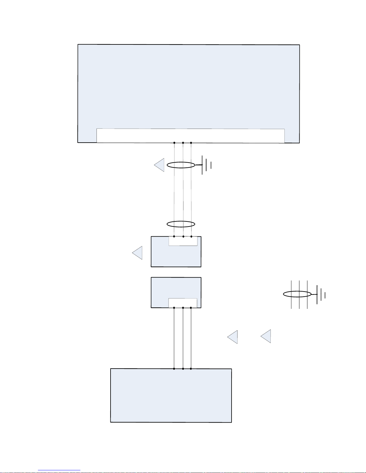
Wiring Diagrams

2010-04-20 P/N: 240-0008-00-02
Copyright 2009-2010 NavWorx ® Page 37 of 46 All rights reserved. Printed in the U.S.A.

2010-04-20 P/N: 240-0008-00-02
Copyright 2009-2010 NavWorx ® Page 38 of 46 All rights reserved. Printed in the U.S.A.
2010-04-20 P/N: 240-0008-00-02
Copyright 2009-2010 NavWorx ® Page 39 of 46 All rights reserved. Printed in the U.S.A.
ADS
600
Maintenance Port TX
Maintenance Port RX
Maintenance Port Ground
P
1
3
4
22
DB
9
Female
Connector
3
2
5
NOTES
:
1
.
ALL WIRES
24
AWG OR LARGER UNLESS OTHERWISE SPECIFIED
.
WIRING FOR MAINTENANCE PORT IS REQUIRED
.
RS
232
PORT
SETTINGS
:
115200
BAUD
,
8
-
BIT
,
NO PARITY
,
1
-
STOP BIT
,
NO FLOW
CONTROL
.
MOUNT THE MAINTENANCE PORT IN AN ACCESSIBLE
LOCATION
.
IT WILL BE CONNECTED TO A PC DURING PROGRAMMING
AND SYSTEM TESTING
.
THE MAXIMUM LENGTH OF THIS CABLE IS
25
FEET
.
GROUNDING PIGTAILS MUST NOT EXCEED
4
INCHES IN LENGTH
.
2
2
Maintenance Port
3
3
ADS
600
Maintenance
(
Serial
)
Port to
Computer Interconnect Diagram
TWISTED SHIELDED THREE
CONDUCTOR SHIELD
TERMINATED TO GROUND
DB
9
Male
Connector
3
2
5
Computer

2010-04-20 P/N: 240-0008-00-02
Copyright 2009-2010 NavWorx ® Page 40 of 46 All rights reserved. Printed in the U.S.A.
ADS600
NOTES:
1. ALL WIRES 24 AWG OR LARGER UNLESS OTHERWISE SPECIFIED.
2. P1: 37-PIN D-SUB, MALE CONNECTOR.
Composite-TIS™
Interconnect Diagram
GTX330
429 In 1B
429 In 1A
ARINC 429 Out 2B
ARINC 429 Out 2A
28
9
28
30
TWISTED SHIELDED TWO
CONDUCTOR SHIELD
TERMINATED TO GROUND
P1
In addition to receiving and processing ADS-B
FIS-B and TIS-B messages, the ADS600 may be
configured for Composite-TIS™. In this
configuration, the ADS600 outputs both TIS-A
and TIS-B traffic to a compatible display: traffic is
the combination of TIS-A targets (from a Mode-S
transponder) when in Mode-S coverage, as well
as TIS-B targets when in ADS-B coverage.

2010-04-20 P/N: 240-0008-00-02
Copyright 2009-2010 NavWorx ® Page 41 of 46 All rights reserved. Printed in the U.S.A.

2010-04-20 P/N: 240-0008-00-02
Copyright 2009-2010 NavWorx ® Page 42 of 46 All rights reserved. Printed in the U.S.A.
ADS600
NOTES:
1. ALL WIRES 24 AWG OR LARGER UNLESS OTHERWISE SPECIFIED.
GROUNDING PIGTAILS MUST NOT EXCEED 4 INCHES IN LENGTH.
GNS 480 ARINC 429 #1 OUT (P5-4/24) MAY BE USED INSTEAD OF
429 #2 (P5-5/25) OUT.
2
3
P1: 37-PIN D-SUB, MALE CONNECTOR
GNS 480 ARINC 743A Position Source
GNS 480
429 In 1B
429 In 1A
ARINC 429 Out 2B
ARINC 429 Out 2A
28
9
P5-25
P5-5
TWISTED SHIELDED TWO
CONDUCTOR SHIELD
TERMINATED TO GROUND
2
743A Time Mark In +
743A Time Mark In -
21P1-19
P1-17
Time Mark Out +
Time Mark Out -
3
2

2010-04-20 P/N: 240-0008-00-02
Copyright 2009-2010 NavWorx ® Page 43 of 46 All rights reserved. Printed in the U.S.A.
ADS600
Maintenance Port TX
Maintenance Port RX
Maintenance Port Ground
P1
3
4
22
DB9 Female
Connector
3
2
5
NOTES:
1. ALL WIRES 24 AWG OR LARGER UNLESS OTHERWISE SPECIFIED.
POWER AND GROUND USE 20 AWG WIRE.
WIRING FOR MAINTENANCE PORT IS REQUIRED. RS232 PORT
SETTINGS: 115200 BAUD, 8-BIT, NO PARITY, 1-STOP BIT. MOUNT THE
MAINTENANCE PORT IN AN ACCESSIBLE LOCATION. IT WILL BE
CONNECTED TO A PC DURING PROGRAMMING AND SYSTEM
TESTING. THE MAXIMUM LENGTH OF THIS CABLE IS 25 FEET.
GROUNDING PIGTAILS MUST NOT EXCEED 4 INCHES IN LENGTH.
THE RECOMMENDED CIRCUIT BREAKER RATING IS 3A FOR
14VDC INSTALLATIONS AND, 2A FOR 28VDC INSTALLATIONS. CIRCUIT
BREAKER SHOULD BE LABELED “UAT”
233
Maintenance Port
4
4
P1
5
3/2 AMP
AVIONICS BUS
(14/28 VDC)
AIRCRAFT
GROUND
18
19
Power +
Power +
2
UAT
P1: 37-PIN D-SUB, MALE CONNECTOR
P2: TNC COAXIAL CONNECTOR (UAT ANTENNA)
P3: TNC COAXIAL CONNECTOR (GPS ANTENNA)
P2
P3
GPS
UAT
Top GPS Antenna
Bottom UAT Antenna
RG400
RG400
6
7
20AWG
20AWG
20AWG
20AWG
GNS 480 Traffic (ARINC 429)
GNS 480
ARINC 429 In 3B
ARINC 429 In 3A
8
27
P5-29
P5-9
THE GPS ANTENNA COAXIAL CABLE LOSS, INCLUDING
CONNECTORS, MUST BE LESS THAN 10dB.
THE UAT ANTENNA COAXIAL CABLE LOSS, INCLUDING
CONNECTORS, MUST BE LESS THAN 3dB. LIMIT THE RG400 CABLE
LENGTH TO 15 FEET.
IF THE ARINC 429 TRAFFIC OPTION IS CONFIGURED FOR THE
GNS 480, THE GNS 480 SERIAL TIS OPTION IS NOT AVAILABLE.
5
6
7
8
TWISTED SHIELDED TWO
CONDUCTOR SHIELD
TERMINATED TO GROUND
TWISTED SHIELDED THREE
CONDUCTOR SHIELD
TERMINATED TO GROUND
Power Ground 37
Power Ground 36
429 Out 1A
429 Out 1B
8
Altitude
Encoder
TX
Ground
Altitude Encoder RX
Altitude Encoder Ground
7
6
4
***ALTITUDE ENCODER INPUT REQUIRED***

2010-04-20 P/N: 240-0008-00-02
Copyright 2009-2010 NavWorx ® Page 44 of 46 All rights reserved. Printed in the U.S.A.
ADS600
Maintenance Port TX
Maintenance Port RX
Maintenance Port Ground
P1
3
4
22
DB9 Female
Connector
325
NOTES:
1. ALL WIRES 24 AWG OR LARGER UNLESS OTHERWISE SPECIFIED.
POWER AND GROUND USE 20 AWG WIRE.
WIRING FOR MAINTENANCE PORT IS REQUIRED. RS232 PORT
SETTINGS: 115200 BAUD, 8-BIT, NO PARITY, 1-STOP BIT. MOUNT THE
MAINTENANCE PORT IN AN ACCESSIBLE LOCATION. IT WILL BE
CONNECTED TO A PC DURING PROGRAMMING AND SYSTEM
TESTING. THE MAXIMUM LENGTH OF THIS CABLE IS 25 FEET.
GROUNDING PIGTAILS MUST NOT EXCEED 4 INCHES IN LENGTH.
THE RECOMMENDED CIRCUIT BREAKER RATING IS 3A FOR
14VDC INSTALLATIONS AND, 2A FOR 28VDC INSTALLATIONS. CIRCUIT
BREAKER SHOULD BE LABELED “UAT”
233
Maintenance Port
4
4
P1
5
3/2 AMP
AVIONICS BUS
(14/28 VDC)
AIRCRAFT
GROUND
18
19
Power +
Power +
2
UAT
P1: 37-PIN D-SUB, MALE CONNECTOR
P2: TNC COAXIAL CONNECTOR (UAT ANTENNA)
P3: TNC COAXIAL CONNECTOR (GPS ANTENNA)
P2
P3
GPS
UAT
Top GPS Antenna
Bottom UAT Antenna
RG400
RG400
6
7
20AWG
20AWG
20AWG
20AWG
GNS 480 Traffic (RS-232 TIS)
GNS 480
RS232 RxD6
6
25
P5-42
P5-2
THE GPS ANTENNA COAXIAL CABLE LOSS, INCLUDING
CONNECTORS, MUST BE LESS THAN 10dB.
THE UAT ANTENNA COAXIAL CABLE LOSS, INCLUDING
CONNECTORS, MUST BE LESS THAN 3dB. LIMIT THE RG400 CABLE
LENGTH TO 15 FEET.
IF THE SERIAL TIS OPTION IS CONFIGURED FOR THE GNS 480,
THE GNS 480 ARINC 429 TRAFFIC OPTION IS NOT AVAILABLE. TISA AND ALTITUDE ENCODER INPUT SHARE THE SAME
GROUND PIN, P1-6.
10. REFER TO COMPOSITE-TIS™ DIAGRAM FOR WIRING REQUIRED
FOR COMPOSITE-TIS.
5
6
7
8
TWISTED SHIELDED TWO
CONDUCTOR SHIELD
TERMINATED TO GROUND
TWISTED SHIELDED THREE
CONDUCTOR SHIELD
TERMINATED TO GROUND
Power Ground 37
Power Ground 36
TIS TX
TIS Ground
Serial Ground 6
8
Altitude
Encoder
TX
Ground
Altitude Encoder RX
Altitude Encoder Ground
7
6
4
9
***ALTITUDE ENCODER INPUT REQUIRED***
9
9

2010-04-20 P/N: 240-0008-00-02
Copyright 2009-2010 NavWorx ® Page 45 of 46 All rights reserved. Printed in the U.S.A.
ADS600
Maintenance Port TX
Maintenance Port RX
Maintenance Port Ground
P1
3
4
22
Chelton Serial
Port 3
DB9 Female
Connector
3
2
5
NOTES:
1. ALL WIRES 24 AWG OR LARGER UNLESS OTHERWISE SPECIFIED.
POWER AND GROUND USE 20 AWG WIRE.
WIRING FOR MAINTENANCE PORT IS REQUIRED. RS232 PORT
SETTINGS: 115200 BAUD, 8-BIT, NO PARITY, 1-STOP BIT. MOUNT THE
MAINTENANCE PORT IN AN ACCESSIBLE LOCATION. IT WILL BE
CONNECTED TO A PC DURING PROGRAMMING AND SYSTEM
TESTING. THE MAXIMUM LENGTH OF THIS CABLE IS 25 FEET.
GROUNDING PIGTAILS MUST NOT EXCEED 4 INCHES IN LENGTH.
THE RECOMMENDED CIRCUIT BREAKER RATING IS 3A FOR
14VDC INSTALLATIONS AND, 2A FOR 28VDC INSTALLATIONS. CIRCUIT
BREAKER SHOULD BE LABELED “UAT”
233
Maintenance Port
4
4
P1
4
5
3/2 AMP
AVIONICS BUS
(14/28 VDC)
AIRCRAFT
GROUND
18
19
Power +
Power +
2
UAT
P1: 37-PIN D-SUB, MALE CONNECTOR
P2: TNC COAXIAL CONNECTOR (UAT ANTENNA)
P3: TNC COAXIAL CONNECTOR (GPS ANTENNA)
P2
P3
GPS
UAT
Top GPS Antenna
Bottom UAT Antenna
RG400
RG400
6
7
20AWG
20AWG
20AWG
20AWG
ADS600 to Chelton
ADS-B
8
THE GPS ANTENNA COAXIAL CABLE LOSS,
INCLUDING CONNECTORS, MUST BE LESS THAN
10dB.
THE UAT ANTENNA COAXIAL CABLE LOSS,
INCLUDING CONNECTORS, MUST BE LESS THAN
3dB. LIMIT THE RG400 CABLE LENGTH TO 15 FEET.
IN THIS CONFIGURATION, THE CHELTON
DISPLAY IS SET TO RECEIVE ADS-B SO THAT BOTH
TIS-B AND FIS-B DATA ARE PROVIDED THROUGH
CHELTON’S ADS-B/WSI INPUT. THIS RESTRICTS THE
CHELTON UNIT TO ONLY ADS-B CAPABILITIES.
REFER TO THE “ADS600 TO CHELTON COMPOSITE-
TIS™” DIAGRAM FOR A CONFIGURATION THAT
ALLOWS THE CHELTON TO BE CONFIGURED TO
USE WSI WX WITH COMPOSITE-TIS™.
5
6
7
8
TWISTED SHIELDED TWO
CONDUCTOR SHIELD
TERMINATED TO GROUND
TWISTED SHIELDED THREE
CONDUCTOR SHIELD
TERMINATED TO GROUND
Power Ground 37
Power Ground 36
5 Display TX
23 Ground
RS232 Datalink RX 3
Ground 24
Altitude
Encoder
TX
Ground
Altitude Encoder RX
Altitude Encoder Ground
7
6
4
***ALTITUDE ENCODER INPUT REQUIRED***
RS232 Datalink TX 45
24 Display RX
J1
CHELTON CONFIGURATON
On the “Factory Programmed Settings” page in the Chelton Limits Setup:
Datalink Receiver = ADS-B

2010-04-20 P/N: 240-0008-00-02
Copyright 2009-2010 NavWorx ® Page 46 of 46 All rights reserved. Printed in the U.S.A.
ADS600
Maintenance Port TX
Maintenance Port RX
Maintenance Port Ground
P1
3
4
22
Chelton Serial
Port 5
DB9 Female
Connector
325
NOTES:
1. ALL WIRES 24 AWG OR LARGER UNLESS OTHERWISE SPECIFIED.
POWER AND GROUND USE 20 AWG WIRE.
WIRING FOR MAINTENANCE PORT IS REQUIRED. RS232 PORT
SETTINGS: 115200 BAUD, 8-BIT, NO PARITY, 1-STOP BIT. MOUNT THE
MAINTENANCE PORT IN AN ACCESSIBLE LOCATION. IT WILL BE
CONNECTED TO A PC DURING PROGRAMMING AND SYSTEM
TESTING. THE MAXIMUM LENGTH OF THIS CABLE IS 25 FEET.
GROUNDING PIGTAILS MUST NOT EXCEED 4 INCHES IN LENGTH.
THE RECOMMENDED CIRCUIT BREAKER RATING IS 3A FOR
14VDC INSTALLATIONS AND, 2A FOR 28VDC INSTALLATIONS. CIRCUIT
BREAKER SHOULD BE LABELED “UAT”
233
Maintenance Port
4
4
P1
4
5
3/2 AMP
AVIONICS BUS
(14/28 VDC)
AIRCRAFT
GROUND
18
19
Power +
Power +
2
UAT
P1: 37-PIN D-SUB, MALE CONNECTOR
P2: TNC COAXIAL CONNECTOR (UAT ANTENNA)
P3: TNC COAXIAL CONNECTOR (GPS ANTENNA)
P2
P3
GPS
UAT
Top GPS Antenna
Bottom UAT Antenna
RG400
RG400
6
7
20AWG
20AWG
20AWG
20AWG
ADS600 to Chelton
Composite-TIS™
8
THE GPS ANTENNA COAXIAL CABLE LOSS,
INCLUDING CONNECTORS, MUST BE LESS THAN
10dB.
THE UAT ANTENNA COAXIAL CABLE LOSS,
INCLUDING CONNECTORS, MUST BE LESS THAN
3dB. LIMIT THE RG400 CABLE LENGTH TO 15
FEET.
IN THIS CONFIGURATION, THE ADS600
OUTPUTS BOTH TIS-A AND TIS-B (COMPOSITE-
TIS™) TRAFFIC TO THE CHELTON DISPLAY:
TRAFFIC IS THE COMBINATION OF TIS-A
TARGETS (FROM THE GTX330 TRANSPONDER)
WHEN IN MODE-S COVERAGE, AS WELL AS TIS-B
TARGETS WHEN IN ADS-B COVERAGE. WITH
THIS CONFIGURATION THE CHELTON DISPLAY
DOES NOT RECEIVE FIS-B (WEATHER) FROM
THE ADS600. TO CONFIGURE THE CHELTON TO
RECEIVE FIS-B, REFER TO THE “ADS600 TO
CHELTON ADS-B” DIAGRAM.
5
6
7
8
TWISTED SHIELDED TWO
CONDUCTOR SHIELD
TERMINATED TO GROUND
TWISTED SHIELDED THREE
CONDUCTOR SHIELD
TERMINATED TO GROUND
Power Ground 37
Power Ground 36
25 TISA TX
23 Ground
RS232 TAS RX 5
Ground 26
Altitude
Encoder
TX
Ground
Altitude Encoder RX
Altitude Encoder Ground
7
6
4
***ALTITUDE ENCODER INPUT REQUIRED***
RS232 TAS TX 47
24 Display RX
J1
GTX330
429 In 1B
429 In 1A
ARINC 429 Out 2B
ARINC 429 Out 2A
28
9
28
30
CHELTON CONFIGURATON
On the “Factory Programmed Settings” page in the Chelton Limits Setup:
Datalink Receiver = WSI (if equipped)
Traffic Sensor = TCAS-I(ARINC429)
On the “ARINC429 Receive Port Settings” page in the Chelton Limits Setup:
COM23 should be set to HI speed and all columns turned OFF except for TCAS which is ON.
Note that the GTX330 provides ARINC labels for TCAS-I type function to the Chelton using 38,400 baud RS-232 connection.
 Loading...