

Page 1
GM UNI-CAM/UNI-CAM PRG
RVC controller interface &/or programmer for select GM vehicles equipped with MyLink IOH Radio
IOH = IO4 (4” screen) & IO5/IO6 (8” screen)
NTV-KIT629: Controller ONLY (for vehicles with OEM RVC)
NTV-KIT630: Controller & Programmer (for vehicles without OEM RVC)
BHM
09/26/17
NTV-DOC239
3950 NW 120
th
Ave, Coral Springs, FL 33065 TEL 561-955-9770 FAX 561-955-9760
Page 2
BHM
09/26/17
NTV-DOC239
Agreement: End user agrees to use this product in compliance with all State and Federal laws. NAV-TV Corp. would not be held liable for misuse of its product.
If you do not agree, please discontinue use immediately and return product to place of purchase. This product is intended for off-road use and passenger
entertainment only.
2 | P a g e
Overview
The GM UNI-CAM adds an additional video input on select GM vehicles equipped with the MyLink (model IOH)
4” and 8” color media screens. Forcing (aftermarket) AUX Video or front camera to display at any time is
activated with wire triggers. Note: NTV-KIT629 is a controller only, it will NOT program the MyLink radio
system for rear camera. If adding a reverse camera to a vehicle without OEM RVC and forced cam/AUX video
input is desired as well, you must purchase NTV-KIT630 (UNI-CAM with built-in programmer).
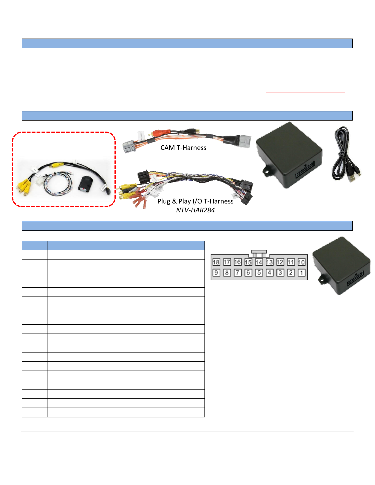
Kit Content
GM UNI-CAM Pinout
Pin #
Description
Color
1
12v Constant Power (+)
Yellow
2
Input 1 (Force Rear Cam)*
Red
3
Input 2 (Force Front Cam)
Blue
4
Input 3 (4” Programming Wire)**
Pink 5 --NOT USED--
Brown
6
RCA Signal (+) (Out to radio)
Yellow
7
RCA Shield (common)
Gray
8
CAN HI (HMI side)
White/Blue
9
CAN LO (vehicle side)
White/Brown
10
Ground (-)
Black
11
Output 1 (ACC 12v +)
White/Red
12
Output 2 (REV 12v + & FRVC)
White/Blue
13
Output 3 (12v + out when FFVC)
White/Purple
14
--Not Used--
White/Brown
15
RCA Signal (+) Input (front cam)
White
16
RCA Signal (+) Input (rear cam)
Red
17
CAN HI (HMI side)
Blue
18
CAN LO (vehicle side)
Brown
Wire Side
Any wires not mentioned here are not used for
this installation.
GM UNI-CAM Module
KIT629: NTV-ASY166
USB Cable
(updates)
NTV-CAB009
*Forcing rear camera is only available for
aftermarket cameras (unless OEM rear camera
is powered with an ACC source or OUTPUT 2
manually – OEM RVC normally only powered in
reverse)
**Used for (IO4) 4” screens ONLY.
Plug & Play I/O T-Harness
NTV-HAR284
CAM T-Harness
NTV-HAR283
VSW-R included with
NTV-KIT629
PIN 12 FRVC: ‘Forced Rear View Camera’
PIN 13 FFVC: ‘Forced Front View Camera’
Page 3
BHM
09/26/17
NTV-DOC239
Agreement: End user agrees to use this product in compliance with all State and Federal laws. NAV-TV Corp. would not be held liable for misuse of its product.
If you do not agree, please discontinue use immediately and return product to place of purchase. This product is intended for off-road use and passenger
entertainment only.
3 | P a g e
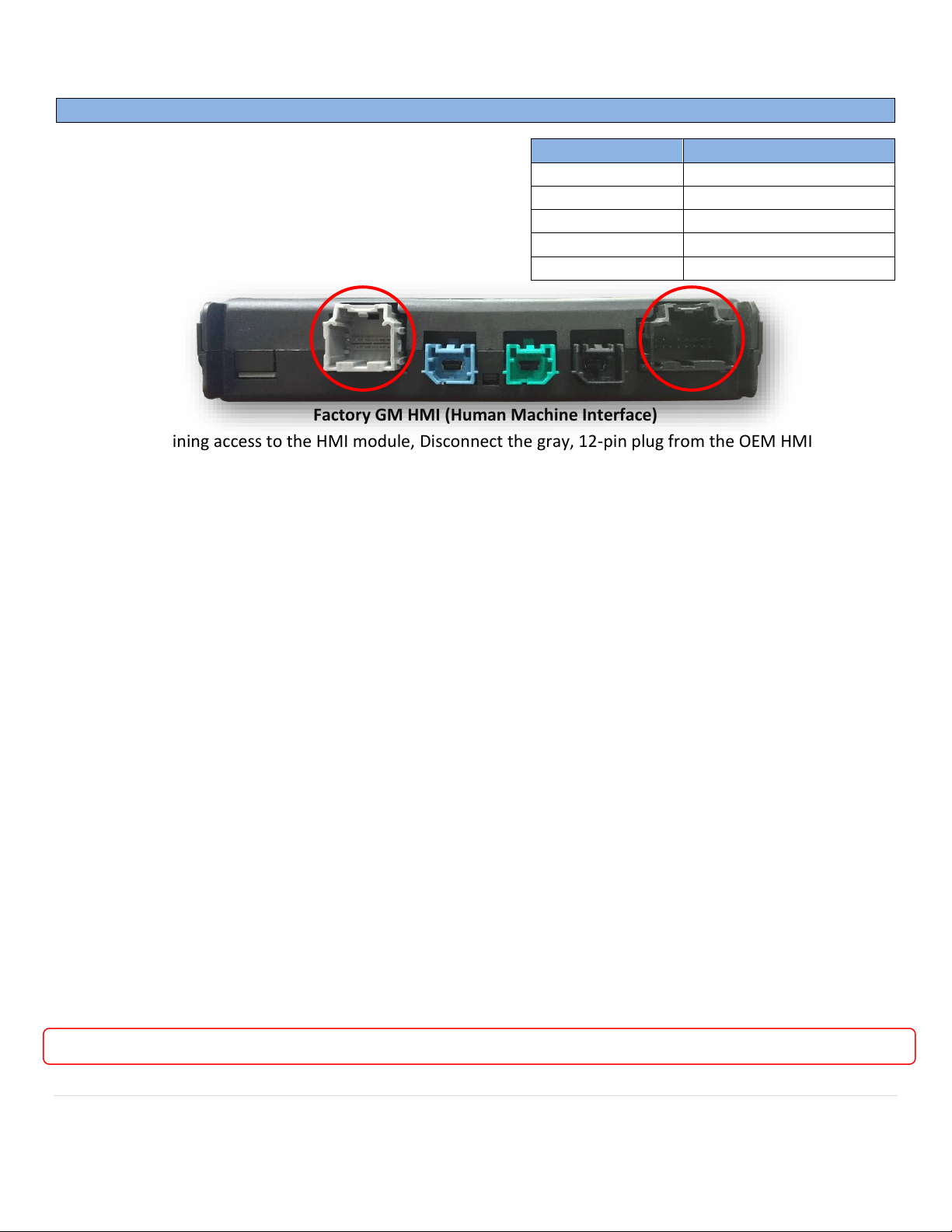
Known HMI
Locations:
GM UNI-CAM Installation
1. After gaining access to the HMI module, Disconnect the gray, 12-pin plug from the OEM HMI circled
above.
2. Disconnect the black, 16-pin plug from the OEM HMI circled above.
3. Connect the provided UNI-CAM 12-pin & 16-pin (male end) connectors into the HMI plug locations
from steps 1 & 2.
4. Connect the factory 12-pin & 16-pin plugs (previously connected to the HMI) into the provided Plug &
Play T-Harness (female end).
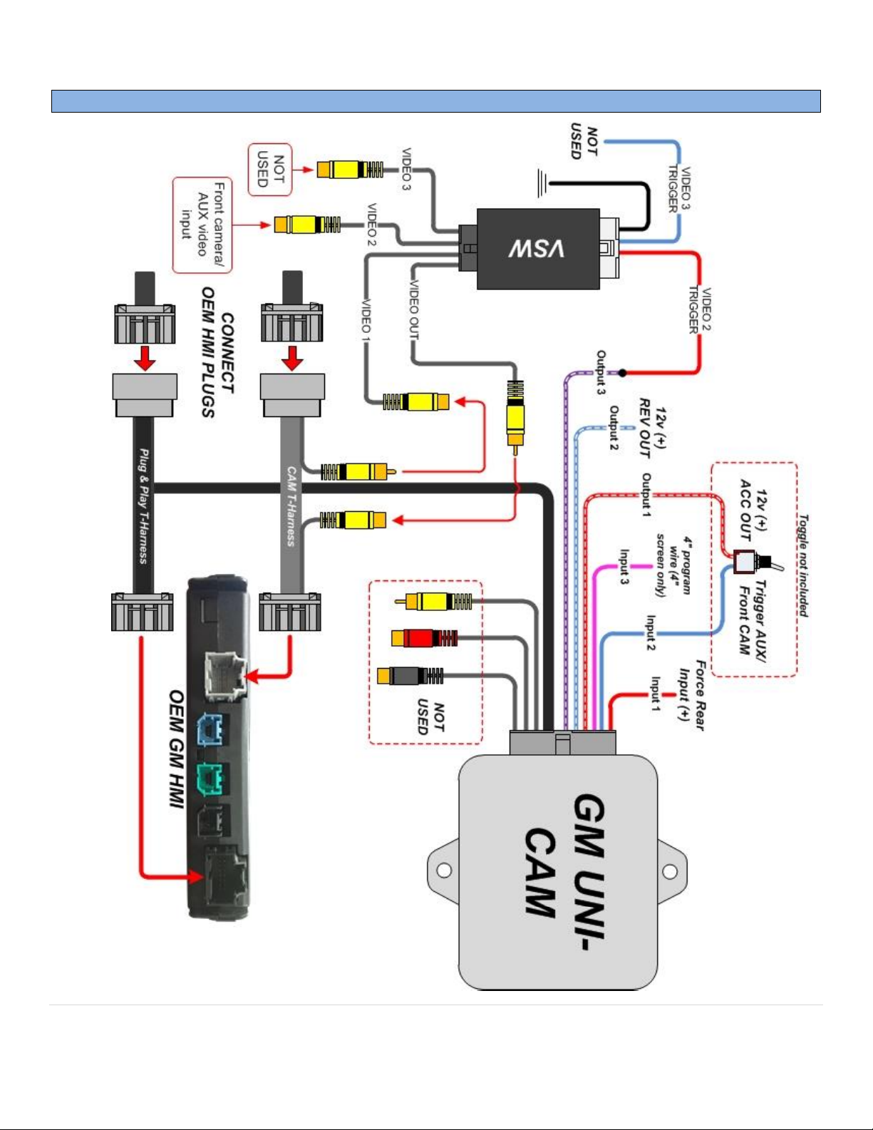
5. NTV-KIT629 Installation (with existing OEM reverse camera):
a. When connecting a front camera (or AUX video source) to a vehicle with an existing OEM
reverse camera, the internal relay on the UNI-CAM board is not used (RCA I/Os from module).
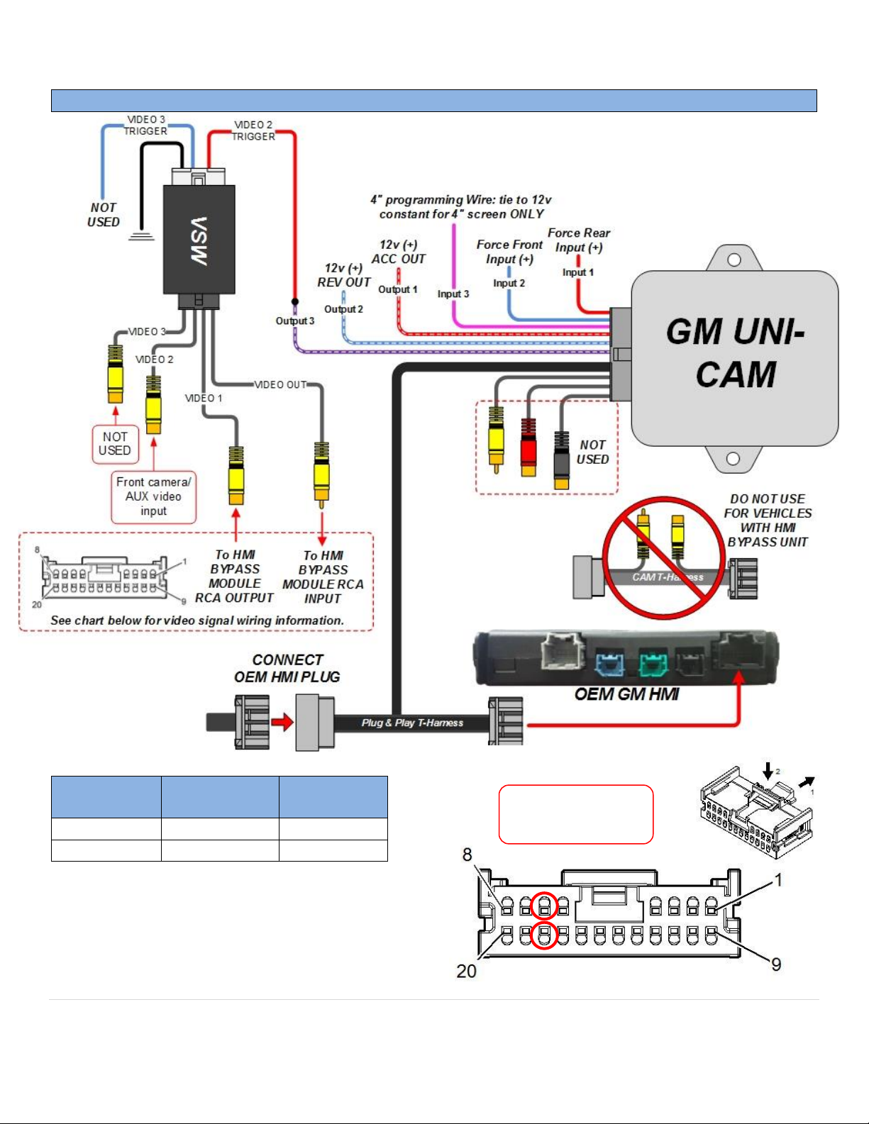
Complete all connections on page 5 (FIG 2) using the included VSW-R (included with KIT629) to
prevent ‘bleed-over’ image (when in front camera mode). This includes the following:
b. Black wire of VSW to chassis ground
c. OUTPUT 3 (from module) to White/Red of VSW
d. RCA connections as shown in diagram (FIG 2)
e. Continue with installation on page 4, step 7.
6. NTV-KIT630 Installation (without existing OEM reverse camera):
a. Adding a single rear camera: power your camera with an ACC source or OUTPUT 1 (especially if
using the forced feature), and connect your camera signal directly to the female RCA (into the
HMI) from the 12-pin gray plug.
b. Adding 2 aftermarket cameras: Instead of connecting camera signal directly to the HMI,
connect the RVC signal to the RCA labeled ‘BACKUP CAM’ at the UNI-CAM module. Connect the
front cam/AUX video to the RCA labeled ‘FRONT CAM’. Connect the (male) ‘VIDEO OUT’ RCA to
the female RCA from the CAM T-Harness (at the HMI). Leave the male RCA on the CAM THarness disconnected.
c. If this vehicle is equipped with a 4” screen, connect INPUT 3 (pink) to a CONSTANT 12v source.
d. Continue with installation on step 7 (next page).
Vehicle
HMI Location
Cadillac ATS/CTS
Directly below glove box
Cadillac SRX
Below/behind glove box
Corvette
Driver’s kick panel
Silverado/Sierra
Behind glove box - high
Colorado/Canyon
Behind Screen - low
Factory GM HMI (Human Machine Interface)
The UNI-CAM kit connects at the OEM
HMI Module. The location of this module
varies by vehicle.
NOTE: If this wire is not connected, the UNI-CAM PRG will program for 8” screen (image will appear zoomed in).
Page 4
BHM
09/26/17
NTV-DOC239
Agreement: End user agrees to use this product in compliance with all State and Federal laws. NAV-TV Corp. would not be held liable for misuse of its product.
If you do not agree, please discontinue use immediately and return product to place of purchase. This product is intended for off-road use and passenger
entertainment only.
4 | P a g e
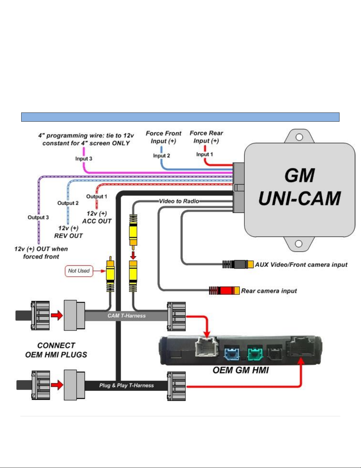
7. Optional: Connect INPUT 1 &/or INPUT 2 to an ACC 12v (+) source through toggles for displaying rear
view camera and front view camera (or AUX video) at any time.
NOTE: the factory GM screen may generate parking guidelines (while in reverse), which can be
turned off in the OEM settings (through radio). This is usually required when using the UNI-CAM
for an additional AUX video input (DVD player, etc).
8. Connect the UNI-CAM module to the 18-pin plug located on the Plug & Play T-Harness.
9. KIT630 ONLY: Proceed to UNI-CAM Programming. Note: If vehicle already possesses a rear camera,
this programming step is not needed!
GM UNI-CAM Diagram (adding aftermarket cameras)
FIG 1
Page 5
BHM
09/26/17
NTV-DOC239
Agreement: End user agrees to use this product in compliance with all State and Federal laws. NAV-TV Corp. would not be held liable for misuse of its product.
If you do not agree, please discontinue use immediately and return product to place of purchase. This product is intended for off-road use and passenger
entertainment only.
5 | P a g e
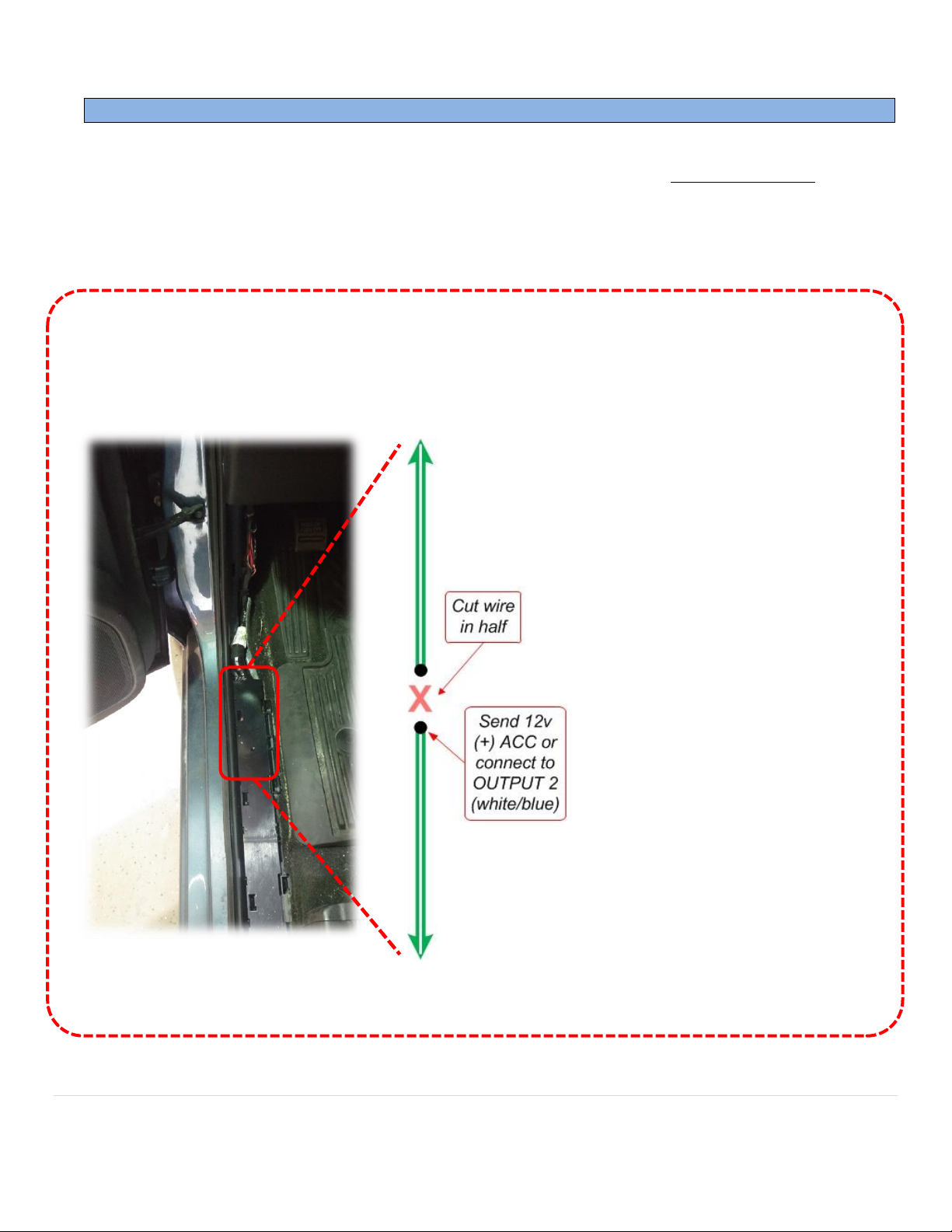
GM UNI-CAM Installation (adding AUX video with existing OEM RVC)
FIG 2
Page 6
BHM
09/26/17
NTV-DOC239
Agreement: End user agrees to use this product in compliance with all State and Federal laws. NAV-TV Corp. would not be held liable for misuse of its product.
If you do not agree, please discontinue use immediately and return product to place of purchase. This product is intended for off-road use and passenger
entertainment only.
6 | P a g e
GM UNI-CAM Installation: Force OEM rear camera (up to 2016 vehicles)
• NOTE: pages 6 & 7 illustrate wiring modification for forcing OEM cameras for up to 2016 vehicles. In 2017+
vehicles, for determining whether or not this vehicle has an HMI Bypass Module, see page 8. Then, for
forcing OEM rear camera on 2017+ vehicles with an OEM HMI Bypass Module, see page 10.
• NOTE: If adding an aftermarket rear camera to any year vehicle, these steps are not required.
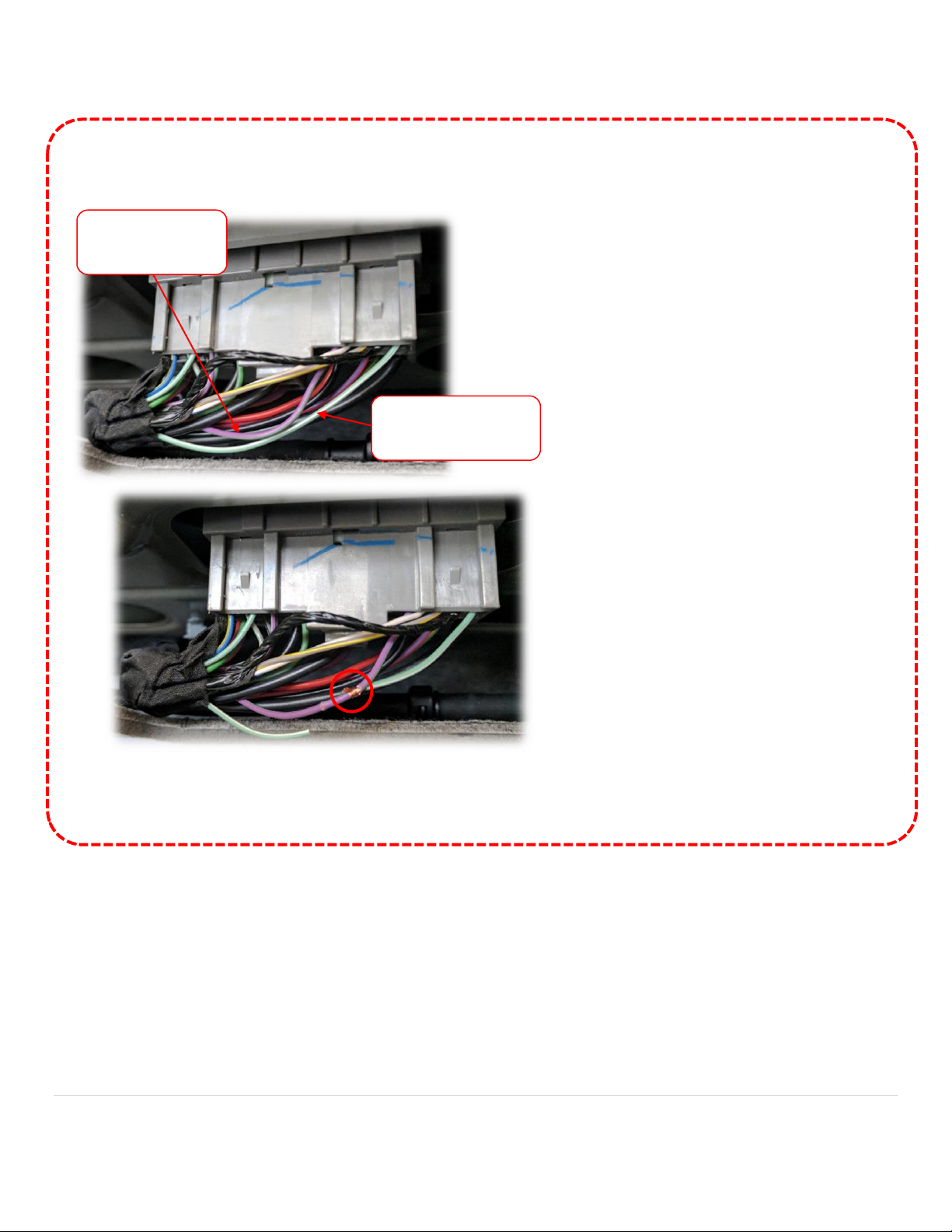
10. Optional (up to 2016 pickup trucks): If the user wishes to force the OEM Reverse camera at any time,
you must power the OEM camera power wire manually. Complete the connection shown in the diagram
below.
NOTE: This example diagram is for
2016 GM truck. Other vehicles may
have a different color wire. Always
test wire before modifying.
From
BCM
Installation Procedure:
1. Locate, test green/white
OEM RVC power wire and
cut in HALF. Wire will
show 12v (+) when in
reverse (engine must be
running)
2. Extend a 12v (+) ACC wire
(or OUTPUT 2) and
connect to camera side as
shown.
3. Isolate BCM side of cut
wire.
Location: driver’s sill or kick panel,
harness that runs to rear
To OEM Reverse
Camera
Page 7
BHM
09/26/17
NTV-DOC239
Agreement: End user agrees to use this product in compliance with all State and Federal laws. NAV-TV Corp. would not be held liable for misuse of its product.
If you do not agree, please discontinue use immediately and return product to place of purchase. This product is intended for off-road use and passenger
entertainment only.
7 | P a g e
11. Optional (up to 2016 SUVs): If the user wishes to force the OEM Reverse camera at any time, you must
power the OEM camera power wire manually. Complete the connection shown in the diagram below.
NOTE: This example diagram is for
GM SUV. Other vehicles may have a
different color wire. Always test wires
before modifying.
Modification Procedure:
1. Locate, test green/white OEM
RVC power wire at the tail-gate
harness connector and cut in HALF.
Wire will show 12v (+) when in
reverse (engine must be running)
2. Connect the camera side (lift gate
side) of the cut wire to the
purple/green ACC wire.
3. Isolate BCM side (front of vehicle
side) of cut wire.
Location: Back of truck, lift gate open, top center
connector from vehicle to lift gate (in headliner)
ACC wire:
(Purple/Green)
RVC power wire:
(Green/White)
Page 8
BHM
09/26/17
NTV-DOC239
Agreement: End user agrees to use this product in compliance with all State and Federal laws. NAV-TV Corp. would not be held liable for misuse of its product.
If you do not agree, please discontinue use immediately and return product to place of purchase. This product is intended for off-road use and passenger
entertainment only.
8 | P a g e
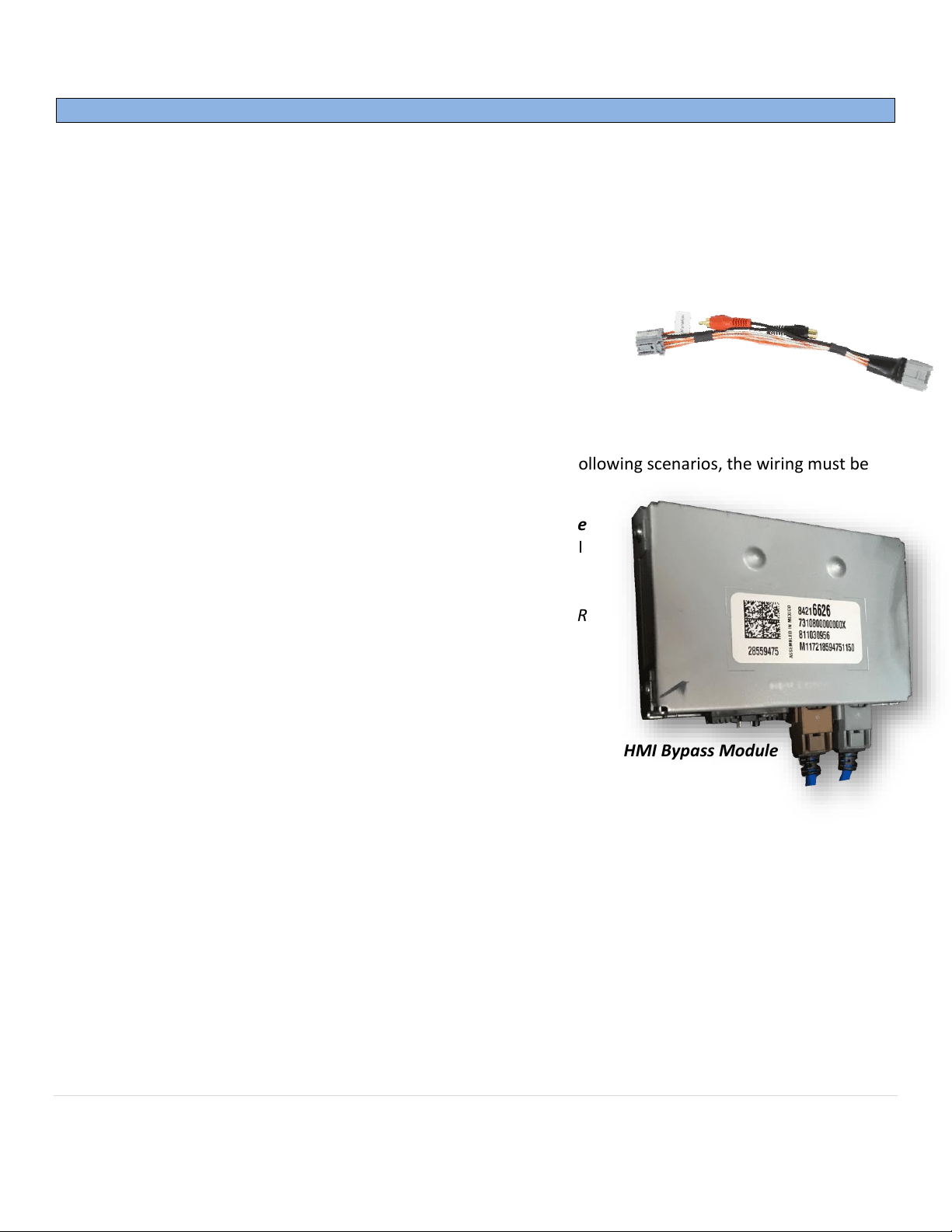
GM UNI-CAM Installation (2017+ with OEM HMI Bypass Module ONLY)
The following page only applies to 2017+ vehicles equipped with an OEM rear camera.
• In some compatible 2017+ vehicles, the system is equipped with an additional module called the ‘HMI
Bypass Module’ which routes LVDS and camera images to the screen from the HMI. If equipped, the
module is normally located directly beneath the BCM (driver’s side under dash).
• A quick easy way to test for the presence of the HMI Bypass Module:
o Access the OEM HMI unit (see chart on page 3)
o Connect the provided CAM T-Harness in between the 12-
pin plug at the HMI and the vehicle’s 12-pin connector,
connect RCAs together
o Start vehicle. Place vehicle into reverse gear.
o With OEM reverse image on the screen, disconnect the RCAs in the CAM T-Harness.
o If the reverse image remains on screen with the RCA disconnected, this vehicle is equipped
with the HMI Bypass Module. This means that in the following scenarios, the wiring must be
completed differently:
Scenario 1: If introducing AUX video (or front camera) is desired while
in reverse gear, the secondary camera must be connected at the HMI
Bypass Module, instead of at the HMI itself (See FIG 3, next page). If
AUX video is only necessary outside of reverse gear, then you may
connect it normally (FIG 1. NOTE: for these special vehicles, the VSW-R
is not necessary – plug signal directly into the CAM T-Harness).
Scenario 2: If the user wishes to be able to force the OEM tailgate
camera at any time, then a reverse wire must be cut and powered
differently at the vehicle’s BCM. See FIG 4.
HMI Bypass Module
Page 9
BHM
09/26/17
NTV-DOC239
Agreement: End user agrees to use this product in compliance with all State and Federal laws. NAV-TV Corp. would not be held liable for misuse of its product.
If you do not agree, please discontinue use immediately and return product to place of purchase. This product is intended for off-road use and passenger
entertainment only.
9 | P a g e
GM UNI-CAM Installation (HMI Bypass Module only)
• Locate pins 6 & 18, cut these wires in half.
• Connect an RCA cable (male) to the harness side of
the cut wires (according to chart above).
• Connect an RCA (female) to the module side of the
cut wires (according to chart above).
HMI Bypass
PIN #
Description
Typical
Wire Color
6
RVC (+) signal
Gray/Yellow
18
RVC (-) shield
White/Blue
FIG 3
HMI Bypass
Module 20-PIN
Page 10
BHM
09/26/17
NTV-DOC239
Agreement: End user agrees to use this product in compliance with all State and Federal laws. NAV-TV Corp. would not be held liable for misuse of its product.
If you do not agree, please discontinue use immediately and return product to place of purchase. This product is intended for off-road use and passenger
entertainment only.
10 | P a g e
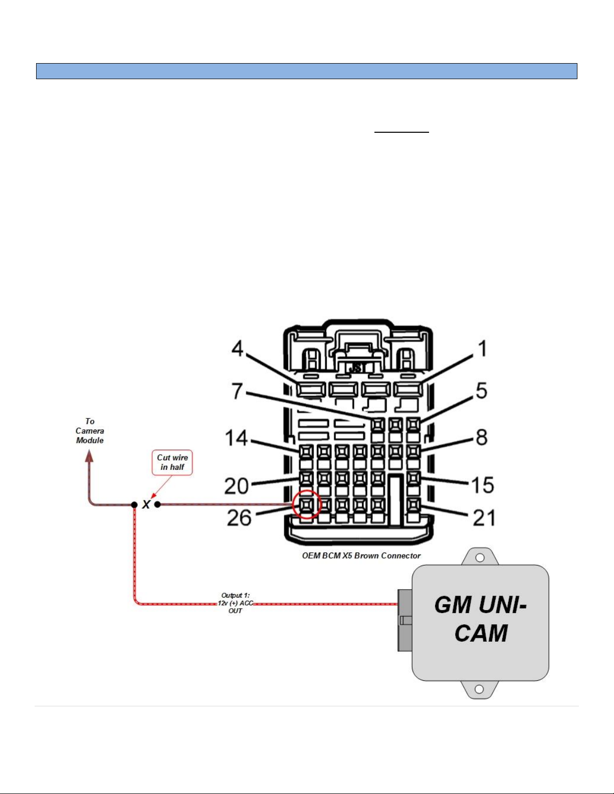
GM UNI-CAM Installation: Forcing OEM camera (2017+ vehicles only)
• For 2017+ vehicles only, those equipped with the HMI Bypass (as discussed on page 8), a reverse
power wire must be cut and supplied with ACC 12v (+) power at the BCM instead in order for forced
OEM rear camera to function properly. NOTE: if adding an aftermarket rear camera, this step is not
needed.
1. Locate the vehicle BCM. For most vehicles, this is underneath the driver’s dashboard, beneath the
steering wheel.
2. On the BCM there are multiple 20-30 pin plugs. Locate the brown, 26-pin plug.
3. In the brown plug, pin 26 (blue/brown) is ‘Backup Lamp Relay Control’. Cut this wire in half.
4. Extend an ACC 12v (+) source (or use Output 1 from the UNI-CAM module) and connect it to the
vehicle side (not BCM side) of the cut wire.
5. Isolate the other end of the cut blue/brown wire.
6. Now, when Input 1 receives 12v (through a toggle), the rear camera will show regardless of gear or
speed.
FIG 4
Page 11
BHM
09/26/17
NTV-DOC239
Agreement: End user agrees to use this product in compliance with all State and Federal laws. NAV-TV Corp. would not be held liable for misuse of its product.
If you do not agree, please discontinue use immediately and return product to place of purchase. This product is intended for off-road use and passenger
entertainment only.
11 | P a g e
GM UNI-CAM Programming (KIT630 ONLY)
1. Once all connections are made, turn the key to the IGNITION ON position. Watch the LED on the UNI-
CAM Module and verify flash codes below.
2. Wait for radio to reboot fully. The radio may reboot more than once – wait a few minutes.
3. Cycle the vehicle key once (turn off, wait 5 seconds, turn back to IGNITION ON)
4. Verify 6 FLASHES from LED on module.
5. Verify that the radio accepted the program properly by placing the vehicle in reverse. The reverse
screen should appear (or black screen if no camera connected yet) when in reverse only.
NOTE: the vehicle may have to be running (engine) for the reverse camera to show (factory limitation)
6. UPDATE: if nothing happens in reverse after
programming, disconnect the 20-pin power
plug (black) at the OEM HMI module, then
reconnect to reset the system manually. Once
the radio has reset and booted fully, test for
rear camera activation again.
IMPORTANT NOTE: There is NO De-Programming option with the GM UNI-CAM. Once programmed, this
system modification will remain forever.
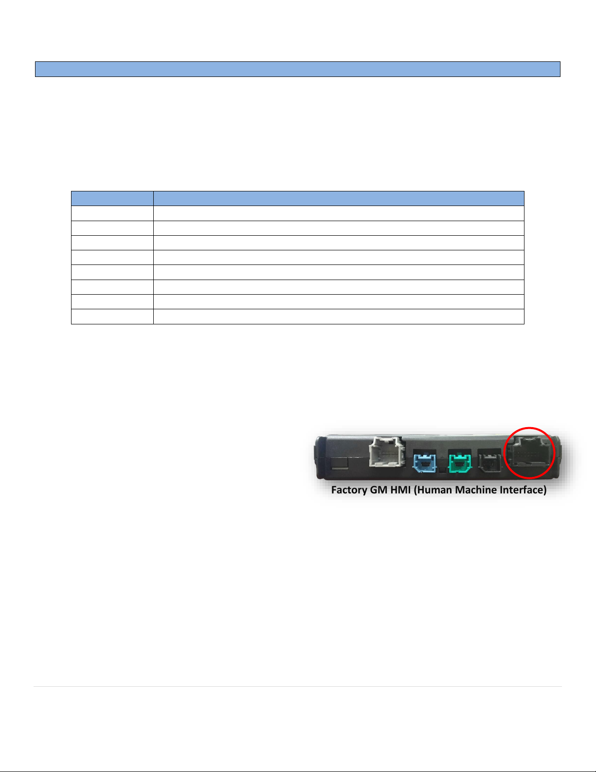
LED Response
Description
1 flash
Waiting for Ignition… (Turn ignition to ON)
2 flashes
Waiting for Vehicle VIN…
3 flashes
Query Vehicle (Reading/decoding the VIN and vehicle components)
4 flashes
Programming…
5 flashes
Programming Complete
6 flashes
No Programming Needed (Already programmed)
7 flashes
Radio Not Supported (Verify this vehicle is equipped with IOH Radio Code)
8 flashes
Out of Licenses (Contact NAV-TV to purchase more licenses)
Programming is complete when the LED flashes 5 times.
Factory GM HMI (Human Machine Interface)
DISCLAIMER: DO NOT disconnect the programmer during programming – this may result in complete radio brick
(factory limitation). NAV-TV is not responsible for failure to comply with this rule.
Page 12
BHM
09/26/17
NTV-DOC239
Agreement: End user agrees to use this product in compliance with all State and Federal laws. NAV-TV Corp. would not be held liable for misuse of its product.
If you do not agree, please discontinue use immediately and return product to place of purchase. This product is intended for off-road use and passenger
entertainment only.
12 | P a g e
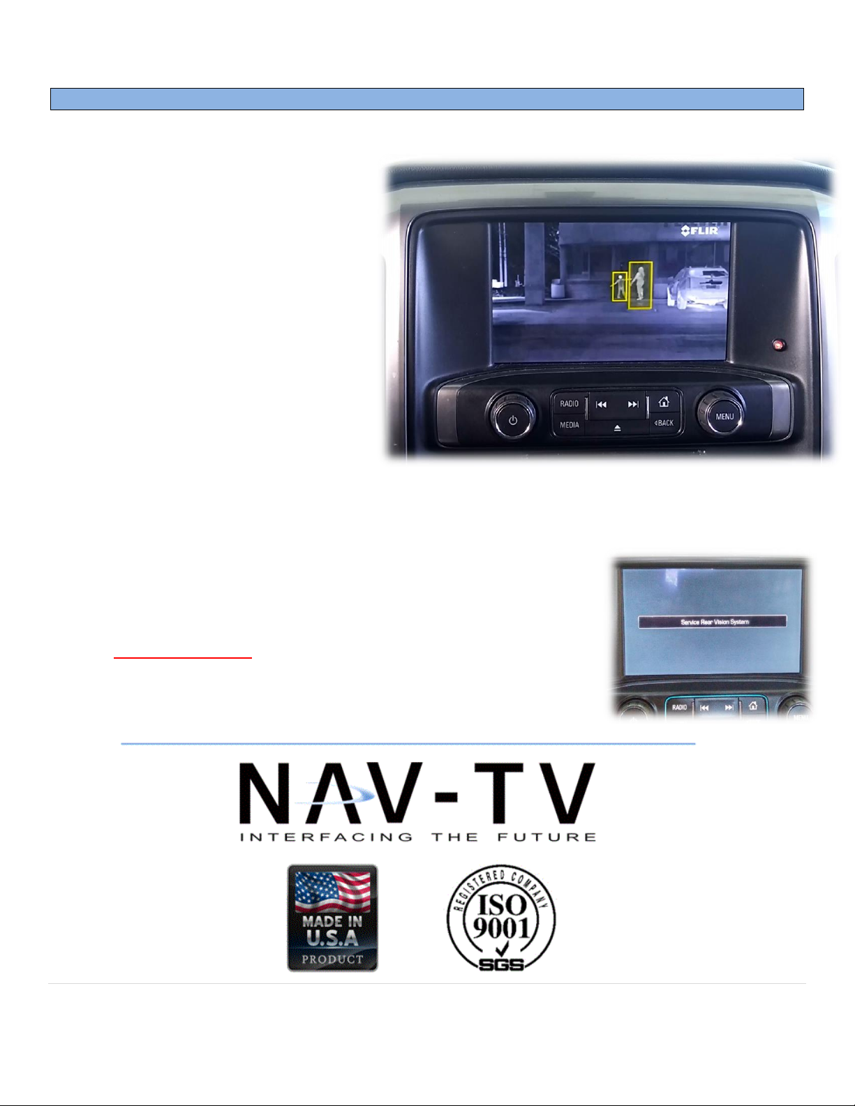
GM UNI-CAM Operation
• After installation/programming is
complete, placing the vehicle in
reverse (with engine running) will
show the connected camera
automatically.
• Sending 12v to INPUT 1 through a
toggle will force the rear camera on at
any time, in any gear.*
• Sending 12v to INPUT 2 through a
toggle will force the front camera (or
aux video) on at any time.
• If Front Camera is active and the
vehicle is placed in reverse, the
reverse image will show (priority).
Once placed back into Drive or Park,
the Front Camera will show again if
still activated.
Note: Once the transmission leaves reverse gear, there may be a ~5 second delay on transitioning back to
the radio screen. This is normal OE operation.
*For aftermarket cameras only. If OEM rear camera forced action is wanted,
the camera must be powered separately (OEM GM rear cameras are normally
powered while in reverse only). See page 6 or 7 for (up to) 2016 vehicles, and
page 10 for 2017+ vehicles.
 Loading...