

NAV-TV UCTv2 + Instruction Manual
UCTv2 +
Dodge/Jeep uConnect (RA3/RA4) Dual Camera & A/V Interface
NTV-KIT763
3950 NW 120
th
Ave, Coral Springs, FL 33065 TEL 561-955-9770 FAX 561-955-9760
BHM
07/23/18
NTV-DOC265
BHM
07/23/18
NTV-DOC265
Agreement: End user agrees to use this product in compliance with all State and Federal laws. NAV-TV Corp. would not be held liable for misuse of its product.
If you do not agree, please discontinue use immediately and return product to place of purchase. This product is intended for off-road use and passenger
entertainment only.
2 | P a g e
Overview
The UCTv2 series Interface integrates multiple video inputs to the factory 8.4” touch screen in compatible
2013+ Dodge and Jeep vehicles, with additional expansion options for future upgrades.
UCTv2 (KIT762): Add up to 2 additional inputs (or 1 input while retaining OEM camera).
UCTv2+ (KIT763): Same functionality as the standard system but includes an AVSW for audio
integration (AV input).
UCTv2 MULTI-CAM (KIT764): Same functionality as the standard system but includes a data-controlled
SVS-6 switcher capable of adding 6 additional video inputs all while retaining any existing OEM cameras.
NOTE: The UCTv2 MULTI-CAM kit is required for RAMs that have an OEM Cargo Camera or to emulate the
Cargo Camera menu.
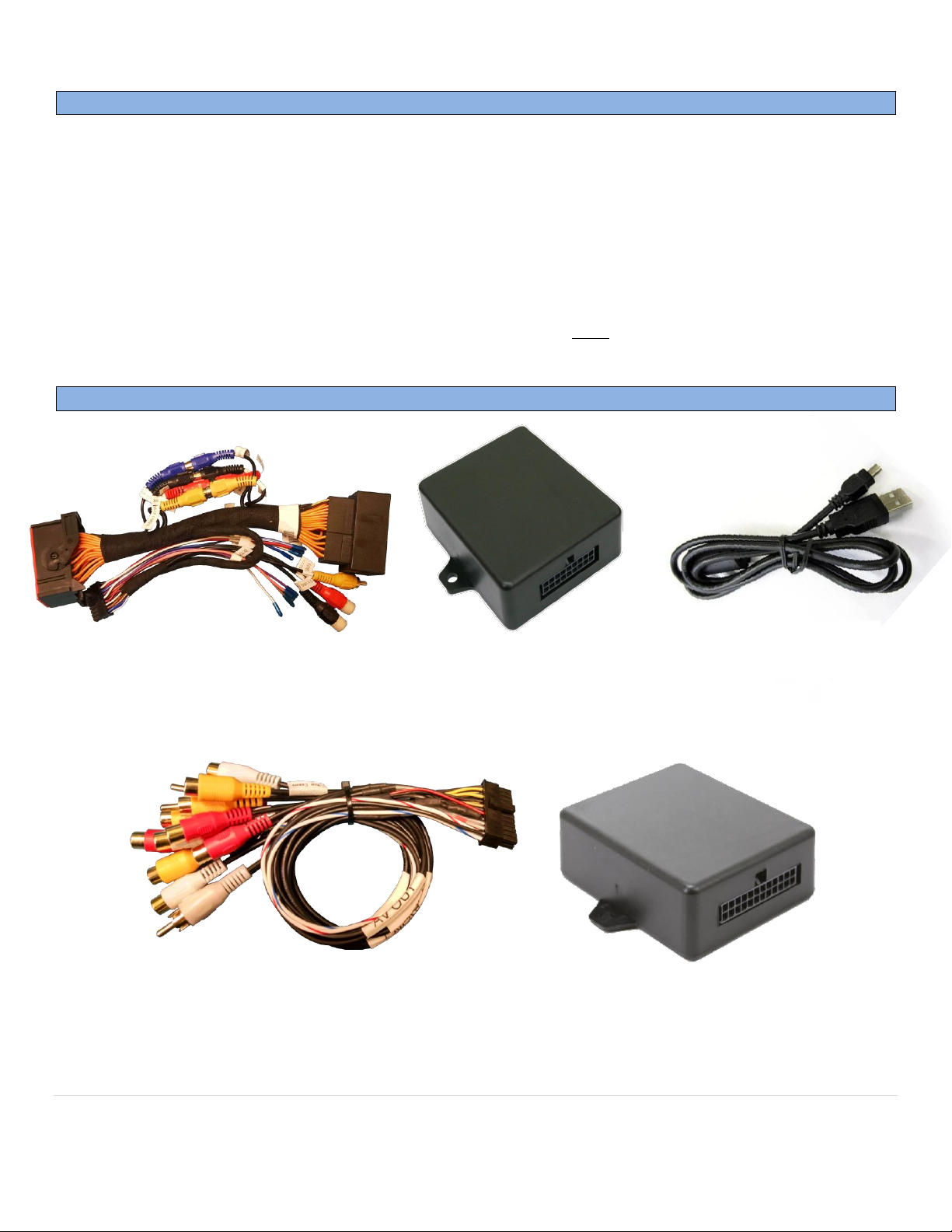
Kit Content
Plug & Play T-harness
NTV-HAR246/264
RA-Connect Module (KT2)
NTV-ASY245
USB Cable (updates)
NTV-CAB009
AVSWv2 module
NTV-ASY255
Power/Trigger Harness
NTV-HAR293
BHM
07/23/18
NTV-DOC265
Agreement: End user agrees to use this product in compliance with all State and Federal laws. NAV-TV Corp. would not be held liable for misuse of its product.
If you do not agree, please discontinue use immediately and return product to place of purchase. This product is intended for off-road use and passenger
entertainment only.
3 | P a g e
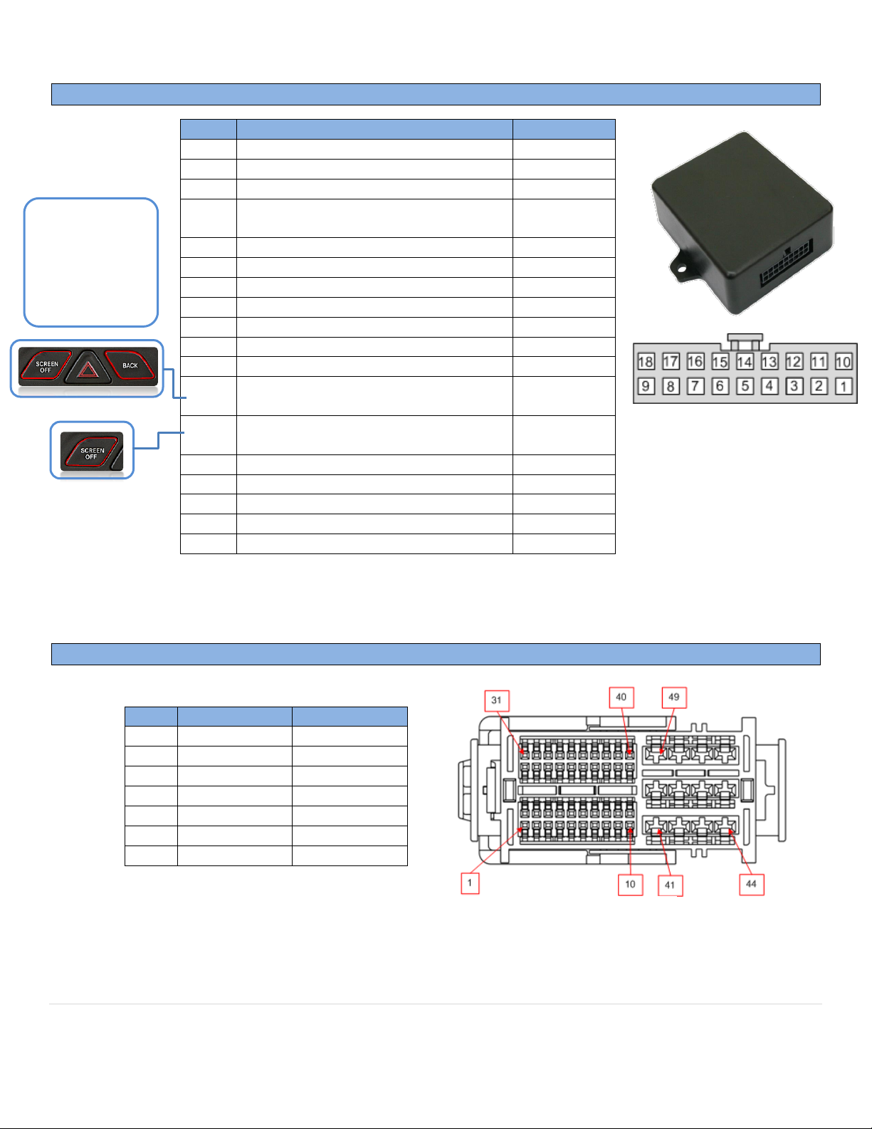
UCTv2 + pin out
RA3/RA4 Radio LCD connector pin out
PIN #
Description
Color 1 12v (+) Constant
Yellow 2 INPUT 1: VIM Activation*
Red
3
--NOT USED--
Blue
4
INPUT 3: Front CAM/Cargo Cam
(selectable)
Pink
5
RX (not present)
--
6
RCA MALE
--
7
RCA Shield
-- 8 CAN HI (Radio Side)
Brown/White 9 CAN HI (Car Side)
Blue/White
10
Ground (-)
Black
11
OUTPUT 1 Provides 12v (+) ACC OUT
White/Red
12
OUTPUT (2) when AUX is activated
(AVSW V1 Trigger)
Blue/White
13
OUTPUT (3) when Front CAM is
activated (AVSW V2 Trigger)
Purple
14
TX INPUT (UART control to SVS-6 RX)
White/Brown
15
RCA Female (Normally Open)
--
16
RCA Female (Normally Closed)
--
17
CAN LO (Radio Side)
Brown
18
CAN LO (Car Side)
Blue
Pin #
Description
Color
2
CAN HIGH
Dark Blue
12
CAN LOW
White
31
Diff Video (-)
Green/Brown
32
Diff Video (+)
Green/Orange
33
Shield
43
Ground
Black
44
Constant 12v
Red
OUTPUTs 2 & 3
send 12v (+) with
corresponding
button press
(force cam)
Wire Side
PIN Side
*Not supported on all models
BHM
07/23/18
NTV-DOC265
Agreement: End user agrees to use this product in compliance with all State and Federal laws. NAV-TV Corp. would not be held liable for misuse of its product.
If you do not agree, please discontinue use immediately and return product to place of purchase. This product is intended for off-road use and passenger
entertainment only.
4 | P a g e
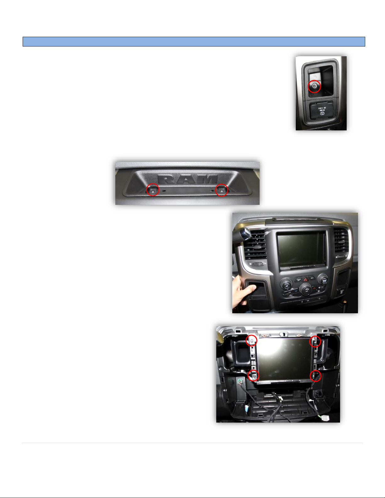
Dash Disassembly (basic RAM)
1. Remove the Torx t20 screw at the right rear of the pocket on the right side of the
dash.
2. Remove (2x) Torx t20 at the top of the dash. They are hidden beneath a rubber mat.
3. The face should be free now, pull straight outwards (towards
you) with medium force. Use plastic panel tools if necessary.
4. Remove (4x) 7mm screws that secure the LCD
touchscreen.
 Loading...