

BHM
01/04/19
NTV-DOC326
1 | P a g e
Agreement: End user agrees to use this product in compliance with all State and Federal laws. NAV-TV Corp. would not be held liable for
misuse of its product. If you do not agree, please discontinue use immediately and return product to place of purchase. This product is
intended for off-road use and passenger entertainment only.
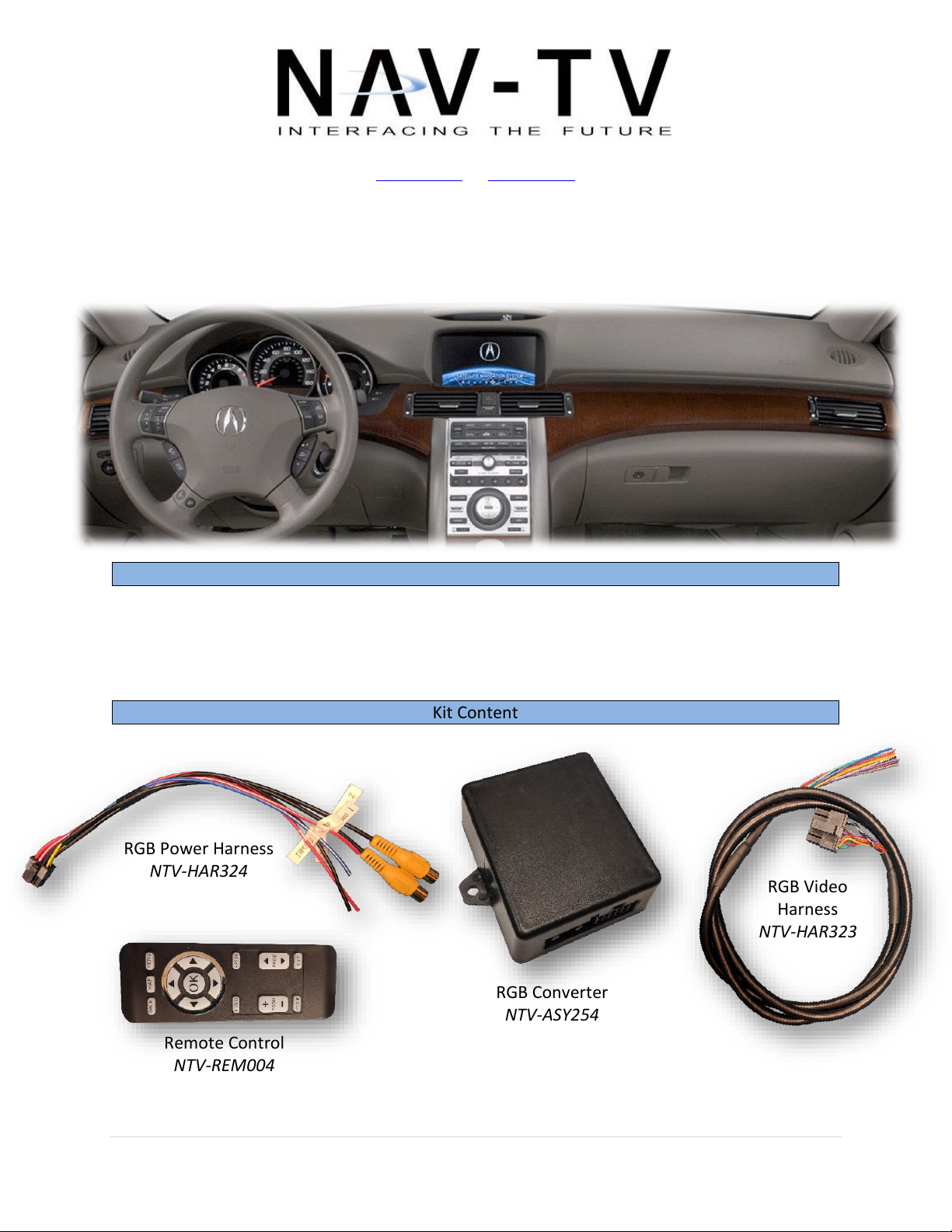
RGB Power Harness
NTV-HAR324
Remote Control
NTV-REM004
3950 NW 120th Ave, Coral Springs, FL 33065 TEL 561-955-9770 FAX 561-955-9760
www.nav-tv.com info@nav-tv.com
RGBv2
NTV-KIT885
Overview
The RGBv2 adds an aftermarket backup camera to the factory navigation screen in select RGBbased navigation-equipped vehicles. A secondary video input is included on the RGB module
and can be viewed at any time by supplying power to an input wire (optional).
Kit Content
RGB Video
Harness
NTV-HAR323
RGB Converter
NTV-ASY254
BHM
01/04/19
NTV-DOC326
2 | P a g e
Agreement: End user agrees to use this product in compliance with all State and Federal laws. NAV-TV Corp. would not be held liable for
misuse of its product. If you do not agree, please discontinue use immediately and return product to place of purchase. This product is
intended for off-road use and passenger entertainment only.
Power Harness
RGB Video Harness
Wire Side
Wire Side
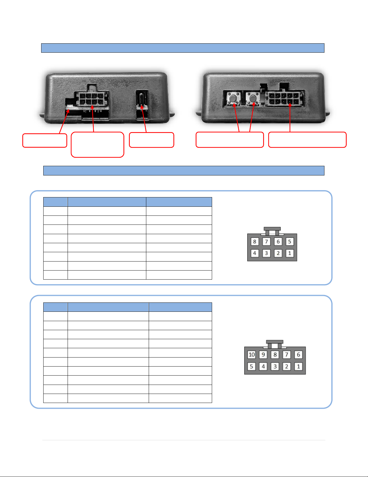
RGBv2 Interface Connectors
RGBv2 Pin Out
PIN #
Description
Color
1
Ground (-)
Black
2
INPUT 2 (AUX VIDEO)
White/Blue
3
Shield (VIDEO 2)
Black
4
Signal (VIDEO 2)
Yellow
5
12v (+) ACC IN
Red
6
INTPUT 1 (CAM VIDEO)
White/Red
7
Shield (VIDEO 1)
Black
8
Signal (VIDEO 1)
Yellow
PIN #
Description
Color
1
RGB Ground
White
2
SYNC (screen)
Gray
3
Blue Signal (screen)
Blue
4
Red Signal (screen)
Red
5
Green Signal (screen)
Green
6
RGB Ground
N/A
7
SYNC (radio/NAV)
Brown
8
Blue Signal (radio/NAV)
Purple
9
Red Signal (radio/NAV)
Orange
10
Green Signal (radio/NAV)
Yellow
IR Receiver
RGBS wires IN & OUT
Power, Video
IN & triggers
LED status
Brightness buttons

BHM
01/04/19
NTV-DOC326
3 | P a g e
Agreement: End user agrees to use this product in compliance with all State and Federal laws. NAV-TV Corp. would not be held liable for
misuse of its product. If you do not agree, please discontinue use immediately and return product to place of purchase. This product is
intended for off-road use and passenger entertainment only.
Universal RGBv2 Installation
1. If this vehicle has a navigation unit separate from the radio, connect this interface
there. If this vehicle has no navigation unit (or NAV is built-in to the radio), connect
this interface at the screen.
2. Gain access behind the screen/navigation unit and disconnect all
connected harnesses before cutting any wires.
3. Examine the wires available from the provided RGB Video Harness.
These wires are used for separating the red, green, blue and SYNC signals
(like you would with a relay).
4. Find the RGBS wires connecting the NAV drive (or radio stack) to the screen. Make sure
you have the correct harness by disconnecting the plug while the radio is in the
NAVIGATION mode: the image should disappear immediately. The RGBS wires will
typically be surrounded by sheathing to block interference.
5. Cut the Red, Green, Blue and Sync SIGNAL wires in half, one at a time. The colors of
these wires are rarely red for red, green for green etc. The best way to do this:
a. Strip sheathing back and gain access to the wires (gain extra slack)
b. Make sure nothing is shorted
c. Turn the car on and put the radio in NAV mode (if available)
d. Cut each wire you suspect to be Red sig, Green sig, Blue sig and SYNC sig one at a
time, and with each cut you should lose the corresponding signal color on the
NAV screen.
e. Cut the SYNC wire. This will make the image stutter and/or scroll lines either
horizontally or vertically.
f. Do not cut the RGB ground in half. Connect the ground wires together from the
RGB Video harness and splice into the RGB ground. See diagram on next page.
6. Connect each wire from the RGB Video Harness to the NAV/Radio side and Screen side
of each signal (red, green, blue, SYNC). Connect the RGB ground wires together and
splice them to the RGB ground (sometimes the sheathing itself). See (universal) diagram
for visual aid.
7. Proceed to page 4 to complete wiring to the Power Connection Harness.
 Loading...