

BHM
Overview
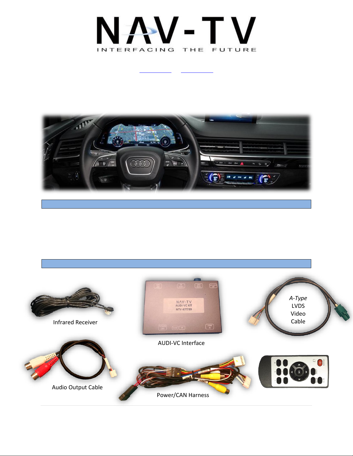
Kit Contents
Infrared Receiver
OSD Menu Remote
Power/CAN Harness
A-Type
LVDS
Video
Cable
AUDI-VC Interface
Audio Output Cable
12/12/16
NTV-DOC276
3950 NW 120th Ave, Coral Springs, FL 33065 TEL 561-955-9770 FAX 561-955-9760
www.nav-tv.com info@nav-tv.com
AUDI-VC
NTV-KIT789
The AUDI-VC Kit interfaces a backup camera input (with active parking lines), 1 additional
composite video input and an HDMI source into the Virtual Cockpit cluster screen equipped in
select 2017 Audi A4, Q7, TT or R8 vehicles. Installation is performed behind the radio (inside
glove box).
Agreement: End user agrees to use this product in compliance with all State and Federal laws. NAV-TV Corp. would not be held liable for
misuse of its product. If you do not agree, please discontinue use immediately and return product to place of purchase. This product is
intended for off-road use and passenger entertainment only.
1 | P a g e
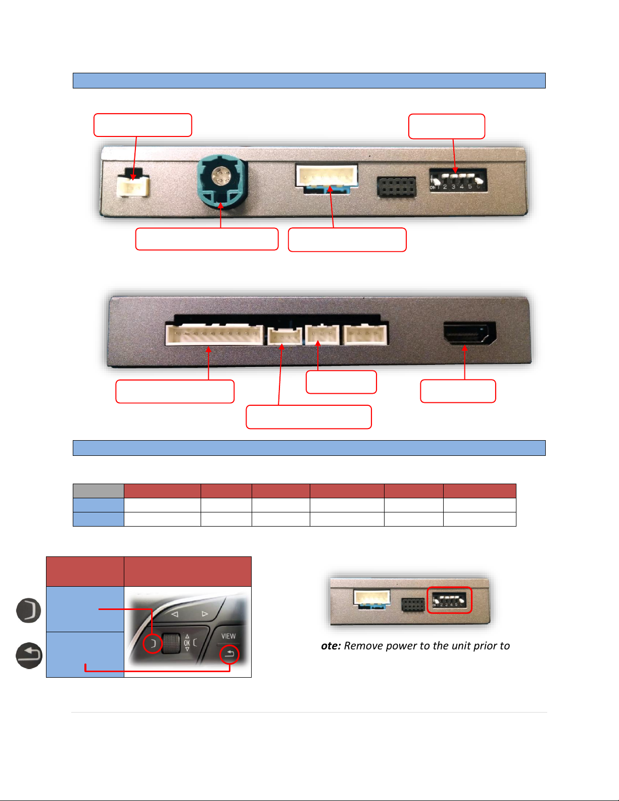
Interface Connectors
Dip Switch Settings
Dip SW:
1 2 3
4 (trans)
5 6 UP
No HDMI
A4 / Q7
See below
AUTOMATIC
Leave UP
Leave Down
DOWN
Adding HDMI
TT
See below
MANUAL
Leave UP
Leave Down
Dip Switch 3
HDMI Activation choice
(steering wheel)
UP
DOWN
Power/CAN Harness
Video Trigger (optional)
Dip Switches
Note: Remove power to the unit prior to
making adjustments to the dip switches
Video OUT (to cluster LCD)
HDMI Audio OUT
HDMI Input
IR Receiver
Video IN (from radio)
BHM
12/12/16
NTV-DOC276
Agreement: End user agrees to use this product in compliance with all State and Federal laws. NAV-TV Corp. would not be held liable for
misuse of its product. If you do not agree, please discontinue use immediately and return product to place of purchase. This product is
intended for off-road use and passenger entertainment only.
2 | P a g e
12/12/16
AUDI-VC Installation
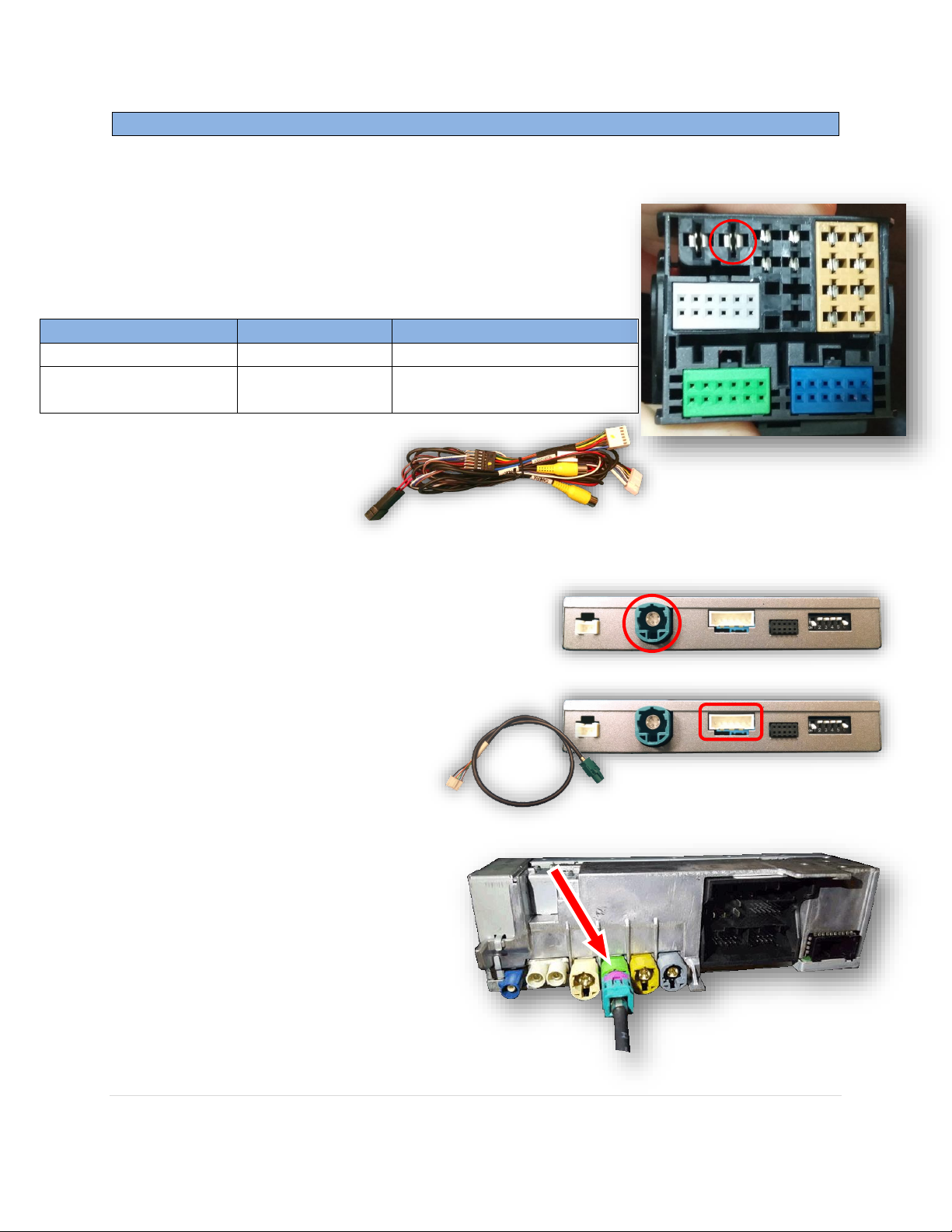
Interface wires
Connect to car
Location
Black (Ground)
Chassis Ground
PIN 15 (Radio plug)
Red (ACC 12v)
ACC 12v (+)
Black/White or Black/Blue @
pass fuse box
NTV-DOC276
1. Remove the MIB radio module located in glove box – this will require an 8mm socket and
possibly a right-angle driver. Disconnect any associated
harnesses and set the radio aside.
2. Grab the provided ‘Power/CAN Harness’ from the
AUDI-VC kit. Connect the following wires to the car:
3. Locate the factory Pink (For AUDI’s with NAV, this connector is GRAY), 4-pin round
connector that was removed from the radio in
step 1. Connect this factory plug to the AUDI-VC
interface at the port labeled ‘LVDS OUT’.*
4. Connect the smaller white plug side of the
provided LVDS Video Cable to the
port on the AUDI-VC interface
labeled ‘LVDS IN’.
5. Connect the free end of the
provided LVDS Video Cable (green)
back to the factory radio at the
bright GREEN cluster LCD port.
BHM
Agreement: End user agrees to use this product in compliance with all State and Federal laws. NAV-TV Corp. would not be held liable for
misuse of its product. If you do not agree, please discontinue use immediately and return product to place of purchase. This product is
intended for off-road use and passenger entertainment only.
3 | P a g e

Remove gray OEM 12-pin
Connect the female 12-pin side of the plug
& play portion to the OEM main MIB
connector as shown. Note the paint dot
must face towards the thick power wires.
If the connector does not secure properly,
zip tie the harness in place to surrounding
wires leaving slack so that the connector
stays in place. Use a spot of glue on the
back side if you’re still concerned with
this.
Note: sometimes it is easier to connect the
main plug back to the MIB module first
and then connect this 12-pin in.
Connect OEM 12-pin to provided 12-pin
(black, PIN-side). NOTE: printed arrow
location on provided 12-pin plug vs OEM plug.
6. Connect the provided 12-pin plug & play portion from the main power harness to the
main factory MIB radio connector as shown below. Pay attention to the orientation, as
this is vital to proper operation:
BHM
12/12/16
NTV-DOC276
7. Connect ground and power for your camera, you may use the provided brown wire
(labeled ‘REAR12VOUT’) for power for convenience. NOTE: This power source will only
supply 12v when the vehicle is in reverse (if forced rear camera is desired at any time,
you’ll need to use an ACC source for power instead).
Agreement: End user agrees to use this product in compliance with all State and Federal laws. NAV-TV Corp. would not be held liable for
misuse of its product. If you do not agree, please discontinue use immediately and return product to place of purchase. This product is
intended for off-road use and passenger entertainment only.
4 | P a g e

12/12/16
NTV-DOC276
8. Connect the video feed from the camera to the RCA among the main power harness
labeled ‘CAMERA’.
9. Connect the white plug from the Power/CAN Harness to the port on the AUDI-VC
interface labeled ‘POWER CAN’.
10. Connect the HDMI Cable (not provided) from the HDMI
source to the HDMI-IN port on the AUDI-VC.
a. If using HDMI, audio is extracted from the
module via the provided Audio Output Cable
from the port on the interface labeled ‘HDMI
AUDIO OUT’.
11. Optional: If adding an additional composite video input (including front camera), connect
the video signal to the RCA among the Power/CAN Harness labeled ‘CVBSIN’.
12. Start the car and test for proper functionality before replacing any dash pieces.
BHM
Agreement: End user agrees to use this product in compliance with all State and Federal laws. NAV-TV Corp. would not be held liable for
misuse of its product. If you do not agree, please discontinue use immediately and return product to place of purchase. This product is
intended for off-road use and passenger entertainment only.
5 | P a g e

NTV-DOC276
AUDI-VC Operation
With Dip Switch #3 DOWN:
Press & hold BACK ARROW (2 seconds) to cycle
through installed & active video input options. Order:
OEM-AV1-AV2-AV3-HDMI-OEM
With Dip Switch #3 UP:
Press & hold LEFT TAB (2 seconds) to cycle through
installed & active video input options. Order:
OEM-AV1-AV2-AV3-HDMI-OEM
Steering Wheel
HOLD 4 Seconds to change current
screen in AUDI Virtual Cockpit
Cluster from middle to full-size
If a rear camera was installed, placing the vehicle in reverse will show the connected
camera’s image, with dynamic guidelines for convenience.
In order to use HDMI on the cluster, you must begin in Navigation mode on the cluster.
See below for activating HDMI or additional video inputs:
BHM
12/12/16
Additionally, sending 12v (+) to the green wire through a toggle will force the ‘CAMERA’
or ‘CVBSIN’ video signal, selectable via the OSD menu. See page 8 & 9.
*Note: These features will only function when active (see OSD Menu settings & Dip Switch
settings)
Agreement: End user agrees to use this product in compliance with all State and Federal laws. NAV-TV Corp. would not be held liable for
misuse of its product. If you do not agree, please discontinue use immediately and return product to place of purchase. This product is
intended for off-road use and passenger entertainment only.
6 | P a g e

BHM
AUDI-VC Install Diagram
12/12/16
NTV-DOC276
Agreement: End user agrees to use this product in compliance with all State and Federal laws. NAV-TV Corp. would not be held liable for
misuse of its product. If you do not agree, please discontinue use immediately and return product to place of purchase. This product is
intended for off-road use and passenger entertainment only.
7 | P a g e

If adding a front camera OR Aux Video source:
1. Disconnect POWER/CAN Harness from interface
2. Place DIP SWITCH 1 in the DOWN position, reconnect power
3. Press the NAV/MAP button on the MIB controller to activate NAV
Input
4. Press OK button on remote 4 times, then press POWER
SET – FRON CAM must be turned on if adding a front camera and the user
wishes for automatic front camera switching. Options for 5, 7, 9 or 11
seconds are user-selectable for the length of time the front camera input
stays active once the vehicle is placed out of reverse.
If the user wants only an AUX video input without front camera, set AV1-
SEL to ON, leave FRON CAM off.
Once finished with settings, place DIP SWITCH 1 back into the UP position
and reset power to interface.
Menu Adjustments
Functional Parking Guidelines ON/OFF
Parking Distance Control
ON/OFF (while in reverse)
Adjust FPG Position
Adjust PDC Position
‘Safe to move?’ ON/OFF
PDC
Return
(AUX VID
menu
control)
RVC Menu
AUX
VIDEO
Menu
Before you start:
The IR-Eye must be connected
Make sure the car’s ignition is on and radio is on
You must be in Reverse Camera mode OR AUX Video mode (see
below):
Reverse Camera Mode adjusts Reverse Camera Settings
AUX Video Mode adjusts AUX Video Settings
Press the OK BUTTON 4 times (numbers will display per press),
then press POWER.
The OSD Menu will appear on screen (auto-time out in about 5
seconds if no action occurs).
BHM
12/12/16
NTV-DOC276
Agreement: End user agrees to use this product in compliance with all State and Federal laws. NAV-TV Corp. would not be held liable for
misuse of its product. If you do not agree, please discontinue use immediately and return product to place of purchase. This product is
intended for off-road use and passenger entertainment only.
8 | P a g e

NTV-DOC276
AUDI-P60H OSD Menu Options continued
BT-CALL: How a (OEM setup) Bluetooth phone call is handled while in AV/HDMI mode:
o ON - When in AV/NAV mode, the unit will transition to the OEM screen when a
Bluetooth phone call is active, then return when call is ended.
o OFF - There is no screen transition when a BT call is active. The screen will
remain in whatever mode it is currently on.
V-MOVION: N/A
FRON CAM: Front camera timer (AV1) = without expansion board; (AV3) with expansion
board
o 5s, 7s, 9s, 11s: Choose one (timer, in seconds), for the amount of time the front
camera (AV1) shows after the vehicle is transitioned out of reverse gear
o OFF: No timer activation
OEM FCAM: N/A
VIDEO ADJ: Adjust video settings for AV1/HDMI/NAV, etc
BHM
12/12/16
AIR-CON: Used on vehicles that display the HVAC/volume information on the screen
whenever an adjustment is made.
o ON: When in AV/HDMI mode, the screen will transition to the OEM
screen to display the HVAC/volume adjustment, then auto transition back to AV mode.
o OFF: When in AV/HDMI mode, the screen will remain while
HVAC/volume adjustments are made.
REAR MODE: Used to determine operation when the vehicle is placed into reverse.
ON: RVC dip switch (#4) dependent (follows DS #4).
OFF: The unit will ignore the reverse gear/wire. (No screen transition in
AV or OEM)
DIP 4 ON: Aftermarket camera input: In AV/HDMI or OEM, the
screen will transition to the RVC input when reverse is detected.
Will display any extra overlay info, PDC, active guidelines.
DIP 4 OFF: OEM equipped camera: In AV/HDMI the unit will
transition into the OEM screen when reverse is detected.
REVERSE WIRE: Providing 12v (+) to the green wire acts as an external activation for the
selected input (connect through toggle switch, SVS-6, etc).
o REAR MODE: Follows the REAR MODE operation (with guideline overlay and any
additional options)
o REAR: Displays the RVC input video in its raw form (no extra overlays)
o AV1: Displays AV1 input
Agreement: End user agrees to use this product in compliance with all State and Federal laws. NAV-TV Corp. would not be held liable for
misuse of its product. If you do not agree, please discontinue use immediately and return product to place of purchase. This product is
intended for off-road use and passenger entertainment only.
9 | P a g e
 Loading...