

Navionics Geonav 5 Touring User And Installation Manual
User and Installation Guide
5
Touring


READ THIS W ARNING BEFORE USING THE GEONA V
W ARNING
THE ELECTRONIC CHART IS AN AID TO NA VIGA TION DESIGNED TO F ACILIT A TE THE USE OF AUTHORIZED GOVERNMENT CHARTS, NOT TO REPLACE THEM.
ONL Y OFFICIAL GOVERNMENT CHARTS AND NOTICES
TO MARINERS CONT AIN ALL INFORMA TION NEEDED FOR
THE SAFETY OF NAVIGATION AND, AS ALWAYS, THE
CAPT AIN IS RESPONSIBLE FOR THEIR PROPER USE.
The use of the GEONAV implies knowledge and acceptance of this warning by the user .
NOTE: Technical characteristics and functions described in this manual are subject to
change as a result of improvements or changes to the product.
This unit runs Linux, developed under GNU General Public License. Linux is a
registered trademark by Linus Torvalds.

4
English
INTRODUCTION
The GEONAV is a chart plotter that can be interfaced with a
GPS receiver, fishfinder unit, autopilot and other onboard instruments, and allows displaying the boat’s geographical position with respect to an electronic chart. Thanks to the
GEONAV and a NAVIONICS Platinum™ or Gold™ electronic
chart, you will never get lost even in case of fog, bad weather
or dark.
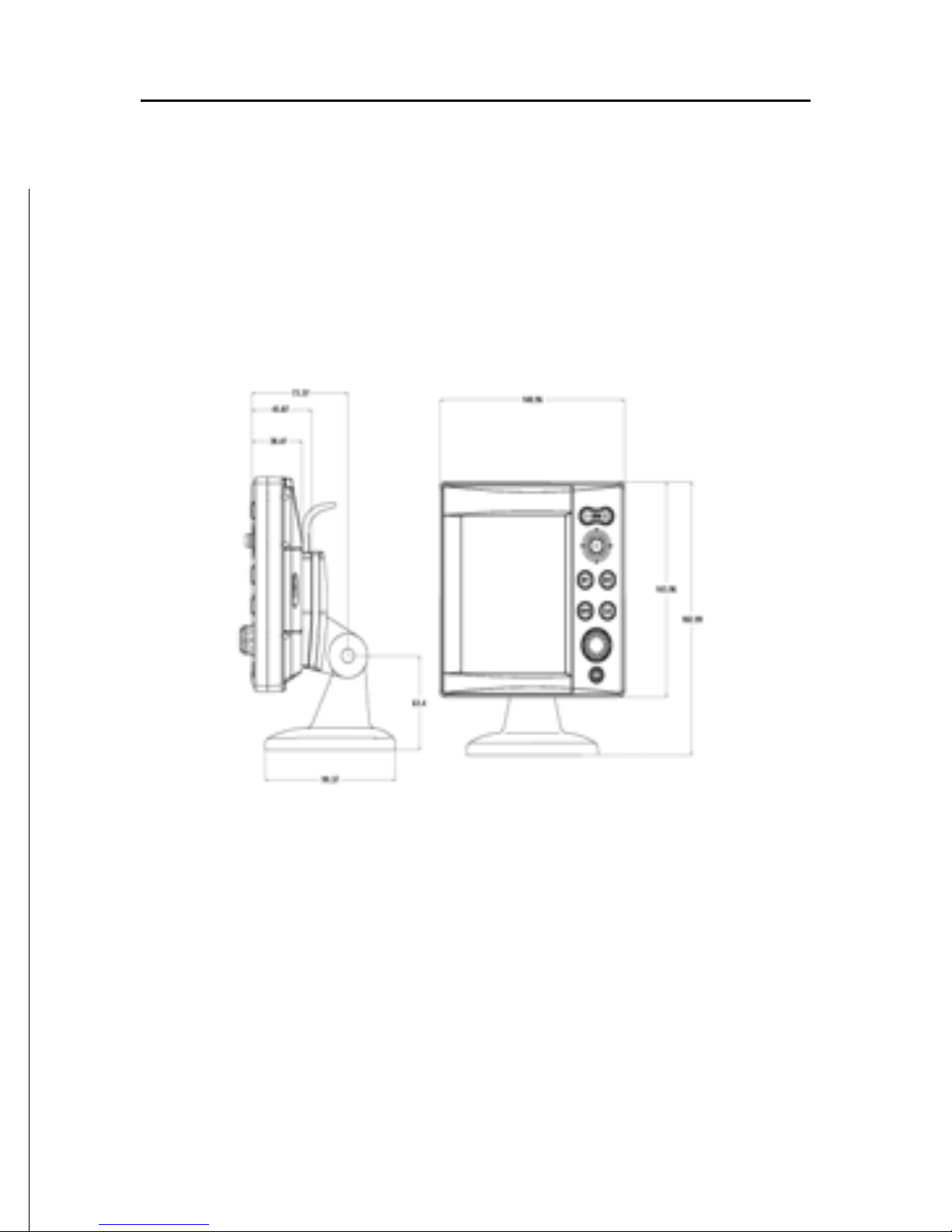
The GEONAV has been designed to allow flush mounting.
Equipped with an easy-to-use keyboard, the GEONAV allows
controlling the autopilot directly from the plotter (Easy Pilot
function) and, thanks to the unlimited capacity of the
CompactFlash™ cartridges - that can also be used on PCs as
personal hard disks - can store a large amount of route, track
and marker data.
The GEONAV is ready for connection with the fishfinder blackbox unit (available as an option) thus becoming a complete
fishfinder instrument, thanks to the dedicated windows automatically enabled when the unit is present.
The Route functions will allow you to plan a trip, while, thanks
to the new multimedia NAVIONICS Platinum™ electronic
charts, you will always know exactly the boat’s position.
NAVIONICS Platinum™ charts provide a detailed coverage of
all the most popular boating areas, offer new functions - such
as 3D display, satellite photographs, etc. - and can be used in
addition to official paper charts to obtain additional information such as the availability of port services, as well as tides
and currents data. NAVIONICS Platinum™ or Gold™ electronic
charts are available worldwide from authorized NAVIONICS
dealers.
When new functions are available, it will be possible to update the GEONAV internal software at any GEONAV dealer.
Introduction

5
English
CHARACTERISTICS
General characteristics
• Easy Pilot function for easy and direct control of autopilot
• EBL and VRM functions
• Multiple display of tracks
• Storage of track data including significant additional information such as date, time, latitude/longitude, depth,
temperature, etc.
• GOTO function (Waypoint, Port, Nearest Service, Marker,
Track, Lat/Lon, R/B)
• Screen Amplifier™ function
• Autozoom™ function
• Overzoom™ function
• 8 marker shapes, 8-character name
• Reverse route function
• Selectable depth units (meters, feet and fathoms)
• Platinum™ electronic charts
• EasyView™ function
• X-Plain™ function
• Heading vector
• CompactFlash™ cartridge
• Storage of routes, tracks and markers in separate files on
CompactFlash™ cartridges
• NMEA 0183 interface
• Interface with fishfinder unit
• Display of depth and water temperature data (if interfaced
with an echosounder)
• Backlit keypad
• Color LCD, transflective TFT 5”, sunlight visible
• Resolution: 240x320 pixels
• Water resistant (IPX6)
• Weight: 491 g
Electrical characteristics
• Power supply: 8 to 18 Vd.c.
• Power consumption: Max. 11 W
Characteristics

6
English
• Protection against: Reverse polarity
Input overvoltage (up to 40 Vd.c.)
• Operating temperature: -10°C to +60°C, with external power
supply (12 V d.c.)
• Storage temperature: -20°C to +70°C, with external power
supply (12 V d.c.)
Memory characteristics
• Up to 100 waypoints per route
• Up to 5000 trackpoints (multiple tracks)
• Up to 3000 markers per group
• Number of routes, tracks and markers: unlimited, depending on the size of the CompactFlash™ utilised
Interface characteristics
• Standard NMEA 0183 sentences
- from position sensor:
GLL, VTG, GGA, RMC, GSV, ZDA, RMA, GSA, GNS,
DTM
- from depth sounder:
DBT, MTW
- to autopilot:
APA, APB, XTE, RMB, BWC, GLL, VTG
If received from the GPS, the following sentences are transmitted: GGA, RMC, ZDA.
Characteristics of the fishfinder unit (optional)
• Rated transmission frequency: 170 kHz
• Max rated power: 350 W RMS
• Beam opening angle: 11° (transducer type A), 13° (transducer type C)
• Standard depth range: 0.8 to 312.5 m (2.5 to 1000 feet)
• Operating temperature: 0°C to +50°C
• Storage temperature: -20°C to +70°C
• Power supply: 10 to 16 V d.c.
• Average power consumption: 7.5 W
Characteristics
7
English
Accessories
• Bracket for detachable installation
• Power supply cable
• User and Installation Guide
• Protection cap
8
English
INSTALLATION AND PRECAUTIONS
Precautions
To avoid electromagnetic interference, the GEONAV must be
positioned at least 25 cm away from the magnetic compass.
Wherever possible, the power supply cable shield should be
connected to the boat’s ground plate.
The GEONAV is water resistant but not waterproof, and should
not be immersed totally in water.
The cartridge slot cover, located on the plotter’s right-hand
side, should always be kept closed and opened only when
replacing cartridges. Make sure that the cartridge replacement
is carried out as the unit is perfectly dry and that no water
enters the unit.
Rear connectors, when not in use, should always be protected
by the appropriate rubber covers.
Cleaning
It is recommended the use of a non-alcoholic
product to clean the glass, since alcoholic
products may damage the glass surface or
make it opaque.
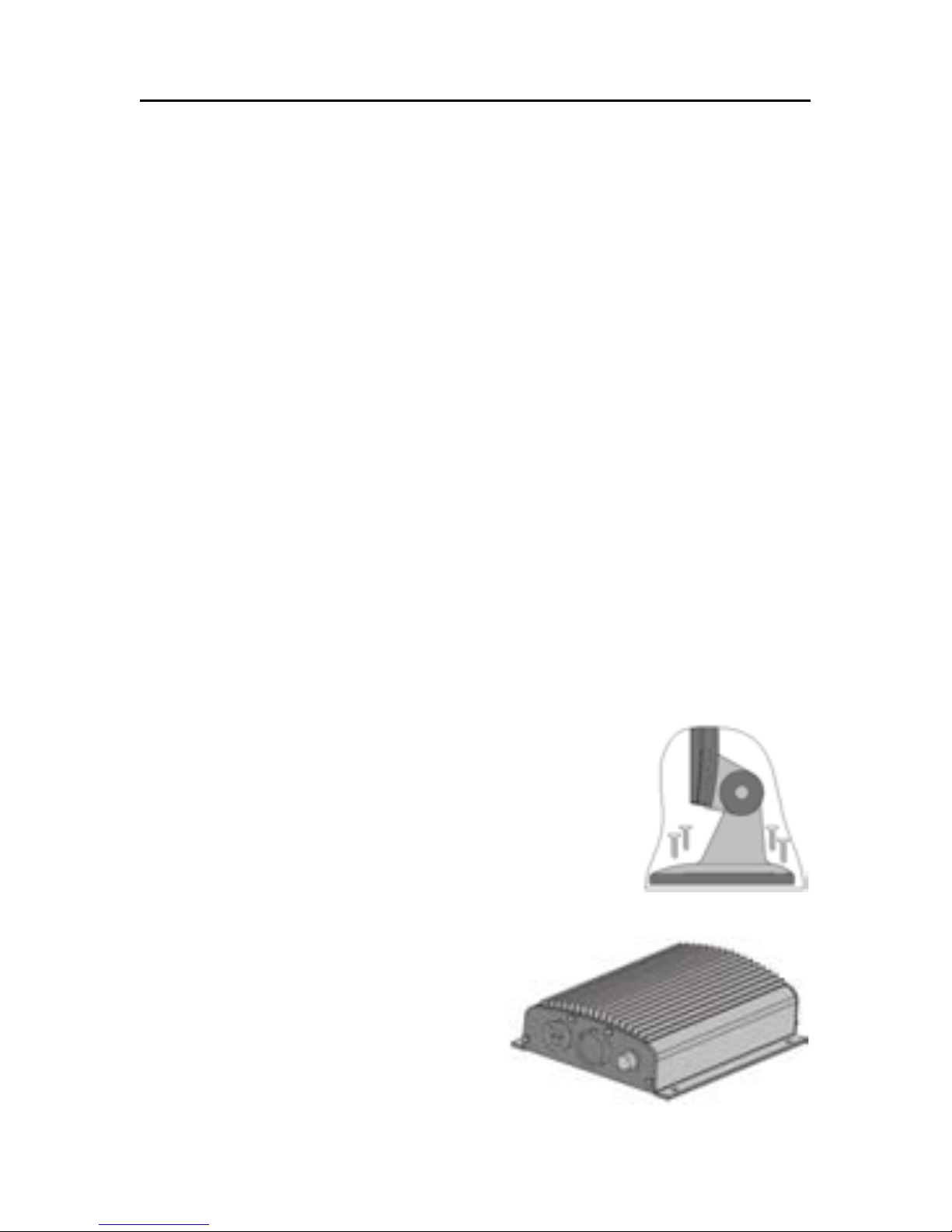
Bracket mounting
Fix the bracket to the boat’s dashboard with 4
screws 5mm in diameter.
Mounting the fishfinder black-box unit
Put the unit in a well-ventilated,
cool and dry place. In case of wall
mounting, turn the unit so that
the connectors are shown on the
unit’s side. This allows avoiding
water infiltration.
Installation and Precautions
9
English
Fix the unit to the wall with 4 screws 3mm in diameter.
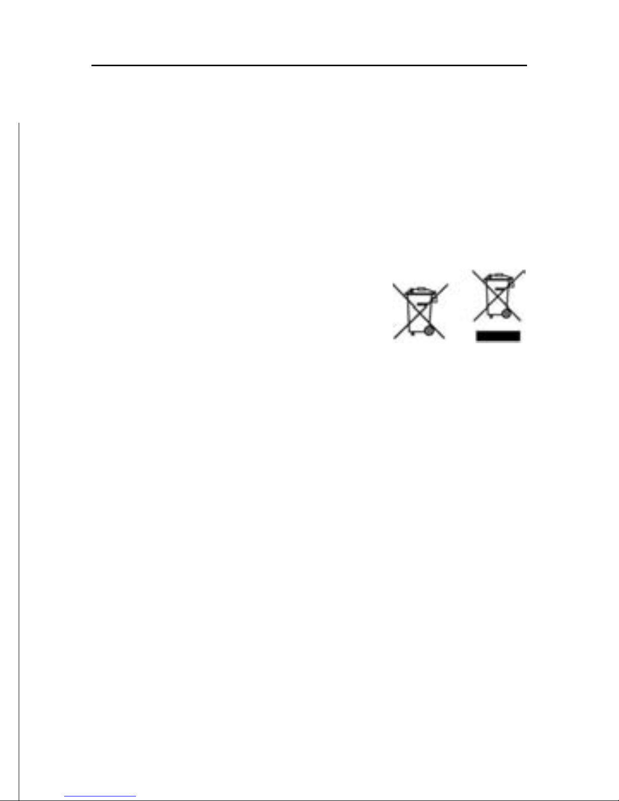
Returning used electrical and electronic devices in EU countries
Users of electrical and electronic devices are obligated to collect used devices
separately. Electrical (electronic) used devices may not be disposed of together with
unsorted household refuse. The separate collection is a condition for reuse, recycling
and utilisation of used electrical (electronic) devices, which ensures the protection of
resources. Electrical (electronic) used devices from private household can be returned free of charge. To return your used device, please
use the country-specific return and collection systems
available to you. Electrical (electronic) devices which
are marked with one of the symbols shown may not be
disposed of with household refuse in accordance with the
EU directive.
10
English
CONNECTIONS
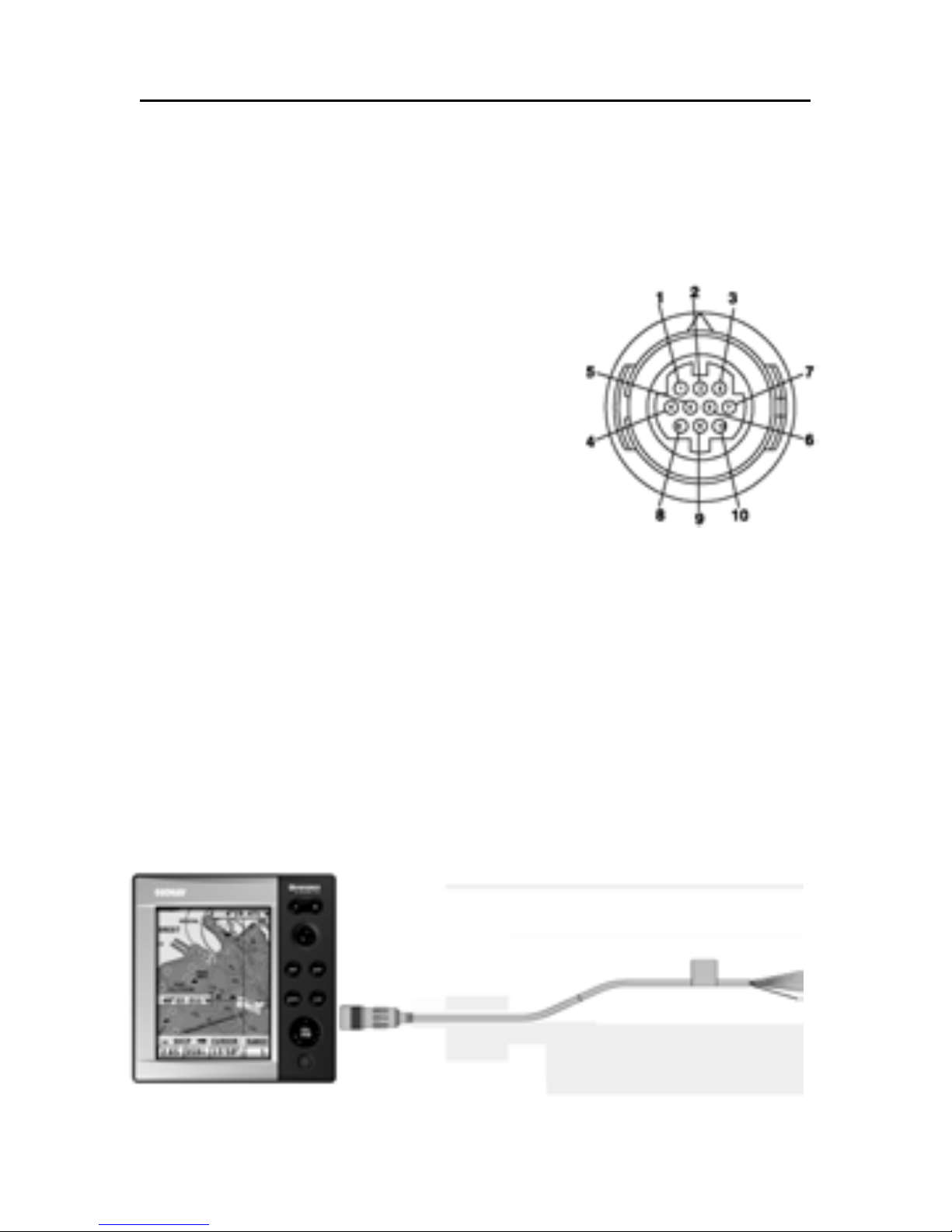
Power supply and data connector (10 pins)
1. Power supply
1 + VDC (red wire)
2 GND (black wire)
2. NMEA 0183 data input
3 GPS IN+ (brown wire)
4 GPS IN- (yellow wire)
3. NMEA 0183 data output
5 DATA OUT+ (violet wire)
6 DATA OUT- (white wire)
4. Connection to the fishfinder black-box unit
7 RESERVED
8 RESERVED
9 RESERVED
10 RESERVED
Connection without fishfinder black-box unit
Use the cable supplied to connect the plotter to the power
supply source, as well as to NMEA0183 devices such as an
external GPS receiver, depth sounder and autopilot, if any.
Connections
PLOTTER POWER SUPPLY
GPS/AUTOPILOT DATA
11
English
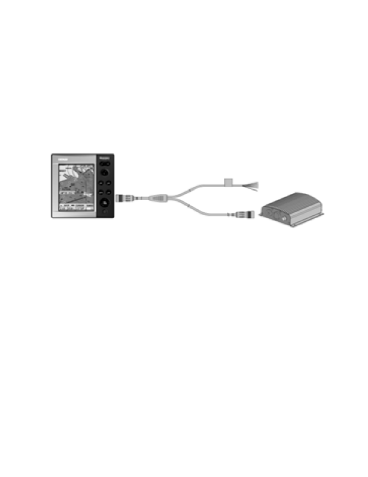
Connection with fishfinder black-box unit
Use the cable supplied to connect the plotter to the power
supply source, as well as to NMEA0183 devices such as an
external GPS receiver, depth sounder and autopilot, if any.
Connect the instrument to the black-box by the available connector present in the cable supplied.
Connect the black-box unit to the power supply source by means
of the power supply cable provided together with the blackbox unit.
NOTE: The black-box unit is NOT powered by the plotter’s connection cable. It is
recommended to make use of the specific power supply cable.
For further information, refer to the Installation Guide supplied with the black-box unit.
PLOTTER POWER SUPPLY
GPS/AUTOPILOT DATA
12
English
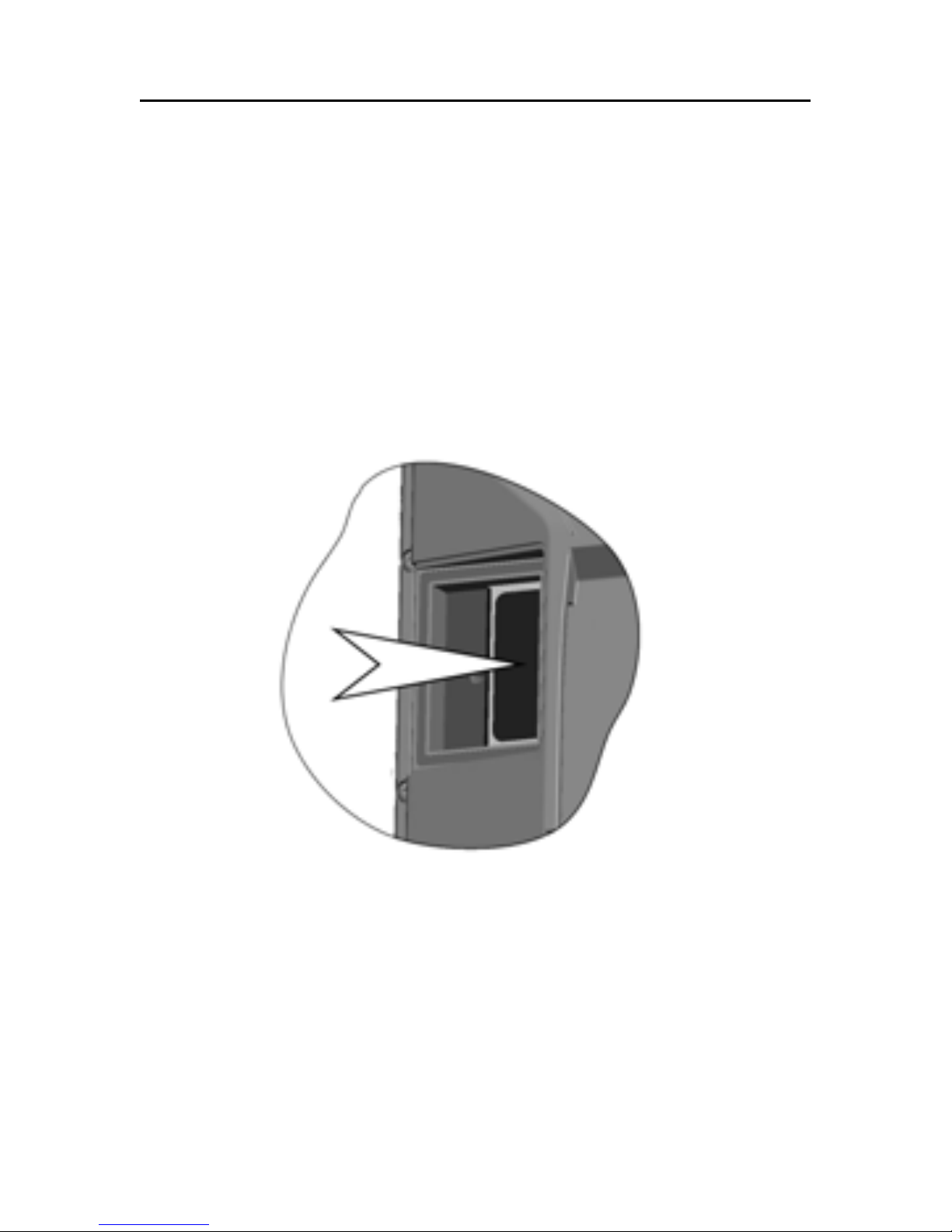
CARTRIDGE INSTALLATION
Installing the CompactFlash™
Open the cartridge slot cover located on the plotter’s rear side.
Insert the cartridge into the appropriate slot, with the label
side towards the outside, and push it down.
Close the cover exercising light pressure and check that it is
perfectly closed, in order to avoid any water infiltration.
NOTE: Ensure that the cartridge is correctly inserted. Attempts to insert the cartridge
upside down with force into the slot may result in damage to the plotter or the
cartridge. This type of damage is not covered by our warranty policy.
Removing the CompactFlash™
Make sure that the plotter is perfectly dry.
Open the cartridge slot cover located on the plotter’s rear side,
then extract the cartridge.
Cartridge Installation

13
English
WARNING: Always use CompactFlash™ cartridges certified by Navionics. The
use of non-certified cartridges may result in improper operation of the unit.
The CompactFlash™ cartridge can be used as a mass storage
device on any PC. The same applies to the GEONAV. However,
the plotter needs to find some free space in the cartridge in
order to work properly. Prior to use a new cartridge, always
make sure that there are at least 2.5MB of free space.
WARNING: Be careful when handling the cartridge files by using the PC. Windows
allows deleting and moving files easily, therefore pay attention when using Windows
Explorer not to erase the content of the \NAVIONIC and \GEONAV folders. Damaging
the files stored in such directories may result in loss of data or improper operation of
the unit.
14
English
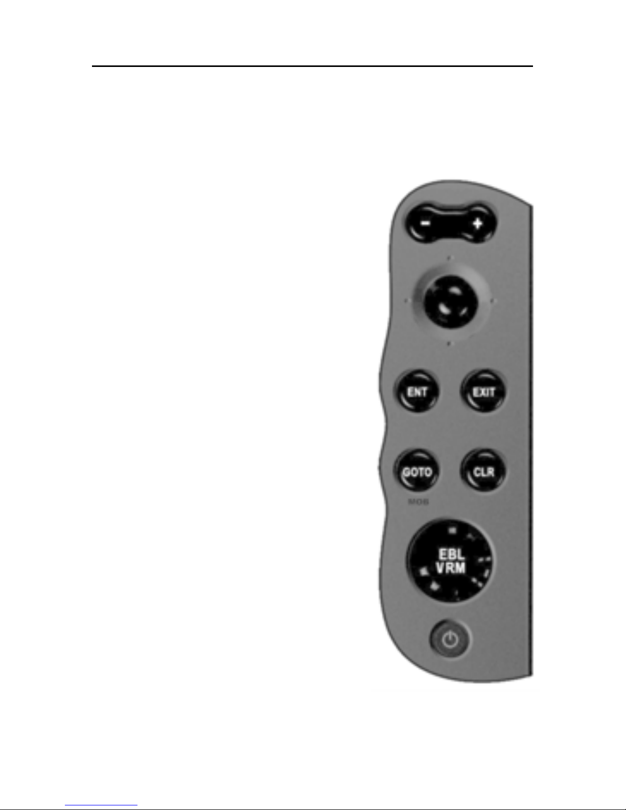
KEYBOARD
ZOOM-/ZOOM+
• Increases/decreases the chart
scale
• Enables/disables the Autozoom
function
JOYSTICK (right/left - up/down)
• Moves the cursor across the screen
• Switches from Navigation mode to
Cursor mode
• Selects the options from menus
and submenus
If pressed:
• Displays the chart object attributes
ENT (ENTER ):
Cursor mode:
• Inserts a waypoint at the cursor’s
position
• Inserts a marker at the cursor’s
position (if held pressed)
Navigation mode:
• Changes the target waypoint
• Inserts a marker at the ship’s position (if held pressed longer)
Menu:
• Confirms a selection
GOTO
• Accesses the main menu and enables the MOB function (if held
pressed longer)
Keyboard

15
English
CLR
• Cancels the setting of data in the windows
• Cancels the option selection from the menu
Cursor mode:
• Deletes all waypoints, starting from the last entered
• Deletes the waypoint pointed by the cursor
• Deletes the marker pointed by the cursor
Navigation mode:
• Deletes the whole current route
KNOB
• Adjusts EBL/VRM parameters
• Selects the several options from the menu windows
• Scrolls letters and numbers when entering data in the
windows
If pressed:
Navigation mode:
• Switches from EBL to VRM
Menu:
• Switches from vertical to horizontal scrolling and confirms
the selection
EXIT
• Cancels a selection
Cursor mode:
• Switches from Cursor mode to Navigation mode
Navigation mode:
• Turns the pages of navigation data
POWER
• Switches the GEONAV on
• Opens the brightness window
• Switches the GEONAV off (if held pressed for more than 3
seconds)

16
English
DIAGNOSTIC
The GEONAV features a diagnostic program to verify its correct performance, once installed, and to detect problems that
may occur during the use of the unit.
To access the diagnostic program, hold the ENTER key pressed
when switching the unit on.
The GEONAV will switch on and carry out automatically a
test of the whole system; as soon as the memory test is completed, the program will allow checking the correct operation
of the unit’s parts.
Press ENTER to run one test or CLR to skip it and pass to the
following test.
WARNING: The unit’s internal memory can be cleared by holding the CLR key
pressed when switching the unit on. This operation will delete all the settings stored
in the GEONAV and restore factory settings. Moreover, the routes, tracks and markers not saved on the CompactFlash™ cartridge will be deleted.
NOTE: In case of damaged cartridge or abnormal power spikes, the unit might lock,
requiring a power shutdown to restart. In that case, the unit can be turned off without
the need of detaching the power, by simply holding the PWR key pressed for more
than 10 seconds. This function is useful if the unit is panel mounted or flush mounted
and the power switch cannot be easily accessed.
Diagnostic
17
English
NAVIONICS ELECTRONIC CHARTS
The GEONAV includes a built-in world map. Additional cartography details relative to a specific area of navigation are
available from the CompactFlash™ cartridges storing
NAVIONICS Platinum™ or Gold™ electronic charts.
NAVIONICS electronic charts contain a detailed set of symbols, similar to those used on official nautical charts.To display chart boundaries, press the
GOTO key to display the menu, select SETUP, SET CHART DETAIL then, by the joystick, select CHART BOUNDARIES ON/
OFF to enable or disable the
boundaries of the charts stored
in the cartridge.
A small square will locate the
area covered by the cartridge installed; position the cursor
within the square and then decrease the chart scale by the
ZOOM+ key to display the details
of the area covered by the cartridge.
The maximum detail level is obtained within port plans where
the smallest point on screen can be equivalent to approximately 1 meter, depending on the cartridge type and coverage.
Increasing/decreasing the chart scale
Press the -ZOOM+ key. The current chart scale is indicated by
a small segment located in the upper left-hand corner or lower
right-hand corner of the screen. Chart scales can range from
4096 NM down to 1/8 NM in Overzoom mode. The scale units
are shown in the range window.
NAVIONICS Electronic Charts
18
English
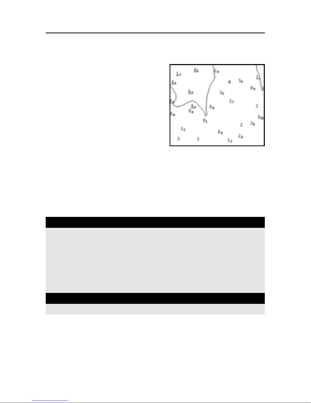
Converting depth values into the units
set
Press GOTO to display the menu,
select SETUP, DEPTH UNITS and
then set the unit desired in
meters, feet or fathoms. The
GEONAV will convert all the
depth values in the unit selected,
making them appear like those reported in the official nautical
charts (see the figure).
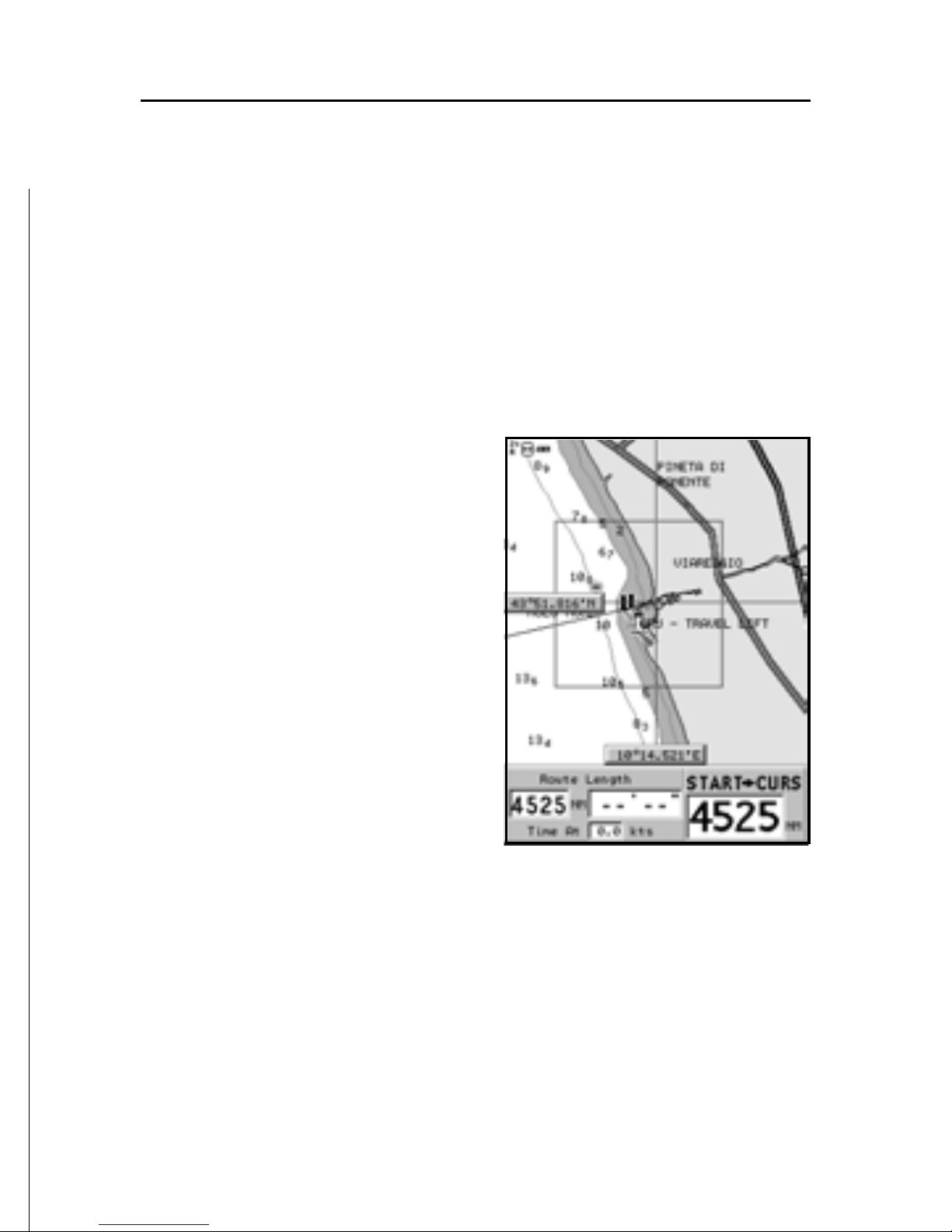
Displaying abbreviated navaid characteristics
Position the manual cursor on the navaid symbol. A window
will show the abbreviated characteristics relative to the navaid
selected.
Description of navaid characteristics:
Displaying object attributes
Move the manual cursor on top of an object on the chart, then
press the joystick. A window will show the description of all
the objects present on the chart at the cursor’s position.
NAVIONICS Electronic Charts
ABBREVIATIONS FOR LIGHT ABBREVIATIONS FOR COLOR
AL alternating AM amber
F fixed B black
FLL fixed and flashing BL blue
FL (...) group flashing G green
FL single flashing OR orange
IQ interrupted quick R red
O C single-occulting VL violet
OC (...) composite group occulting W white
Q continuous group Y yellow
ABBREVIATION FOR PERIOD ABBREVIATION FOR RANGE
xx S xx seconds x xM xx nautical miles
19
English
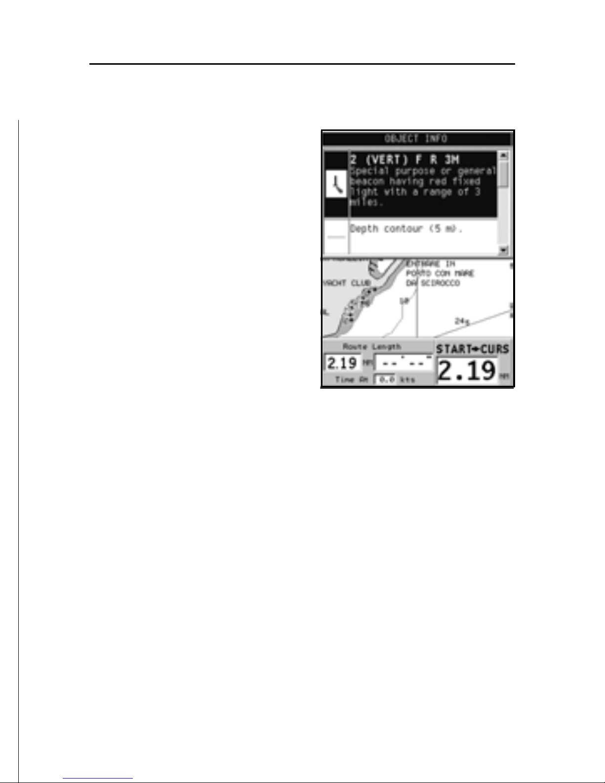
Select one object from this window and press the joystick to
show all of the object attributes.
The objects that can be queried
include depth contours, depth
areas, point objects (lights,
navaids, landmarks, etc.), land
areas, spot soundings, coastlines, rocks, wrecks and, in general, any symbol present on the
chart.
By querying the lights and
navaids, the X-Plain™ function
will give the description of the
object in natural language, thus
avoiding the use of abbreviations
and symbols that are difficult to
understand.
By querying the symbols for wrecks or obstructions,
NAVIONICS Platinum™ or Gold™ charts will provide the most
detailed information available. For example, as far as a boat is
concerned, the chart will show its name, the wreck year, the
hull length, the depth, etc.
Chart presentation mode
The symbols used to represent the objects on the chart (buoys,
lights, landmarks, etc.), as well as chart colors, can be selected between paper-chart International or US styles.
Press GOTO to display the menu, select SETUP, then select
PRESENTATION (INTER. or US).
Depth contours
This function allows the user to select the display of depth
contours; the options available are:
5m: display of contours only with depths up to 5 meters

20
English
NAVIONICS Electronic Charts
10m: display of contours only with depths up to 10 meters
20m: display of contours only with depths up to 20 meters
ALL: all depth contours displayed
Safety contours
This function allows the user to display the depth areas corresponding to the safety contour desired. The options available are:
OFF: no depth area displayed
Other values: the areas with depths up to the value selected
are displayed in shades going from darker blue (for lower depths)
to lighter blue (for higher depths).
The areas whose depths are over the limit set, and therefore
navigable under safety conditions, will be displayed in white.
Dryline areas are always displayed in green.
NOTE: In NIGHT mode, the areas with depths over the limit set, and therefore
navigable under safety conditions, are displayed in black.
Displaying chart details
The display of spot soundings, landmarks and other chart
details can be selectively enabled or disabled from the SETUP,
SET CHART DETAIL menu.
Displaying light sectors
The display of light sectors can be enabled or disabled from
the Setup menu. Press GOTO to display the menu, select SETUP,
SET CHART DETAIL, then LIGHT SECTORS (ON/OFF/AUTO).
Displaying port services
NOTE: This function is available only with the NAVIONICS Platinum™ cartridges
containing the Port Services feature. If the NAVIONICS Gold™ cartridges are used,
the supported functions will be those provided by the chart plotters employing only
the Gold™ charts.
21
English
Position the cursor on the port icon and press ENTER.
A menu will show the options
PORTS, PHOTOS, PILOTS and
INFO. Select PORTS to display
the list of the possible marinas
present in the current port:
choose the desired marina and
press ENTER to display the information available.
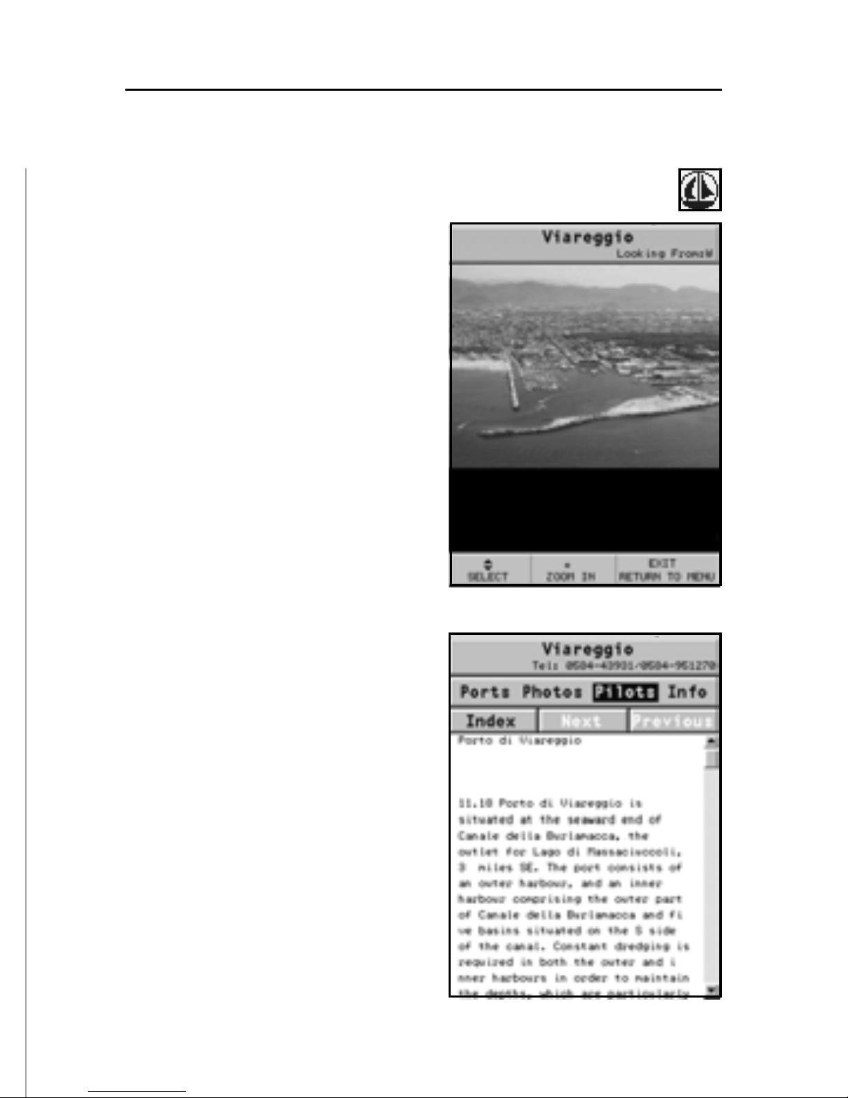
Select PHOTOS, choose one item
from the list to display one of the
photographs available for the
marina, then use the ZOOM key
to enlarge or reduce the image,
and the joystick to pan it.
Select PILOTS to gain access to
the main information on the
marina. To display more detailed
information available, select the
INDEX option from the
submenu.
Select INFO to display the list of
the services available; a window
will show the list of the port services available in the port selected.
Choose the service desired by the
joystick. The number and the
type of icon differ from one port
to another.
22
English
Port services are identified by the following icons:
Once displayed the list of the services available, those shown
in light blue offer further information; select one of them by
the joystick and press ENTER to display the additional data
available, such as the address, telephone number, business
hours, etc. Press ENTER again to carry out a GOTO operation to
the service selected.
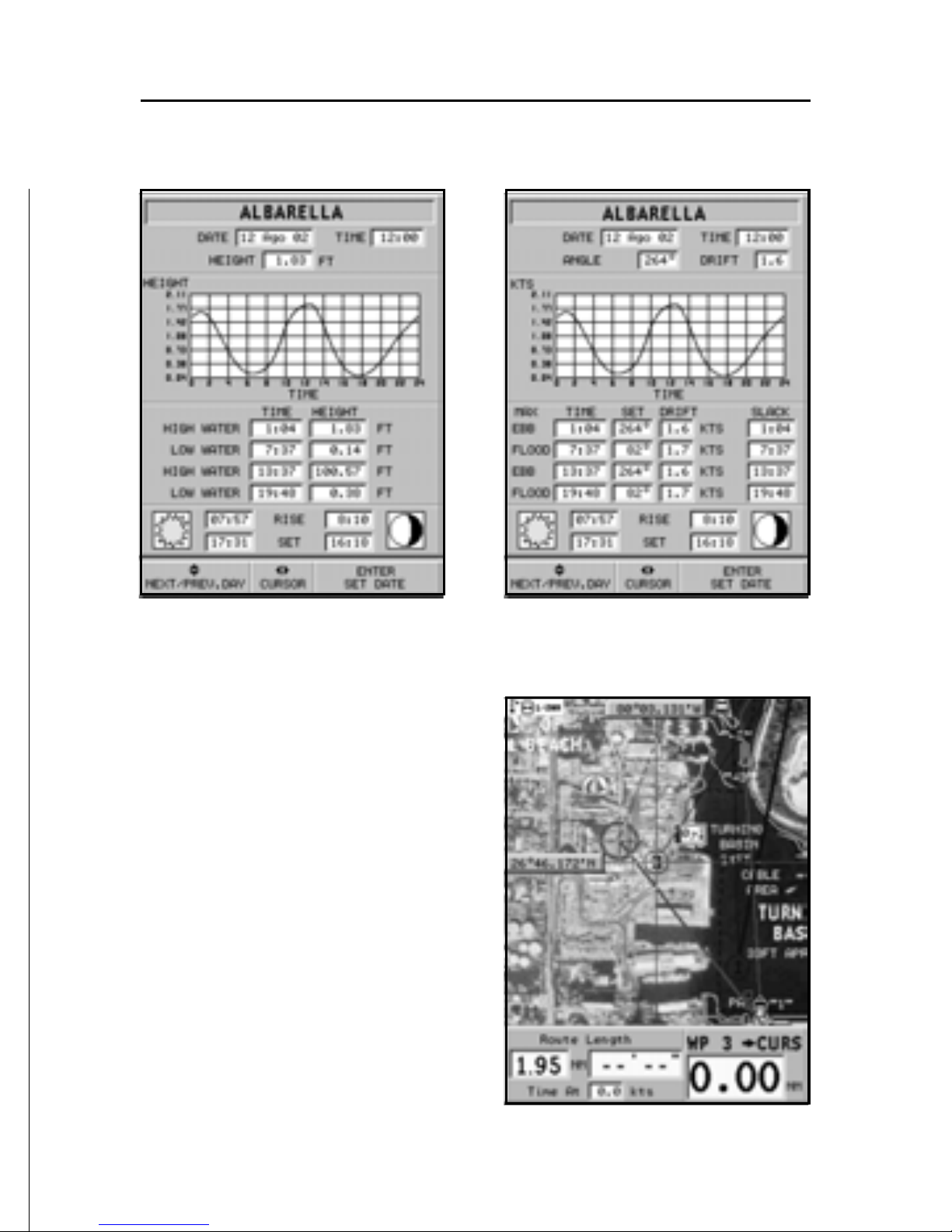
Displaying Tides and Currents data
NOTE: This function is available only with the NAVIONICS cartridges containing
Tides and Currents data.
Position the cursor on the icon representing a
Tide or Current station.
If the zoom level is adequate, the present tide or current
value will show in the vicinity of the cursor position,
together with the curve estimated in the subsequent
hours. Press ENTER to display the whole graph.
The graph will show the tide rate or the tidal stream relevant
to the station selected, as measured during the current day.
NAVIONICS Electronic Charts
Fuel
Customer
services
Repairs
Provisions Information
Info marina
23
English
Displaying aerial / satellite charts
NOTE: This function is available only with
the NAVIONICS Platinum™ cartridges.
Press GOTO to display the menu,
select SETUP, PHOTO OVERLAY, then LAND or FULL.
From a given zoom level onwards, where available, aerial or
satellite photographs will overlay the traditional chart items,
only in land areas (LAND) or both
in land and sea areas (FULL).
24
English
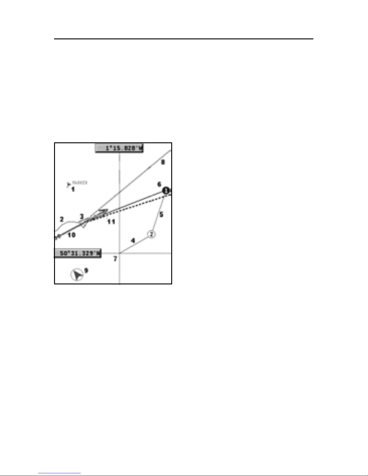
GRAPHIC ITEMS
Besides chart data, the GEONAV displays some graphic items
useful during navigation.
The figure below shows some of these items.
1 - Marker
Indicates a point of interest associated with a symbol, a name
and a color.
2 - Track segment
Recording of the track actually
followed by the boat; the track is
displayed as a colored dashed
line.
3 - Boat’s position
Boat’s position according to the
data received from the GPS receiver.
4 - Rubber band
Line joining the last waypoint entered to the manual cursor,
or the boat’s position to the manual cursor when no waypoint
has been entered.
To delete this band, press the EXIT key and switch to Navigation mode.
5 - Route leg
Part of route between two waypoints.
6 - Waypoint
Waypoints are identified by a circle and a number. The route
starting point is marked by the “X” symbol. The target waypoint
is identified by a filled circle, whereas the route leg currently
followed is identified by a thicker line.
Graphic Items

25
English
7 - Cursor
Indicates the position expressed in geographical coordinates
(latitude and longitude).
It is displayed when the plotter is in Cursor mode.
8 - Heading vector
Indicates graphically the boat’s current route.
9 – North indicator
Indicates the north direction when the Chart rotation function is enabled.
 Loading...