


11C
10C
User and Installation Guide
Manuale d’uso e d’installazione
Manuel d’emploi et d’installation

User and Installation Guide
11C
10C


READ THIS WARNING BEFORE USING THE GEONA V
WARNING
THE ELECTRONIC CHART IS AN AID TO NA VIGA TION DESIGNED TO F ACILIT ATE THE USE OF AUTHORIZED GOV ERNMENT CHARTS, NOT TO REPLACE THEM.
ONLY OFFICIAL GOVERNMENT CHAR TS AND NOTICES
TO MARINERS CONT AIN ALL INFORMATION NEEDED FOR
THE SAFETY OF NAVIGATION AND, AS ALWAYS, THE
CAPTAIN IS RESPONSIBLE FOR THEIR PROPER USE.
The use of the GEONA V implies knowledge and acceptance of this warning by the user.
NOTE: Technical characteristics and functions described in this manual are subject to
change as a result of improvements or changes to the product.
This unit runs Linux, developed under GNU General Public License. Linux is a
registered trademark by Linus Torvalds.

Introduction
INTRODUCTION
The GEONAV is a chart plotter that can be interfaced with a
GPS receiver, autopilot and other onboard instruments, and
allows displaying the boat’s geographical position with respect
to an electronic chart. Thanks to the GEONAV and a
NAVIONICS Gold™ electronic chart, you will never get lost
even in case of fog, bad weather or dark.
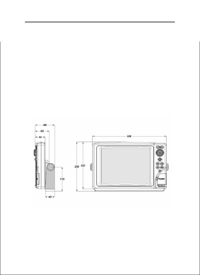
The GEONAV has been designed to allow flush mounting.
Equipped with an easy-to-use keyboard, the GEONAV allows
controlling the autopilot directly from the plotter (Easy Pilot
function) and, thanks to the unlimited capacity of the
CompactFlash™ cartridges - that can also be used on PCs as
personal hard disks - can store a large amount of route, track
and marker data.
The GEONAV is ready for connection with the wind station
and echosounder and, thanks to windows enabled automatically, able to display the relevant data, if available. The connection supports both the NMEA 0183 standard protocol and
the Ethernet Connection system, suitable for the network connection of multiple stations.
The Route functions will allow you to plan a trip, while, thanks
to NAVIONICS Gold™ electronic charts, you will always know
exactly the boat’s position. NAVIONICS Gold™ charts are available for all the most popular boating areas, provide a large
amount of data - thanks to the object-oriented technology and can be used in addition to official paper charts to obtain
additional information such as the availability of port services,
as well as tides and currents data. NAVIONICS Gold™ electronic charts are available worldwide from authorized
NAVIONICS dealers.
4
Should new functions be available in the future, it will be
possible to update the GEONAV internal software at any
NAVIONICS dealer.
English

Characteristics
CHARACTERISTICS
General characteristics
• Easy Pilot function for easy and direct control of autopilot
• Possibility to transfer routes, tracks and markers from one
plotter station to another through network connection
• EBL and VRM functions
• Multiple display of tracks
• Storage of track data including significant additional information such as date, time, latitude/longitude, depth,
temperature, wind data, etc.
• GOTO function (Waypoint, Port, Nearest Service, Marker,
Track, Lat/Lon, R/B)
• Screen Amplifier™ function
• Autozoom™ function
• Overzoom™ function
• 8 marker shapes, 8-character name
• Reverse route function
• Selectable depth units (meters, feet and fathoms)
• Cartography with port services and Tides and Currents
data
• EasyView™ function
• X-plain™ function
• ARPA display function
• Heading vector
• Speed and heading filters
• CompactFlash™ cartridge
• Storage of routes, tracks and markers in separate files on
CompactFlash™ cartridges
• NMEA 0183 interface (ver. 2.03)
• Ethernet connection
• Display of depth and water temperature data (if interfaced
with an echosounder)
• Display of wind data (if interfaced with wind instruments)
• Backlit keypad
• Color LCD, transflective TFT 10.4”, daylight visible (G10C
model)
5
English

Characteristics
• Color LCD, TFT 10.4”, enhanced contrast and brightness,
sunlight visible (G11C model)
Electrical characteristics
• Power supply: 9 to 36 Vd.c.
• Power consumption: Max. 13 W (G10C model)
• Power consumption: Max. 21 W (G11C model)
• Auxiliary voltage output: 10 to 36 Vd.c.
(same as input voltage) - Max. 250 mA
• Protection against: Reverse polarity
Input overvoltage (up to 40 Vd.c.)
Overcurrent at auxiliary voltage output (over 250 mA)
• Operating temperature: 0°C to +55°C
• Storage temperature: -20°C to +70°C
Memory characteristics
• Up to 100 waypoints per route
• Up to 5000 trackpoints (multiple tracks)
• Up to 3000 markers per group
• Number of routes, tracks and markers: unlimited, depending on the size of the CompactFlash™ used
Interface characteristics
• Standard NMEA 0183 sentences
- from position sensor:
GLL, VTG, GGA, RMC, GSV, ZDA, RMA, GSA, GNS,
DTM
- from depth sounder:
DBT, MTW
- from ARPA:
TLL, TTM
- to autopilot:
APA, APB, XTE, RMB, BWC, GLL, VTG
If received from the GPS, the following sentences are transmitted:
GGA, RMC, ZDA.
6
English
Accessories
• Bracket for detachable installation
• Gasket and drilling template for panel mounting
• Plastic frame and drilling template for flush mounting
• Power supply cable
• Auxiliary power supply cable
• User and Installation Guide
• Protection cap
• Carrying case
7
English

Installation and Precautions
INSTALLATION AND PRECAUTIONS
Precautions
Wherever possible, the power supply cable shield should be
connected to the boat’s ground plate.
The GEONAV is water resistant but not waterproof, therefore
it should not be immersed totally in water.
The cartridge slot cover, located on the plotter’s right-hand
side, should always be kept closed and opened only when
replacing cartridges. Make sure that the cartridge replacement
is carried out as the unit is perfectly dry and that no water
enters the unit.
Rear connectors, when not in use, should always be protected
by the appropriate rubber covers.
Cleaning
It is recommended the use of a non-alcoholic product to clean
the glass, since alcoholic products may damage the glass surface or make it opaque.
Panel mounting
Locate the area where the GEONAV is to be installed, then
use the drilling template supplied with the plotter to properly
cut holes and sockets out of the instrument’s panel.
8
The neoprene adhesive gasket supplied must be applied to
the GEONAV rear side to avoid moisture penetration and to
reduce vibrations.
Mounting screws must be 4 mm in diameter and maximum 5
mm in length, plus the thickness of the panel. Do not exceed
tightening the screws, in order to avoid damaging the screw
seats.
English
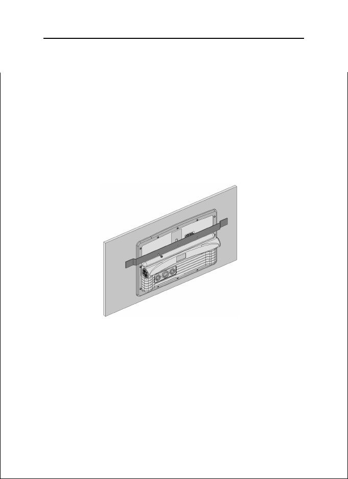
Flush mounting
Locate the area where the GEONAV is to be installed, then
use the cutting template supplied with the plotter to cut the
panel.
Apply a layer of silicone glue (the use of black colored glue is
recommended, in order to prevent the area from going yellow
when exposed to sunlight) to the plastic frame rear part; place
the frame into the socket cut out of the panel, so that the
frame edge leans against the panel.
9
Make sure that the frame and the panel are correctly fixed; if
necessary, apply additional metal brackets (not supplied in
the package) as shown in the relevant figure.
Let the silicone glue dry, then apply the neoprene gasket to
the plotter rear side, insert the instrument into the frame and
lock it by the screws supplied.
Do not exceed tightening the screws, in order to avoid damaging the screw seats.
English
Installation and Precautions
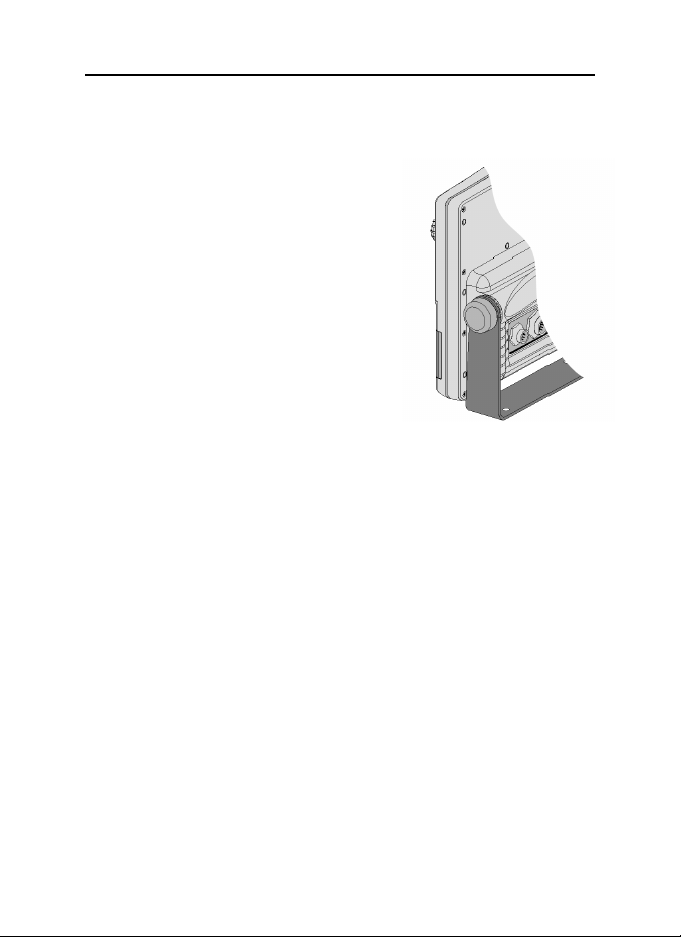
Bracket mounting
Fix the bracket to the boat’s dashboard
by screws 6mm in diameter.
10
English

Connections
11
CONNECTIONS
Power supply and data connector (9 pins)
1. Power supply
1 + VDC
2 GND
2. NMEA 0183 data input
3 GPS IN +
4 GPS IN -
3 . NMEA 0183 data output
5 DATA OUT +
6 DATA OUT -
4. Auxiliary output voltage (Vaux)
7 Vaux+, 250mA *
8 GND
9 SHIELD
* Vaux voltage is the same as the plotter’s input voltage.
If sent by the position sensor, the following NMEA messages
are transmitted to external devices (e.g., autopilot):
APB - XTE - RMB - BWC - GLL - VTG
The GEONAV will add the following messages (if received
from the position sensor):
GGA - RMC - ZDA
Auxiliary connector (7 pins)
Allows connecting the GEONAV to an
auxiliary instrument equipped with
NMEA 0183 interface (e.g., echosounder
and mast head transducer).
1. NMEA 0183 auxiliary data input
1 DATA IN +
2 DATA IN -
English

Connections
Network connector (6 pins)
1. Ethernet connection
1 I AN GND 1
2 RX +
3RX 4 I AN GND 2
5 TX +
6 TX -
12
English
Cartridge Installation
13
CARTRIDGE INSTALLATION
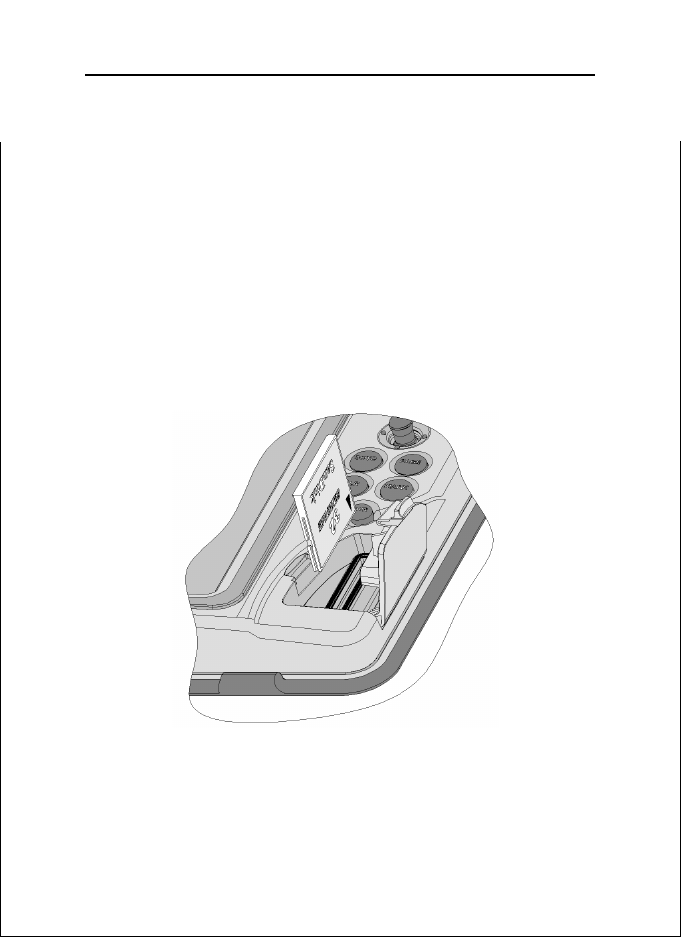
Installing the CompactFlash™
Open the cartridge slot cover located on the plotter’s front
side.
Insert the cartridge into the appropriate slot, with the label
side (side with a small arrow) towards the right, and push it
down.
Close the cover exercising light pressure and check that it is
perfectly closed, in order to avoid any water infiltration.
NOTE: Make sure of inserting the cartridge correctly. Should you try to insert the
wrong side of the cartridge, full insertion into the slot is hampered. Any further attempt
to force the cartridge into the slot may damage the cartridge or the plotter. This kind of
damage is not covered by the warranty.
English

Cartridge Installation
Removing the CompactFlash™
Make sure that the plotter is perfectly dry.
Open the cartridge slot cover located on the plotter’s front
side, then extract the cartridge.
WARNING: Always use CompactFlash™ cartridges certified by Navionics. The
use of non-certified cartridges may result in improper operation of the unit.
The CompactFlash™ cartridges can be used as a mass-storage
with any PC computer, so can be the cartridge used by the
plotter. However, the plotter needs to find some free space in
the cartridge in order to work properly. Prior to use a new
cartridge, always make sure that there are at least 2.5MB of
free space.
WARNING: Be careful when handling the cartridge files by using the PC. Windows
allows deleting and moving files easily, therefore pay attention when using Windows
Explorer not to erase the content of the \NAVIONIC and \GEONAV folders. Damaging
the files stored in such directories may result in loss of data or improper operation of
the unit.
14
English
Keyboard
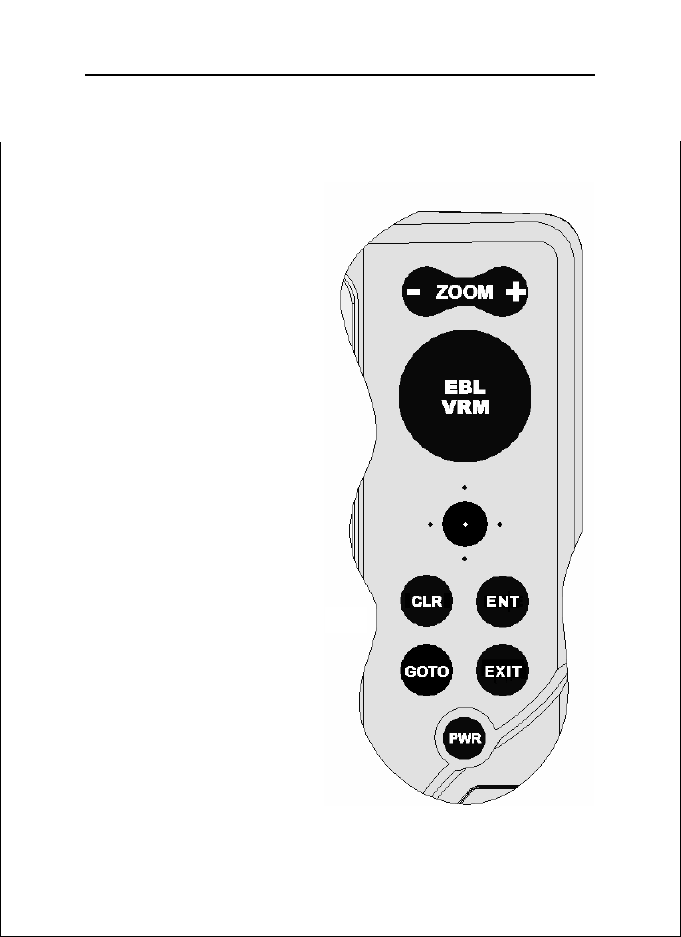
KEYBOARD
ZOOM-/ZOOM+
• Increases/decreases
the chart scale
• Enables/disables the
Autozoom function
JOYSTICK (right/left - up/down)
• Moves the cursor
across the screen
• Switches from Naviga-
tion mode to Cursor
mode
• Selects the options
from menus and
submenus
If pressed:
• Displays the chart ob-
ject attributes
ENT (ENTER):
Cursor mode:
• Inserts a waypoint at
the cursor’s position
• Inserts a marker at the
cursor’s position (if
held pressed)
Navigation mode:
• Changes the target
waypoint
Menu:
• Confirms a selection
15
English

Keyboard
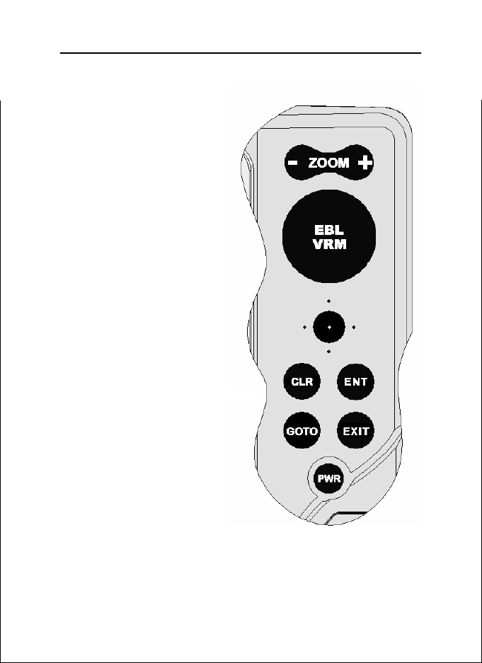
GOTO
• Accesses the main menu
Plots a route to:
• A new target waypoint
• A marker
• A port
• The nearest port service
Positions the cursor on the coordinates selected (Lat/Lon or
Range/Bearing).
CLR
• Cancels the setting of data in the windows
• Cancels the option selection from the menu
Cursor mode:
• Deletes all waypoints, starting from the last entered
• Deletes the waypoint pointed by the cursor
• Deletes the marker pointed by the cursor
Navigation mode:
• Deletes the whole current route
KNOB
• Adjusts EBL/VRM parameters
• Selects the several options from the menu windows
• Scrolls letters and numbers when entering data in the
windows
16
If pressed:
Navigation mode:
• Switches from EBL to VRM
Menu:
• Switches from vertical to horizontal scrolling and confirms
the selection
EXIT
• Cancels a selection
English
Cursor mode:
• Switches from Cursor
mode to Navigation
mode
Navigation mode:
• Turns the pages of
navigation data
PWR
• Switches the GEONAV
on
• Opens the contrast/
brightness window
• Switches the GEONAV
off (if held pressed for
more than 3 seconds)
17
English

Diagnostic
18
DIAGNOSTIC
The GEONAV features a diagnostic program to verify its correct performance, once installed, and to detect problems that
may occur during the use of the unit.
To access the diagnostic program, keep pressed any key but
CLR, while pressing the PWR key.
The GEONAV will switch on and carry out automatically a
test of the whole system; as soon as the memory test is completed, the program will test the LCD, the CompactFlash™
card and the keyboard. Press ENTER to run one test, CLR to skip
to the next one. To exit from the keyboard test, press CLR
twice.
Once the keyboard test is completed, the diagnostic program
allows checking the messages received from the GPS through
the NMEA 0183 port. Hold the knob pressed to freeze the
messages on the screen, then release it to keep on displaying
the new messages sent by the GPS. To test channel 1 (depth
sounder or wind instrument), press GOTO. Press CLR to quit.
After the keyboard, the diagnostic program will test the internal non-volatile memory and the backlight. Press ENTER to run
one test, CLR to skip to the next one.
Once terminated all tests, press ENTER to re-boot the unit.
WARNING: The internal memory can be cleared by pressing simultaneously the
PWR and CLR keys. This operation will delete all the settings stored in the GEONAV
and restore factory settings.
NOTE: In case of damaged cartridge or abnormal power spikes, the unit might lock,
requiring a power shutdown to restart. In that case, the unit can be turned off without
the need of detaching the power, by simply holding the PWR key pressed for more
than 10 seconds. This function is useful if the unit is panel mounted or flush mounted
and the power switch cannot be easily accessed.
English
NAVIONICS Electronic Charts
19
NAVIONICS ELECTRONIC CHARTS
The GEONAV includes a built-in world map. Additional cartography details relative to a specific area of navigation are
available from the CompactFlash™ cartridges storing
NAVIONICS Gold™ electronic charts.
NAVIONICS electronic
charts contain a detailed set
of symbols, similar to those
used on official nautical
charts.
To display chart boundaries, press the GOTO key to
display the menu, select
SETUP/DISPLAY, then
CHART BOUNDARIES and,
by the joystick, select ON/
OFF to enable/disable the
boundaries of the charts
stored in the cartridge.
A small square will locate the area covered by the cartridge
installed; position the cursor within the square and then decrease the chart scale by the ZOOM+ key to display the details
of the area covered by the cartridge.
The maximum detail level is obtained within port plans where
the smallest point on screen can be equivalent to approximately 1 meter, depending on the cartridge type and coverage.
Increasing/decreasing the chart scale
Press the -ZOOM+ key. The current chart scale is shown by a
small segment in the lower right-hand corner of the screen.
Chart scales can range from 512 NM down to 40 ft in Overzoom
mode.
English
NAVIONICS Electronic Charts
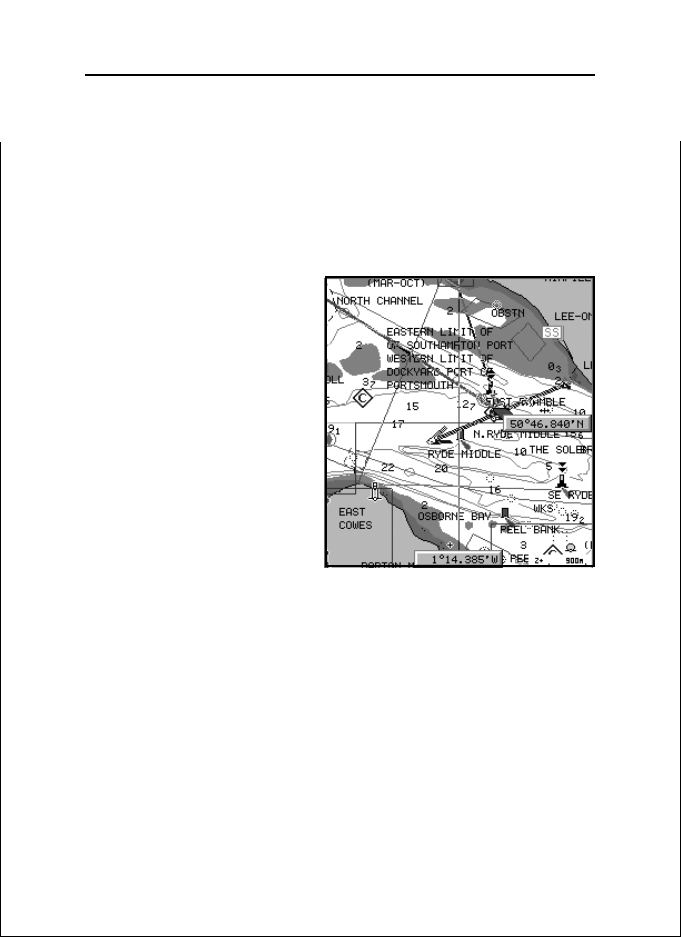
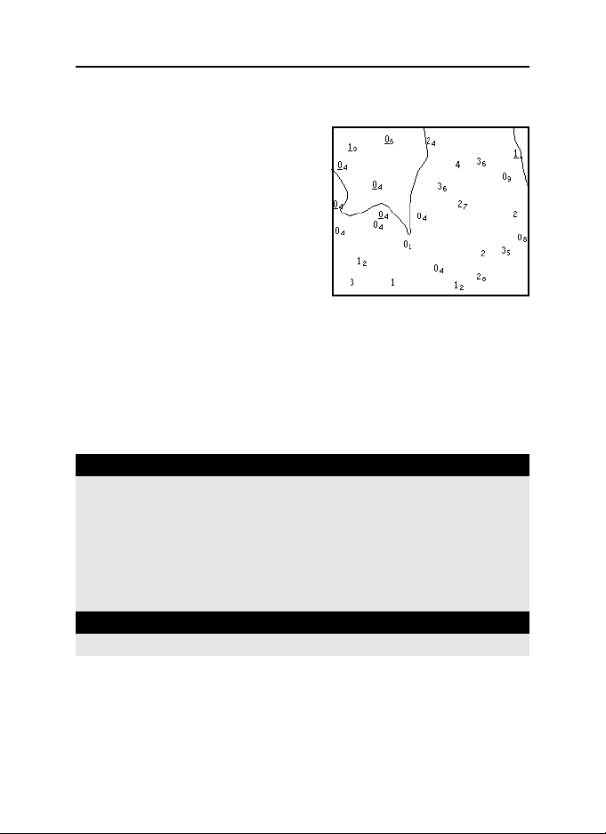
Converting depth values into the units
set
Press GOTO to display the menu,
select SETUP/GENERAL, DEPTH
UNITS and then set the unit desired in meters, feet or fathoms.
The GEONAV will convert all the
depth values in the unit selected,
making them appear like those reported in the official nautical
charts (see the figure).
Displaying abbreviated navaid characteristics
Position the manual cursor on the navaid symbol. A window
will show the abbreviated characteristics relative to the navaid
selected.
Description of navaid characteristics:
ABBREVIATIONS FOR LIGHT ABBREVIATIONS FOR COLOUR
AL alternating AM amber
F fixed B black
FLL fixed and flashing BL blue
FL (...) group flashing G green
FL single flashing OR orange
IQ interrupted quick R red
OC single-occulting VL violet
OC (...) composite group occulting W whit e
Q continuous group Y yellow
ABBREVIATION FOR PERIOD ABBREVIATION FOR RANGE
..S xx seconds ..M xx nautical miles
20
Displaying object attributes
Move the manual cursor on top of an object on the chart, then
press the joystick. A window will show the description of all
the objects present on the chart at the cursor’s position. Se-
English
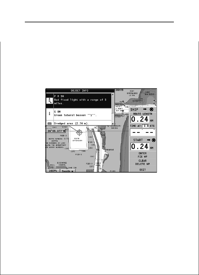
21
lect one object from this window and press the joystick to
show all of the object attributes.
The objects that can be queried include depth contours, depth
areas, point objects (lights, navaids, landmarks, etc.), land areas, spot soundings, coastlines, rocks, wrecks and, in general, any symbol present on the chart.
By querying the lights and navaids, the X-plain™ function
will give the description of the object in natural language,
thus avoiding the use of abbreviations and symbols difficult to
understand.
Chart presentation mode
The symbols used to represent the objects on the chart (buoys,
lights, landmarks, etc.), as well as chart colors, can be selected between paper-chart International or US styles.
English

NAVIONICS Electronic Charts
Press GOTO to display the menu, select SETUP/DISPLAY, then
PRESENTATION (INTER. or US).
Depth contours
This function allows the user to select the display of depth
contours; the options available are:
OFF: no depth contour displayed
5m: display of contours only with depths up to 5 meters
10m: display of contours only with depths up to 10 meters
20m: display of contours only with depths up to 20 meters
ALL: all depth contours displayed
Safety contours
This function allows the user to display the depth areas corresponding to the safety contour desired. The options available are:
OFF: no depth area displayed
2m: areas with depths up to 2 meters in dark blue
5m : areas with depths up to 2 meters in dark blue, up to
5 meters in blue
10m: areas with depths up to 5 meters in dark blue, up to
10 meters in blue
20m: areas with depths up to 10 meters in dark blue, up to
20 meters in blue
The areas whose depths are over the limit set, and therefore
navigable under safety conditions, will be displayed in white.
Dryline areas are always displayed in green.
22
NOTE: The mentioned colors are those used in the DAY mode. In NIGHT mode, the
areas with depths over the limit set, and therefore navigable under safety conditions,
are in black, whereas the colors below the limit are dark blue for higher depths and
blue for lower depths (e.g. 5m: areas with depths up to 2m displayed in blue, up to
5m in dark blue).
Displaying chart details
The display of spot soundings, landmarks and other chart
English
23
details can be selectively enabled or disabled from the SETUP/
DISPLAY/CHART DETAILS menu.
Displaying light sectors
The display of light sectors can be enabled or disabled from
the Setup menu.
Press GOTO to display the menu, select SETUP/DISPLAY, then
LIGHT SECTORS (AUTO/ON/OFF).
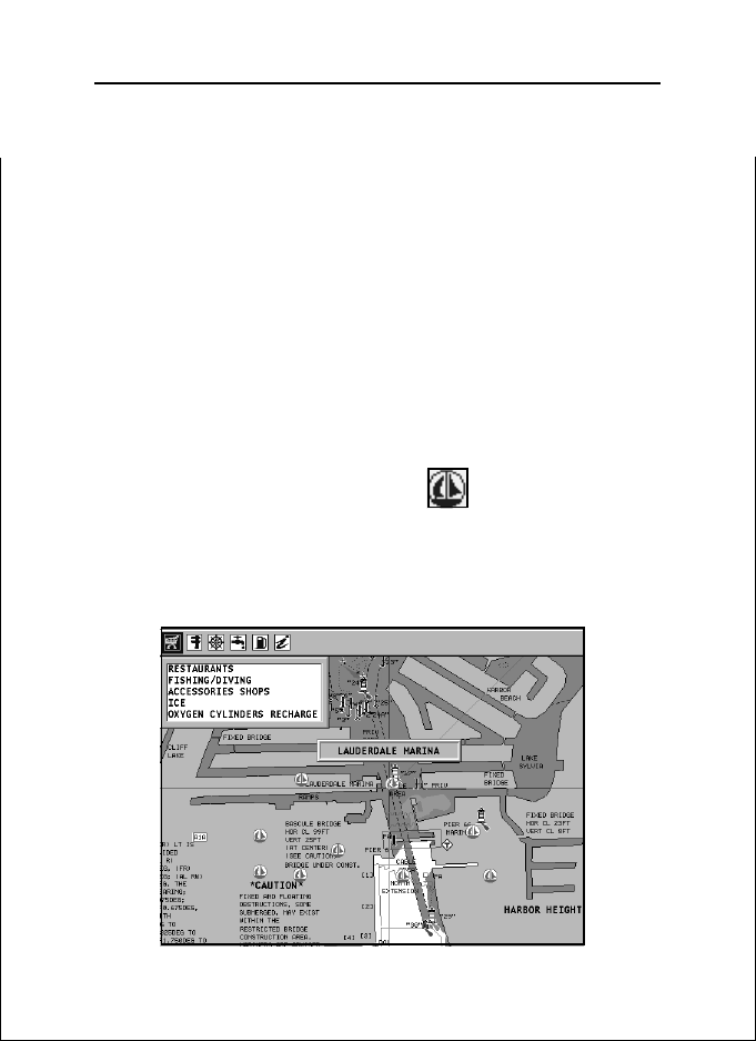
Displaying port services
NOTE: This function is available only with the NAVIONICS cartridges containing the
Port Services feature.
Position the cursor on the port icon and press ENTER.
A window will show the list of the port services available in
the port selected. Choose the service desired by the joystick.
The number and the type of icon differ from one port to another.
English
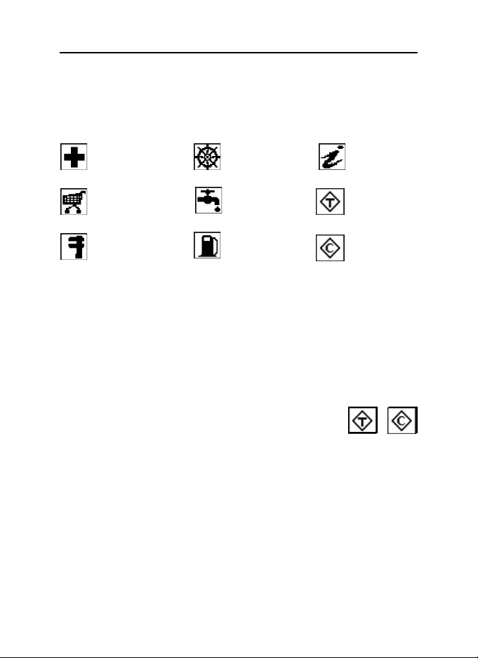
NAVIONICS Electronic Charts
Port services are identified by the following icons:
24
Health and first aid
services
T ourist services and
shops
Customer services
Water
Information
and port
authorities
Tide station
Engine, boat,
electronic and
Fuel
Current station
other repairs
The number and the type of service available will depend on
the cartridge installed.
Displaying Tides and Currents data
NOTE: This function is available only with the NAVIONICS cartridges containing
Tides and Currents data.
Position the cursor on the icon of a Tide or Current station, then press ENTER.
A graph will show the tide rate or the tidal stream relevant to
the station selected, as measured during the current day.
English
25
English
Graphic Items
26
GRAPHIC ITEMS
Besides chart data, the GEONAV displays some graphic items
useful during navigation.
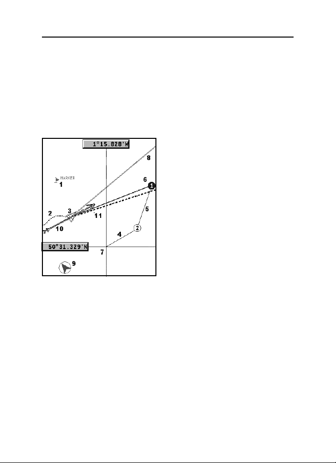
The figure below shows some of these items.
1 - Marker
Indicates a point of interest associated with a symbol, a name
and a color.
2 - Track segment
Recording of the track actually
followed by the boat; the track is
displayed as a colored dashed
line.
3 - Boat’s position
Boat’s position according to the
data received from the GPS receiver.
4 - Rubber band
Line joining the last waypoint entered to the manual cursor,
or the boat’s position to the manual cursor when no waypoint
has been entered.
To delete this band, press the EXIT key and switch to Navigation mode.
5 - Route leg
Part of route between two waypoints.
6 - Waypoint
Waypoints are identified by a circle and a number. The route
starting point is marked by the “X” symbol. The target waypoint
is identified by a filled circle, whereas the route leg currently
followed is identified by a thicker line.
English

27
7 - Cursor
Indicates the position expressed in geographical coordinates
(latitude and longitude).
It is displayed when the plotter is in Cursor mode.
8 - Heading vector
Indicates graphically the boat’s current route.
9 – North indicator
Indicates the north direction when the Chart rotation function is enabled.
10 – True wind vector
Indicates the direction of true wind detected by onboard instruments.
11 – Layline
Indicates the direction after the next tack or gybe. In order to
achieve the best performance, the tack or gybe should be carried out as soon as the layline crosses the target waypoint.
English

Functional Characteristics
28
FUNCTIONAL CHARACTERISTICS
This chapter describes some of the most important functions
of the GEONAV, as well as the terms most commonly used in
this document.
Switching on/Switching off the unit
To switch the GEONAV on, press the PWR key. To switch it
off, keep the PWR key pressed for more than 3 seconds.
Welcome page
At start-up, the GEONAV displays a welcome page whose text
(e.g., the boat’s name) can be edited by the Setup menu (see the
Setup Section). To freeze the page displayed, press ENTER. To
unfreeze the page and continue with the instrument’s operation, press ENTER again.
Depth sounder
If connected to a depth sounder via NMEA, the GEONAV will
enable the depth sounder mode, showing a graph of the sea
bed or the relevant data in numerical form.
The depth value can be expressed in meters (default value),
feet or fathoms; to select the unit, press GOTO, then choose
SETUP/GENERAL and DEPTH UNITS (M/FT/FA).
Sailing functions
If connected to a mast head transducer (anemometer), the
GEONAV will automatically enable the Sailing mode, once the
wind speed and direction data have been received, and provided that the Sailing window is enabled via the Setup menu.
Navigation mode (automatic)
At start-up, the GEONAV automatically enables the Navigation
mode, as soon as the GPS transmits a valid fix; when in Navigation mode:
• The manual cursor is not displayed
• The depth sounder window can be accessed
English

29
This mode is also called automatic because the unit automatically updates the boat’s position on the screen.
Cursor mode (manual)
When in Cursor mode, the manual cursor is displayed. It is
possible to insert, delete and move waypoints, insert and delete
markers, display navaid information, etc., but it is not possible
to gain access to the depth sounder window.
To switch from Navigation mode to Cursor mode, use the
joystick. To go back to Navigation mode, press the EXIT key.
Chart rotation
Charts are traditionally displayed in north-up mode. This,
however, does not correspond to reality. For example, when
traveling southwards, the chart shows, on the right side of
the boat, what is actually located on the left side, and vice
versa.
Without Chart Rotation
With Chart Rotation
The Chart Rotation function allows rotating the electronic chart
displayed according to the plotted route (COG - Course Over
English

Functional Characteristics
Ground), as detected by the GPS receiver. Since the COG value
varies continuously, a filter has been inserted to prevent the
chart from bouncing.
The Chart Rotation function is enabled at a speed greater than
1 knot. To enable the Chart Rotation function, press GOTO,
select SETUP/DISPLAY, then CHART ROTATION and ON. A
message will prompt the user to select the chart scale before
activating the chart rotation. Confirm by pressing ENTER.
The northern direction will be indicated by the symbol
Autozoom
With the Autozoom function the GEONAV will always display
automatically the boat’s position and the target waypoint at
the best available chart scale. This function is enabled provided that at least one waypoint has been previously entered.
30
To enable the Autozoom function, press ZOOM+ until the
“AUTOZOOM ? ENTER = YES” message is displayed, then
confirm by pressing ENTER. To disable the Autozoom function,
press ZOOM.
When the GEONAV is turned on, and if at least one waypoint
has been previously entered, the Autozoom function will be
automatically enabled.
Screen Amplifier
This function automatically redraws the chart according to
the boat’s course, so as to maintain 2/3rds of the screen ahead
English

31
of the boat, provided that the boat’s speed is greater than 3
knots. This function will be enabled provided that no waypoint
has been previously entered.
EBL/VRM functions
The EBL (Electronic Bearing Line) and VRM (Variable Range
Marker) functions allow entering markers and waypoints as
range and bearing coordinates with respect to the current position.
To enable these functions, rotate the knob to display the EBL,
position the line on the bearing desired, then press the knob
English

Functional Characteristics
to enable the VRM ring and adjust its size by rotating the knob
so as to reach the range desired. To edit the values set, press
the knob to switch from the VRM function to the EBL function.
To insert a waypoint where the EBL and VRM intersect, press
ENTER; to insert a marker, hold ENTER pressed.
Range and bearing values are displayed in the lower righthand side of the screen, together with the indication of the
function currently enabled.
Press CLR to disable the two functions in sequence.
The VRM ring can also be used to set the range for navigation
from the coast, for example to avoid navigating out of the limit
allowed. In this case, set the EBL to any value, adjust the
VRM ring size as desired, then navigate making sure that at
least one point in the ring is always touching the coast.
Easy Pilot function
The Easy Pilot function allows editing temporarily a route set and followed by the autopilot,
but keeping the route unchanged. This function is useful to make corrections at once (e.g.,
because of other boats or to approach points of
interests), without having to edit the route
planned or disable the autopilot.
32
To enable this function, rotate the knob and
position the EBL on the new route to follow,
then press ENTER. The EBL will change color,
as the boat starts following the new route; the
planned route will be abandoned, although displayed. To go back to the planned route, thus
canceling the temporary correction, press CLR.
NOTE: The Easy Pilot function can be enabled only if a route is present.
English

33
Overzoom
The Overzoom function allows expanding the chart range.
The Overzoom does not provide any additional chart detail,
only improves the readability of the available information, acting as a magnifying glass.
When the Overzoom is enabled, the unit will add OVZ to the
scale displayed in the Navigation window.
To enable/disable the Overzoom function, press GOTO to display the menu bar, then select SETUP/DISPLAY, OVERZOOM
and ON/OFF.
Position calibration
All position sensors are affected by intrinsic errors that make
the boat’s position incorrect (from few meters to several hundred meters).
The position calibration function allows correcting manually
the position error present in all GPS, provided that this error
is not greater than 2 nautical miles.
Press GOTO and then, by using the joystick, select SETUP/
NAVIGATION, CALIBRATION and then ON. A message will
prompt the user to move the cursor to the boat’s true position,
appropriately enlarged by the ZOOM+ key.
Press ENTER to move the GPS boat’s position to the point indicated by the cursor. This operation will save the calibration
for use in future calculations.
NOTE: When the calibration is enabled, the coordinates (latitude/longitude) in the
General Info window will be marked by (*).
To cancel the calibration, press GOTO, select SETUP/NAVIGATION, CALIBRATION and then OFF.
Local time
This function allows entering local time instead of the Greenwich time (GMT) supplied by the GPS receiver.
English

Functional Characteristics
To enter local time, press GOTO and then, by using the joystick, select SETUP/NAVIGATION, SET TIME and then LOCAL.
The joystick will allow entering local time as well as confirming and saving the operation. To cancel local time, press GOTO,
select SETUP/NAVIGATION, SET TIME and then GMT.
Contrast/Brightness
Press the PWR key to display the CONTRAST/LIGHT window.
Use the joystick to switch from one option to the other and to
adjust the contrast/brightness level.
Press ENTER to exit.
Color
Besides displaying color nautical charts, the GEONAV allows
selecting the track and marker colors.
Press the GOTO key to access the menu, select TRACK or
MARKER, then COLORS and confirm by pressing ENTER; choose
the color desired and confirm the selection.
The color of markers can also be selected when entered or
edited, whereas the track segment color can be selected by
positioning the manual cursor on the segment itself.
The color of chart items can be chosen from DAY, NIGHT or
BRIGHT. Press GOTO to display the menu, select SETUP/DISPLAY, MODE and then DAY, NIGHT or BRIGHT.
34
Anchor alarm
This function allows generating an anchor alarm message that
warns the user when the ship moves farther than the selected distance from its anchoring position, that is the ship’s
position when the alarm is enabled. The reference distance
value for the alarm can also be set. After the alarm is issued,
press any key to reset it by using the current ship’s position
as the new anchor position. To set this function, press GOTO,
select SETUP/NAVIGATION and then ANCHOR ALARM.
English

35
ARPA
Your GEONAV allows displaying the position of targets tracked
by any radar featuring the ARPA (Automatic Radar Plotting
Aid) or MARPA (Mini-ARPA) function.
To activate the ARPA display function select ACTIVATE from
the GOTO/SETUP/ARPA menu. When the ARPA display function is active, the instrument shows the target data received
from the ARPA radar connected to the plotter through the
NMEA0183 port.
ARPA target representation
The figure below shows a sample of tracked ARPA targets.
The following graphic items are displayed:
1 - Target name
The name of the target being tracked.
English

Functional Characteristics
2 - Vector
Shows the current direction of the target. The longer the vector, the faster the target.
3 - Marks
Each mark provides the forecasted position of the target - based
on its own current speed and direction - every minute.
4 - Thicker mark
The last mark - thicker than the others - shows the forecasted
position of the target - based on its own current speed and
direction - after six minutes.
5 - Target shape
The target shape provides information on the target tracking
status. The status can be:
- Target being tracked (still in process of acquisition)
- Target being tracked (steady, i.e., currently tracked ok)
36
- CPA/TCPA warning: target falls within the CPA/TCPA lim-
its
- Target lost
English

37
NOTE: When the ARPA function is active, the own ship vector shows the six marks
- like the target vectors - providing the forecasted position of the own ship every
minute for the next six minutes.
ARPA target information
To display the information concerning any ARPA target, move
the cursor on the target icon and press ENTER.
A window containing the information on the target will show.
CPA/TCPA limits
Press the GOTO key, select SETUP, then ARPA. Choose the
SET CPA/TCPA LIM. option to set the CPA (Closest Point of
Approach) and TCPA (Time to Closest Point of Approach) limits.
As soon as the CPA or TCPA parameters of a target become
lower than the selected limits, a warning message is issued.
Radar offset
Press the GOTO key, select SETUP, then ARPA. Choose the
English

Functional Characteristics
OFFSET GPS RADAR option to recall the menu that will allow
setting the position of the radar antenna with respect to the
GPS antenna, so as to improve the accuracy of target representation.
38
English

Quick Tour
39
QUICK TOUR
We recommend that you use the GEONAV intuitively, since
no damage will be caused by pressing an incorrect button.
Make sure that the
GPS receiver is connected, insert a
Compact Flash™
cartridge and press
the PWR key. At
start-up, the last
chart used will be
loaded by default.
If the chart is not found, the list of NAVIONICS charts stored
into the Compact Flash™ cartridge will be displayed. Select
the desired chart by the joystick, then confirm by pressing
ENTER. A message will warn the user that electronic nautical
charts do not replace official government charts.
Press the PWR key to turn the display backlight on and adjust
the brightness by the joystick; press ENTER to continue (enabling the Geonav mode).
The Satellite window will show the configuration of the satellites in use. As soon as the GPS receiver has obtained a
valid fix (it can take a few minutes), the boat’s position and
the relevant area will be displayed at the best scale available.
The default language is English. To change the language, press
GOTO to display the menu, then select SETUP/GENERAL, LANGUAGE and the desired language by the joystick.
The line, or vector, starting from the boat indicates the boat’s
direction, to be ignored if the boat is stationary.
Windows will display the boat’s speed, route, chart scale and
local time.
English

Quick Tour
The GEONAV is in Navigation mode; by the joystick, it is
possible to switch to Cursor mode (editing mode). The cursor
position is shown by two windows. The joystick allows moving in all directions.
To plot a route starting from the boat’s position, move the cursor to the position desired and press ENTER to insert a waypoint,
that will be indicated by a circle containing the number 1.
The windows will also show the time to reach the target
waypoint, distance, bearing and estimated time to arrive.
Press the EXIT key to go back to Navigation mode.
40
To add more waypoints, enter the Cursor mode by using the
joystick and repeat the operations described above.
As new waypoints are added, the numbering will increase
progressively. In case of error, waypoints can be deleted by
pressing the CLR key (Cursor mode), starting from the last entered. To go back to Navigation mode, press EXIT.
English

41
If an autopilot is connected to the GEONAV, the plotted route
is automatically followed as soon as the Navigation mode is
enabled.
NOTE: The cursor can be moved to the desired position by using the GOTO functions
as well. See the GOTO Section for more details.
The NAVIONICS Gold™ charts provide detailed information
that can be displayed at any time.
By using the joystick, position the cursor on the chart item
desired (symbol for light, buoy, depth area, etc.) and then press
the joystick; the information relative to the items situated in
that given position will be shown.
Use the joystick to scroll the information list, then press EXIT
to exit and select another item. Press EXIT again to go back to
Navigation mode.
English

Operating Modes
42
OPERATING MODES
When switching on the GEONAV, the user can select one of
the two main operating modes available.
Press the PWR key and wait for the message on official nautical charts to show (if required, select one chart among those
contained in the cartridge), then press EXIT to enable the STD
mode, or ENTER to enable the standard GEONAV mode. It is
also possible to press GOTO to enter the demo mode, in which
the unit automatically shows, in sequence, different views
relative to the chart currently loaded.
STD mode
This mode allows displaying the chart data according to the
RTCM standard. During navigation, only the ship’s position,
the heading vector and a set of chart items - defined by the
applicable regulations (and known as standard display) - are
displayed at full screen. Markers are not displayed and navigation data are made accessible only by quitting the standard
display. By enabling the manual cursor by the joystick, the
markers will show again, on condition that the relevant option on the Setup menu (DISPLAY/MARKERS ON/OFF) has
been selected.
Geonav mode
This is the unit standard mode. During navigation, the windows showing position and route (if present) data, as well as
the waypoints and markers, are enabled.
It is not possible to disable the marker display, whose relevant option does not appear in the Setup menu.
In Geonav mode, the unit displays different types of data,
according to the operating mode enabled (Cursor mode or Navigation mode). The following paragraphs will describe the differences between the modes available.
English

43
CURSOR MODE
To plan a new route, or to append waypoints to the existing
route, move the cursor by using the joystick and press ENTER.
The GEONAV will display the following data:
• Route overall length
• Time to the end of the route (estimated on the speed value
manually entered in the ROUTE menu; see the Route Section)
• Distance from the last waypoint to the cursor
• Chart scale
To edit the existing route, move the cursor by using the joy-
stick. The GEONAV will display the following data:
• Distance from the boat’s position to the cursor
• Time to arrive to the cursor
• Bearing from the boat’s position to the cursor
• Chart scale
Now it will be possible to move the cursor on a route item to
edit it, or press ENTER to lengthen the route by appending new
waypoints.
English

Operating Modes
NAVIGATION MODE
By pressing the EXIT key repeatedly, it will be possible to access the several windows available, provided that they have
been previously enabled by the appropriate option of the Setup
menu.
When the fix is valid and no route is present, the window
sequence is the following:
44
NAVIGATION > DEPTH SOUNDER > TRIP > SATELLITE > GENERAL
INFO > TIDE INFO > RUNWAY
When a route is present, the window sequence changes as
follows:
SAILING > NAVIGATION > DEPTH SOUNDER > TRIP > SATELLITE >
GENERAL INFO > TIDE INFO > RUNWAY
The Depth Sounder window is displayed provided that data is
received from a depth sounder.
If data is received from the wind instrument, an arrow on the
ship’s position will indicate the true wind direction and, if a
route is present, the Sailing windows will be displayed.
The Tide Info window is displayed provided that a NAVIONICS
cartridge featuring Tides and Currents data is active (see the
Tide Info Window Section).
CHART ONLY MODE
To hide the Navigation windows and display a full screen
chart, press GOTO and EXIT at the same time.
Press any key to show the windows again.
English

Navigation Windows
NAVIGATION WINDOWS
These windows are automatically enabled as soon as the GPS
receiver has obtained a valid fix (FIX OK).
If no route has been entered, the following data will be shown:
45
• Boat’s speed
• Chart scale
• Course
• Sea depth (if available)
• Water temperature (if available)
• Local time
To change the chart scale, press the -ZOOM+ key.
English

Navigation Windows
If a route has been entered, the Navigation window will show
the following data:
46
• Boat’s speed
• Chart scale
• Target waypoint
• Distance to the target waypoint
• Time to arrive to the target waypoint
• Estimated time to the route end
• Sea depth (if available)
• Water temperature (if available)
NOTE: To display sea depth and temperature values, the GEONAV must be interfaced with a depth sounder.
English

Sailing Windows
SAILING WINDOWS
These windows are enabled automatically as soon as the GPS
receiver has obtained a valid fix (FIX OK), data is received
from the wind instruments, a route is present and provided
that they have been enabled via the Setup menu.
They display the following information:
47
• Boat’s speed
• Chart scale
• Target waypoint
• Distance to the target waypoint
• Bearing to the target waypoint
• Angle to steer
• Sea depth (if available)
• Water temperature (if available)
English

Sailing Windows
48
• True wind speed
• True wind direction (magnetic)
If more waypoints are present, besides the target waypoint, a
window will show the apparent wind data on the next leg.
The apparent wind speed is indicated by the digits in the
center of the window. The wind direction is represented
graphically by an arrow.
If a close hauled or a run is planned on the next leg, the
arrow will indicate the direction of apparent wind on the first
beat of the next leg, whilst the direction of apparent wind on
the waypoint will be represented by a single line. The bearing
to the following waypoint is also shown.
English

Depth Sounder Window
49
DEPTH SOUNDER WINDOW
This window, displayed if the GEONAV is interfaced with a
depth sounder, replaces the number indicating the sea depth
in the Motor Boating windows with a graph showing the sea
bed. If received, the graph shows the water temperature as
well.
When navigating in waters deeper than sounder operating
range or if the boat’s speed is too high for depth sounding,
data acquisition will be interrupted and the number replaced
by “—”.
English

Trip Window
TRIP WINDOW
The Trip window shows general data relating to the route
followed.
50
• Average speed from departure
• Maximum speed from departure
• Time elapsed from departure
• Partial distance covered from departure
• Overall distance covered
To reset all counters (except for the overall distance) before
starting a new journey, press the CLR key.
English

Satellite Window
51
SATELLITE WINDOW
At start-up the satellite window displays
how many and which
satellites are tracked
by the GPS receiver.
The outer circle represents the horizon,
the inner one identifies a 45° elevation
with respect to the
horizon, and the central circle points to
the zenith.
The small squares
with numbers show
the satellites available.
As soon as a satellite is tracked by the GPS receiver, the number inside the square is displayed in reverse. The bars displayed on the left identify the signal quality; the longer the
bar, the higher the signal quality.
On the left of each bar, two digits indicate numerically the
signal/noise ratio.
Additional information:
• Day, month, year, local or Greenwich time (at the first
start-up the GEONAV is initialized to Greenwich Time).
• Boat’s position (lat/lon) (or the latest valid fix if the GPS
receiver is still searching for satellites).
• Data on the current satellite situation (number and fix).
• SOG, COG and altitude.
English

Satellite Window
The latitude and longitude values relevant to the boat’s position are displayed as soon as three satellites are tracked and a
2D fix (two dimensions) is available.
The altitude value is available only if four satellites are tracked
and a 3D fix is obtained.
As soon as a valid fix is available, the GEONAV will automatically switch to Navigation mode and display the boat’s position at the best chart range available; the window at the bottom of the screen will indicate the boat’s course and speed.
To recall the Satellite window, press the EXIT key repeatedly
until it appears.
52
English

General Info Window
53
GENERAL INFO WINDOW
This window displays the following information on the boat’s
current position:
• Geographical coordinates
(latitude/longitude)
• The position correction ap-
plied to the latitude and longitude (SETUP/NAVIGATION, CALIBRATION option)
• Magnetic variation value re-
ceived by the GPS
• Course (COG)
• Speed (SOG)
NOTE: This window is available in Navigation mode only.
English

Tide Info Window
54
TIDE INFO WINDOW
When a NAVIONICS cartridge featuring Tides and Currents
data is present, this window displays further information,
besides the forecast data supplied by selecting the Tides and
Currents station.
The following data is displayed:
• Latitude and longitude at the
current boat’s position
• Current time and date
• Value of magnetic variation
received by the GPS
• Dawn and sunset time
• Moonrise and moonset time
• Moon phase
• Graph of estimated tide level
with respect to the current
position
WARNING: Unlike the graph displayed at a T&C station position (accessible through
the GOTO function, or by positioning the cursor on the Tides and Currents station
symbol) that is accurate since it is supplied by hydrographic offices, this graph
shows estimated data, being the result of interpolation between the two Tides and
Currents stations nearest to the point of interest. The accuracy of the estimate may
vary, depending on the coast type, the distance to the nearest stations, and other
geographical features.
English

Runway Window
55
RUNWAY WINDOW
This window displays the following information on the target waypoint:
• Name of the target waypoint
• Distance from the target
waypoint
• Estimated time of arrival to
the target waypoint
• Bearing
• Course
• Steering angle
• XTD (right/left distance
from the planned route)
• XTD limit (runway width)
The graph shows the boat’s position with respect to the route.
When the XTD reaches the extreme value shown in the lower
right-hand corner of the window, the boat symbol will reach
the runway right or left side.
To change the XTD limit, see the Setup Section.
NOTE: This window is available in Navigation mode only.
English

Main Menu
56
MAIN MENU
The main menu bar, that appears when pressing the GOTO
key, allows accessing the following options:
ROUTE: To display route information, reverse and delete the
route, set the consumption data and save or read data from the
cartridge.
TRACK: To enable/disable the track function, delete a track,
choose the track color, show the used percentage of track
memory and save or read data from the cartridge.
MARKER: To delete markers, choose the marker color, show
the number of markers used and available, and save or read
marker data from the cartridge.
GOTO PORT: To plan a route to a selected port.
GOTO NEAREST: To plan a route to the nearest port service.
SETUP: To enable/disable and change the plotter’s setup.
GOTO LAT/LON: To plan a route to a known geographical posi-
tion.
GOTO RANGE/BEARING: To plan a route to a position whose range
and bearing values are known.
NOTE: The majority of menu items, once selected, show a series of submenus. Use
the joystick to move from one menu to another and press ENTER to choose one item.
English

Route
57
ROUTE
EDITING A ROUTE (CURSOR MODE)
Creating a waypoint
Using the joystick, move the cursor on the position desired
and press ENTER to insert a waypoint.
To enter further waypoints, move the cursor and press ENTER.
The new waypoint will be appended to the existing route.
Up to 99 waypoints per route can be entered, also by using the
GOTO functions available from the main menu.
Deleting the last waypoint
Press CLR. If the last waypoint is out of screen, the “DELETE
WP? ENTER = YES” message will be displayed.
Press ENTER to confirm the deletion.
Deleting a waypoint
Use the joystick to position the cursor on the waypoint to
delete and press the CLR key.
Deleting all waypoints in a route
Press the CLR key repeatedly until the “NO WP PRESENT”
message is displayed.
Moving a waypoint
Position the cursor exactly on the waypoint to move; press
ENTER to capture the waypoint, then move the waypoint to the
position desired and confirm the operation by pressing ENTER.
Inserting a new waypoint in a route
Position the cursor exactly on the route leg to edit and press
ENTER to capture the leg.
Once captured, the leg will show a thicker line to distinguish
it more easily from the other route legs. A window will also
show the leg captured and its length.
Move the manual cursor to the position desired, insert the
new waypoint and confirm by pressing ENTER.
English

Route
EDITING A ROUTE (NAVIGATION MODE)
If the manual cursor is displayed, press the EXIT key to enter
Navigation mode.
Changing the target waypoint
Use the “Route to a waypoint” function (see the Functions in
the Route Menu Section).
WARNING: The route will be modified and the new target waypoint selected will be
the first waypoint in the route.
Deleting all waypoints
Press the CLR key to show the “DELETE ROUTE? ENTER =
YES” message. Press the ENTER key to confirm the deletion or
another key to exit.
FUNCTIONS IN THE ROUTE MENU
Route Info
Route information is displayed on several adjacent pages containing general route information and the geographical coordinates of all waypoints. Press GOTO to display the main menu,
then select ROUTE. A window will show the following information:
58
English

59
WP NAME : Waypoint name
DISTANCE: Distance from START to current waypoint
TIME: Estimated time from START to current waypoint
FUEL LITERS: Estimated fuel consumption (liters or gallons)
BRG: Bearing from previous waypoint to current waypoint
POSITION: Waypoint latitude / longitude
The time to arrive to the waypoint and fuel consumption are
displayed provided that estimated speed and fuel consumption values have been entered (see the Entering speed and fuel
consumption data Section).
To move within the page and scroll the adjacent pages, use
the joystick. To go back to the menu, use the joystick; to exit,
press the EXIT key.
Entering speed and fuel consumption data
The data are used to calculate the values displayed in the
ROUTE window.
Press the GOTO key to display the menu, select ROUTE/SPEED/
CONS. and press ENTER. Use the joystick to enter the data
required and to confirm the operation.
Storing a route in the CompactFlash™
Press the GOTO key to display the menu, select ROUTE, STORE
and press ENTER. To change the default name, use the joystick. To confirm the operation, press ENTER.
The “ROUTE STORED” message will confirm that the route
has been stored correctly. Once stored, the route will disappear from the screen.
Recalling a route from the CompactFlash™
Press the GOTO key to display the menu, select ROUTE, RECALL and press ENTER to open the route catalog; select the
route by the joystick and then press ENTER to confirm, or EXIT to
exit.
English

Route
The route recalled will be displayed, the Autozoom function
automatically enabled and a window will allow selecting the
target waypoint.
Deleting a route
Press the GOTO key to display the menu, select ROUTE, DELETE and press ENTER to confirm.
The catalog that lists the routes stored in the CompactFlash™
will show the CURRENT item indicating the route currently
displayed.
60
Select the route to delete by the joystick, then press ENTER to
confirm. By selecting CURRENT, the route currently displayed
will be deleted; the route can also be deleted by keeping the
CLR key pressed for 3 seconds in Navigation mode.
Reversing a route
Press the GOTO key to display the menu, select ROUTE and
then REVERSE (if no route is currently displayed, the “NO
English

61
ROUTE PRESENT” message will appear).
The waypoint order will be automatically reversed allowing
navigation in the opposite direction.
Route to a waypoint
Press the GOTO key, select ROUTE and move the cursor within
the waypoint list by using the joystick. Press ENTER and select
the target waypoint by the joystick. Press ENTER to confirm the
selection, or EXIT to exit.
As the GEONAV will plot a new route, the waypoint selected
will become the first waypoint in the route, whereas previous
waypoints will be deleted.
English

Track
62
TRACK
The Track function allows recording the track actually followed by the boat. The Track function can be enabled and
disabled several times during navigation; in this case, separate track segments will be drawn.
Starting a track
To enable the Track function, press the GOTO key to display
the main menu, select TRACK, START and press ENTER to
confirm. A small circle on the boat’s position will indicate the
track starting point.
Stopping a track
To disable the Track function, press the GOTO key to display
the main menu, select TRACK, STOP and press ENTER to confirm.
Storing a track in the CompactFlash™
Press the GOTO key to display the main menu, select TRACK,
English

63
STORE and press ENTER to confirm. To change the default file
name, use the joystick. To confirm the operation, press ENTER.
The “TRACK STORED” message will confirm that the track
has been stored correctly. Once stored, the track will disappear from the screen.
Each time a track is stored in the CompactFlash™, the plotter’s
memory is cleared and the indicator of memory used in the
TRACK menu is reset to 0%.
Recalling a track from the CompactFlash™
Press the GOTO key to display the main menu, select TRACK
and then RECALL to open the track catalog.
Select the track desired, then press ENTER to confirm the operation or EXIT to exit.
Deleting a track
Press the GOTO key to display the main menu, select TRACK,
DELETE and press ENTER to confirm.
The catalog that lists the tracks stored in the CompactFlash™
will show the CURRENT item indicating the track currently
displayed.
Select the track to delete by the joystick, then press ENTER to
confirm. By selecting CURRENT, the track currently displayed
will be deleted.
Setting the track color
The track color can be selected from the menu; press the GOTO
key to display the main menu, select TRACK, COLORS, choose
a color by the joystick and confirm the selection by pressing
ENTER. The selected color will be stored together with the track.
NOTE: The track color cannot be changed while the recording is active.
English

Track
Displaying and changing track segment data
Position the manual cursor on a point in the track segment.
A window will show the navigation data recorded in that position.
• Recording date
• Recording time
• Sea depth
• Water temperature
• True wind direction
• True wind speed
Wind and depth values are displayed only if available.
By positioning the manual cursor on the starting point of a
track segment, a menu will allow changing the segment name,
displaying average/maximum speed data, trip length/time, deleting the single segment as well as changing the single segment color.
When the menu pops up, press ENTER to access the options,
then use the joystick to select the desired option and press
ENTER to confirm.
64
Route to a track segment
Press the GOTO key and select TRACK by the joystick. A window will show, for each track segment, the line color, the
name, the recording start date and time as well as the recording duration and length.
The list can be sorted by using the joystick to select the sort
field and to confirm. Use the joystick to select the target
segment (the latest 8 segments used will be highlighted) from
the catalog and then press ENTER to confirm.
English

65
The GEONAV will position the manual cursor at the beginning of the track segment selected; insert a waypoint by pressing ENTER, or a marker by holding ENTER pressed.
English

Markers
66
MARKERS
Markers are used to identify points of interest to which names
and symbols can be assigned.
When a marker is entered, the plotter records also date, time
and sea depth and temperature (if available). This data is stored
together with the marker name, symbol and color and can be
displayed in the window shown by the GOTO MRK menu.
NOTE: Marker names are displayed starting from the 32 NM chart scale.
CURSOR MODE
Inserting a marker
Move the cursor to the position desired
and hold the ENTER key pressed. A window will display the symbol and a name
automatically assigned to the marker.
Use the joystick and the -ZOOM+ key to change the marker
symbol (8 symbols available), name (max. 8 characters) and
color according to the type of marker to store (e.g., fishing
spots, wrecks, rocks, etc.). Press ENTER to confirm the insertion.
NOTE: The cursor can be moved to the desired position also by using the GOTO
functions.
Changing a marker name/symbol/color
Position the cursor on the marker desired and press ENTER; a
window will display the symbol, the name and the color previously assigned to the marker selected. Use the joystick and
the -ZOOM+ key to change the marker name, symbol and color.
Press ENTER to confirm the operation.
Deleting a marker
Position the cursor on the marker to delete and press CLR.
English

67
NAVIGATION MODE
Inserting a marker
Hold the ENTER key pressed to insert a marker at the boat’s
position. A window will display the symbol and the name
automatically assigned to the marker; to change the marker
symbol, name and color according to the type of marker to
store (e.g., fishing spots, submerged wrecks, rocks, etc.), use
the joystick and the -ZOOM+ key. Press ENTER to confirm the
insertion.
Route to a marker
Press the GOTO key and select MARKER by the joystick. The
catalog displayed will list, with respect to each marker, the
symbol, the name, the insertion date/time, as well as, if available, the sea depth and temperature values as detected when
entered.
Moreover, the catalog shows the number of markers entered
in the current page and the number of markers still available.
The list can be sorted by using the joystick to select the sort
English

Markers
field and ENTER to confirm.
By using the joystick, choose the desired marker (the latest 8
markers used will be highlighted) from the catalog displayed,
then press ENTER to confirm.
Once the desired marker has been selected, the GEONAV will
insert a waypoint at the marker position and append the new
leg to the existing route (if no route is available, the new
waypoint will be connected to the boat’s position).
Press the EXIT key to go back to Navigation mode and enable
automatically the Autozoom function.
NOTE: To delete a single marker, select it from the GOTO Marker list and press the
CLR key.
FUNCTIONS IN THE MARKER MENU
Storing a set of markers in the CompactFlash™
Press the GOTO key to display the menu, select MARKER, then
STORE and press ENTER. Use the joystick to change the default name and press ENTER to confirm the operation.
The “MRK. STORED” message will confirm that markers have
been stored correctly. Once stored, markers will disappear
from the screen.
Each time a set of markers is stored in the CompactFlash™,
the plotter memory is cleared and the indicator of the markers
available is reset to the maximum value.
68
Recalling a set of markers from the CompactFlash™
Press the GOTO key to display the menu, select MARKER and
then RECALL to open the marker catalog.
Select the marker set desired by using the joystick, then press
ENTER to confirm the operation, or EXIT to exit.
Deleting a set of markers
Press the GOTO key to display the menu, select MARKER, DE-
English

69
LETE and press ENTER to confirm.
The catalog that lists the sets of markers stored in the
CompactFlash™ will show the CURRENT item indicating the
set currently displayed.
Use the joystick to select the set of markers to delete and
press ENTER to confirm. When selecting CURRENT, the set of
markers currently displayed will be deleted.
English

Goto Port
70
GOTO PORT
Press the GOTO key and select PORT by the joystick. Choose
the desired port (the latest 8 ports used will be highlighted)
from the catalog displayed, then press ENTER to confirm.
To scroll the list of ports quickly, press the -ZOOM+ key.
It is also possible to type the first letters of the port name by
using the keyboard located in the lower part of the screen.
Use the joystick to move the cursor down to the last item of
the list, then move the cursor down again to gain access to
the keyboard.
Use the cursor to select the characters, then confirm with
ENTER. Once the port of interest is shown in the list above,
use the joystick to highlight it and press ENTER to confirm.
Once the desired port has been selected, the GEONAV will
insert a waypoint in the port position and append the new leg
to the existing route (if no route is available, the new waypoint
will be connected to the boat’s position).
Press the EXIT key to go back to Navigation mode and enable
automatically the Autozoom function.
English

Goto Nearest
71
GOTO NEAREST
NOTE: This option is available only with the NAVIONICS cartridges containing the
Port Services features. It allows finding and heading for the nearest port featuring the
service desired.
Press the GOTO key, select NEAREST by the joystick, choose
the desired service and press ENTER to confirm, or EXIT to cancel the operation.
The GEONAV will show the three destinations closest to the
boat’s position (if in Navigation mode), or to the cursor’s position (if in Cursor mode), and position automatically on the
closest destination (flashing).
Select one port at a time by using the joystick; a window will
show the distance and time to arrive (estimated on the boat’s
current speed). Press ENTER to confirm the selection.
The GEONAV will insert a waypoint in the port selected, delete automatically the existing route (if in Navigation mode), or
append the waypoint to the existing route (if in Cursor mode),
English

Goto Nearest
then go back to Navigation mode and enable automatically the
Autozoom function.
Tide or current forecast at the nearest survey station
NOTE: This function is available only with the NAVIONICS cartridges containing
Tides and Currents data.
This function allows displaying, within the space of twentyfour hours with respect to the selected date, the tide level and
tidal current speed and direction at a survey station in the
vicinity. Unlike the estimated data shown in the Info window, this forecast is much more accurate, being supplied directly by tidal surveying stations.
Press the GOTO key, select NEAREST by the joystick, choose
the Tides or Currents service, then press ENTER to confirm.
The GEONAV will allow selecting one of the three nearest
Tides and Currents stations. Use the joystick to choose the
station desired, then press ENTER to confirm. A window will
show the information reported below.
72
English

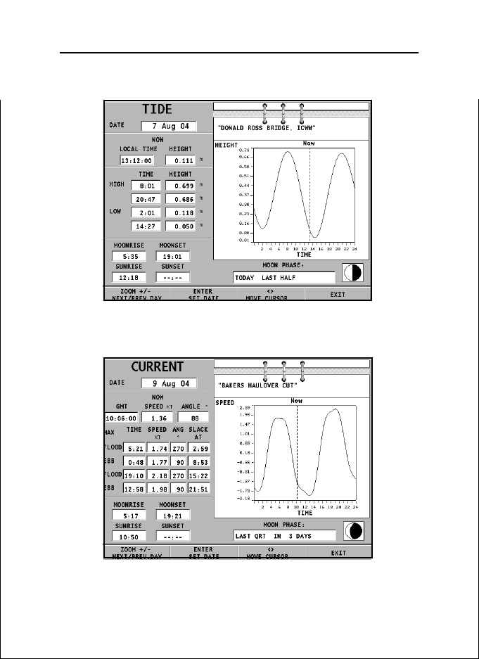
73
Tide station
• Name of the station
• Forecast reference date
• Time and height with respect to the cursor’s position in
the graph
• Time and height of high/low water
• Dawn and sunset time
• Moonrise and moonset time
• Moon phase
• Tide level graph (24 hours)
Tidal current station
• Name of the station
• Forecast reference date
• Time, speed and direction with respect to the cursor’s po-
sition in the graph
• Time, speed, direction and slack time of daily flood and
ebb streams
• Dawn and sunset time
• Moonrise and moonset time
• Moon phase
• Tide level graph (24 hours)
In the both cases above, the default date is today. A different
date can be set by pressing ENTER or -ZOOM+.
NOTE: The same information can be accessed by positioning the manual cursor on
the icon of a Tides or Currents station, and pressing ENTER to confirm.
English

Goto Nearest
74
English

Setup
75
SETUP
The Setup menu allows setting the available options.
To access the Setup menu, press GOTO to display the main
menu, then select SETUP by using the joystick.
The menu items are grouped in six sets.
When selecting a set by the joystick, the
list of the available options will be displayed. Press ENTER to select one set, then
use the joystick to switch from one option
to another and edit the setting. To go back
to the set list, press EXIT.
DISPLAY
• Mode (BRIGHT/DAY/NIGHT)
Selects the colors suitable for the environment.
• Safety Contours (OFF/2m/5m/10m/20m)
Enables the display of the areas corresponding to the depth
safety contour.
• Depth Contours (ALL/5m/10m/20m/OFF)
Selects the display of depth contours.
• Easy View (ON/OFF)
Enables/disables the Chart Magnification function.
• Markers (ON/OFF)
Enables/disables the display of markers (STD mode only).
• Chart Rotation (ON/OFF)
Enables/disables the Chart Rotation function.
• Chart Details (ON/OFF)
By selecting ON, the chart details to display (STD/USR/
ALL) can be chosen. It is possible to select one of the two
settings available (STD - equivalent to the standard display
setting, as defined by ECS regulations - and ALL, that enables the display of all the items on the chart), or, by choosing USER, enable/disable the display of the single items.
• Overzoom (ON/OFF)
Enables/disables the Overzoom function.
English

Setup
• Presentation (INTER./U.S.)
Selects the symbols and colors of chart presentation.
• Screen Amplifier (ON/OFF)
Enables/disables the Screen
Amplifier function.
• Light Sectors (AUTO/ON/OFF)
Enables/disables the display
of light sectors. If set to AUTO,
the light sectors are shown
provided that the display mode is set to NIGHT.
• Chart Boundaries (ON/OFF)
Enables/disables the display of chart boundaries.
• Own Ship Icon
Selects the icon that will identify the ship’s position on
the screen.
NAVIGATION
• Anchor Alarm (OFF/15m/
30m/50m)
Enables/disables the alarm
and sets the distance range for
the anchor alarm.
• Set Time (LOCAL/GMT)
Enters local time.
• Bearings (TRUE/MAG)
Sets the magnetic mode for all bearings.
• Speed Filter (ON/OFF)
Enables/disables the speed value filter.
• Track Density (DIST/AUTO/TIME)
Selects and sets the tracking interval between fixed distance, fixed time or automatic (in this case, in order to save
memory, the track is automatically smoothed).
• Heading Filter (ON/OFF)
Enables/disables the heading value filter.
76
English

• Set XTD Limit (ON/OFF)
Sets the maximum deviation allowed from the route set.
• Calibration (ON/OFF)
Calibrates the ship’s position received by the GPS.
• Route Plan (GREAT C./RHUMB L.)
Selects the Route Planning mode between Great Circle or
Rhumb line.
GENERAL
• Language (EN/FR/ES/DE/DK/IT/SV/
NL/SU/NO/GR)
Selects the language.
• Distance Units (NAUT/METR/STAT)
Selects distance units.
• Depth Units (M/FT/FA)
Selects depth units.
• Network (ON/OFF)
Enables/disables the network connection (see the Ethernet
Connection Section).
• Network IP address (ON/OFF)
Changes the network settings (see the Ethernet Connection
Section).
• Welcome Message (ON/OFF)
Enables/disables the display of a message in the welcome
page, appearing as the instrument is turned on. By selecting ON, a window will allow writing or editing the message.
77
WINDOWS
• Selects the auxiliary windows to
display. For every window, a
preview image - whose display
can be enabled/disabled (ON/
OFF) - is available.
English

Setup
ARPA
• Activate ARPA (ON/OFF)
Enables/disables the display of ARPA targets.
• Set CPA/TCPA Limits (ON/OFF)
Sets the limits for CPA (Closest Point of Approach) and TCPA
(Time to Closest Point of Approach) alarms.
• Offset GPS Radar (ON/OFF)
Sets the offset between the GPS unit and the radar antenna.
SELECT CHART...
• Selects the chart to load from the CompactFlash™. By se-
lecting ON, a window will show the catalog of the charts
stored in the cartridge. The chart currently loaded is marked
by an asterisk.
Select the new chart by the joystick and press ENTER to
confirm the selection or EXIT to exit. Press GOTO to display
the information associated with the chart.
78
English

Goto Lat/Lon
79
GOTO LA T/LON
Press the GOTO key and select L/L by the joystick. Enter the
geographical coordinates desired and confirm.
The GEONAV will move the manual cursor to the position
selected; insert a waypoint by pressing ENTER, or a marker by
holding ENTER pressed.
.
English

Goto Range/Bearing
GOTO RANGE/BEARING
Press the GOTO key and select R&B by the joystick. Enter the
range and bearing values relative to the position desired and
confirm.
The GEONAV will move the manual cursor to the position
selected; insert a waypoint by pressing ENTER, or a marker by
holding ENTER pressed.
80
English

Ethernet Connection
81
ETHERNET CONNECTION
The GEONAV features Ethernet Connection, a system for the
network connection (Ethernet) of several plotters. This system makes it possible to transfer the changes to a route - including temporary changes made through the Easy Pilot function - from one plotter to another. To avoid that the improper
use of one plotter affects any other unit connected to the network, it is possible to enable the Network Lock function; in
this case, route editing is not allowed. Another innovative
feature is the sharing of the electronic chart among several
instruments, without having to purchase as many charts as
the instruments connected to the network.
NOTE: No GPS receiver suitable for network connection to the Ethernet Connection
has been put on sale yet. Therefore, it is necessary to connect each plotter to a GPS
receiver by the NMEA0183 standard port. In any case, a single GPS receiver can be
connected to several plotters. The autopilot, however, must be connected to only one
of the plotters on the network, still using the NMEA0183 standard port.
Connecting the instruments
The installation of the Ethernet Connection system, to be carried out only by skilled personnel, requires the use of Ethernet
standard cables and connectors (UTP cat. 5 cable and RJ-45
connector). To connect several instruments to the network,
use the cable supplied for linking each plotter to an Ethernet
standard hub. To execute a point-to-point link between two
instruments only, use the cable supplied as well as a crossover.
Once the network has been appropriately implemented,
Ethernet Connection is automatically detected at start-up and
the instruments are made ready for data transfer.
Setting the network
To ensure a correct network communication, the plotters have
to be assigned network addresses different from those assigned
English

Ethernet Connection
to any external device (PC, printer, server, etc.) connected to
the same network.
The IP address setting is carried out through the Setup menu.
Press the GOTO key to display the main menu, then select
SETUP/GENERAL, and position on the NETWORK IP ADDRESS option.
A window will show the instrument’s IP address as
192.168.xxx.yyy: set the same xxx value (0 to 255) for all the
plotters connected to the network, whereas the yyy value (0 to
255) must be different for each plotter connected.
Set the address range values so as all the yyy values for all the
plotters connected fall inside the first...last range.
82
Within the same window, the SHOW INFO option allows displaying the network connection status (MAC address, IP address, etc.), whereas the PING option allows testing the response of an IP address from the network).
English

83
Transferring the route
The operations that allow editing an active route - and that
are therefore transferable to all the instruments on the network - are the following:
- Route editing (insertion, deletion and displacement of a
waypoint; recall and deletion of a route)
- Insertion of a waypoint and selection of the target waypoint
by the GOTO function
- Temporary editing of the route by the Easy Pilot function
(EBL knob)
As one of the above operations has been carried out from any
instrument connected to the network, switch from Cursor mode
to Navigation mode by pressing the EXIT key.
Provided the plotter is not locked (see the following par.), a
message will prompt the user to confirm the transfer of the
edited route by pressing the ENTER key.
Following the confirmation, the route edited will be transferred to all the instruments connected to the network, thus
overwriting the local route data (if any).
To cancel the route transfer operation, press CLR.
NOTE: After canceling the transfer of the edited route, it is still possible to save the
changes to the cartridge inside the instrument; press ENTER to confirm the saving or
CLR to cancel. In both cases, as the operation has been completed, the instrument
restores the original active route. The route saved to the local cartridge can be
recalled later and then transferred to the network.
Network lock
The Network Lock function allows preventing the instrument
from transferring the route changes to the network, thus avoiding that any improper use may affect all the instruments on
the network.
A locked plotter becomes a mere repeater unit, displaying the
English

Ethernet Connection
route followed, without allowing any change. To lock the network, press the GOTO key to display the main menu, then
select SETUP/GENERAL and set the NETWORK option to OFF.
Chart sharing
Usually the plotter can read the electronic chart exclusively
from the CompactFlash™ cartridge to which it was saved at
the moment of purchase. Now, thanks to the Chart Sharing
function, that allows copying the electronic chart to as many
CompactFlash™ cartridges as the instruments connected to
the network, all the plotters will be able to read them: it is
required just to insert the original CompactFlash™ cartridge
into any instrument.
To make a copy of the charts, a PC equipped with a
CompactFlash™ reader is required. Access the original cartridge by the MS-Windows File Manager, copy the
\NAVIONIC\CHARTS folder to a temporary location in the hard
disk, then insert a new CompactFlash™ into the reader and
copy the content of the \NAVIONIC\CHARTS folder from the
hard disk to the \NAVIONIC\CHARTS folder in the
CompactFlash™. If necessary, create the \NAVIONIC\CHARTS
folder in the new CompactFlash™ by the File Manager.
Be careful not to delete the chart files already present in the
target CompactFlash™ (if any). Repeat the operation for as many
CompactFlash cartridges as necessary to fit all the plotters on
the network.
84
NOTE: The Chart Sharing function is active provided that the instrument with the
original CompactFlash™ is connected to the network and turned on.
English

Autopilot
85
AUTOPILOT
The GEONAV allows a boat equipped with an autopilot to follow automatically the entered route, compensating for any diversion caused by external conditions (wind, currents, etc.).
The GEONAV will display the “PROXIMITY TO WAYPOINT”
message to warn the user that the boat is about to reach the
target waypoint.
The GEONAV will display the “END OF TRIP” message to
warn the user that the boat is about to reach the last waypoint
in the route.
WARNING: In order to avoid sudden change of course, it is always recommended
to disable the autopilot when editing and/or creating a route.
English

86
English

Table of Contents
TABLE OF CONTENTS
INTRODUCTION ............................................................................................4
CHARACTERISTICS ......................................................................................5
INSTALLATION AND PRECAUTIONS .......................................................... 8
CONNECTIONS ..........................................................................................11
CARTRIDGE INSTALLATION ....................................................................... 13
KEYBOARD ..................................................................................................15
DIAGNOSTIC................................................................................................18
NAVIONICS ELECTRONIC CHARTS ........................................................19
GRAPHIC ITEMS ......................................................................................... 26
FUNCTIONAL CHARACTERISTICS ..........................................................28
QUICK TOUR ...............................................................................................39
OPERATING MODES .................................................................................. 42
NAVIGATION WINDOWS .............................................................................45
SAILING WINDOWS ....................................................................................47
DEPTH SOUNDER WINDOW ..................................................................... 49
TRIP WINDOW............................................................................................. 50
SATELLITE WINDOW.................................................................................... 51
GENERAL INFO WINDOW .......................................................................... 53
TIDE INFO WINDOW ....................................................................................54
RUNWAY WINDOW .....................................................................................55
MAIN MENU ................................................................................................56
ROUTE ..........................................................................................................57
TRACK........................................................................................................... 62
MARKERS ....................................................................................................66
GOTO PORT .................................................................................................70
GOTO NEAREST .......................................................................................... 71
SETUP...........................................................................................................75
GOTO LAT/LON ............................................................................................. 79
GOTO RANGE/BEARING ...........................................................................80
ETHERNET CONNECTION ........................................................................81
AUTOPILOT................................................................................................... 85
87
English


11C
10C
Manuale d’uso e d’installazione


LEGGETE QUESTA AVVERTENZA PRIMA DI UTILIZZARE IL VOSTRO GEONAV
ATTENZIONE
LA CAR T A ELETTRONICA È UN AIUTO ALLA NA VIGAZIONE FATTO PER FACILIT ARE L’USO DELLE CARTE UFFI-
CIALI, NON PER SOSTITUIRLE.
SOLO LE CARTE NAUTICHE UFFICIALI E GLI AVVISI AI
NA VIGANTI CONTENGONO TUTTE LE INFORMAZIONI NECESSARIE PER LA SICUREZZA DELLA NA VIGAZIONE E,
COME SEMPRE, IL COMANDANTE È RESPONSABILE
DEL LORO USO.
L’uso del GEONAV comporta la conoscenza e l’accetta-
zione di questa avvertenza da parte dell’utente.
NOTA: Le caratteristiche tecniche e le funzioni riportate in questo manuale possono
subire variazioni a causa di modifiche e di miglioramenti alle prestazioni dello strumento.
Questa unità utilizza il sistema operativo Linux, sviluppato in conformità a GNU
General Public License. Linux è un marchio depositato di Linus Torvalds.

Introduzione
INTRODUZIONE
Il GEONAV è un plotter cartografico interfacciabile con GPS,
autopilota e altri strumenti di bordo, in grado di visualizzare la
posizione geografica in sovrapposizione ad una carta elettronica. Con un GEONAV e una carta elettronica NAVIONICS Gold™
saprete sempre dove siete, anche in caso di nebbia, maltempo
o di notte al buio.
Disegnato per consentire l’installazione a incasso e dotato di
una tastiera di facile utilizzo, il GEONAV permette di comandare l’autopilota direttamente dal plotter (funzione Easy Pilot)
e, grazie alla illimitata capacità delle cartucce CompactFlash™,
utilizzabili anche su PC come hard disk personali, riesce a
memorizzare innumerevoli informazioni relative a rotte, tracce
e marker.
Lo strumento è predisposto per il collegamento alla stazione
del vento e all’ecoscandaglio, e ne mostra i dati tramite apposite finestre attivate automaticamente quando il relativo dato è
disponibile. Il collegamento avviene attraverso il protocollo
standard NMEA 0183 oppure utilizzando il Collegamento
Ethernet, un sistema nato per collegare in rete stazioni multiple.
Con le funzioni di gestione della rotta sarete in grado di pianificare un percorso e, utilizzando le carte nautiche elettroniche
NAVIONICS Gold™, sarete sempre in grado di controllare esattamente la vostra posizione. Le carte nautiche NAVIONICS
Gold™ assicurano una dettagliata copertura per tutte le aree
di navigazione più frequentate, offrono un elevato contenuto
informativo, grazie alla tecnologia “object-oriented”, e possono
essere utilizzate in aggiunta alle carte nautiche ufficiali per
fornire informazioni aggiuntive, quali la disponibilità dei servizi portuali e la previsione di maree e correnti. Le carte nautiche NAVIONICS Gold™ sono disponibili in tutto il mondo
presso i rivenditori autorizzati NAVIONICS.
Quando, in futuro, saranno disponibili nuove funzionalità, il
software interno del GEONAV potrà essere aggiornato presso
4
Italiano

Caratteristiche tecniche
CARATTERISTICHE TECNICHE
Caratteristiche generali
• Funzione Easy Pilot per la gestione semplificata
dell’autopilota
• Trasferimento di rotte, tracce e marker tra più stazioni at-
traverso collegamento in rete
• Funzione EBL e VRM
• Visualizzazione di più tracce a video
• Memorizzazione della traccia con associazione di data, ora,
latitudine/longitudine, profondità, temperatura e dati del
vento ai singoli punti di traccia
• Funzione GOTO (al waypoint, al porto, al servizio più vici-
no, al marker, alla traccia, LAT/LON, distanza/rilevamento)
• Funzione Screen Amplifier™
• Funzione Autozoom™
• Funzione Overzoom™
• Marker di 8 forme e con nome di 8 caratteri
• Inversione di rotta
• Unità di misura di profondità selezionabile (metri, braccia,
piedi)
• Cartografia con servizi Maree e Correnti
• Funzione EasyView™
• Funzione X-plain™
• Funzione ARPA
• Vettore di rotta
• Filtro di direzione e di velocità
• Cartuccia CompactFlash™
• Salvataggio di rotte, tracce e marker su file nella cartuccia
CompactFlash™
• Interfaccia NMEA 0183 ver. 2.03
• Collegamento Ethernet
• Visualizzazione dei dati di profondità e di temperatura del-
l’acqua (se interfacciato con ecoscandaglio)
• Visualizzazione dei dati del vento (se interfacciato con stru-
menti del vento)
5
Italiano

Caratteristiche tecniche
• Tastiera retroilluminata
• Display a cristalli liquidi (LCD) a colori TFT 10.4”, visibile
alla luce del giorno (modello G10C)
• Display a cristalli liquidi (LCD) a colori TFT 10.4”, contra-
sto e luminosità potenziati, visibile al sole (modello G11C)
Caratteristiche elettriche
• Alimentazione: da 9 a 36 Volt c.c.
• Assorbimento: max. 13 Watt (modello G10C)
• Assorbimento: max. 21 Watt (modello G11C)
• Tensione d’uscita ausiliaria: da 10 a 36 Volt c.c.
(riproduce la tensione di ingresso) - Max. 250mA
• Protezione contro: inversione di polarità
sovratensioni in ingresso
fino a 40 V c.c.
sovracorrenti sulla tensione
ausiliaria (oltre 250 mA)
• Temperatura di funzionamento: da 0°C a +55°C
• Temperatura di immagazzinamento: da -20°C a +70°C
Caratteristiche di memoria
• Fino a 100 waypoint per ogni rotta
• Fino a 5000 punti di traccia (su tracce multiple)
• Fino a 3000 marker per gruppo
• Numero di rotte, tracce e gruppi di marker: illimitato,
estendibile a seconda della capacità di memoria della
CompactFlash™ utilizzata
6
Caratteristiche delle interfacce
• Protocollo standard NMEA 0183
- dal sensore di posizione:
GLL, VTG, GGA, RMC, GSV, ZDA, RMA, GSA, GNS, DTM
- dall’ecoscandaglio:
DBT, MTW
- dall’ARPA:
TLL, TTM
Italiano

- all’autopilota:
APA, APB, XTE, RMB, BWC, GLL, VTG
Se ricevuti in ingresso dal sensore di posizione, vengono spediti i seguenti messaggi: GGA, RMC, ZDA.
Accessori
• Staffa per installazione rimovibile
• Guarnizione e dima di foratura per montaggio a pannello
• Telaio in plastica e dima di foratura per montaggio a incas-
so
• Cavo d’alimentazione
• Cavo ausiliario
• Manuale utente
• Cuffia di protezione
• Valigetta
7
Italiano

Installazione e precauzioni
INSTALLAZIONE E PRECAUZIONI
Precauzioni
Si raccomanda di collegare, quando possibile, la calza del cavo
di alimentazione alla piastra di massa dell’imbarcazione stessa.
Il GEONAV è impermeabile e quindi resistente agli spruzzi,
ma non può essere immerso totalmente nell’acqua.
Lo sportellino di chiusura del vano cartuccia, situato sulla
parte destra dello strumento, deve essere sempre perfettamente chiuso, e aperto esclusivamente in occasione della sostituzione delle cartucce. Verificare sempre che la sostituzione delle
cartucce sia eseguita in ambiente asciutto e che durante tale
operazione non entri acqua nell’apparecchio.
I connettori posteriori non utilizzati devono essere sempre
coperti dagli appositi tappi di gomma.
Pulizia
Si raccomanda di pulire il vetro del GEONAV con un detergente neutro, evitando prodotti a base alcolica che potrebbero
danneggiare la superficie del vetro o renderlo opaco.
Montaggio a pannello
Individuare la zona dove si vuole installare il GEONAV, quindi procedere con l’esecuzione dei fori e dello scasso sul pannello utilizzando l’apposita dima di foratura (drilling template)
fornita in dotazione.
8
Applicare la guarnizione adesiva in neoprene (questa guarnizione riduce la possibilità di infiltrazioni d’acqua e assorbe in
parte le vibrazioni) sulla parte posteriore del GEONAV, quindi
posizionare e bloccare lo strumento al pannello tramite delle
viti del diametro di 4 mm e della lunghezza massima di 5 mm,
più lo spessore del pannello.
Italiano

Si raccomanda di fare attenzione a non serrare le viti più del
necessario, per non danneggiarne le sedi.
Montaggio a incasso
Individuare la zona dove si vuole installare il GEONAV, quindi procedere con il taglio del pannello utilizzando l’apposita
dima di taglio fornita in dotazione.
Applicare uno strato di sigillante al silicone (consigliamo di
utilizzare sigillante di colore nero, per evitare possibili
ingiallimenti dovuti all’esposizione al sole) sul bordo posteriore del telaio in plastica, quindi posizionare il telaio nello scasso praticato sul pannello, in modo che il bordo del telaio si
appoggi sul pannello stesso.
9
Assicurarsi che il sigillante provveda a un corretto incollaggio
del telaio sul pannello. Eventualmente provvedere a irrobustire la struttura applicando alcune staffe metalliche aggiuntive
(non fornite a corredo) come riportato nella figura.
Lasciare asciugare il sigillante, quindi applicare la guarnizione di neoprene sulla parte posteriore del GEONAV e posizio-
Italiano
 Loading...