

Page 1
™
Riipp
R
For use with all RipwaveTM MX Modem models
waavvee
w
™
M
M
X
Mooddee
X
M
m
m
Usseerr
U
Guuiiddee
G
Part Number 40-00382-00
Revision B, Version 1.0, PV1.6
February 10, 2006
Proprietary
All information disclosed by this document is the proprietary property of Navini Networks, Inc. and is protected
by copyright, trademark, and/or trade secret laws. All rights therein are expressly reserved.
Page 2

Navini Networks, Inc. Ripwave MX Modem User Guide
TABLE OF CONTENTS
PERMISSIONS, TRADEMARKS & DISTRIBUTION...................................................................................4
SAFETY.........................................................................................................................................................5
REGULATORY INFORMATION..................................................................................................................7
INTRODUCTION.......................................................................................................................................8
PACKAGE INVENTORY.........................................................................................................................8
MODEM MODELS....................................................................................................................................8
OPERATING FREQUENCIES .........................................................................................................................9
MINIMUM COMPUTING REQUIREMENTS......................................................................................9
PHYSICAL CHARACTERISTICS........................................................................................................10
INSTALLING THE MODEM.................................................................................................................11
ACCESSING THE INTERNET..............................................................................................................13
TROUBLESHOOTING...........................................................................................................................13
THE LIQUID CRYSTAL DISPLAY (LCD)....................................................................................................13
INSTALLING NAVINI DIAGNOSTICS (NAVDIAG)........................................................................15
TROUBLESHOOTING USING NAVINI DIAGNOSTICS (NAVDIAG)..........................................18
DEFINING THE ICONS ...............................................................................................................................19
SIGNAL STRENGTH AND SIGNAL QUALITY BARS .....................................................................................19
HOW TO INCREASE THE STRENGTH AND QUALITY OF THE SIGNAL ..........................................................20
HISTORY GRAPHS ....................................................................................................................................20
PARAMETERS ...........................................................................................................................................21
SCREEN OPTION BUTTONS .......................................................................................................................21
THE CONFIGURATION SCREEN .................................................................................................................21
THE TREND ANALYSIS SCREEN................................................................................................................22
THE STATISTICS SCREEN..........................................................................................................................23
THE ABOUT SCREEN ................................................................................................................................23
THE HELP BUTTON ..................................................................................................................................23
UNINSTALLING NAVINI DIAGNOSTICS (NAVDIAG) ..................................................................24
OPTIONAL BATTERY PACKS ............................................................................................................25
CONNECTING THE S-EBP.........................................................................................................................26
THE INDICATOR LIGHT ON THE S-EBP.....................................................................................................26
CHARGING THE S-EBP.............................................................................................................................27
CONNECTING AND DISCONNECTING THE HD-EBP ..................................................................................28
THE INDICATOR LIGHT ON THE HD-EBP .................................................................................................29
CHARGING THE HD-EBP .........................................................................................................................30
2
060210_pv1.6_Ripwave-MX Modem User Guide_40-00382-00b(4.4.2)
Page 3

Navini Networks, Inc. Ripwave MX Modem User Guide
CARE AND MAINTENANCE................................................................................................................30
UPGRADING THE MODEM...............
..................................................................................................31
ADDENDUM 1: RIPWAVE™-MX MODEM - PC TROUBLESHOOTING....................................33
ADDENDUM 2: END USER SOFTWARE LICENSE AGREEMENT.............................................38
3
060210_pv1.6_Ripwave-MX Modem User Guide_40-00382-00b(4.4.2)
Page 4

Navini Networks, Inc. Ripwave MX Modem User Guide
Permissions, Trademarks & Distribution
Copyright
document is confidential and the proprietary property of Navini Networks, Inc. and all rights therein are
ecxpressly reserved. Acceptance of this material signifies agreement by the recipient that the information
ontained in this document is confidential and that it will be used solely for the purposes set forth herein.
Acceptance of this material signifies agreement by the recipient that it will not be used, reproduced in
whole or in part, disclosed, distributed, or conveyed to others in any manner or by any means – graphic,
electronic, or mechanical, including photocopying, recording, taping, or information storage and retrieval
systems – without the express written permission of Navini Networks, Inc.
Navini Networks is a registered trademark. The Navini Networks logo, Zero-Install, Ripwave, and
Unwired by Navini are trademarks of Navini Networks, Inc. Other product and company names
mentioned herein may be trademarks and/or service marks of their respective owners.
Except for the hardware warranty, nothing herein constitutes any representation, warranty,
assurance, or guaranty of any kind.
Because of continuing developments and improvements in design, manufacturing, and deployment,
material in this document is subject to change without notification and does not represent any
commitment or obligation on the part of Navini Networks, Inc.
Navini Networks, Inc. shall have no liability for any error or damages resulting from the use of this
document.
All Navini Networks logos and trademarks are the property of Navini Networks, Inc. Unauthorized usage
is strictly prohibited without the express written permission of Navini Networks, Inc.
© 2001 - 2006 Navini Networks, Inc. All rights reserved.
©
2001 - 2006, Navini Networks, Inc. All information contained herein and disclosed by this
4
060210_pv1.6_Ripwave-MX Modem User Guide_40-00382-00b(4.4.2)
Page 5
Navini Networks, Inc. Ripwave MX Modem User Guide
Safety
To optimize safety and expedite installation and service, read this document thoroughly. Follow all
warnings, cautions, and instructions marked on the equipment and included in this document.
To aid in the prevention of injury and damage to property, cautionary symbols have been placed in this
document to alert the reader to known potentially hazardous situations, or hazards to equipment or
procedures. The symbols are placed before the information to which they apply. However, any situation
that involves heavy equipment and electricity can become hazardous, and caution and safety should be
practiced at all times when installing, servicing, or operating the equipment.
Caution Symbol - possible equipment or property damage
Warning Symbol - could cause personal injury or otherwise be hazardous to
your health
Navini Networks, Inc., expressly requires that when using Navini electronic equipment always follow the
basic safety precautions to reduce the risk of electrical shock, fire, and injury to people
and/or property.
. Follow all warnings and instructions that come with the equipment.
1
. Do not use the equipment while you are in a bathtub, shower, pool, or spa. Exposure of the
2
equipment to water could cause severe electrical shock or serious damage to the equipment.
. Do not allow any type of liquid to come in contact with the equipment. Unplug the equipment from
3
the power source before cleaning. Use a damp cloth for cleaning. Do not use any soaps or liquid
cleaners.
4. Follow all airport and FAA regulations when using the
. Only operate the equipment from the type of power source(s) indicated in this manual (110/220
5
equipment on or near aircraft.
VAC, 60/50 Hz or Navini supplied battery). Any other type of input power source may cause damage
to the equipment.
. Power the equipment using only the battery or the AC adapter cable provided, and in accordance with
6
the instructions specified in the User Guide.
. Do not use a frayed or damaged power cord. Do not place the power cord where it can be stepped on
7
or tripped over.
8. Do not touch wires where the insulation is frayed or worn unless the equipment has been
disconnected from its power source.
9. Do not overload wall outlets, power strips, or extension cords. This can cause serious electrical shock
5
060210_pv1.6_Ripwave-MX Modem User Guide_40-00382-00b(4.4.2)
Page 6
Navini Networks, Inc. Ripwave MX Modem User Guide
or fire.
10. Do not
place the equipment on an unstable surface. It can fall and cause injury or damage to the
equipment.
11. Do not disassemble the equipment. Removing covers exposes dangerous voltages or other risks a
also voids the warranty. Incorrect reassembly can cause equipment damage or electrical shock. O
nd
nly
an authorized repair technician should service this product.
12. Do not expose the equipment to extreme hot or cold temperatures.
13. Do not use the equipment under the following conditions:
• When the equipment has been exposed to water or moisture.
• When the equipment has been damaged.
• When the power cord is damaged or frayed.
•
When the equipment does not operate properly or shows a distinct
change in performance.
a ery Caution & Procedures
B tt
WARNING! To reduce risk of injury or fire, follow these instructions when handling a battery.
1. Risk of explosion is possible if the battery is replaced with one not supplied by Navini Networks.
2.
Do not dispose of the battery in a fire. It may explode. Check with the local codes for battery disposal
guidelines.
.
3
Do not open or mutilate the battery. The battery contains substances that are toxic, corrosive, or
harmful to
immediatel
.
4
Do not attempt to recharge the battery by any means except per the instructions in this manual.
5.
Remove the battery from the equipment if the equipment is not going to be used for a long period of
time. The battery could leak and cause damage to the equipment.
.
6
Exercise care when handling the battery to prevent shorting the battery with conducting materials
such as bracelets, rings, and keys.
7.
Store the battery pack in a dry place, 0 to +40 degrees Celsius.
8.
Dispose of used batteries according to environmental guidelines.
humans. If battery substances come in contact with the skin, seek medical help
y.
6
060210_pv1.6_Ripwave-MX Modem User Guide_40-00382-00b(4.4.2)
Page 7

Navini Networks, Inc. Ripwave MX Modem User Guide
E
Regulatory Information
FCC Notice
CAUTION: This device is a Radio Frequency transmitter. It is
exposure requirements for transmitting devices. For all
with window mount, a minimum separation distance of 8 inches (
intained between the antenna and all persons during device operations to ensure compliance
ma
th th For the 2.6 LMX Modem with a window
wi e FCC’s rules for Radio Frequency Exposure.
unt, een the window mount
mo a minimum of 8.3 inches (21 cm) or more must be maintained betw
te cannot be maintained,
an ng device operations. If this minimum distancenna and all persons duri
exposure to RF levels that exceed the FCC’s limits may result.
FCC Compliance and Advisory Statemen
This equipment has been tested and found to comply with the limits for a class B digital device,
Pursuant to Part 15 of the FCC rules. The operation is subject to the following two conditions:
(1) This device may not cause harmful interference, and
(2) This device must accept any interference received, including interference that may cau
undesired operation.
If this equipment causes interference to radio or television reception, which can be determine
turning the equipment off and on, the user should try to correct the interference by one or more of
the following measures:
1) Reorient or relocate the receiving antenna,
2) Increase the separation between the equipment and the receiver,
3) Connect the equipment to an outlet on a circuit that is
receiver is connected,
4) Consult the dealer or an experienced radio/TV technici
This product has been tested and found to be safe in accordance with the Australian Standard for
Human Exposure to Radiation where the user or other parties are 20 cm or more from the aerial.
INFORMATION TO USER
This device has been authorized as a radio frequency transmitter under the appropriate rules of the
Federal Communications Commission. Any changes or modifications not expressly approved by
Navini Networks could void the user’s authority to operate the equipment.
INFORMATION REGARDING ANTENNAS
This device has three embedded antennas: one upright antenna with approximately 2 dBi gain and
two patch antennas, one on each side of the device. Each patch antenna has approximately 6 dBi
gain.
FOR HOME OR OFFICE US
Tested To Comply
With FCC Standards
t
LMX Modems except for the 2.6 LMX
required to comply with FCC RF
20 cm) or more must be
se
d by
different from the one to which the
an for additional suggestions.
7
060210_pv1.6_Ripwave-MX Modem User Guide_40-00382-00b(4.4.2)
Page 8
Navini Networks, Inc. Ripwave MX Modem User Guide
Introduction
Package
Inve
Mod M
ntory
em odels
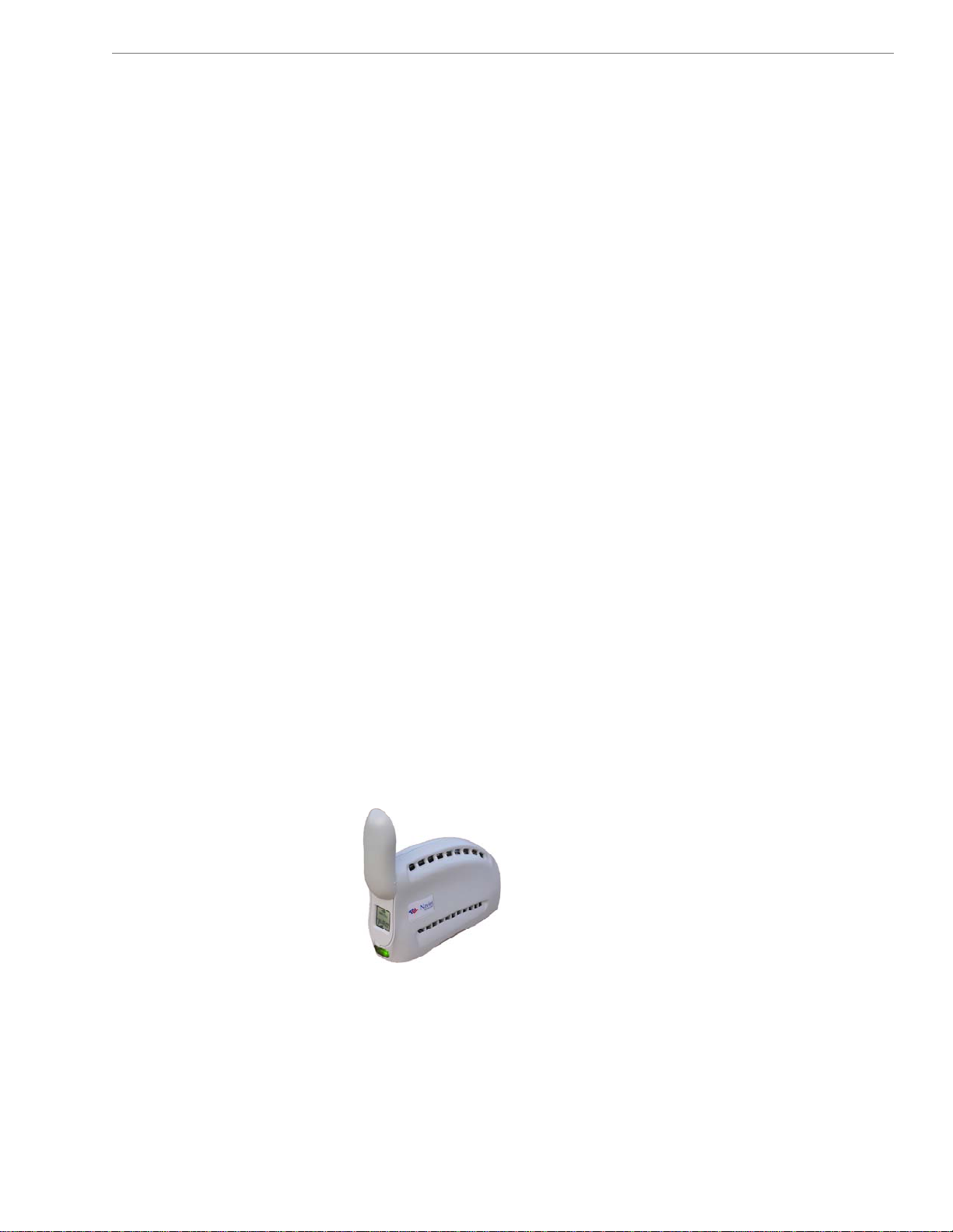
Congratulations! Your Ripwave
the LMX)
connect w
Internet access to residential and small office/home office (SOHO)
customers without requiring professional hardware installation.
The Modem also provides portable service. A computer with this
Modem can move from room-to-room, location-to-location, or
even city-to-city as long as there is coverage in the area.
This manual will guide you through the simple process of installing
the Modem and its monitoring software.
Please verify the contents of your Modem package. Your package
should contain the following:
•
• Modem AC power adapter
• Ethernet straight cable (for PC-to
• Ripwave MX Modem User Guid
• Ripwave MX Modem Quick Installation Guide
If you do not find all of these items in your package, notify the
supplier from whom you obtained it.
Your Modem comes in sever
frequency the Modem will operate in (either the 2.
2.5-2.6 GHz, 3.4 GHz, or 3.5 GHz range). The various models are
detailed on the next page.
2.3, 2.4, 2.5-2.6, 3.4 & 3.52.3, 2.4, 2.5-2.6, 3.4 & 3.5
is a user-friendly, easy-to-install device that helps you
irelessly to the Internet. It provides complete broadband
Modem
GHz LMX Modem
GHz LMX Modem
™
MX Modem (also referred to as
-Modem connection)
e (on CD)
• Navini Diagnostics Installation CD
al models. The model indicates the
3 GHz, 2.4 GHz,
8
060210_pv1.6_Ripwave-MX Modem User Guide_40-00382-00b(4.4.2)
Page 9
Navini Networks, Inc. Ripwave MX Modem User Guide
Operating
Frequencies
inimum
M
omputing
C
equirements
R
ee, also, Addendum 1)
(S
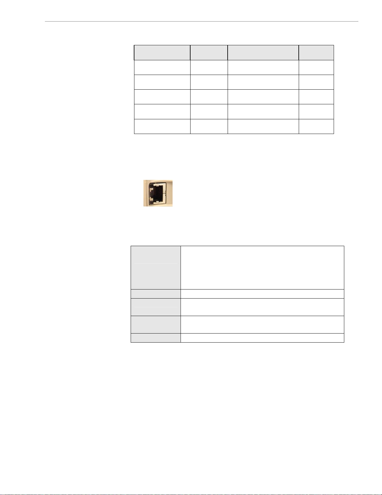
Modem Model Frequency Range Operating
Band
2.3 GHz LMX 2305-2360
LMX E
2.4 GHz LMX 2400-2483
LMX E
2.5–2.6 GHz LMX 2.5-2.6
LMX E
3.4 GHz LMX 3410-3525
LMX E
3.5 GHz LMX 3475-3600
LMX E
2.305 GHz – 2.360 GHz WCS
2.400 GHz – 2.483 GHz ISM
2.500 GHz – 2.686 GHz EBS-BRS
3.410 GHz – 3.525 GHz WLL
3.475 GHz – 3.600 GHz WLL
The “E” in the model name stands for Ethernet. Your computer
ould have an Ethernet port for connecting the Modem. An
sh
Ethernet connection will function with any Win32
System (Windows
®
98 or later)
.
®
Operating
The following table lists the minimum requirements
should meet before connecting to the Ri
pwave MX Modem.
your computer
Operating
System1:
Any Win32 Operating System (OS) - Windows NT,
Windows 982, Windo
Windows ME
2
, Windows XP
ws 98SE , Windows 2000,
2
3
, or later version.
General Information:
Ensure that the pc network port is enabled.
CPU:
RAM:
Pentium level or higher
32 MB or the Operating System minimum,
whichever is greater
Hard Drive:
Monitor:
1
Note: To upgrade your Operati
software, you must first uninstall
Otherwise, Navini Dia
Guide.
2
Note: The Modem must be left
any Windows 98 or ME platform
the monitor. In the event that hap
the PC.
3
Windows XP must be Service Pack Level 1 or higher.
Note:
4
Navini Diagnostics software is supported on Win98, Win98SE, Win2000,
Note:
inME, WinXP or higher, Mac X (also called Mac10) or higher, or Red Hat
W
inux 8.0 or higher. Mac users must have the Snuffit extraction software.
L
50 MB free disk space for the Navini Diagnostics
onitoring software
m
4
256 colors, 800 x 600 resolution
ng System after loading the Navini Diagnostics
Navini Diagnostics prior to upgrading the OS.
gnostics will not work. See
powered ON whenever you shut down or restart
s. If the Modem is off, a blue screen appears on
pens you will most likely have to power cycle
Uninstall instructions in this
9
060210_pv1.6_Ripwave-MX Modem User Guide_40-00382-00b(4.4.2)
Page 10
Navini Networks, Inc. Ripwave MX Modem User Guide Navini Networks, Inc. Ripwave MX Modem User Guide
hysical
P
Characteristics
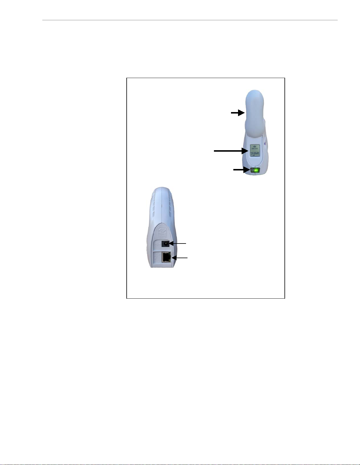
The following figure shows the physical characteristics of the
Modem.
LMX Modems (2.3, 2.4, 2.5-2.6, 3.4, & 3.5 GHz)
Antenna
Antenna
Antenna
Liquid Crystal Display
Liquid Crystal Display
Liquid Crystal Display
On/Off Button
On/Off Button
On/Off Button
Front
Front
Front
Power Adapter Connection
Power Adapter Connection
Power Adapter Connection
Ethernet Cable Connection
Ethernet Cable Connection
Ethernet Cable Connection
Back
Back
Back
10
10
060210_pv1.6_Ripwave-MX Modem User Guide_40-00382-00b(4.4.2)
060210_pv1.6_Ripwave-MX Modem User Guide_40-00382-00b(4.4.2)
Page 11
Navini Networks, Inc. Ripwave MX Modem User Guide
The f instruc plain ur M
Installing
the
Modem
ee, also, Addendum 1)
(S
ollowing tions ex how to install yo odem.
Please read all instructions before installing the Modem. Also, turn
o er an em M .
ff the comput d the Mod before installing the odem
Note: e Mo ld i
interference with other equipment when transm
Australian requirem te th ac
o ny p er e 20
r more from a erson or us . If the antenna is clos r than
c er, A afety conditions are violated.
m from the us ustralian s
Step Action Illustration
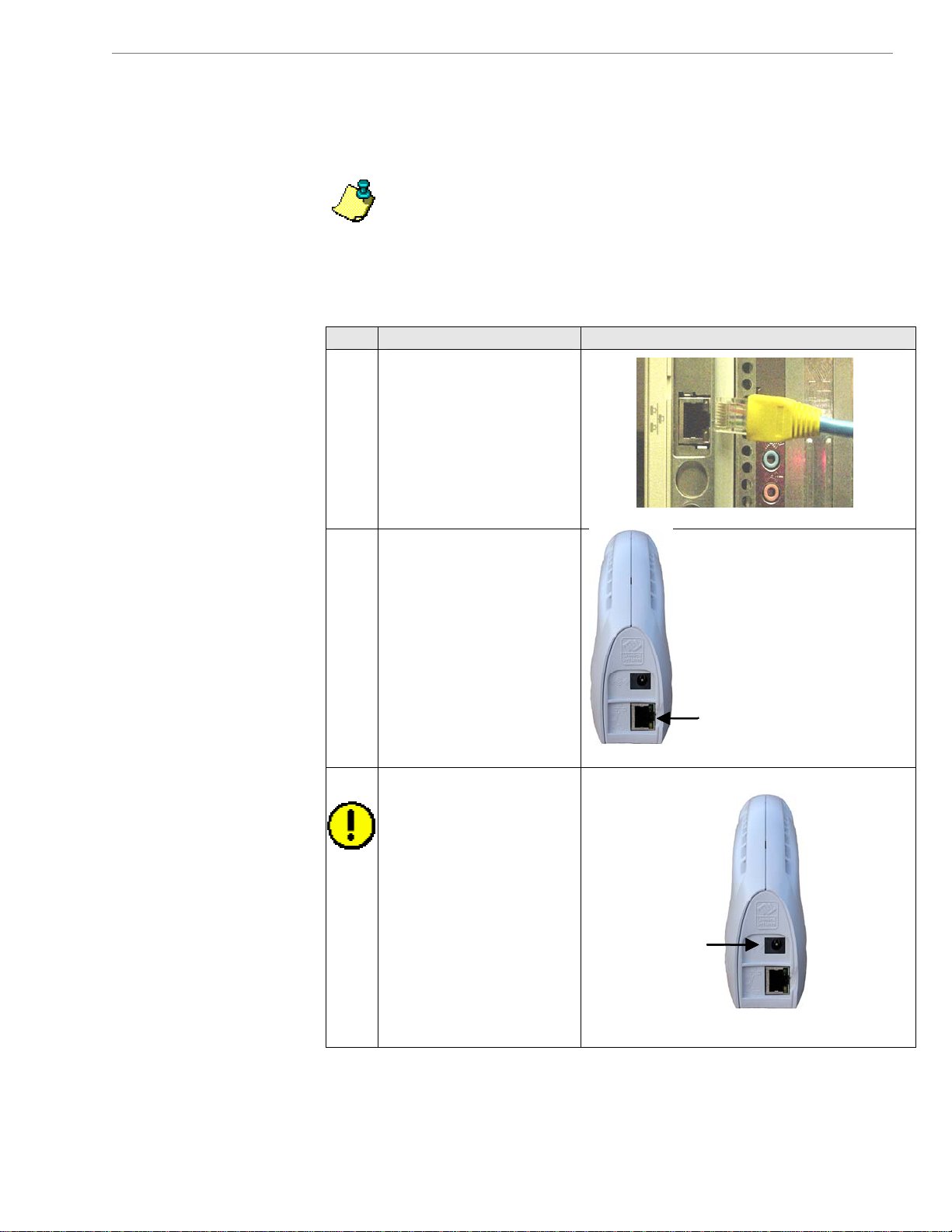
1. Connect the Ethernet
2. Connect the other end of
3. Connect t
Th dem shou be positioned to minim ze
itting. Also,
e Modem should be plents sta ed 30 cm
cable to the Ethernet
port on the computer.
the Ethernet cable to the
Modem.
he AC power
adapter the Modem.
Plug the o
pow apter into a
110/220
outlet.
CAUTION! Use only
the AC power adapter
supplied with the
Modem. Using any other
adapter can damage the
Modem.
to
ther end of the
er ad
VAC 60/50 Hz
Power adapter
Power adapter
connection
connection
Ethernet cable
Ethernet cable
connection
connection
11
060210_pv1.6_Ripwave-MX Modem User Guide_40-00382-00b(4.4.2)
Page 12
Navini Networks, Inc. Ripwave MX Modem User Guide
continued
odem, Installing the M
Step Action Illustration
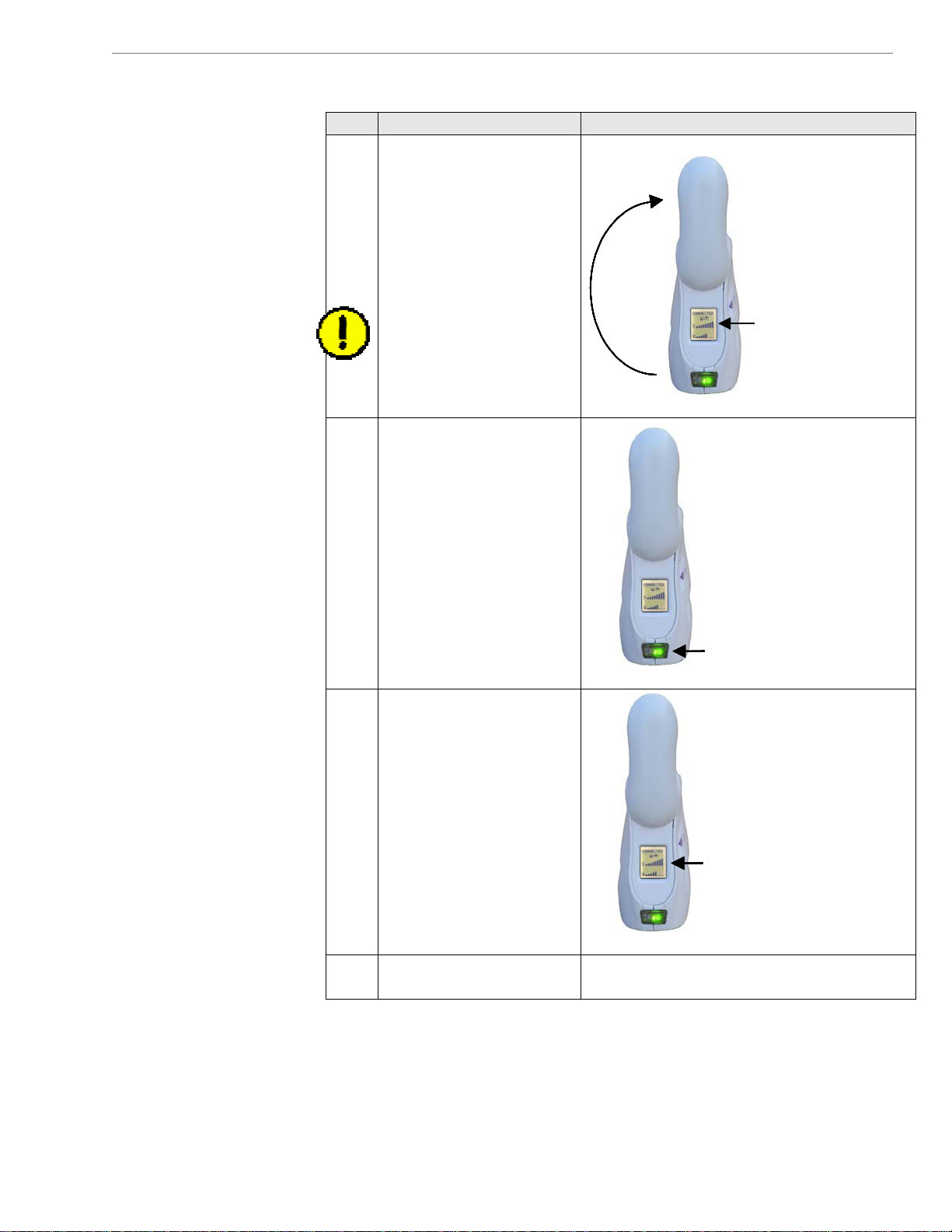
4. Rotate the Modem’s
antenna clockwise 180°
Antenna
Antenna
to the UP position.
When the antenna is in
the UP position, the
Modem’s liquid crystal
display (LCD) can be
seen.
Liquid Crystal
Liquid Crystal
CAUTION! Rotating
Liquid Crystal
Display
Display
Display
the antenna up in any
other direction can
damage the Modem.
5. Turn the Modem ON by
pushing the On/Off
button in.
On/Off ButtonOn/Off ButtonOn/Off Button
6. If the LCD turns on,
proceed to Step 7. If the
LCD does not turn on,
there is a problem with
the Modem or the AC
power adapter. Check all
cables for proper
connection. If there is
still a problem, contact
Liquid Crystal
Liquid Crystal
Display (LCD)
Display (LCD)
the supplier who gave
you the package.
7. Turn your computer on
and log in.
12
060210_pv1.6_Ripwave-MX Modem User Guide_40-00382-00b(4.4.2)
Page 13
Navini Networks, Inc. Ripwave MX Modem User Guide
Accessing the
Internet
Troubleshooting
he Liquid Crystal
T
isplay (LCD)
D
Now that your Modem is installed and both the Modem and
computer are powered on, you should be able to access the Internet
(that is, assuming you have signed up with a Service Provider).
ccess the Internet, open the web browser that is installed on your
a
computer.
If you are experiencing difficulties with your Internet connection
after installation, please review the
equirements
R
e lso review the ins dures and ensure
requir ments. A tallation proce
the roperly.
all steps were completed p
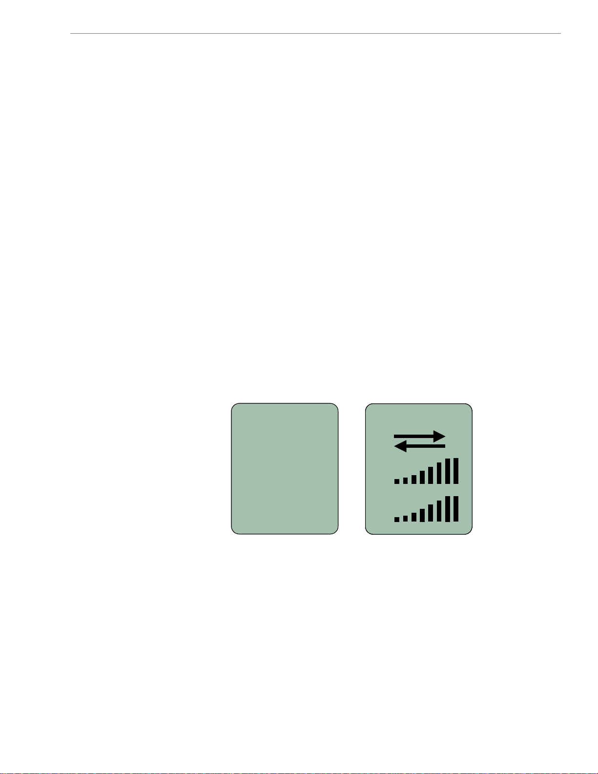
If you are still experiencing difficulties, look at the Modem’s LCD.
The LCD is a text-based display that provides valuable information
about the Modem’s operation. When you use the LCD in
conjunction with the Navini Diagnostics (NavDiag) monitoring
twa gnal issues, network c nnections,
sof
and
Below is a picture of the Modem’s LCD and the various
indications you will see on the LCD.
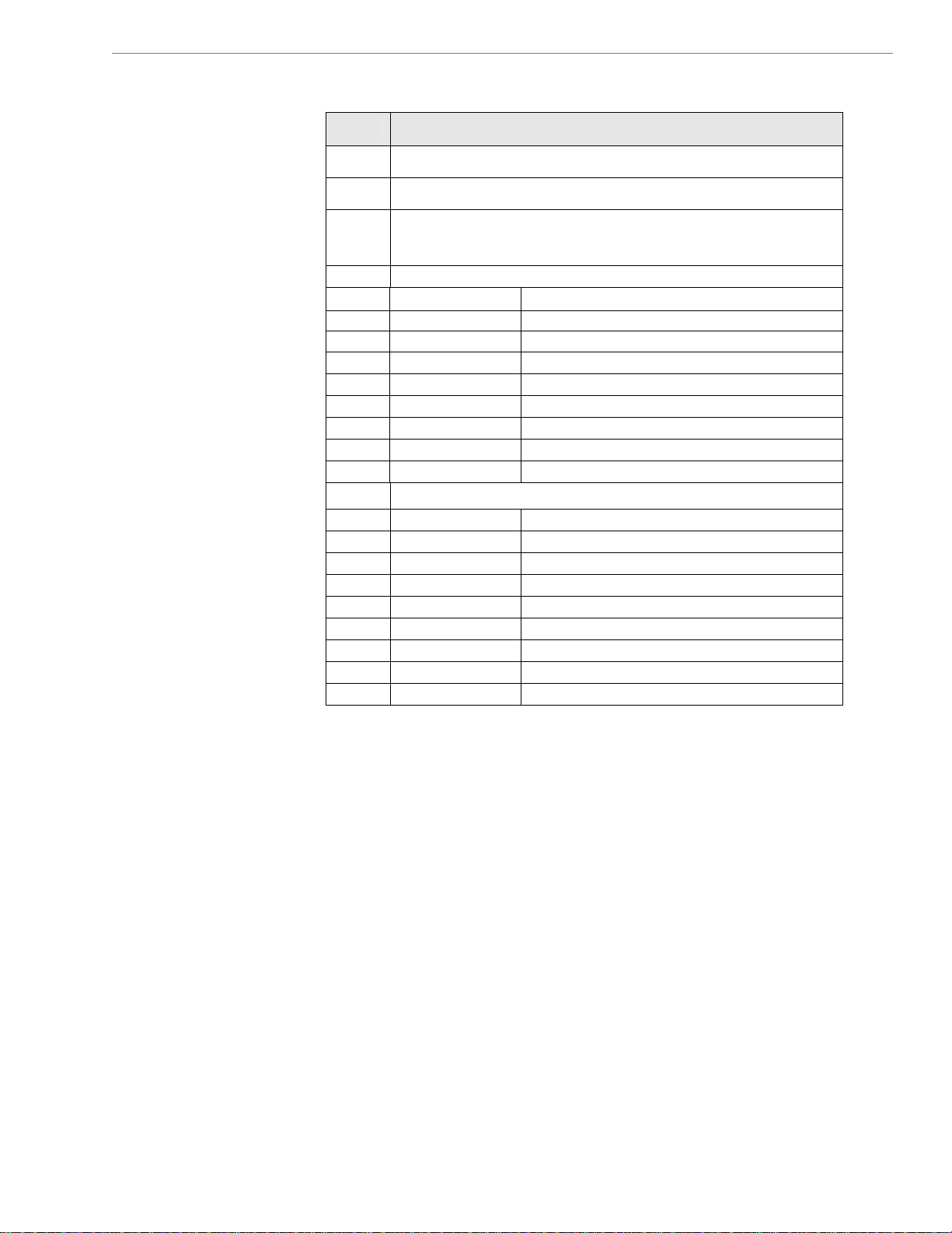
The following table defines the indicators that appear on the LCD.
re, you can troubleshoot si
po
wer problems.
1
1
SEARCHING
SEARCHINGSEARCHING
and Addendum 1. Ensure your computer meets those
Minimum Computing
2
2
2
CONNECTED
CONNECTED
CONNECTED
CONNECTED
3
3
3
4
4
4
S
SS
S
SS
5
5
5
Q
Q
Q
Q
o
To
13
060210_pv1.6_Ripwave-MX Modem User Guide_40-00382-00b(4.4.2)
Page 14
Navini Networks, Inc. Ripwave MX Modem User Guide
The LCD, continued
LCD Indicators:
1
2
Activity Indicator:
3
4 ator (SSI) S: Signal Strength Indic
S < 100 dBm 0 bars
1 bar -99 < S ≤ -100 dBm
S ≤ -99 dBm 2 bars -96 <
< S ≤ -95 dBm 3 bars -92
≤ -91 dBm 4 bars -88 < S
< S ≤ -87 dBm 5 bars -84
6 bars -80 < S ≤ -83 dBm
6 < S ≤ -79 dBm 7 bars -7
-70 < S ≤ -75 dBm 8 bars
5 Q: Signal-to-Noise Ratio (SNR)
0 bars Q < 10 dB
1 bar 10 < Q ≤ -12 dB
2 bars 13 < Q ≤ -14 dB
3 bars 15 < Q ≤ -16 dB
4 bars 17 < Q ≤ -18 dB
5 bars 19 < Q ≤ -20 dB
6 bars 21 < Q ≤ -22 dB
7 bars 23 < Q ≤ -24 dB
8 bars Q ≥ 24 dB
Both arrows flashing: There is traffic activity.
Blank: There is no traffi
Modem has locked-on to a BTS. CONNECTED: The
The Modem is syncing with a BTS. SEARCHING: Blinking flash:
c activity
14
060210_pv1.6_Ripwave-MX Modem User Guide_40-00382-00b(4.4.2)
Page 15
Navini Networks, Inc. Ripwave MX Modem User Guide
Installing Navi
Diagnosti
NavDiag)
(
cs
The NavDiag software assists you in solving connection prob
ni
and provides other valuable information. This software is provided
on a CD that came in your Modem package. This section explains
how to install this software.
Note: To install NavDiag on a Windows 2000, you must have
dministrative privileges. To check your account privileges, open
a
your Control Panel. Double-click on the Users and Passwords
symbol. You should see Administrator under the Users tab
Note:
from a laptop with Windows 2000. If yo
r ME operating system, the screens you see may vary from the
o
screens shown in the instructions.
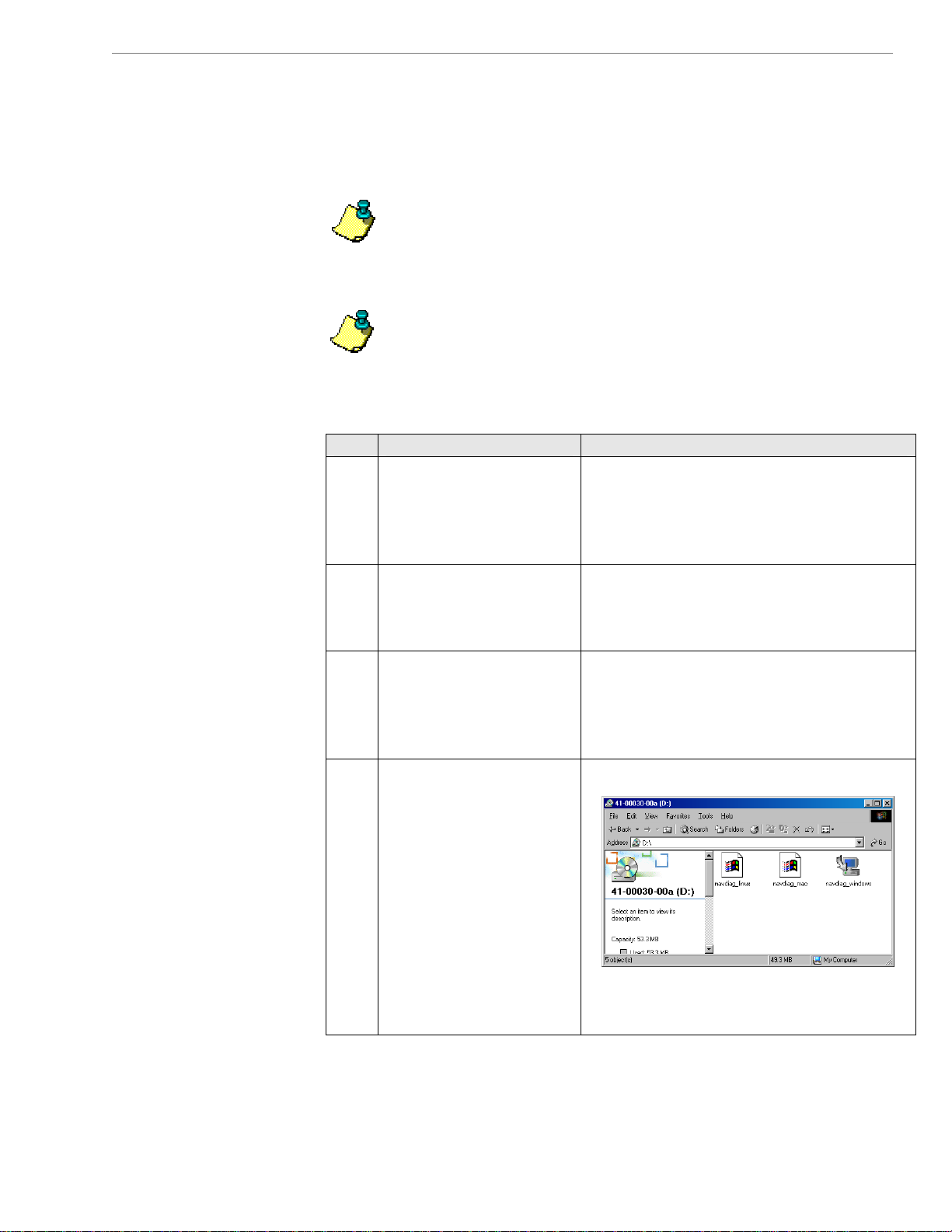
Step Action Illustration
1. Before installing the
2. Insert the Navini
3. Open the CD by clicking
4. Double-click on the icon
The screenshots shown in these instructions were take
u have a Windows 98, XP,
NavDiag software, shut
down all programs,
including anti-virus
software progra ms.
Diagnostics Installation
CD into the CD-ROM
drive.
on the
icon. Double-click on
the folder named
Navini_Diagnostics.
for the file
navdiag_windows.exe*.
This will automatically
start the installation of
the Navini Diagnostics.
*If your PC is running Mac
or Linux software, you will
need the navdiag_mac.sit or
navdiag_linux.bin file. Mac
users will need the Snuffit
extraction software.
My Computer
Example:
lems
.
n
15
060210_pv1.6_Ripwave-MX Modem User Guide_40-00382-00b(4.4.2)
Page 16
Navini Networks, Inc. Ripwave MX Modem User Guide
Installing NavDiag,
ontinued
c
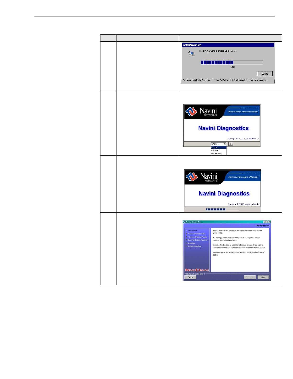
Step Action Illustration
5. The InstallAnywhere
w
indow appears. The
p
rogress bar indicates
that InstallAnywhere has
in
itialized.
6. T vini Diagno
he Na stics
Language screen
Windows 2000 Screen
appears*. Select a
language and click
OK
to continue.
7. The progress bar
in es the files b
Windows 2000 Screen
installed.
8. T ini Diagno
he Nav stics
Windows 2000 Screen
Introduction screen
appears. Click
Next to
continue.
dicat eing
16
060210_pv1.6_Ripwave-MX Modem User Guide_40-00382-00b(4.4.2)
Page 17
Navini Networks, Inc. Ripwave MX Modem User Guide
Installing NavDiag,
continued
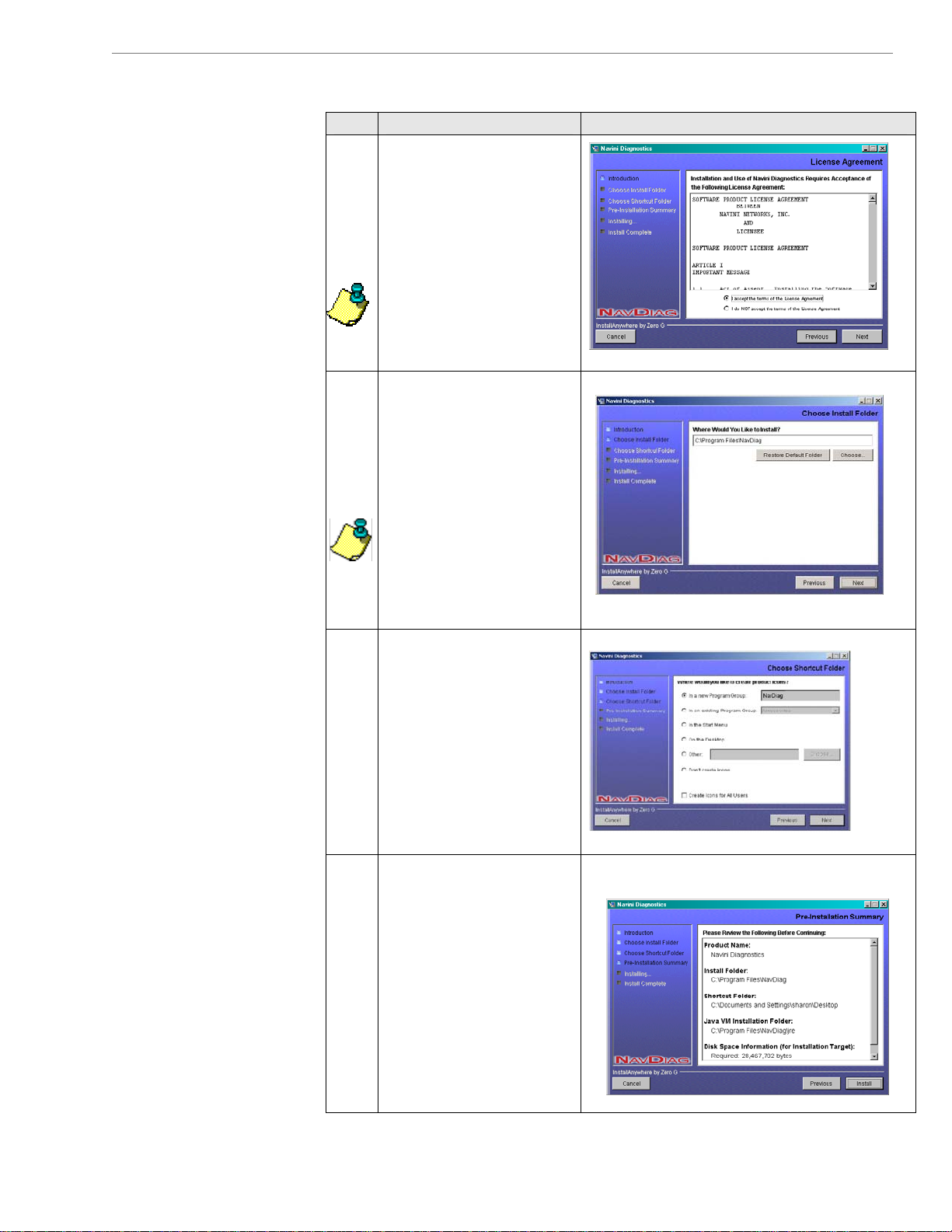
Step Action Illustration
9.
The License Agreement
screen appears. Read the
Licensing Agreement.
Select the
option, and click
I Accept
Next to
continue.
Note: If the License
Agreement is
not
accepted, you cannot
install the software.
10. The Choose Install
Windows 2000 Scree
Folder screen appears.
Enter the name of the
folder w
here you wish to
install the software.
Click
Next to continue.
Note: The default
installation folder
provided by the so
ftware
is shown in the
illustration.
11. oose Shortcut
The Ch
Windows 2000 Screen
Folder screen appears.
Select the default, In a
new Program Group,
and click
Next to
continue.
12.
The Pre-Installation
ummary screen S
Windows 2000 Screen
appears. Review the
contents for accuracy.
Click
Install to
continue.
or your installatiF
puter, this screen
com
y have different
ma
rmation than what is
info
on and
shown in the illustration.
n
17
060210_pv1.6_Ripwave-MX Modem User Guide_40-00382-00b(4.4.2)
Page 18
Navini Networks, Inc. Ripwave MX Modem User Guide
Installing NavDiag,
continued
Troubleshooting
sing Navini
U
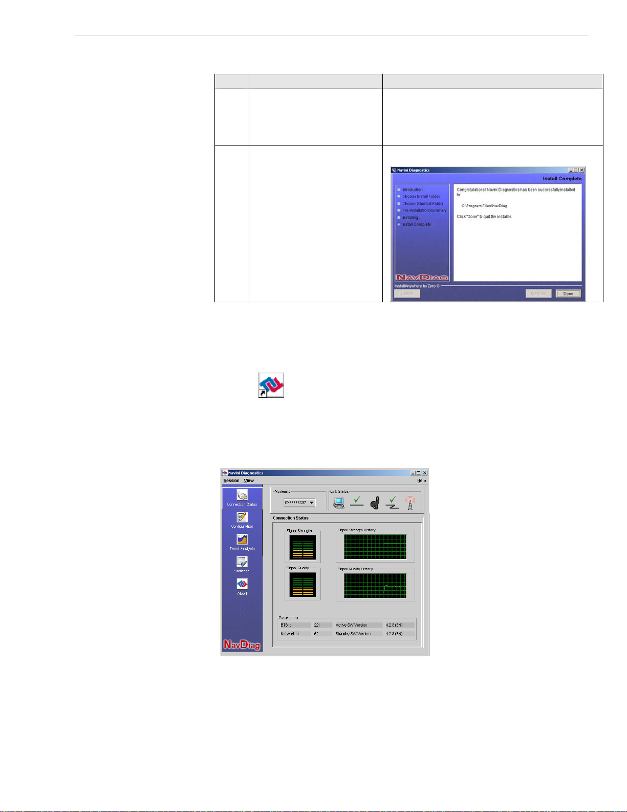
Step Action Illustration
13. The Installing screen
displays as the
application files are
loaded.
14. ll Complete
screen, click
close the window.
ope nostics software application, d uble-click
To onn the Navini Diag
the n your desk
Navini Diagnostics icon o
Done to
Windows 2000 Screen
o
top.
At the Insta
iagnostics
D
NavDiag)
(
Navini Diagnostics.lnk
The Connection Status screen opens and displays data if the
Modem is in session. The screen refreshes live data every second.
The follow
tatus screen.
S
ing sections describe the various parts of the Connection
18
060210_pv1.6_Ripwave-MX Modem User Guide_40-00382-00b(4.4.2)
Page 19
Navini Networks, Inc. Ripwave MX Modem User Guide
The Icons
The Signal
trength and
S
ignal Quality Bars
S
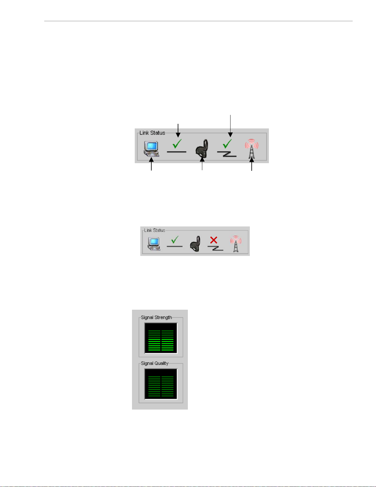
The icons that a ight side of th
PC the PC and the Modem, the
the , the connection between
Modem the Modem and the Base Station,
and the Base Station to which the Modem is communicating.
Check ections indicate working connections.
An “X” is positioned over the corresponding icon indicates the
connection between the PC and the Modem or between the Modem
and the Base Station is interrupted.
Signal Strength and Signal Quality are dynamic bar areas that
indicate how well your Modem is receiving signals from the Base
Station
, the connection between
marks over the conn
Conne
Conne
ction between
ction between
P
C & Modem
P
C & Modem
P
C
P
C
.
ppear on the top r e screen represent
Connection between
Connection between
m & Base Station
Mode
m & Base Station
Mode
Base Station
Modem
Modem
Base Station
19
060210_pv1.6_Ripwave-MX Modem User Guide_40-00382-00b(4.4.2)
Page 20
Navini Networks, Inc. Ripwave MX Modem User Guide Navini Networks, Inc. Ripwave MX Modem User Guide
articular, the Signal Strength bar area graphically represents the
The Si
Signal Quality Bars,
continued
gnal Strength and
How to Increase
the Strength and
Quality of the
Signal
The History Graphs
In p
strength of the synchronization signal your Modem is receiving
from BTS. The strength of the signal is represented by a group of
colored bars. The higher the pile of bars goes, the stronger the
signal is. The color of the bars also gives an indication of the
strength of the signal. Green lines indicate an excellent signal.
Orange lines indicate a good signal while red lines indicate a weak
signal.
The Signal Quality bar area graphically represents the Signal-toNoise Ratio (SNR) received by your Modem. Again, the quality of
the signal is represented by a group of colored bars. The higher the
pile of bars goes, the better the SNR of the signal. The color of the
bars also gives an indication of the quality of the signal. Green
lines indicate an excellent signal or an SNR greater than 21.
Orange lines indicate a good signal or an SNR greater than or equal
to 13 but less than or equal to 21. Red lines indicate a weak signal
or an SNR less than 13.
To increase the strength and quality of the signal, change the
location of your Modem. Try moving it closer to a window, to a
higher location, away from other wireless devices (microwave
ovens, cordless phones), and away from metal objects (shelves, file
cabinets). As you reposition your Modem, watch the Signal
Strength and Signal Quality bars on the NavDiag screen. Place
your Modem in the location where you receive the most green
signal strength and quality bars.
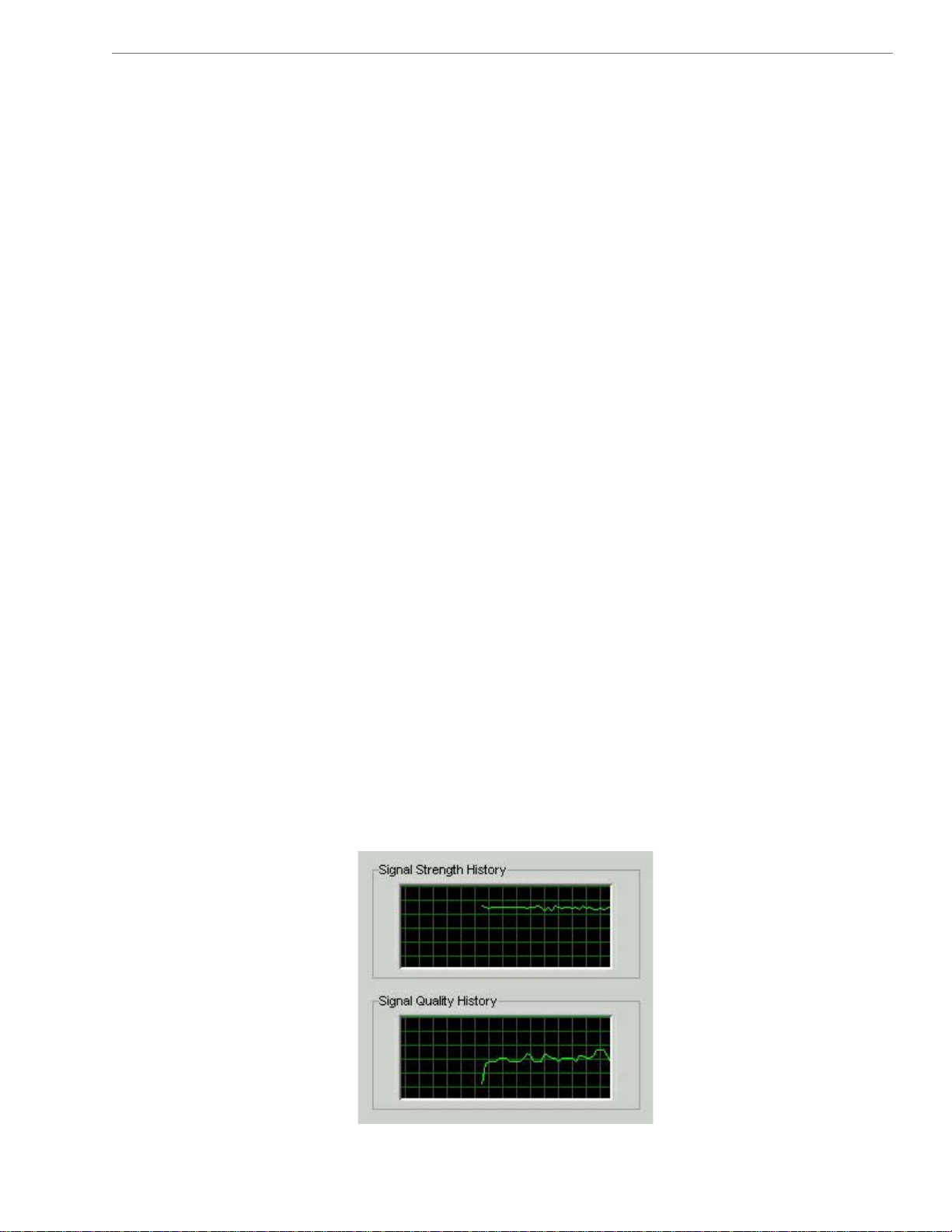
The History graphs plot the change in signal strength and signal
quality over time. The graphs cover the last minute and are updated
every second. Read the graphs from right to left. The right side of
the graph represents the most recent status of your Modem.
20
20
060210_pv1.6_Ripwave-MX Modem User Guide_40-00382-00b(4.4.2)
060210_pv1.6_Ripwave-MX Modem User Guide_40-00382-00b(4.4.2)
Page 21
Navini Networks, Inc. Ripwave MX Modem User Guide
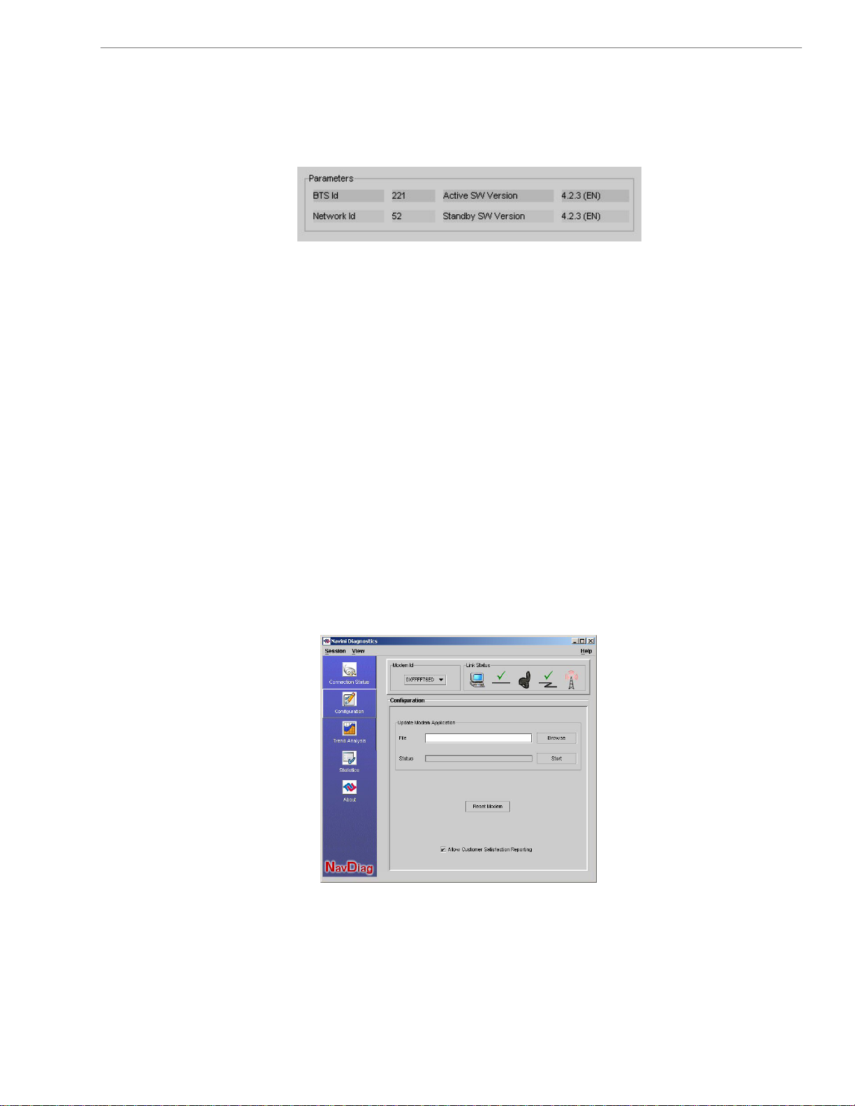
f the Connection S are four parameters.
The Parameter
s
The Screen Option
Buttons
he Configuration
T
creen
S
At the bottom o tatus screen,
e , Network ID, Active SW ersion,
Thes parameters are BTS ID
and St on.
The BTS ID indicates the BTS to which the Modem is currently
synchronized. The Network ID indicates the network in which the
Modem is operating. Active SW Version and Standby SW Version
indicate the version number of the software currently loaded in the
“active side” and “standby side” of the Modem’s flash memory.
The two letters in parenthesis following the release number
indicate the type of software load: JD indicates Joint Detection,
while EN indicates Enhanced Nulling.
On the left-hand side of the screen, there are five screen option
buttons: Connection Status, Configuration, Trend
S
capabilities.
The Configuration screen enables you to update your Modem
software if your Service Provider directs you to do so. To access
the Configuration screen, press the Configuration button.
If
w
andby SW Versi
tatistics, and About. Each of these screens provides unique
you must update your Modem’s software, your Service Provider
ill provide you with instructions regarding what to do.
V
Analysis,
’s
21
060210_pv1.6_Ripwave-MX Modem User Guide_40-00382-00b(4.4.2)
Page 22
Navini Networks, Inc. Ripwave MX Modem User Guide
The Configurati
ontinued c
he Trend Analysis
T
creen
S
on Screen,
At the bottom of the screen is an Allow Customer Satisfaction
Reporting box. This box gives you control over whether you
Service Provider is allowed to monitor your Modem’s performance
using the remote CPE Logging function and store the log files
created by the CPE Logging function on your computer. By
default, this box is checked which means the Service Provider can
monitor your Modem.
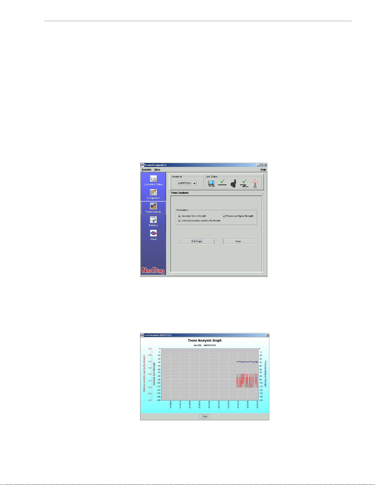
The Trend Analysis screen lets you view how some Modem
parameters evolve over time. With this screen, you can select up to
three parameters to plot. To view the Trend Analysis screen, press
the Trend Analysis button.
By pressing the Plot Graph button, the following screen appears.
This screen displays the value of the selected parameters over the
last five m
scrolls from right to left.
inutes and updates once every second. The graphic
r
22
060210_pv1.6_Ripwave-MX Modem User Guide_40-00382-00b(4.4.2)
Page 23
Navini Networks, Inc. Ripwave MX Modem User Guide
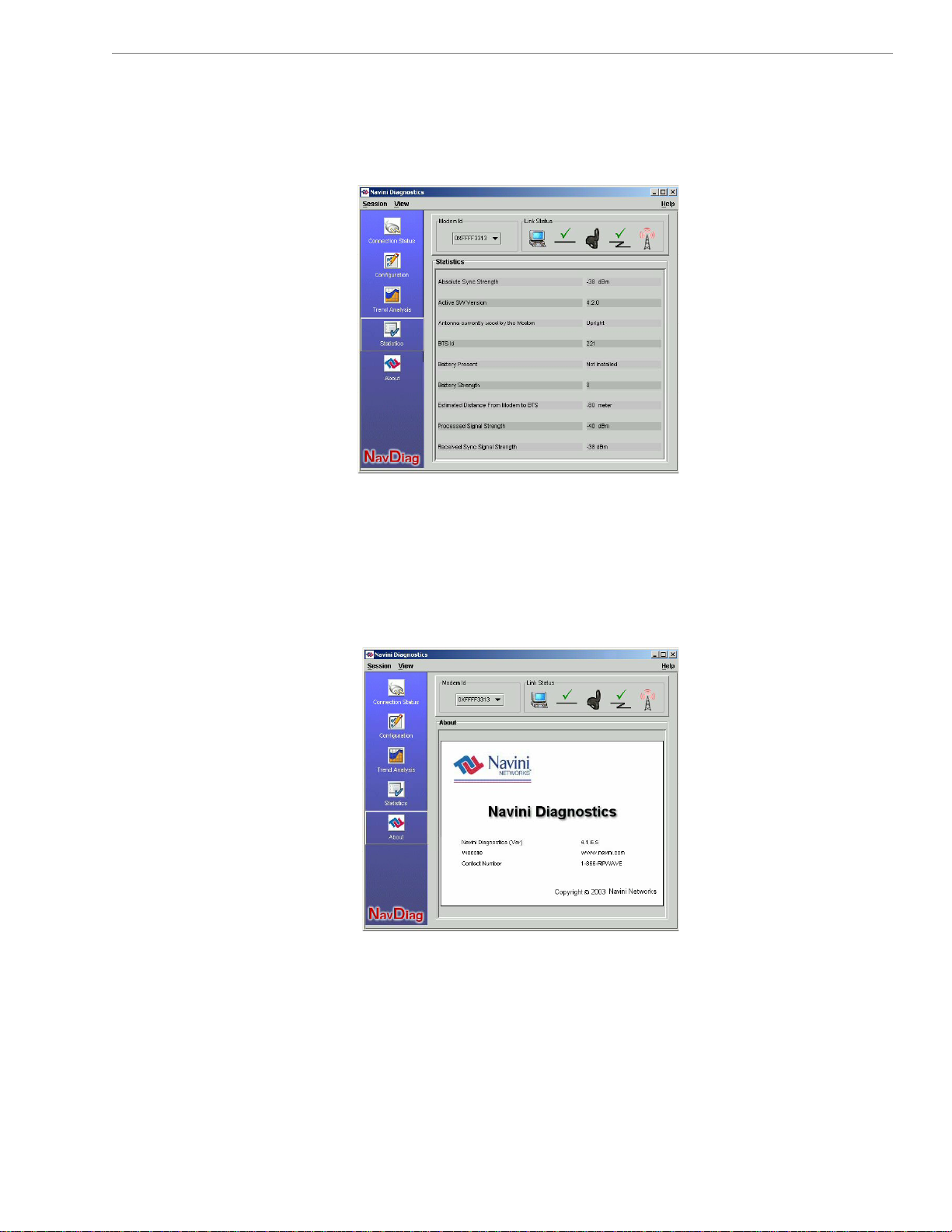
he statistics screen lets you view the current value of selected
The Statistics
Screen
he About Screen
T
The Help Button
T
parameters. These values are updated as they change over time. To
view the Statistics screen, press the Statistics button.
he About screen provides vital information such as the version of
T
e Navini Diagnostics software currently installed on your
th
computer. It also provides a website address and telephone nu
where you can contact your Service Provider. To view the About
screen, press the About button.
Help button appears on the top right corner of all the NavDiag
A
indows. The Help button gives you two options. The first option,
w
n NavDiag, provides help text on the functionality of the
O
avDiag program. The second option, About NavDiag, is
N
quivalent to clicking on the About icon.
e
mber
23
060210_pv1.6_Ripwave-MX Modem User Guide_40-00382-00b(4.4.2)
Page 24
Navini Networks, Inc. Ripwave MX Modem User Guide
Navini Networks, Inc. Ripwave MX Modem User Guide
ninstalling
U
Navini
Diagnostics
(NavDiag)
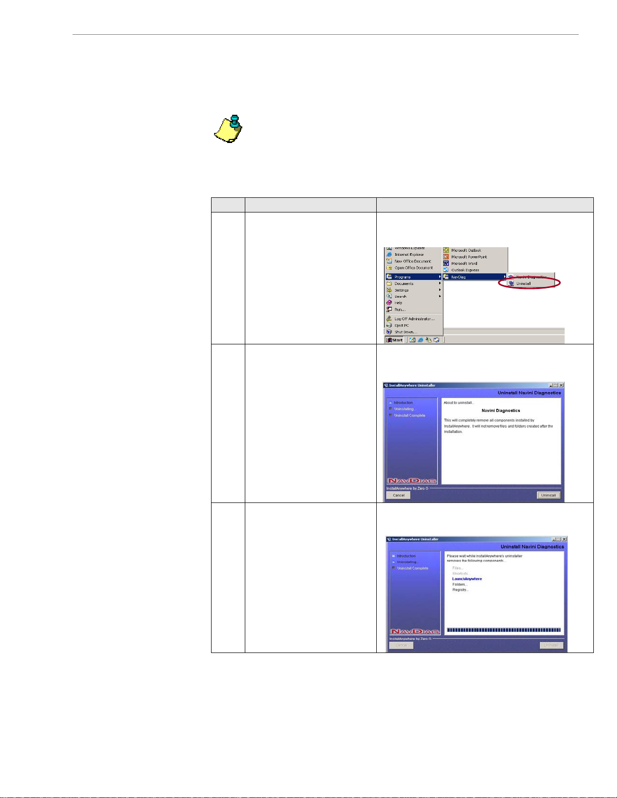
If for some reason you need to uninstall the Navini Diagnostics
software, e.g., to upgrade your Operating System software, follow
the procedure below.
Note:
taken from a laptop with Windows 2000. If you have a Windows
98, XP, or ME operating system, the screens you see may vary
from the screens shown in the instructions.
Step Action Illustration
1. On your computer
2. The Install-Anywhere
3. The screen indicates
The screen shots shown in these instructions were
screen lower left corner,
click on
Programs > NavDiag >
Uninstall.
Uninstaller screen
appears. Click
Uninstall.
when the application
files are uninstalled.
Windows 2000 Screen
Start >
Windows 2000 Screen
Windows 2000 Screen
24
24
060210_pv1.6_Rip060210_pv1.6_Ripwave-MX Modem User Guide_40-00382-00b(4.4.2)
wave-MX Modem User Guide_40-00382-00b(4.4.2)
Page 25
Navini Networks, Inc. Ripwave MX Modem User Guide
Uninstalling NavDiag,
ontinued c
ptional Battery
O
Packs
Step Action Illustration
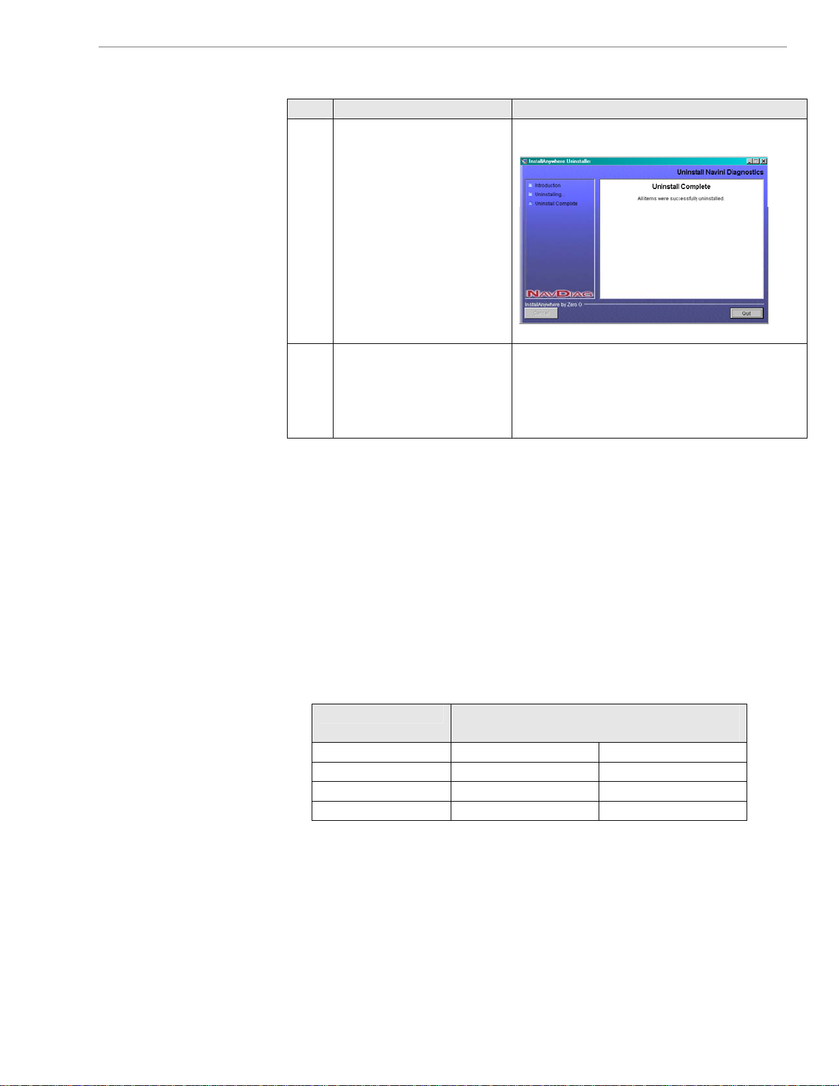
4. The Uninstall Complete
screen appears when
finished. Click on
to close the Uninstall
screen.
5. Restart the PC to
complete the uninstall
process. This ensures the
uninstall process
completes successfully.
wo optional external battery packs areT available for your Modem.
hese battery packs are the Standard External Battery Pack (S-
T
EBP) and the Heavy Duty-External Battery Pack (HD-EBP). Bo
batteries can be used with any of the LMX Modems.
The S-EBP provides 16 Watt-Hours of power while the HD-EBP
rovides 44 Wp
How long the battery packs can operate before recharging varies
As the table below shows, this time is dependent of the type of
usage you run on your Modem.
Moderate 1.2 Approximately 4
att-Hours of power.
Usage Approximate Hours of Usage Before
Standard Up to 2.5 Up to 8
Heavy Up to 1 Up to 3
Quit
Windows 2000 Screen
Recharge Required
S-EBP HD-EBP
th
.
25
060210_pv1.6_Ripwave-MX Modem User Guide_40-00382-00b(4.4.2)
Page 26
Navini Networks, Inc. Ripwave MX Modem User Guide
Connecting the
S-EBP
The Indicator Light
on the S-EBP
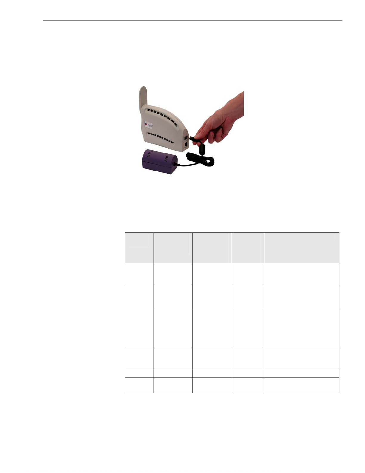
The optional battery packs are not installed inside the Modem.
Instead they are connected to the Modem. To connect the S-EBP to
your Modem, plug the battery pack’s pig-tail cord into the input
socket located on the back of the Modem.
The S-EBP has one indicator light that resides on top of the unit.
This light has four states associated with it. The states are
described below.
Battery
LED
Green Yes Not
Amber Yes Not
Off No Yes Yes Normal. Battery is
Red No Yes Yes Battery is supplying
Off No Yes No Battery is out of power.
Off No No No Battery LED is off. Status
Battery
Charger
Connected
Modem
Connected
& Switched
On
applicable
applicable
Modem
On/Off
Button is
Lit
Not
applicabl
e
Not
applicabl
e
Comments
Battery fully charged.
Battery charging.
supplying power to
Modem. No power is
wasted on the battery
LED.
power to Modem. Battery
is low. 5% charge left.
of battery is unknown.
1
26
060210_pv1.6_Ripwave-MX Modem User Guide_40-00382-00b(4.4.2)
Page 27
Navini Networks, Inc. Ripwave MX Modem User Guide
The Indicator Light on the
S-EBP, continued
Chargin
-EBP
S
g the
Note1: As with any battery, when the S-EBP is left unused
a long period of time, it tends to lose its charge. When this hap
and when the charge drops to approximately 5% of the full charge
level, the red LED comes on to indicate that the battery’s charg
level is low. After a limited duration, the internal circuitry wi
down both the LED and the battery to prevent the battery from
going into a deep-discha
store it to its normal healthy state.
re
The S-EBP needs to be recharged when the battery is connected to
a Modem and the Modem is turned on but the LED on top of the
battery remains off (indicati
ndicating the battery level is low).
(i
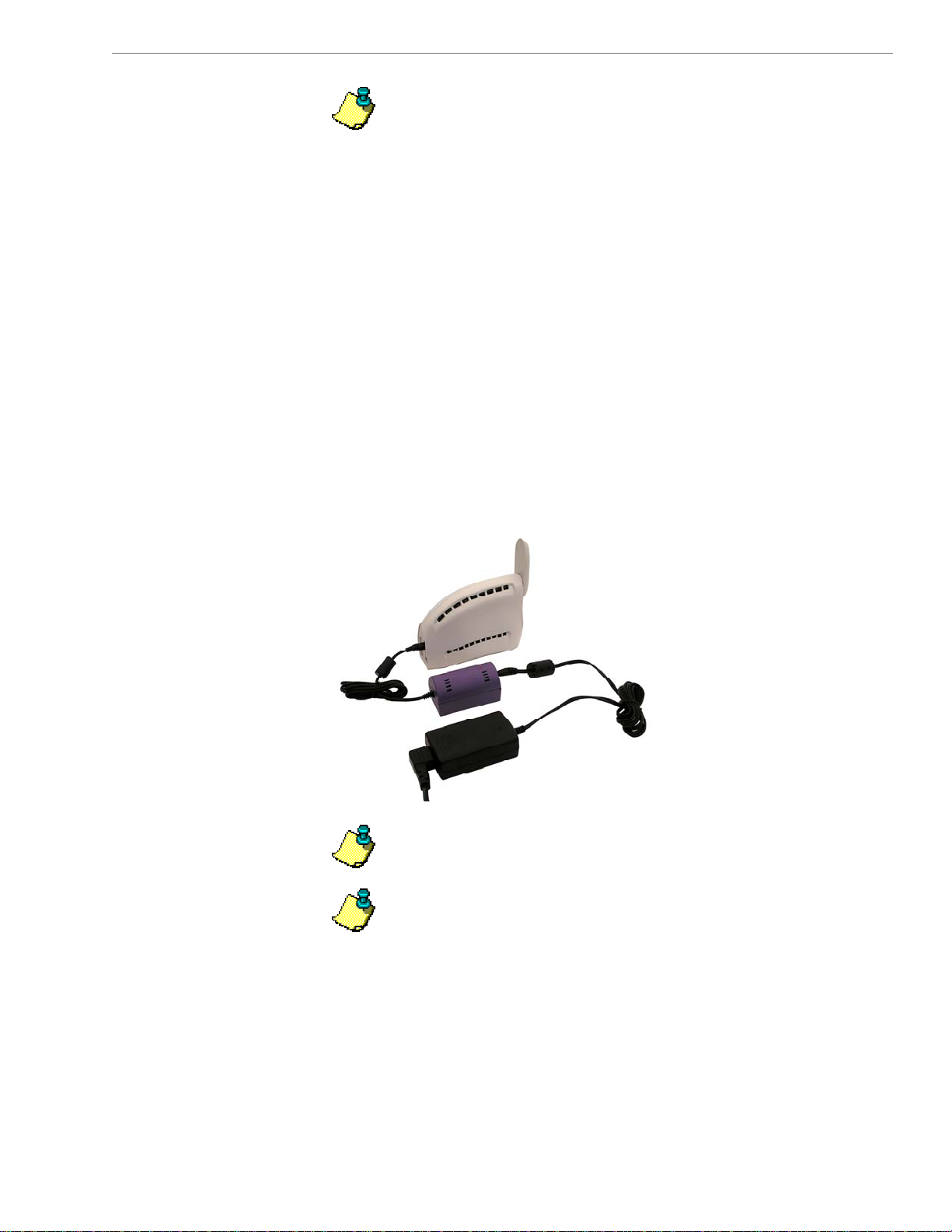
o recharge the S-EBP, use
T
e S-EBP. Using any other charger can damage the battery. To
th
harge the S-EBP, plug the 12V adapter into the 12V input socket
c
n the S-EBP.
o
Note: The battery may charge while it is connected to a
odem.
M
Note: Do not attempt to plug the 12V adapter into the Modem
s this can harm the Modem.
a
rge state. Recharging the battery will
ng the battery has no power) or is red
only the 12V charger that came with
for
pens
e
ll shut
27
060210_pv1.6_Ripwave-MX Modem User Guide_40-00382-00b(4.4.2)
Page 28
Navini Networks, Inc. Ripwave MX Modem User Guide
Connecting an
Disconnd ecting the
D-EBP
H
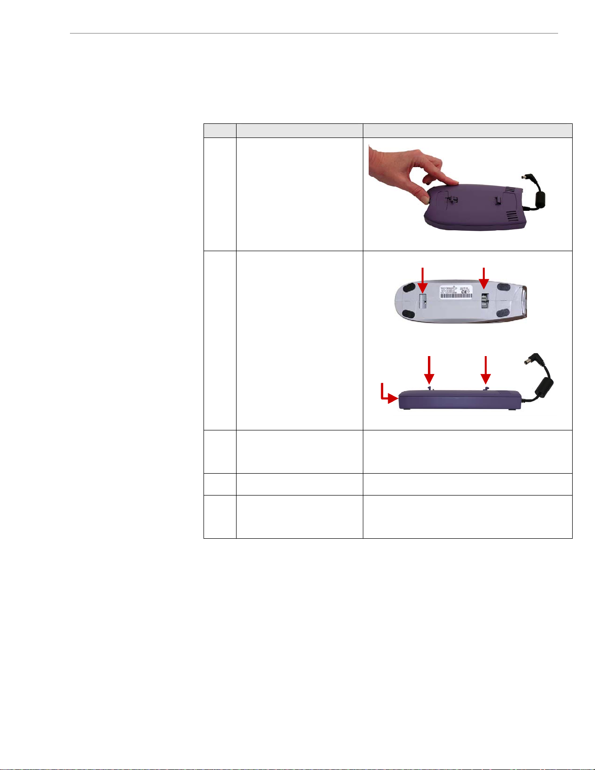
If you have a HD-EBP, the battery pack is installed in the bottom
of the Modem. To install and or remove the battery pack, follow
the steps below.
Step Action Illustration
1. Depress the front button
on the battery so that the
front prong moves in
towards the center of the
battery.
2. Place the back slot of
the Modem over the
Front slot Back slotFront slot Back slotFront slot Back slot
back prong of the
battery.
Front prong Back prong
Front prong Back prong
Front prong Back prong
Front
Front
Front
button
button
button
3. Place the front part of
the opening on the
Modem over the front
prong on the battery.
4. Release the button on
the battery.
5. Press firmly down on
the Modem so that the
Modem firmly connects
with the battery.
28
060210_pv1.6_Ripwave-MX Modem User Guide_40-00382-00b(4.4.2)
Page 29
Navini Networks, Inc. Ripwave MX Modem User Guide
Connecting and
Disconnecting the
HD-EBP, co
ntinued
he Indicator Light
T
n the HD-EBP
o
Step Action Illustration
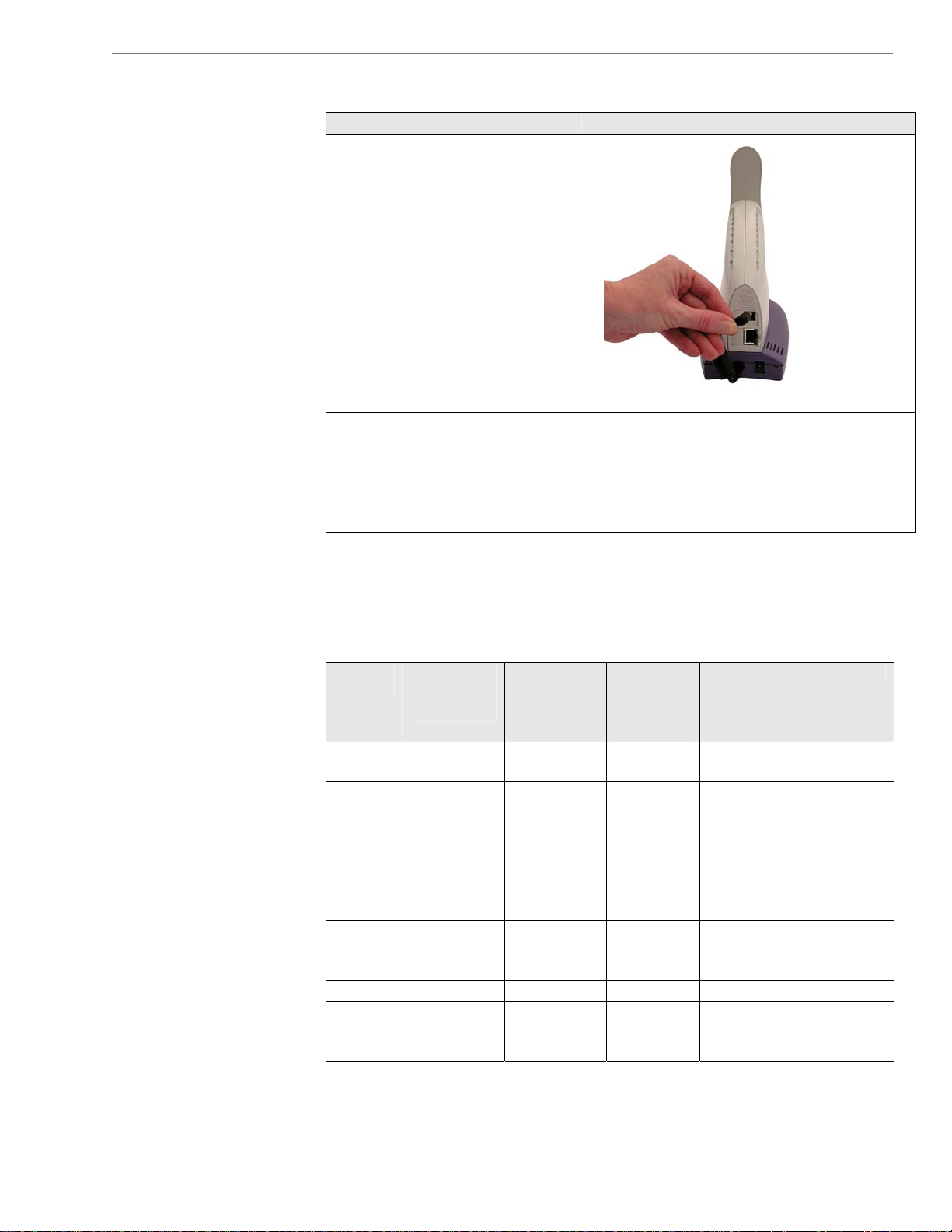
6. Plug the battery pack’s
pig-tail cord into the
power slot on the
Modem.
7. the battery
To remove
pack from the Modem
,
unplug the pig-tail cord.
Depress the front button
on the battery pack. Lift
the Modem off of the
battery pack.
The HD-EBP has one indicator light that resides on the back end of
the unit near the pig-tail cord. This light has four states associated
with it. The states are described in the following table.
Battery
LED
Green Yes Not
Amber
Off Yes Normal. Battery is
Red No Yes Yes Battery is supplying
Off No Yes No Battery is out of power.
Off No No No Battery LED is off.
Battery
Charger
Connected
No Yes
Modem
Connected
& Switched
On
applicable
applic ble
able
Modem
On/Off
Button is
Lit
Not
applicable
Not
applica
Comments
Battery fully charged.
Battery charging. Yes Not
supplying power to
Modem. No power is
wasted on the battery
LED.
power to Modem. Battery
is low. 5% charge left.
Status of battery is
unknown.
1
29
060210_pv1.6_Ripwave-MX Modem User Guide_40-00382-00b(4.4.2)
Page 30
Navini Networks, Inc. Ripwave MX Modem User Guide
Charging the
HD-EBP
are and
C
aintenance
M
The HD-EBP n ed when the b
M ur ed on but the LED on the back
to a odem and the Modem is t
of the dicating the battery has no power) or
is red (indicating the battery level is low).
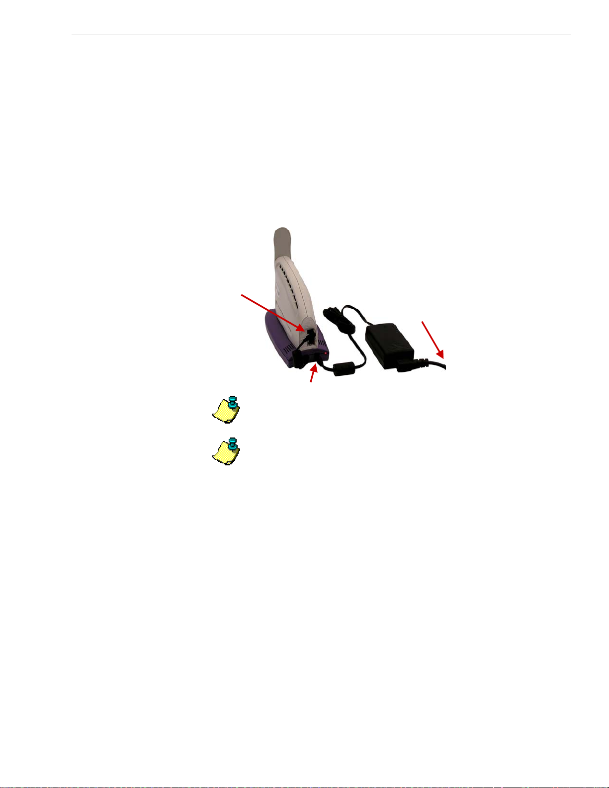
To recharge the battery pack, use
with the HD-EBP. Using any other charger can damage the battery.
To charge the HD-EBP, plug the 12V adapter into the 12V input
socket on the HD-EBP. Plug the other end of the adapter into an
electrical wall socket.
as this may harm the Modem.
Modem.
T operati
instructio
Keep the Modem free of d isture. If th ets
Keep the Modem away from high temperatures. Heat can cause
battery remains off (in
Pig-tail
Cord
Note: Do not attempt to plug the 12V adapter int
Note: The battery may charge
our Modem is designed to giveY
o ensure on, read
wet, l to dry it i .
use a towe edia
Handle the Modem gently. Dropping it or mishandling it can
cause damage to the plastic shell or the electronic circuitry.
damage to the plastic shell or the electronic circuitry.
eeds to be recharg attery is connected
n
only the 12V charger that came
Plugs into
Wall Socket
12V Input Socket
while it is connected to a
you years of trouble-free service.
the following care and maintenance
ns.
ust and mo
mm tely
e gModem
o the Modem
30
060210_pv1.6_Ripwave-MX Modem User Guide_40-00382-00b(4.4.2)
Page 31

Navini Networks, Inc. Ripwave MX Modem User Guide
Care & Maintenance,
continued
Upgrading the
odem M
Use only a mild detergent and a soft, damp cloth to clean the
Modem. Do not use any chemicals or abrasives to clean the
plastic shell.
If there is a problem with the Modem, do not attempt to repair
it yourself. Report the problem to your Service Provider.
If you are going to upgrade your Operating System after
loading the Navini monitoring software (Navini Diagnostics),
you must first uninstall the monitoring software prior to
upgrading the OS. Otherwise, the monitoring software will not
work. See
The Modem must be left powered ON whenever you shut down
or restart any Windows 98 or ME platforms. If the Modem is
off, a blue screen appears on the monitor. In the event this
happens you will mostly likely have to power cycle the PC.
There are three different ways to upgrade the software that makes
the Modem work.
Your Service Provider may perform an over-the-air (OTA)
upgr
eles he to odem.
wir
Your Service Provider m rovide wnloadable web file or
-R with soft ins yo
CD OM ware to be
upgrade the Modem hod or systems that have
ft release
a so ware
Your Service Provider m
Diagnostics Tool to upgrade your Modem ftware load. This
method is used for systems that have a softw
or greater.
The latter two methods are used only if the Mod s not
red uring the upgrade ess. T
powe on d OTA proc he OTA upgrade is
normally transparent to the user; in other words,
noticeable service interruption. The web or CD u
instr ns and ta minima ount of
with uctio kes a l am time to complete.
M Note: ol to upgrade your
odem software load, the computer connected to your Modem
Uninstall instructions in this Guide.
ade he up soft s are tra
, where t
sly from t
If you use the Navini Diagnostics To
-to-date
Base Station
ay p
. This met
p
rior to 4.0.
ay instruct you to use your Navini
ware file
your M
a do
talled on
is used f
ur PC and used to
so
are release of 4.0
em wa
there should be no
pgrade comes
nsferred
31
060210_pv1.6_Ripwave-MX Modem User Guide_40-00382-00b(4.4.2)
Page 32
Navini Networks, Inc. Ripwave MX Modem User Guide
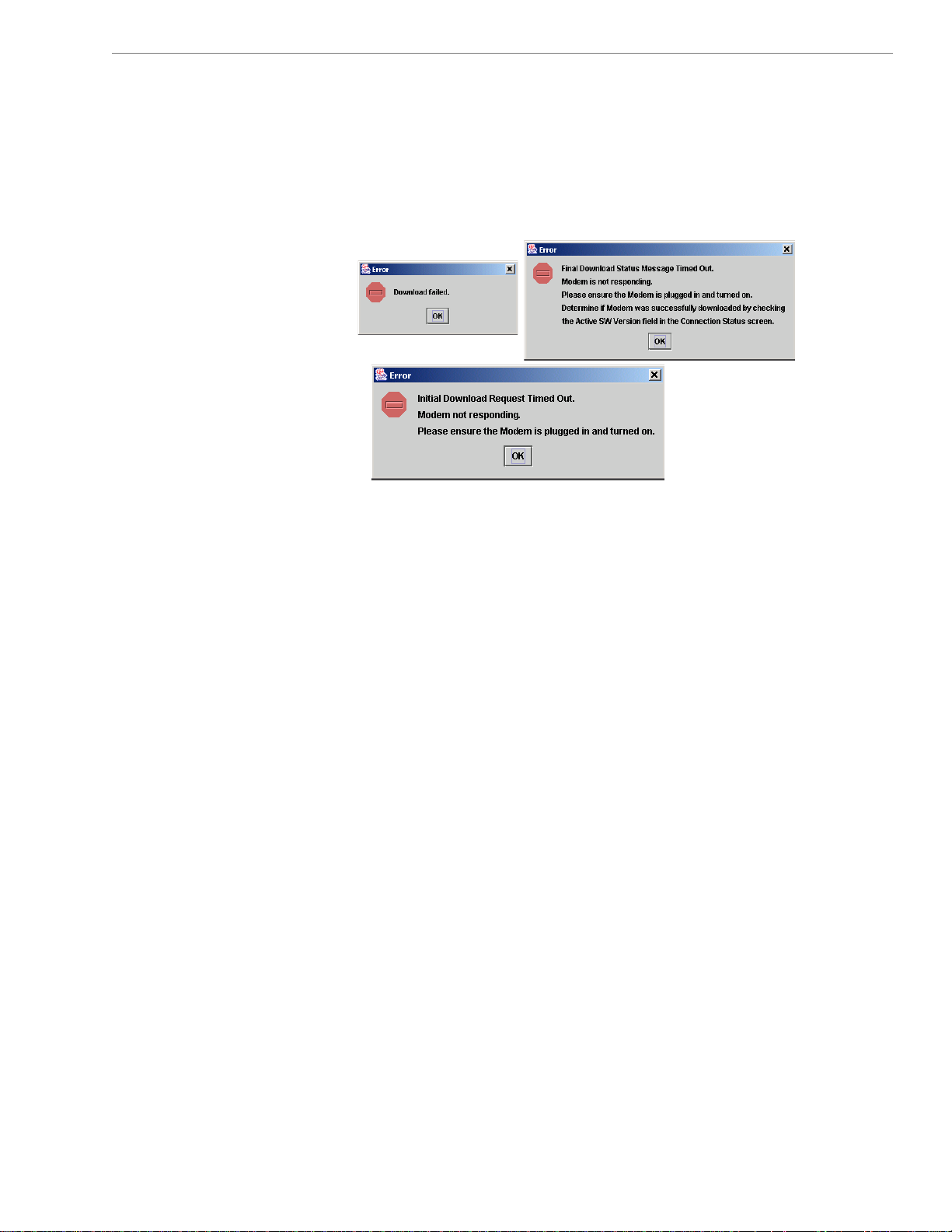
must already have an IP address. If your computer does not have an
IP address, contact your Service Provider. If you attempt to
upgrade your Modem software through the Navini Diagnostics
Tool and the computer does not have an assigned IP address, you
may see one of the following error messages:
32
060210_pv1.6_Ripwave-MX Modem User Guide_40-00382-00b(4.4.2)
Page 33
Navini Networks, Inc. Ripwave MX Modem User Guide
ADDENDUM Ripwave
1: -MX Modem - PC Troubleshooting
™
- For Use With All a d ostics Software -
Ripw ve-MX LMX Modems an
Navini Diagn
C Operating Systems
P
rior to installing the Navini Diagno k to insure that the PC Operating System
P
eets the criteria given in the table below. If these criteria are not met, unpredictable problems may
m
ccur as a result of installation. It is recommended that the user have the latest Windows
o
stalled prior to installing the Navini Diagnostics software.
in
stics software, please chec
c
updates
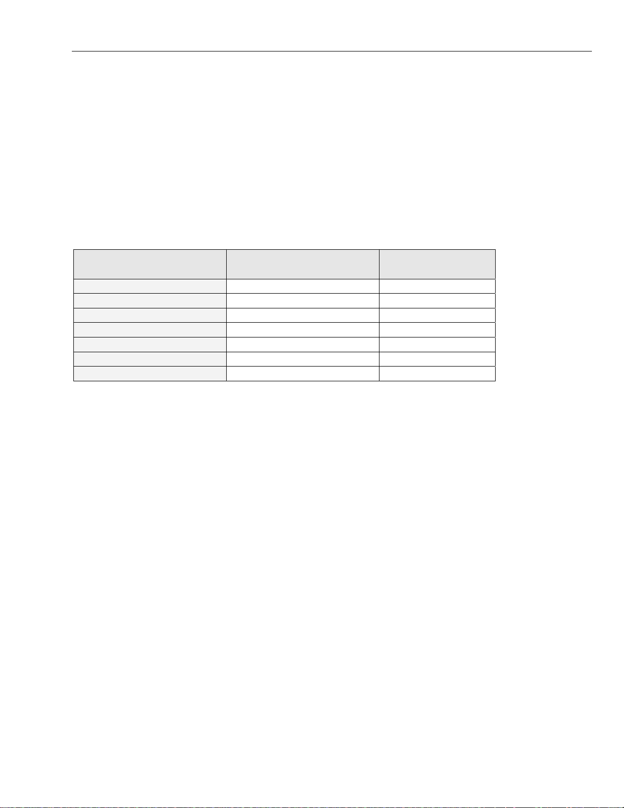
Operating System Ethernet interface Notes
Win95 Supported 1, 2
Win98 Supported 2
Win98, 2nd ed. Supported 2
WinME Supported 2
Win 2000 Supported 2
Win NT 3.0/4.0 Supported 1, 2
Win XP Supported 3
Note 1: Internet Explorer 3.0 or higher is required
ote 2: Requires Service Pack 1
N
ote 3: To load the Navini Diagnostics software, the user MUST have Administrative privileges.
N
thernet Interface
E
he Ethernet Modem may be connec rnet connection. Also, it is possible to
T ted to a PC via an Ethe
onnect multiple PC devices to a sin C configuration is transparent to the PC
sers and is analogous to a m PC mal Ethernet LAN. Check with your Service
u ulti- configuration on a nor
rovider if multiple IP addressing is required for your pa
e Ethernet Modem is that it connects to any device that has an Ethernet interface. This makes it ideal
th
r small businesses that have a mix of devices, such as Unix machines, Apple Computers, etc. IP
fo
ddresses can be assigned to the dev CP server, or as Fixed IP assignments, or
a ices dynamically via a DH
oint-to-Point Protocol Over Etherne
gle Modem. The multi-Pc
rticular configuration. The distinct advantage of P
t (PPPoE). P
ultiple Interface Environments
M
hen a PC has an internal interface (for example, a Wireless Ethernet interface) in addition to the LMX
W
odem, you should do the following:
M
If the wireless connection is not required, disable the internal wireless connection
•
If the built-in wireless connection is required for local networking and wireline Ethernet is used via
•
the LMX Modem for Internet connection, change the interface metric configuration so that the
wireline interface’s default gateway is used. (See your Operating System’s User Guide.)
33
060210_pv1.6_Ripwave-MX Modem User Guide_40-00382-00b(4.4.2)
3333
Page 34
Navini Networks, Inc. Ripwave MX Modem User Guide
Routers
Neither the Navini L ito r the Navini Diagnostics
MX Mon r no software will work if it goes through a
router.
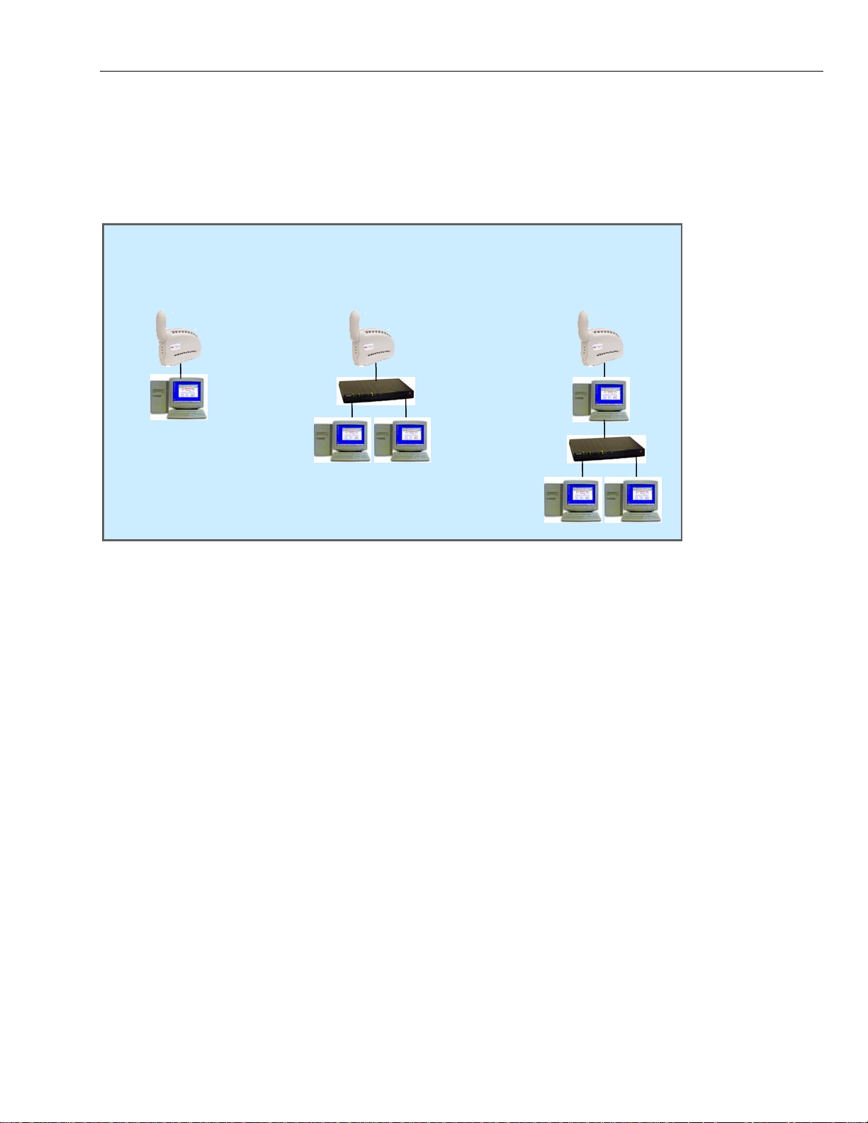
onfiguration Options
C
Host computer used
Host computer used
Modem connected
Modem connected
Modem connected
to a single computer
to a single computer
to a single computer
(Ethernet)
(Ethernet)
(Ethernet)
Modem providing
Modem providing
Modem providing
access to the I
access to the Internet
access to the Internet
via an Etherne
via an Ethernet hub
via an Ethernet hub
nternet
t hub
Host computer used
as a router to network
as a router to network
as a router to network
(USB or Ethernet)
(USB or Ethernet)
(USB or Ethernet)
esults of Correct Navini iagnostics Installation
R D
xperienced PC users can c e f th Dia ins looking at
E heck th
e log file that is created d the ion e is named
th
Navini_Diagnostics_InstallLog.log e iles\Navini
“
iagnostics.
D
uring
results o
installat
.” It is locat
e Navini
process. Th
d under c:\P
gnostics
log file
rogram F
tallation by
-----
--
stall Begin: Tue Jul 20 12:15:22 C 004
In DT 2
stall End: Tue Jul 20 12:15:30 C
reated with Zero G's InstallAnywhere 4.5.3 Enterprise Build 1394
C
ummary
S
-----
--
stallation: Successful with warnin
In gs.
SUCCESSES
2
WARNINGS
1
NONFATAL ERRORS
0
FATAL ERRORS
0
DT 2004 In
34
060210_pv1.6_Ripwave-MX Modem User Guide_40-00382-00b(4.4.2)
3434
Page 35

Navini Networks, Inc. Ripwave MX Modem User Guide
Action Notes:
None.
Install Log Detail:
heck Disk Space: C:\Program
C Files\NavDiag
Status: SUCCESSF
Additional Notes: N
OTE - Required Disk Space: 29,363,315; Free Disk Space: 30,806,179,840
stall Directory: C:\Program F
In
Status: SUCCESSF
et Registry Entry: Key: HKEY_LOCAL_MACHINE\SOFTWARE\Navini Networks\NavDiag, ValueName:
G
stallDirectory
In
Status: WARNING
Additional Notes: WARNING - Win32Exception
ake Registry Entry: Key: HKEY_LOCAL_MACHINE\SOFTWARE\Navini Networks, Value Name: , Value Data:
M
Status: SUCCESSFUL
ake Registry Entry: Key: HKEY_LOCAL_MACHINE\SOFTWARE\Navini Networks\NavDiag, Value Name: , Value
M
ata:
D
Status: SUCCESSFUL
ake Registry Entry: Key: HKEY_LOCAL_MACHINE\SOFTWARE\Navini Networks\NavDiag, Value Name:
M
stallDirectory, Value Data: C:\Program Files\NavDiag
In
Status: SUCCESSFUL
stall Directory: C:\Program Files\NavDiag\Uninstall\
In
Status: SUCCESSF
UL
stall Uninstaller: Navini Diagn nents)
In
Status: SUCCESSF L
U
stall Directory: C:\Program F
In
Status: SUCCESSF
Install File:
Status: SU
stall File: C:\Program File stall\Uninstall NavDiag.lax
In
Status: SUCCESSF L
U
stall Directory: C:\Program Files\
In NavDiag\Uninstall\resource\
Status: SUCCESSF L
U
stall File: C:\Program File
In s\NavDiag\Uninstall\resource\iawin32.dll
Status: SUCCESSFUL
stall File: C:\Program File
In s\NavDiag\Uninstall\resource\remove.exe
Status: SUCCESSF
C:\Program Files\NavDiag\Uninstall\Uninstall NavDiag.exe
CCESSF
UL
iles\NavDiag\
UL
ostics (Install All Uninstaller Compo
iles\NavDiag\jre
UL
UL
s\NavDiag\Unin
UL
35
060210_pv1.6_Ripwave-MX Modem User Guide_40-00382-00b(4.4.2)
3535
Page 36

Navini Networks, Inc. Ripwave MX Modem User Guide
Make Registry Entry: Key:
HKEY_LOCAL_MACHIN
DisplayName, Value Data:
ake Registry Entry: Key:
M
KEY_LOCAL_MACHINE\SOFT e Name:
H WARE\Microsoft\Windows\CurrentVersion\Uninstall\Navini Diagnostics, Valu
ninstallString, Value Data: "C:\Progra
Status: SUCCESSF L
U
stall Uninstaller: Navini Diagn
In ostics (Install All Uninstaller Components)
Status: SUCCESSFUL
reate LaunchAnywhere: Navini Diag
C
Status: SUCCESSFUL
stall File: C:\Program File NavDiag\Navini Diagnostics.exe
In s\
Status: SUCCESSF
UL
stall File: C:\Program Files\Na
In
Status: SUCCESSF L
reate LaunchAnywhere: Navini agnostics.exe (Install All LaunchAnywhere Java Executable Components)
C Di
Status: SUCC
Install Directory
Status: SUCCESSFUL
: C:\Program F
Status: SUCCESSF
E\SOFT lue Name:
Navini Di
WARE\Microsoft\Windows\CurrentVersion\Uninstall\Navini Diagnostics, Va
agnostics
m Files\NavDiag\Uninstall\Uninstall NavDiag.exe" U
nostics.exe (Install All LaunchAnywhere Java Executable Components)
vDiag\Navini Diagnostics.lax
U
ESSF
UL
les\NavDiag\data\ i
U
L
stall Directory: C:\Program Files\
Status: SUCCESSFUL
stall File: C:\Program File
In s\NavDiag\data\images\billboard.gif
Status: SUCCESSF
stall File: C:\Program Files\Na
In
Status: SUCCESSFUL
stall File: C:\Program File
In s\NavDiag\data\images\buttonbar.gif
Status: SUCCESSF
stall File: C:\Program Files\Na
In
Status: SUCCESSFUL
stall File: C:\Program File
In s\NavDiag\data\images\about1.gif
Status: SUCCESSF
stall File: C:\Program File
In
Status: SUCCESSF
NavDiag\data\images\ In
UL
vDiag\data\images\splash.gif
UL
vDiag\data\images\about2.gif
UL
s\NavDiag\data\images\about.gif
UL
stall File: C:\Program Files\NavDiag\data\images\uninstall.gif
In
Status: SUCCESSF
UL
stall Directory: C:\Program F
In
Status: SUCCESSF L
les\NavDiag\data\log\
i
U
36
060210_pv1.6_Ripwave-MX Modem User Guide_40-00382-00b(4.4.2)
3636
Page 37

Navini Networks, Inc. Ripwave MX Modem User Guide
Install Directory: C:\Program F
Status: SUCCESSF
stall File: C:\Program File
In
Status: SUCCESSF
stall File: C:\Program Files\NavDiag\data\lib\navDiag.jar
In
Status: SUCCESSF L
U
stall File: C:\Program Files\NavDiag\data\lib\jfreechart-0.9.13.jar
In
Status: SUCCESSF L
U
stall File: C:\Program Files\NavDiag\data\lib\jcommon-0.8.8.jar
In
Status: SUCCESSF L
U
stall File: C:\Program Files\NavDiag\data\lib\log4j.jar
In
Status: SUCCESSF L
U
stall Directory: C:\Program Files\NavDiag\data\doc\
In
Status: SUCCESSF L
U
iles\NavDiag\data\lib\
UL
s\NavDiag\data\lib\ctl.jar
UL
stall Directory: C:\Program Files\NavDiag\config\
In
Status: SUCCESSFUL
Install File: C:\Program Files\NavDiag\config\NavDiag.lcf
Status: SUCCESSFUL
Install Directory: C:\Documents and Settings\luis\Start Menu\Programs\NavDiag\
Status: SUCCESSFUL
Create Shortcut: C:\Documents and Settings\luis\Start Menu\Programs\NavDiag\Navini Diagnostics.lnk
Status: SUCCESSFUL
Create Shortcut: C:\Documents and Settings\luis\Start Menu\Programs\NavDiag\Uninstall.lnk
Status: SUCCESSFUL
Install Directory: C:\Documents and Settings\luis\Desktop\
Status: SUCCESSFUL
Additional Notes: NOTE - Directory already existed
Create Shortcut: C:\Documents and Settings\luis\Desktop\Navini Diagnostics.lnk
Status: SUCCESSFUL
37
060210_pv1.6_Ripwave-MX Modem User Guide_40-00382-00b(4.4.2)
3737
Page 38

Navini Networks, Inc. Ripwave MX Modem User Guide
ADDENDUM 2: End User Software License Agreement
between
Navini Networks, Inc.
and
Buyer
ARTICLE 1
AGE
ar
unon
-
uyer represents which it is provided to Buyer solely for Buyer’s own computer server location. B
1.1
2
.1
.2 2
2.3
2.4
IMPORTANT MESS
Act of Assent. Inst
License Agreemen
t of License
Gran . The Software and related Documentation, e the intellectual property of Navini
Networks,
exclus
Software based on the term
Agreement to which it is attached. Buye
otherwise transfer the Software to any third parties.
Ownership Rights. Under this Agreement, Buyer does not acquire any rights of ownership in the
Software and
Networks, Inc. to Buyer pursuant to this License Agreement, whether in printed or machine
readable format. Buyer acquires only the right to use the Software and related Documentation
subject to the terms and conditions of this Agreement. Buyer promises to keep the Software in
confidence for the benefit of Navini Networks, Inc. and agrees to destroy or return the Software
and all copies at such time as Buyer chooses to cease using the Software or upon termination or
cancellation of this License Agreement for any reason.
Backup Copies. Buyer may copy the Software for safekeeping (archival) or backup purposes,
provided that all such copies of the Software are subject to the provisions of this License
Agreement, and also provided that each copy shall include in readable format any and all
Assignment. The rights granted in this License Agreement are restricted for use solely by Buyer
and may not be assigned, transferred, or sublicensed, however Buyer may grant access to its
server to End-Users. Each Buyer shall be authorized to make use of the Software in the form in
that it will not use the Software for any purpose that is not expressly delineated in this
Agreement. Further Buyer represents that it will comply with all export, re-export, and other
laws in its use of the Software.
Inc. and are protected b ini Networks, rants to Buyer a personal,
ive, nontransferable wo nse, for revoca se (as permitted herein) of the
alling the S t you have re erstand and accept this
t.
related Documentation and subsequent releases and versions licensed by Navini
oftware indicates tha ad, und
ARTIC
LICEN
y law. Nav Inc. g
rldwide lice ble
s and conditions of this License Agreement and the Master Supply
nction with the server, but only in conju
copyright notices or markings contained in the original. confidential, proprietary, and
Navini Hardware. Buyer is not permitted to rent, sell or
LE 2
SES
r is permitted to install and use the Software on its
38
060210_pv1.6_Ripwave-MX Modem User Guide_40-00382-00b(4.4.2)
3838
Page 39

Navini Networks, Inc. Ripwave MX Modem User Guide
2.5 Suitability.
a. Buyer alone is responsible for determining which software best suits Buyer’s needs, fo
r
installing and operating the Software, and for the results obtained. Accordingly, each
Buyer should determine its needs, and evaluate the Software’s capabilities before making
a final decis
ion about licensing the software.
b. Navini Networks, Inc. makes no representation that the Software conforms to or satisfies
any federal, state, or local laws. Buyer is encouraged to engage professional assistance
from attorneys and engineers to evaluate the suitability of the Software for Buyer’s use.
c. Navini Networks, Inc. makes no claims that the Software is suitable for Buyer’s intended
purposes.
2.6
Remote Digital Access
. Navini Networks, Inc. reserves the right, but is not obligated to digitally
access the Software for the purposes of upgrading and maintaining the Software.
2.7 U.S. GOVERNMENT RESTRICTED RIGHTS. All Software provided to the U.S. Government
pursuant to solicitations issued on or after December 1, 1995 is provided with the commercial
license rights and restrictions described elsewhere herein. All Software provided to the U.S.
Government pursuant to solicitations issued prior to December 1, 1995 is provided with
“Restricted Rights” as provided for in FAR, 48 CFR 52.227-14 (June 1987) or DFAR, 48 CFR
252.227-7013 (Oct 1988), as applicable
ARTICLE 3
TRADE SECRETS
3.1
Trade Secret. Navini Networks, Inc. considers the
Agreement to be a trade secret. Navini Networks, I
licensed Software covered by this License
nc. does not disclose any information to
Navini Networks, Inc. competitors or potential competitors. Buyer shall not disclose any design,
code, or technological know-how gained by access to the Software to Licensor’s
Buyer shall not use design, code, or documentation gained by access to the Software
similar t
echnology or a competing software product. To attempt to or to do so, the Parties
competitors.
to develop a
acknowledge, understand and agree, constitute a material breach of this License Agreement.
3.2
Third Party Intellectual Property
. Buyer acknowledges, understands and agrees that the licensed
Software covered by this License Agreement may contain Intellectual Property owned by Third
Parties and duly licensed to Nav
Party Intellectual Property man
licensed Software. Buyer promises to keep such T
to the benefit of the Third Party, agrees not to reverse engineer or otherwise decom
ini Networks, Inc. Copyright, Patent and other laws protect Third
ufactured with, marketed with, or otherwise bundled with the
hird Party Intellectual Property in confidence
pile Third
Party Intellectual Property, and agrees to stop using, destroy and/or return such Third Party
ned Intellectual Property under the same terms and conditions as the licensed Software as set
ow
forth in this License Agreement.
39
060210_pv1.6_Ripwave-MX Modem User Guide_40-00382-00b(4.4.2)
3939
Page 40

Navini Networks, Inc. Ripwave MX Modem User Guide
ARTICLE 4
INDEMNIFICATIONS AND WARRANTY
.1
Intellectual Property Indemnification; Entire Liability4. ARTICLE 15 OF THE SUPPLY
AGREEMENT TO WHICH THIS A
GREEMENT IS ATTACHED STATES THE ENTIRE
LIABILITY OF NAVINI NETWORKS, INC. WITH RESPECT TO INFRINGEMENT OF
COPYRIGHTS, TRADE SECRETS, TRADEMARKS, PATENTS, AND OTHER
INTELLECTUAL PROPERTY RI
DOCUMENTATION, OR
ANY PARTS THEREOF, AND NAVINI NETWORKS, INC.
GHTS BY THE LICENSED SOFTWARE,
SHALL HAVE NO ADDITIONAL LIABILITY WITH RESPECT TO ANY ALLEGED OR
PROVEN INFRINGEMENT.
4.2
Warranty. EXCEPT AS GRANTED IN THE BODY OF THE SUPPLY AGREEMENT TO
WHICH THIS LICENSE AGREEMENT IS ATT
ACHED, THE LICENSED SOFTWARE IS
PROVIDED BY NAVINI NETWORKS, INC. “AS IS” AND WITHOUT WARRANTY OF
ANY KIND OR NATURE, WRITTEN OR ORAL, EXPRESS OR IMPLIED, INCLUDING
(WITHOUT LIMITATION
) THE IMPLIED WARRANTIES OF MERCHANTABILITY AND
FITNESS FOR A PARTICULAR PURPOSE. THIS LIMITATION OF WARRANTIES WAS A
MATERIAL FACTOR IN THE ESTABLISHMENT OF THE LICENSE FEE CHARGED FOR
EACH SPECIFIC ITEM O
F SOFTWARE LICENSED.
TICLE 5
AR
LIMITATION OF LIABILITY
5.1
Consequential Damages. TO THE MAXIMUM EXTENT PERMITTED BY THE APPLICABLE
LAW, IN NO EVENT SHALL NAVINI NETWORKS, INC. OR ANY THIRD PARTY
ATION, PRODUCTION, DELIVINVOLVED IN THE CRE
ERY, OR LICENSING OF THE
SOFTWARE BE LIABLE FOR ANY LOST REVENUES, PROFITS OR DATA OR OTHER
L, CONSEQUENTIAL, OR PUNITIVE DAMAGES,
LEDGE, ACTUAL OR
AGES.
.2
SPECIAL, INDIRECT, INCIDENTA
HOWEVER CAUSED AN
D REGARDLESS OF THEORY OF LIABILITY, EVEN IF NAVINI
NETWORKS, INC. HAS, OR SHOULD HAVE HAD ANY KNOW
E POSSIBILITY OF SUCH DAMCONSTRUCTIVE, OF TH
License-Fee Limitation5. Except for the indemnification provisions of Article 15, Navini
Networks, Inc.’s maximum liability for damages is limited to the license fees paid by Buyer under
ed the damages. this Agreement for the particular licensed Software that caus
5.3
Loss of Data. Software error can cause a significant loss of data. Navini Networks, Inc. shall not
be responsible for any loss of data. Navini Network
in this License AgreemSoftware error as provided
s, Inc.’s responsibility is to correct the
ent or the Supply Agreement to which it is
attached. It is Licensee’s responsibility to have adequate backup procedures to protect Buyer
from significant loss of valid data.
40
060210_pv1.6_Ripwave-MX Modem User Guide_40-00382-00b(4.4.2)
4040
Page 41

Navini Networks, Inc. Ripwave MX Modem User Guide
ARTICLE 6
CT CODE ONLY-NO MODIFICATIONS
OBJE
6.1
Modifications. In o
rder to maintain the “trade secret” status of the information contained in the
Licensed Software, Navini Networks, Inc. provides the Software in object-code form only. Buyer
shall not modify, enhance, adapt, disassemble, translate, decompile or
portion of the object code
license to the Software object code. The object code contain
and other license informati
of the Software module. Buyer shall not use the Software without a
s the license number, date of license,
on. This information is placed in the object-code portions to prevent
otherwise decode any
unauthorized and unlicensed distributions of the Software. Buyer shall not subvert or change any
ntation
6.2
of this information. Further Buyer shall not make, full or partial, copies of any docume
whether printed or machin
expressly granted prior written permission by Navini
Responsibility for Damage . Buyer is subject to the provisions of the Supply Agreement with
e- readable media supplied with the Licensed Software unless
Networks, Inc.
s
respect to the Software (including Section 16). Buyer is fully liable and responsible for any
damages, indirect or direct, and costs that Navini Networks, Inc. m
s the Software without Nasubcontractor who accesse
defend, indemnify, and hold Navini Networks, In
vini’s prior written consent. Buyer shall
c., its directors, officers, employees, agents,
Authorized Partners, and other representatives harmless accordingly for all costs and dir
indirect damages sustained
by Navini Networks, Inc. However, if the subcontractor is pre-
ay incur if Buyer appoints a
ect and
approved by Navini in writing for access to the Software, then this Section shall not apply.
6.3
Copyright Notices. Buyer
shall not remove any copyright or proprietary rights notice or
identification that indicates Navini Networks,
Software, it being expressly understood and a
should not be construed as
an admission or presumption that publication of the licensed Software
Inc. ownership from any part of the licensed
greed that the existence of such copyright notice
has occurred.
ND OF AGREEMENT
E
Copyright © 2001-2006 Navini N
etworks, Inc.
All rights reserved. Printed in the
USA.
Navini Networks is a registered trademark. Zero-Install, Rip
trademarks of Navini Networks, In
c. Other product and company names mentioned herein may be
trademarks and/or service marks of their respective owner
wave, and Unwired by Navini are
s. Rev. 052302
41
060210_pv1.6_Ripwave-MX Modem User Guide_40-00382-00b(4.4.2)
4141
 Loading...