


Industrial Cellular VPN Router
NR500 Standard User Manual
Guangzhou Navigateworx Technologies Co, Ltd
www.navigateworx.com

Industrial Cellular VPN Router NR500 Series User Manual
Page 1 / 78
REVISION HISTORY
Revision
Date
Revision Details
0
May 2018
Initial release.
1
Aug 2018
Add Schedule Reboot, OpenVPN, IPSec
2
Oct 2018
Add SSH, GRE, VRRP, Wi-Fi Client
Trademarks and copyright
Guangzhou Navigateworx Technologies Co, Ltd and & logo are the
trademarks or registered trademarks in China mainland, HongKong and other countries
worldwide. All other trademarks mentioned in this document are the property of their respective
owners.
@2018 Navigateworx Technologies. All Rights Reserved.
Disclaimers
Information in this document is subject to change without notice and does not represent a
commitment on the part of Navigateworx Technologies.
Navigateworx Technologies provides this document as is, without warranty of any kind, either
expressed or implied, including, but not limited to, its particular purpose. Navigateworx
Technologies may make improvements and/or changes in this manual, or in the product(s) and/or
the program(s) described in this manual at any time.
Information provided in this manual is intended to be accurate and reliable. However,
Navigateworx Technologies assumes no responsibility for its use, or for any infringements on the
rights of third parties that may result from its use.
Technical Support
E-mail: support@navigateworx.com
info@navigateworx.com
Web: www.navigateworx.com

Industrial Cellular VPN Router NR500 Series User Manual
Page 2 / 78
Interference Issues
Avoid possible radio frequency (RF) interference by following these guidelines:
• The use of cellular telephones or devices in aircraft is illegal. Use in aircraft may endanger operation and
disrupt the cellular network. Failure to observe this restriction may result in suspension or denial of cellular
services to the offender, legal action, or both.
• Do not operate in the vicinity of gasoline or diesel fuel pumps unless use has been approved or
authorized.
• Do not operate in locations where medical equipment that the device could interfere with may be in
use.
• Do not operate in fuel depots, chemical plants, or blasting areas unless use has been approved and
authorized.
• Use care if operating in the vicinity of protected personal medical devices, i.e., hearing aids and
pacemakers.
• Operation in the presence of other electronic equipment may cause interference if equipment is
incorrectly protected. Follow recommendations for installation from equipment manufacturers.
Declaration of Conformity
NR500 Series products are in conformity with the essential requirements and other relevant provisions of the
CE and RoHS.

Industrial Cellular VPN Router NR500 Series User Manual
Page 3 / 78
Table of Contents
Chapter 1. Product Overview ................................................................................................................................. 5
1.1 Overview ................................................................................................................................................. 5
1.2 Features and Benefits .......................................................................................................................... 5
1.3 General Specifications ........................................................................................................................ 6
1.4 Mechanical Specifications ................................................................................................................ 8
1.5 Package Checklist ................................................................................................................................ 9
1.6 Order Information ............................................................................................................................... 11
Chapter 2. Installation ............................................................................................................................................. 12
2.1 Product Overview ............................................................................................................................... 12
2.2 LED Indicators ....................................................................................................................................... 14
2.3 Ethernet Port Indicator....................................................................................................................... 15
2.4 PIN Definition of Terminal block ...................................................................................................... 15
2.5 Reset Button .......................................................................................................................................... 16
2.6 Insert SIM card ...................................................................................................................................... 16
2.7 Install Antenna ..................................................................................................................................... 17
2.8 DIN-rail Mounting................................................................................................................................. 18
2.9 Protective Grounding Installation ................................................................................................... 18
2.10 Power Supply Installation .................................................................................................................. 19
2.11 Power On The Router ......................................................................................................................... 19
Chapter 3. Access to Web page ......................................................................................................................... 20
3.1 PC Configuration ................................................................................................................................ 20
3.2 Factory Default Settings .................................................................................................................... 21
3.3 Login to Web Page............................................................................................................................. 22
Chapter 4. Web Configuration ............................................................................................................................. 23
4.1 Web Interface ...................................................................................................................................... 23
4.2 Overview ............................................................................................................................................... 25
4.2.1 Status ...................................................................................................................................................... 25
4.2.2 Syslog ...................................................................................................................................................... 27
4.3 Link Management ............................................................................................................................... 28
4.3.1 Connection Manager ....................................................................................................................... 28
4.3.2 Cellular ................................................................................................................................................... 31
4.3.3 Ethernet .................................................................................................................................................. 34
4.3.4 Wi-Fi ......................................................................................................................................................... 39
4.4 Industrial Interface .............................................................................................................................. 44
4.4.1 Serial ........................................................................................................................................................ 44
4.4.2 Digital IO ................................................................................................................................................ 48
4.5 Network .................................................................................................................................................. 50
4.5.1 Firewall.................................................................................................................................................... 50
4.5.2 Route ...................................................................................................................................................... 52
4.5.3 VRRP ........................................................................................................................................................ 53
4.6 Applications .......................................................................................................................................... 55
4.6.1 DDNS ....................................................................................................................................................... 55
4.6.2 Schedule Reboot ................................................................................................................................ 56

Industrial Cellular VPN Router NR500 Series User Manual
Page 4 / 78
4.7 VPN .......................................................................................................................................................... 57
4.7.1 OpenVPN .............................................................................................................................................. 57
4.7.2 IPSec ....................................................................................................................................................... 62
4.7.3 GRE .......................................................................................................................................................... 65
4.8 Maintenance ....................................................................................................................................... 66
4.8.1 Upgrade ................................................................................................................................................ 66
4.8.2 System .................................................................................................................................................... 67
4.8.3 Configuration ....................................................................................................................................... 71
4.8.4 Debug Tools .......................................................................................................................................... 71
Appendix A -Glossary ............................................................................................................................................... 73
Appendix B -Q&A ...................................................................................................................................................... 74
No Signal ...................................................................................................................................................... 74
Cannot detect SIM card ......................................................................................................................... 74
Poor Signal ................................................................................................................................................... 74
IPSec VPN established, but LAN to LAN cannot communicate ................................................... 75
Forget Router Password ........................................................................................................................... 75
Appendix C -Digital IO Scenario ........................................................................................................................... 76
Appendix D - CLI ........................................................................................................................................................ 77

Industrial Cellular VPN Router NR500 Series User Manual
Page 5 / 78
Chapter 1. Product Overview
1.1 Overview
Navigateworx NR500 series industrial cellular VPN router offers a single, flexible platform to address
a variety of wireless communications needs with over-the-air configuration and system monitoring
for optimal connectivity. This router enables wireless data connectivity over public and private LTE
cellular networks at 4G speeds.
NR500 series router has dual SIM backup, 2 or 4 LAN ports, 1 port could be changed to Ethernet
WAN connection (for fixed internet fail over to cellular). An optional 802.11 b/g/n Wi-Fi interface
access point and client operations supports connectivity to IP applications in a variety of different
connection scenarios. RS232 and RS485 interfaces are provided to support Serial to IP
communication. NR500 series router also support 2 x digital input and 2 x Digital output for alarm
applications.
NR500 series router supports 9 to 48 VDC wide range power inputs, designed with reverse-voltage
protection mechanism for greater reliability. It is an advanced choice for universal wireless M2M
applications with reliable features for data transmission.
1.2 Features and Benefits
Industrial internet access
• Wireless Mobile Broadband 2G / 3G / 4G Connection
• Remote access to SCADA System for Industrial Automation
• Reduce high costs for on-site maintenance
Designed for industrial usage
• Power Input Range 9 to 48 VDC
• Industrial designed for harsh environment
• Compact metal casing for easy mounting
Secure and reliable remote connection
• Connection manager ensure seamless communication
• Support Multiple VPN tunnels for data encryption
• Firewall prevents unsafe and unauthorized access

Industrial Cellular VPN Router NR500 Series User Manual
Page 6 / 78
Easy to use and easy maintenance
• User-friendly web interface for human interaction
• Easy configuration for deployment
• Support 3rd Party remote management cloud
1.3 General Specifications
Cellular Interface
• Standards: FDD-LTE/TDD-LTE, WCDMA/UMTS/HSPA/HSPA+/EDGE/GPRS,
• 2× SMA female antenna connector
• 2 x SIM (3.0V & 1.8V)
Wi-Fi Interface (Optional)
• Standards: 802.11b/g/n, 300Mbps
• 2 x RP-SMA male antenna connector
• Support Wi-Fi AP and Client modes
• Security: WEP, WPA and WPA2 encryption
• Encryption: AES, TKIP, WEP64
Ethernet Interface
• Standard: IEEE 802.3, IEEE 802.3u
• Number of Ports:
NR500-Standard: 2 x 10/100 Mbps, RJ45 connector
NR500-Pro: 4 x 10/100 Mbps, RJ45 connector
• 1 x WAN interface (configurable on Web GUI)
• 1.5KV magnetic isolation protection
Serial Interface
• 1×RS232 (3 PIN): TX, RX, GND
• 1 x RS485 (2 PIN): Data+(A), Data-(B)
• Baud rate: 300 bps to 115200 bps
• Connector: terminal block
• 15KV ESD protection

Industrial Cellular VPN Router NR500 Series User Manual
Page 7 / 78
DI/DO Interface
• Type: 2 x DI + 2 x DO
• Connector: terminal block
• Isolation: 3KVDC or 2KVrms
• Absolute maximum VDC: 36VDC
• Absolute maximum ADC: 100mA
Other Interfaces
• 1× RST button
• LED instruction: 1 x SYS, 1 x NET, 1 x USR, 3 x RSSI
Software
• Network protocols: DHCP, ICMP, PPPoE, HTTP, HTTPS, DNS, VRRP, NTP…
• VPN: IPSec, PPTP/L2TP client, GRE, OpenVPN, DMVPN
• Policy: RIPv2/OSPF/BGP dynamic route (optional)
• Firewall & Filter: Port forwarding, DMZ, anti-DoS, ACL
• Serial port: TCP server and client, UDP
• Management: Web, SNMP, 3
rd
party platform
Power Supply and Consumption
• Connector: 3-pin 3.5 mm female socket with lock
• Input voltage range: 9~48VDC
• Power consumption:
Idle: 100 mA@12V
Data link: 400 mA (peak) @12V
Physical Specification
• Ingress Protection: IP30
• Housing & Weight: Metal, 300g
• Dimension: 104mm x 104mm x 38mm (excluding antenna)
• Installations: Din-rail mounting
Environmental
• Operation temperature: -40~+75℃
• Store temperature: -40~+85℃
• Operation humidity: 5% to 95% non-condensing

Industrial Cellular VPN Router NR500 Series User Manual
Page 8 / 78
1.4 Mechanical Specifications
Dimension: 104mm x 104mm x 38mm (excluding antenna)

Industrial Cellular VPN Router NR500 Series User Manual
Page 9 / 78
1.5 Package Checklist
NR500 series Router includes the parts shown in below, please verify your components.
NOTE: if any of the below items is missing or damaged, please contact your sales representative.
Included equipment
• 1 x Naviageteworx NR500 series Industrial Cellular VPN router (Wi-Fi optional)
NR500 Standard NR500 Pro
or
• 1 x 3-pin 3.5 mm male terminal block with lock for power supply
• 1 x 10-pin 3.5 mm male terminal block for RS232/RS485/DI/DO
• 1 x Ethernet cable

Industrial Cellular VPN Router NR500 Series User Manual
Page 10 / 78
• 1 x Quick Start Guide
Optional Accessories (sold separately)
• 3G/4G cellular antenna
Stubby antenna Magnet antenna
• RP-SMA Wi-Fi antenna
Stubby antenna Magnet antenna
• 35mm Din-rail mounting kit

Industrial Cellular VPN Router NR500 Series User Manual
Page 11 / 78
• AC/DC power adapter (12VDC, 1.5A; EU/US/UK/AU plug optional)
1.6 Order Information
Model
Part Number
Description
NR500-S4G
A502433
4G LTE, Dual SIMs, 2 x Eth, 1 x RS232 (3 PIN), 1 x RS485,
2 x DI, 2 x DO, 9 - 48VDC
A512433
4G LTE, Dual SIMs, 2 x Eth, 1 x RS232 (3 PIN), 1 x
RS485, 2 x DI, 2 x DO, 9 - 48VDC,
2.4GHz Wi-Fi
NR500-S3G
A502333
3G, Dual SIMs, 2 x Eth, 1 x RS232 (3 PIN), 1 x RS485, 2
x DI, 2 x DO, 9 - 48VDC
A512333
3G, Dual SIMs, 2 x Eth, 1 x RS232 (3 PIN), 1 x RS485, 2
x DI, 2 x DO, 9 - 48VDC, 2.4GHz Wi-Fi
NR500-P4G
A504433
4G LTE, Dual SIMs, 4 x Eth, 1 x RS232 (3 PIN), 1 x RS485,
2 x DI, 2 x DO, 9 - 48VDC
A514433
4G LTE, Dual SIMs, 4 x Eth, 1 x RS232 (3 PIN), 1 x
RS485, 2 x DI, 2 x DO, 9 - 48VDC,
2.4GHz Wi-Fi
NR500-P3G
A504333
3G, Dual SIMs, 4 x Eth, 1 x RS232 (3 PIN), 1 x RS485, 2
x DI, 2 x DO, 9 - 48VDC
A514333
3G, Dual SIMs, 4 x Eth, 1 x RS232 (3 PIN), 1 x RS485, 2
x DI, 2 x DO, 9 - 48VDC, 2.4GHz Wi-Fi

Industrial Cellular VPN Router NR500 Series User Manual
Page 12 / 78
Chapter 2. Installation
2.1 Product Overview
• Front Panel
① Wi-Fi Antenna
② MAIN Cellular Antenna
③ LED Indicator
④ Serial port & DIDO
⑤ Ethernet port
⑥ Wi-Fi Antenna
⑦ AUX Cellular Antenna
• Left Side Panel
① SIM Card Slot
② Reset Button
③ Power Connector
④ Grounding Stud

Industrial Cellular VPN Router NR500 Series User Manual
Page 13 / 78

Industrial Cellular VPN Router NR500 Series User Manual
Page 14 / 78
2.2 LED Indicators
Name
Color
Status
Description
SYS
Green
Slow Blinking (500ms duration)
Operating normally
Fast Blinking
System initialing
Off
Power is off
NET
Green
On
Register to Highest priority network
service (depend on Radio, e.g.
Radio support LTE as Highest priority
network).
Fast Blinking (250ms duration)
Register to Non-Highest priority
network service (depend on Radio,
e.g. Radio support LTE as Highest
priority network, then WCDMA and
GPRS is non-highest priority network).
Off
Register failed
USR: SIM
Green
On
Router is trying cellular connection
with SIM1
Fast Blinking (250ms duration)
Router is trying cellular connection
with SIM2
Off
No SIM detected
USR: Wi-Fi
Green
On
Wi-Fi is enabled and data
transmission
Off
Wi-Fi is disable or initialize failed
Signal Strength
Indicator
Green
On, 3 LED light up
Signal strength (21-31) is high
On, 2 LED light up
Signal strength (11-20) is medium
On, 1 LED light up
Signal strength (1-10) is low
Off
No signal

Industrial Cellular VPN Router NR500 Series User Manual
Page 15 / 78
2.3 Ethernet Port Indicator
Name
Status
Description
Link indicator
On
Connection is established
Blinking
Data is being transmitted
Off
Connection is not established
NOTE:There are two LED indicators for each Ethernet port. Due to the chipset design NR500 router
would only light up the green one(Link indicator) on left side, the right LED is Off without meaning.
2.4 PIN Definition of Terminal block
• Serial Port & DIDO
PIN
RS232
RS485
DI
DO
Direction
1
--
--
--
DO1
Router-->Device
2
--
--
--
DO2
Router-->Device
3
--
--
--
COM
--
4
-- A --
--
Router<-->Device
5
-- B --
--
Router<-->Device
6
--
--
DI1
--
Router<--Device
7
--
--
DI2
--
Router<--Device
8
GND
--
--
--
--
9
TX
--
--
--
Router-->Device
10
RX
--
--
--
Router<--Device

Industrial Cellular VPN Router NR500 Series User Manual
Page 16 / 78
• Power Input
PIN
Description
V+ (Red line)
Positive
V- (Yellow line)
Negative
PGND
GND
2.5 Reset Button
Function
Action
Reboot
Press the RST button within 3s under operation status
Factory Reset
Press the RST button between 3s to 10s, all LED blink few times then
reboot automatically.
2.6 Insert SIM card
• Insert / Remove SIM card
1. Make sure the power is disconnected.
2. Use a Philips-head screwdriver to remove SIM slot cover.
3. Insert the SIM card(s) in to the SIM sockets.
4. Replace the SIM slot cover.

Industrial Cellular VPN Router NR500 Series User Manual
Page 17 / 78
2.7 Install Antenna
• Connect the cellular antenna to the MAIN and AUX connector on the unit.
NOTE: NR500 router supports dual antennas with MAIN and AUX connectors. MAIN connector is for
data receiving and transmission. AUX connector is for enhancing signal strength, which cannot be
used separately.
• Connect the Wi-Fi antenna to the Wi-Fi connector on the unit.

Industrial Cellular VPN Router NR500 Series User Manual
Page 18 / 78
2.8 DIN-rail Mounting
1. Use 4 pcs of M3x6 flat head phillips screws to fix the DIN-rail to the router.
2. Insert the upper lip of the DIN-rail into the DIN-rail mounting kit.
3. Press the router towards the DIN-rail until it snaps into place.
2.9 Protective Grounding Installation
1. Remove the grounding nut.
2. Connect the grounding ring of the cabinet’s grounding wire onto the grounding stud and screw
up the grounding nut.
NOTE: Strongly recommended the router to be grounded when deployed.

Industrial Cellular VPN Router NR500 Series User Manual
Page 19 / 78
2.10 Power Supply Installation
1. Remove the pluggable connector from the unit, then loosen the screws for the locking flanges
as needed.
2. Connect the wires of the power supply to the terminals.
2.11 Power On The Router
1. Connect one end of the Ethernet cable to the LAN port on the unit and the other end to a LAN
port on a PC.
2. Connect the AC power to a power source.
3. Router is ready when SYS LED is blinking.

Industrial Cellular VPN Router NR500 Series User Manual
Page 20 / 78
Chapter 3. Access to Web page
3.1 PC Configuration
NR500 router contains a DHCP server which will automatically assign an IP address to your PC,
however in some cases the user may need to change the network settings on their PC to accept
the IP address from the NR500. or you can configure a static IP address manually.
• Obtain an IP address automatically
The process required to do this differs depending on the version of Windows you are using.
NOTE: The following steps are based on Windows 7.
select Start » Control Panel » Network Connections. Right click Local Area Connection and select
Properties to open the configuration dialog box for Local Area Connection. Select Internet
Protocol (TCP/IP) and click Properties to open the TCP/IP configuration window. On the General
tab, select Obtain an IP address automatically and Obtain DNS server address automatically.
Click OK to complete TCP/IP configuration.

Industrial Cellular VPN Router NR500 Series User Manual
Page 21 / 78
• Set to a static IP address
click "Use the following IP address" to assign a static IP manually within the same subnet of the
router.
NOTE:Default gateway and DNS server is not necessary if PC not routing all traffic go through
NR500 router.
3.2 Factory Default Settings
NR500 router supports Web-based configuration interface for management. If this is the first time
for you to configure the router, please refer to below default settings.
Username: admin
Password: admin
LAN IP Address: 192.168.5.1 (Eth0~Eth1/Eth3 bridge as LAN mode)
DHCP Server: Enabled

Industrial Cellular VPN Router NR500 Series User Manual
Page 22 / 78
3.3 Login to Web Page
1. Start a Web browser on your PC (Chrome and IE are recommended), enter 192.168.5.1 into the
address bar of the web browser.
2. Then use the default username and password(admin/admin), to log in to the router.
.

Industrial Cellular VPN Router NR500 Series User Manual
Page 23 / 78
Chapter 4. Web Configuration
4.1 Web Interface
The NR500 router Web interface is divided into two sections. In the left pane is the main navigation
menu. On the right is the content area for each page.
NOTE: The navigation menu may contain fewer sections than shown here depending on which
options are installed in your unit.
Industrial Cellular VPN Router NR500 Series User Manual
Page 24 / 78
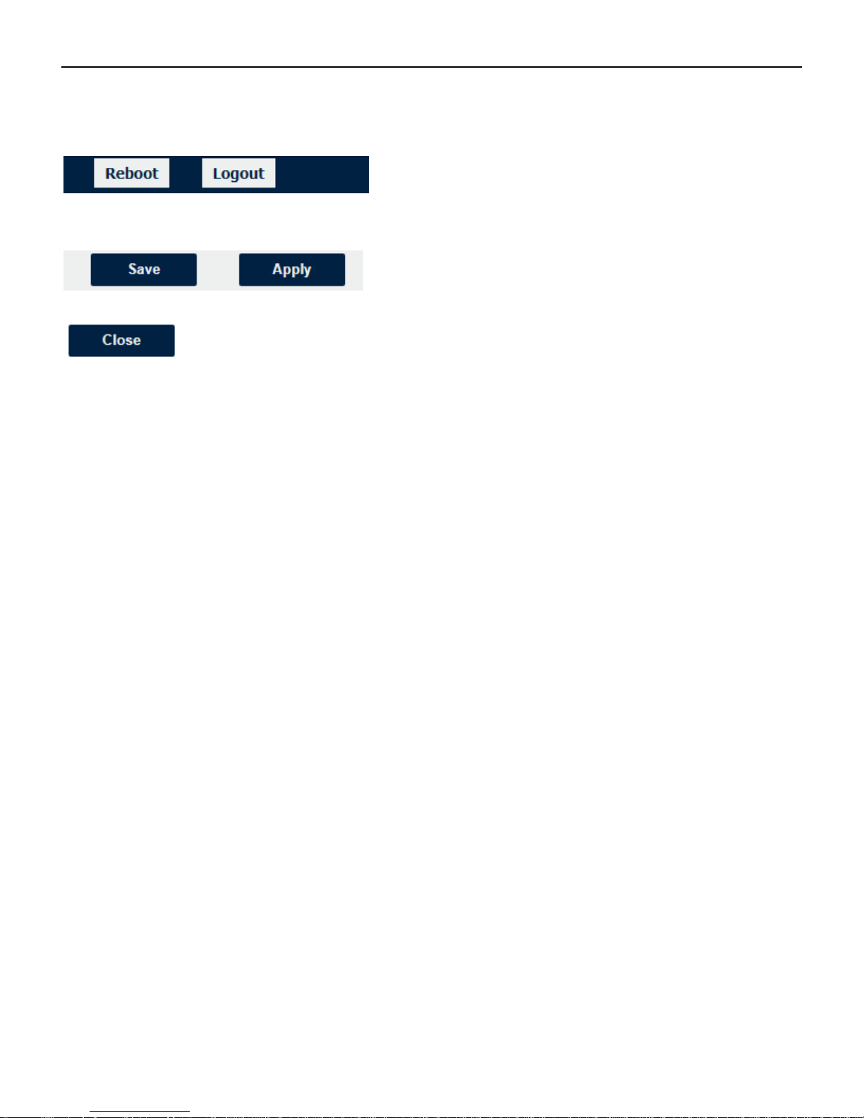
• Reboot: reset the router within power disconnect.
• Logout: logout to web authorization page.
• Save: save the configuration on current page.
• Apply: apply the changes on current page immediately.
• Close: exit without changing the configuration on current page.

Industrial Cellular VPN Router NR500 Series User Manual
Page 25 / 78
4.2 Overview
4.2.1 Status
You can view the system information of the router on this page.
System Information
• Device Module
Displays the model name of router
• System Uptime
Displays the duration the system has been up in hours, minutes and seconds.
• System Time
Displays the current date and time.
• RAM Usage
Displays the RAM capacity and the available RAM memory.
• Firmware Version
Displays the current firmware version of router.
• Kernel Version
Displays the current kernel version of router.
• Serial Number
Display the serial number of router.

Industrial Cellular VPN Router NR500 Series User Manual
Page 26 / 78
Active Link Information
• Link Type
Current interface for internet access.
• IP Address
Displays the IP address assigned to this interface.
• Netmask
Displays the subnet mask of this interface.
• Gateway
Displays the gateway of this interface. This is used for routing packets to remote networks.
• Primary DNS Server
Displays the primary DNS server of this interface.
• Secondary DNS Server
Displays the secondary DNS server of this interface.

Industrial Cellular VPN Router NR500 Series User Manual
Page 27 / 78
4.2.2 Syslog
Syslog Information
• Download Diagnosis
Download the Diagnosis file for analysis.
• Download Syslog
Download the complete syslog since last reboot.
• Clear
Clear the current page syslog printing.
• Refresh
Reload the current page with latest syslog printing.
Industrial Cellular VPN Router NR500 Series User Manual
Page 28 / 78
4.3 Link Management
This section shows you the setup of link management.
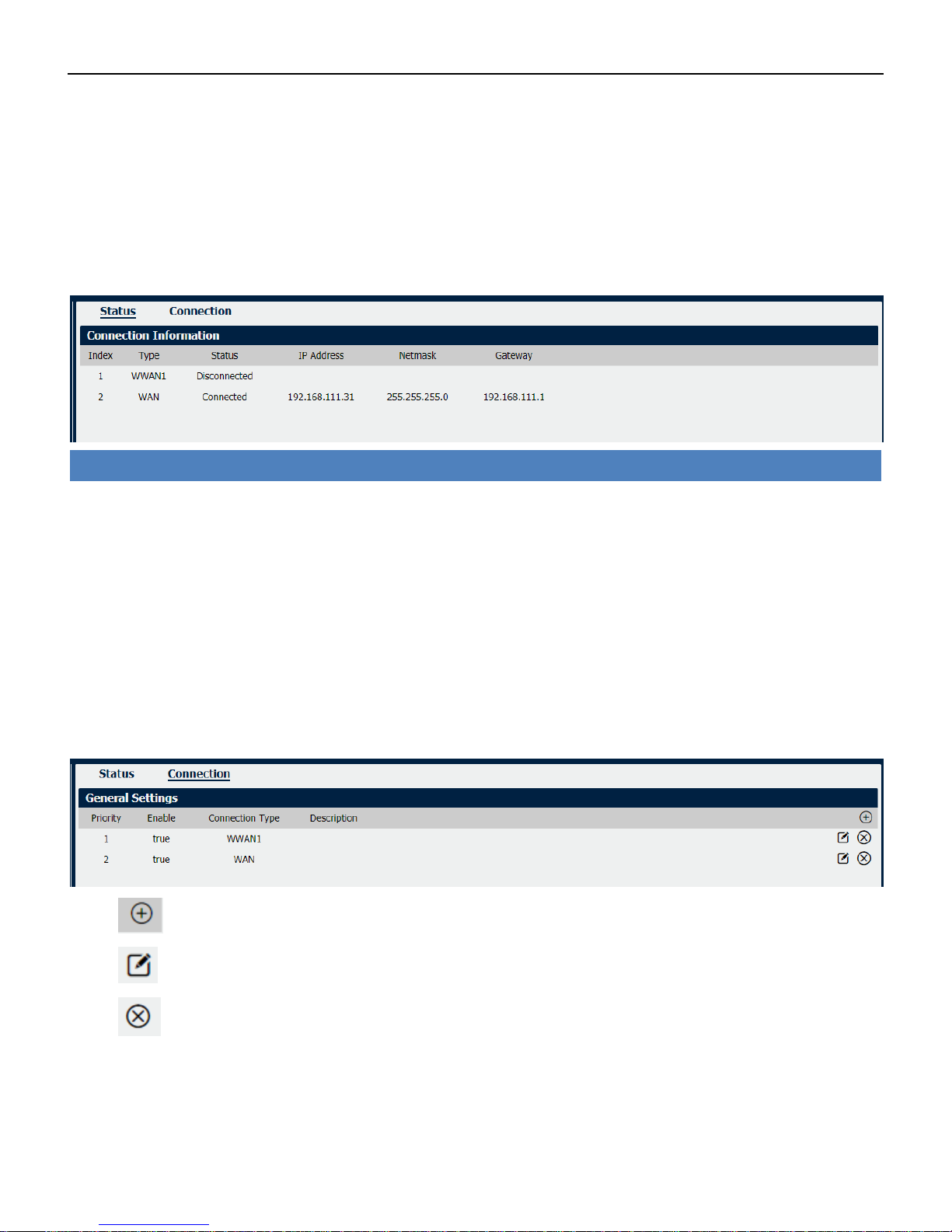
4.3.1 Connection Manager
Click to add a new priority interface.
Click to edit current interface settings.
Click to delete current interface.
Connection Manager->Status
• Type
Displays the connection interface
• Status
Displays the connection status of this interface.
• IP Address
Displays the IP Address of this interface.
• Netmask
Displays the subnet mask of this interface.
• Gateway
Displays the gateway of this interface. This is used for routing packets to remote networks.

Industrial Cellular VPN Router NR500 Series User Manual
Page 29 / 78
Connection Settings
• Priority
Displays current index on priority list.
• Connection Type
Select the available interface as outbound link.
NOTE: specify SIM1 carrier link as WWAN1, SIM2 carrier link as WWAN2.
• ICMP Detection Settings->Enable
Check this box to detect link connection status based on pings to a specified IP address.
• Primary Server
Enter the primary IP address that pings will be sent to, to detect the link state. Recommend entering
the IP address of known external reachable server or network (e.g. 8.8.8.8).
• Secondary Server
Enter the secondary IP address that pings will be sent to, when the primary server is ping failed, router
would try to ping the secondary server.
Connection Manager->Connection
• Priority
Displays the priority list of default routing selection.
• Enable
Displays the connection enable status.
• Connection Type
Displays the name of this interface.
• Description
Displays the description of this connection.

Industrial Cellular VPN Router NR500 Series User Manual
Page 30 / 78
• Interval
The duration of each ICMP detection in seconds.
• Retry Interval
The interval in seconds between each ping if no packets have been received.
• Timeout
Enter timeout for received ping reply to determine the ICMP detection failure.
• Retry Times
Displays the outbound interface of this route.
Industrial Cellular VPN Router NR500 Series User Manual
Page 31 / 78
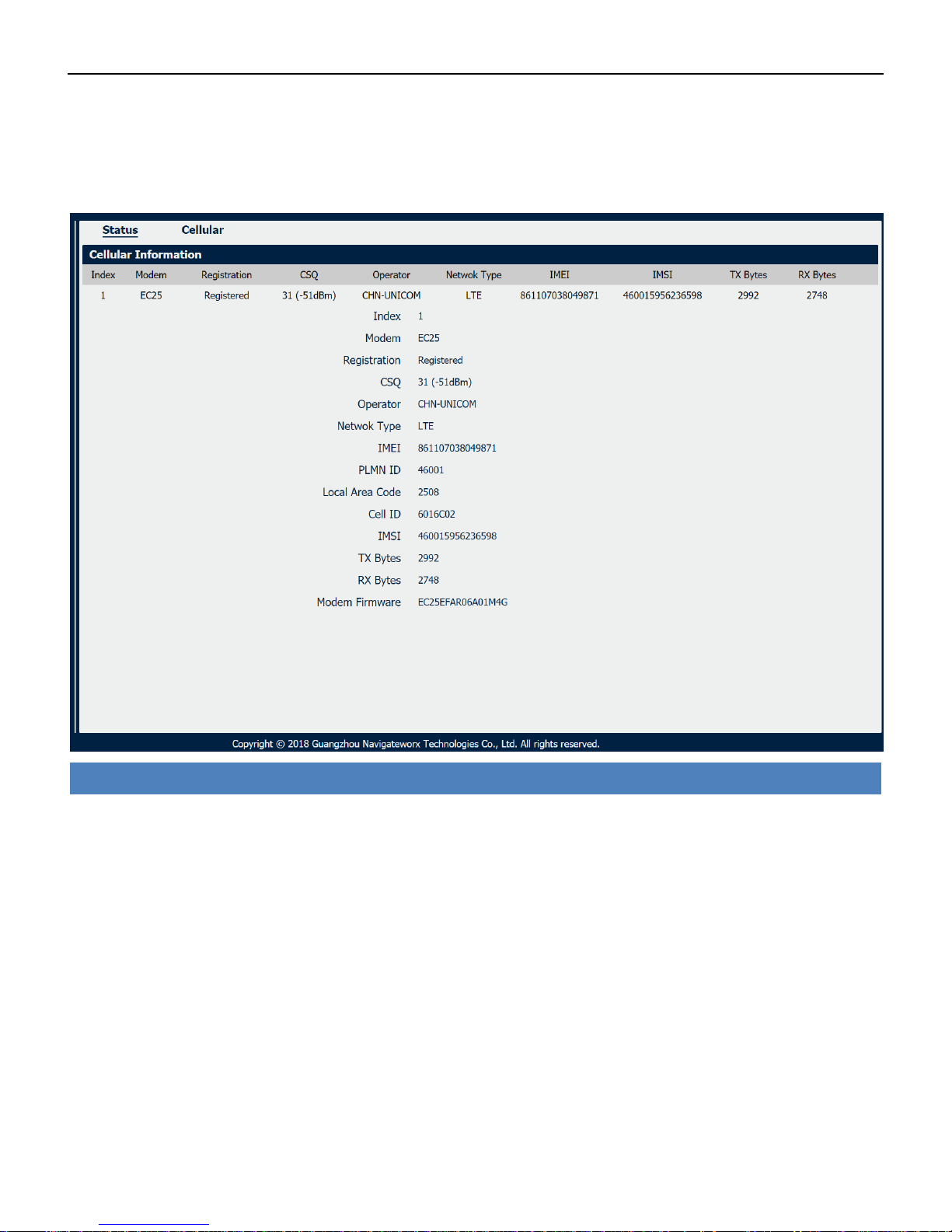
4.3.2 Cellular
NR500 Router main function is connecting to Internet by cellular modem.
Cellular->Status
• Modem
Displays the model of the modem used by this WWAN interface.
• Registration
Displays the registration status of SIM card.
• CSQ
Displays the signal strength of the carrier network.
• Operator
Displays the wireless network provider.
• Network Type
Displays the RF technology currently active. Example: LTE, UMTS, or CDMA.
• IMEI
International Mobile Electronic Identifier. Depending on the carrier and technology used, this may be
required for the carrier when activating the data contract. In some cases this will be blank.
• PLMN ID
Industrial Cellular VPN Router NR500 Series User Manual
Page 32 / 78
Displays the current PLMN ID, including MCC, MNC, LAC and Cell ID.
• Local Area Code
Displays the location area code of the SIM card.
• Cell ID
Displays the Cell ID of the SIM card location.
• IMSI
International Mobile Subscriber Identity, as read from the SIM. This is the user’s network subscription.
• TX Bytes
Displays the total bytes transmitted since the time the unit was connected. NR500 router would
record this data with same SIM card, reboot would not erase this data.
• RX Bytes
Displays the total bytes received since the time the unit was connected. NR500 router would record
this data with same SIM card, reboot would not erase this data.
• Modem Firmware
Displays firmware version of the modem used by the WWAN interface.
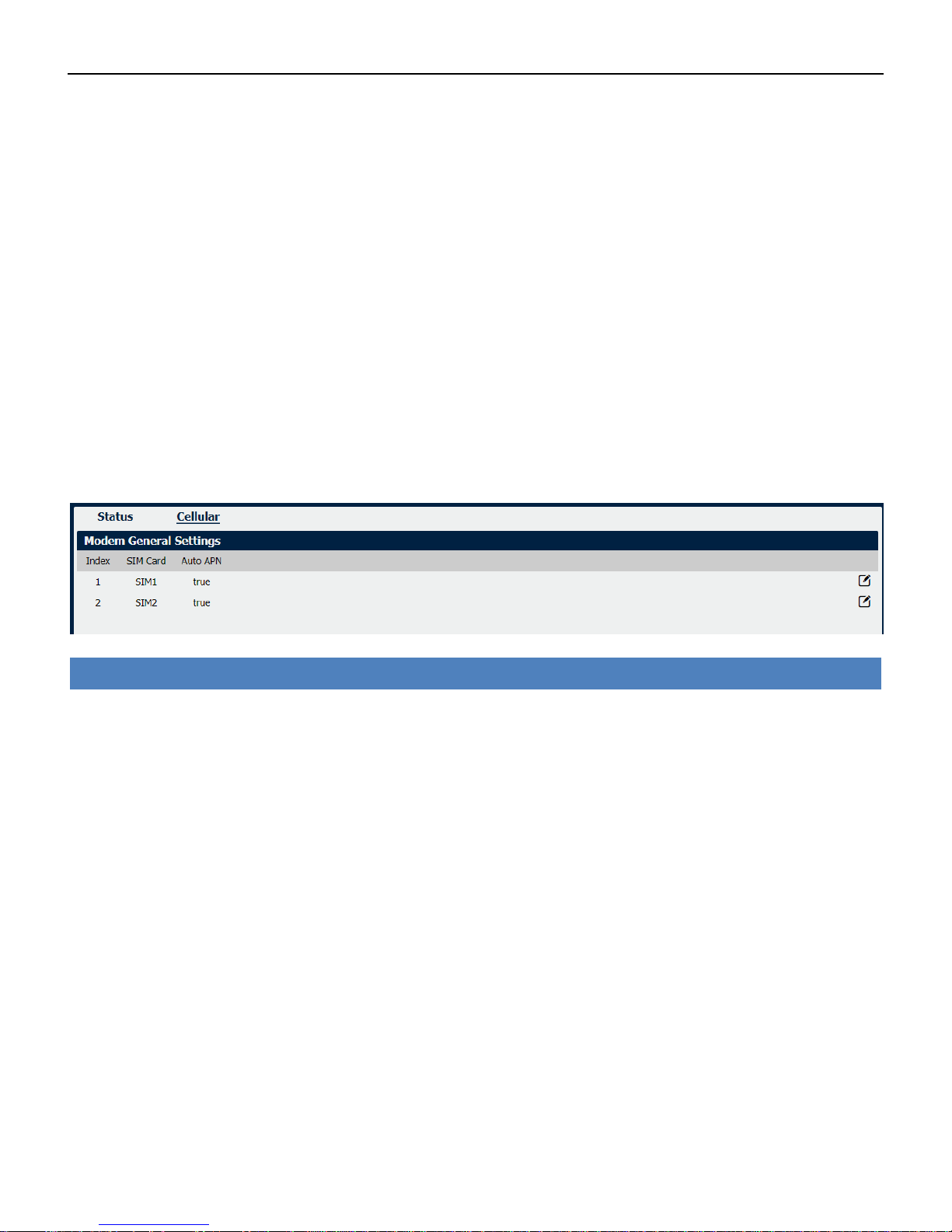
Cellular
• SIM Card
Displays the SIM card support on this unit.
• Auto APN
Displays the Enable status of auto APN function.
Industrial Cellular VPN Router NR500 Series User Manual
Page 33 / 78
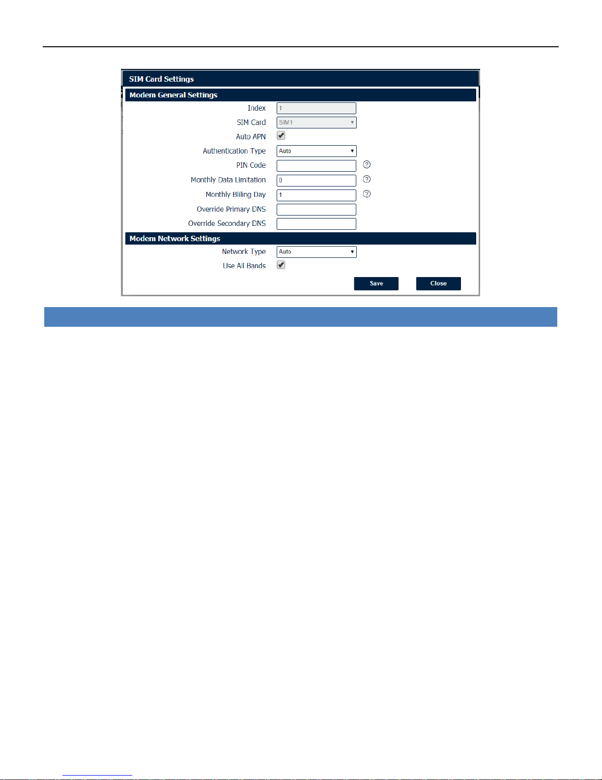
SIM Card Settings
• SIM Card
Displays the current SIM card settings.
• Auto APN
Check this box enable auto checking the Access Point Name provided by the carrier.
• Authentication Type
Authentication method used by the carrier. Possible selections are Auto, PAP, CHAP.
• PIN Code
Enter a 4-8 characters PIN code to unlock the SIM.
• Monthly Data Limitation
Enter the data total amount for SIM card, SIM card switchover when data reach limitation.
• Monthly Billing Day
Enter the date of renew data amount every month.
• Override Primary DNS
Enter the primary DNS server will override the automatically obtained DNS.
• Override Secondary DNS
Enter the secondary DNS server will override the automatically obtained DNS.
• Network Type
Select the mode of operation of the cell module (Auto, 4G Firstly, 4G Only, etc.).
• Use All Bands
Check this box to enable all bands selection or choose specified bands.
Industrial Cellular VPN Router NR500 Series User Manual
Page 34 / 78
4.3.3 Ethernet
The same instructions apply to settings for all Ethernet interfaces.
Displays the current IP address assigned to DHCP client.
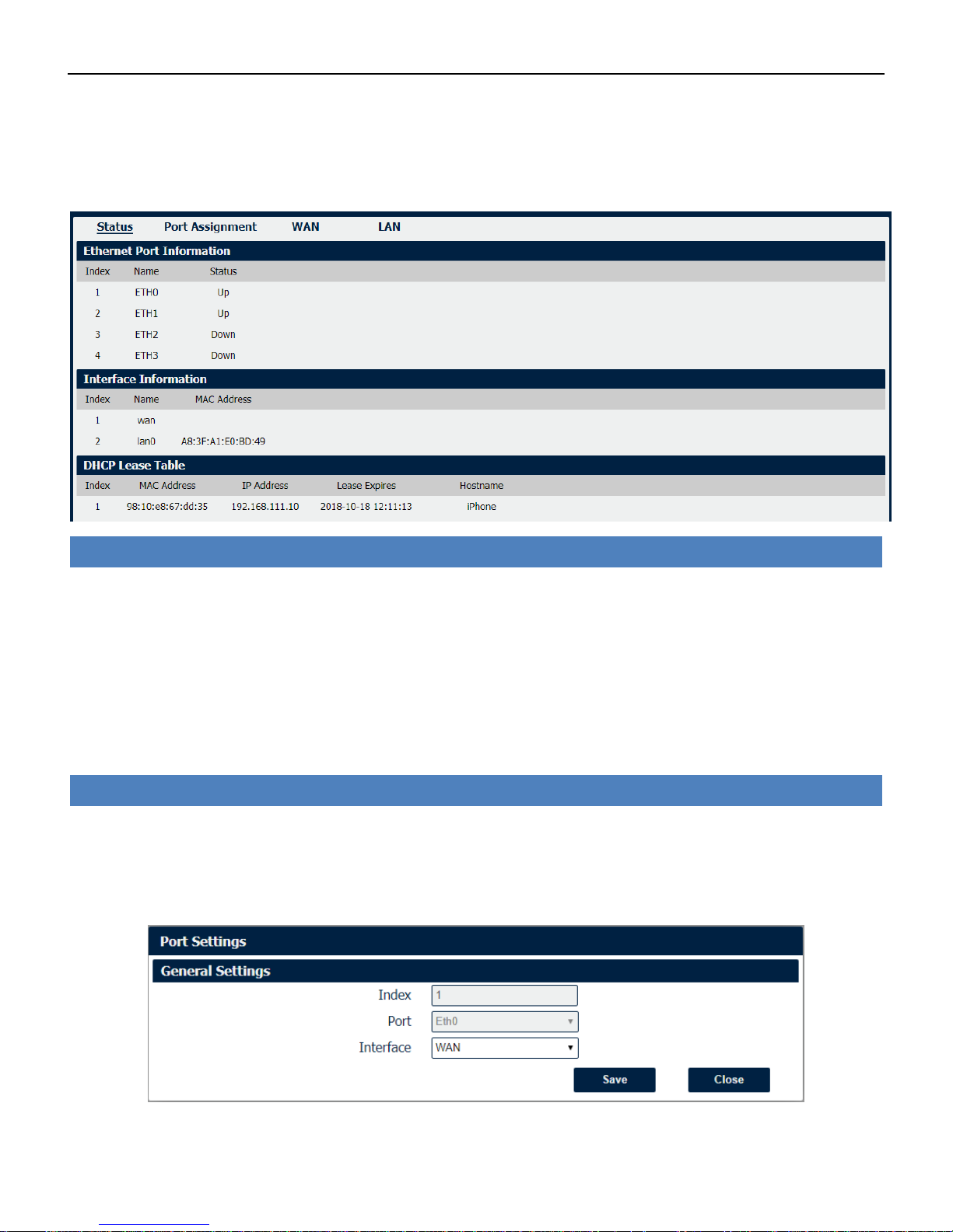
Ethernet->Status
• Ethernet Port Information
Displays the port physical connected states.
• Interface Information
Displays the name and MAC address of Ethernet interface.
• DHCP Lease Table
Ethernet->Port Assignment
• Port
Displays the port states and numbers of this unit.
• Interface
Displays the port states of belong subnet.

Industrial Cellular VPN Router NR500 Series User Manual
Page 35 / 78
Ethernet->Port Settings
• Port
Indicate the current configurate port.
• Interface
Select belong subnet for current configurate port.
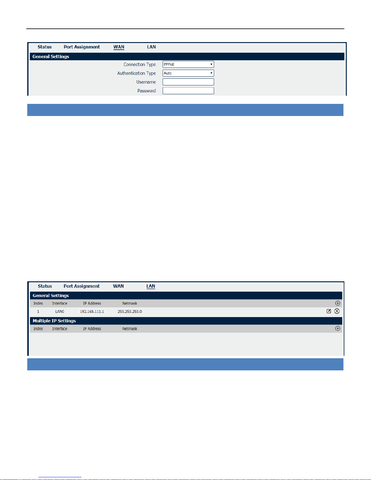
NR500 also support WAN connection type set to Static IP and PPPoE mode.
Ethernet->WAN
• Connection Type
If you select DHCP Client, external DHCP server will assign an IP address to this unit.
• NAT Enable
Enable or Disable NAT (Network Address Translation).
• MTU
Maximum Transmission Unit, maximum packet size allowed to be transmitted. Should be left as
default value of 1500 in most cases.
• Override Primary DNS
Enter the primary DNS server will override the automatically obtained DNS.
• Override Secondary DNS
Enter the secondary DNS server will override the automatically obtained DNS.
Industrial Cellular VPN Router NR500 Series User Manual
Page 36 / 78
Ethernet->WAN->Static IP or PPPoE
• IP Address
Static address for this interface. It must be on the same subnet as the gateway.
• Netmask
Will be assigned by the gateway.
• Gateway
IP address of the Gateway (DHCP Host). If not known this can be left as all zeros.
• Primary DNS
IP address of the primary DNS server.
• Secondary DNS
IP address of the secondary DNS server.
• Authentication Type
Authentication method used by the carrier. Possible selections are Auto, PAP, CHAP.
• Username
Username to provide when connecting.
• Password
Password to provide when connecting.
Ethernet->LAN
• Interface
Displays current name of LAN subnet.
• IP Address
Displays LAN IP address of this subnet.
• Netmask
Displays subnet mask for this subnet.

Industrial Cellular VPN Router NR500 Series User Manual
Page 37 / 78
Ethernet->LAN
• Interface
Select the configurate LAN port of this subnet.
• IP Address
Enter LAN IP address for this interface.
• Netmask
Enter subnet mask for this subnet.
• MTU
Maximum Transmission Unit, maximum packet size allowed to be transmitted. Should be left as
default value of 1500 in most cases.
• Enable
Check this box to enable DHCP feature on current LAN port.
• Mode
Select the DHCP working mode from “Server” or “Relay”.
Industrial Cellular VPN Router NR500 Series User Manual
Page 38 / 78
• Relay Server
Enter the IP address of DHCP relay server.
• IP Pool Start
External LAN devices connected to this unit will be assigned IP address in this range when DHCP is
enabled. This is the beginning of the pool of IP addresses.
• IP Pool End
This is the end of the pool of IP addresses.
• Netmask
Subnet mask of the IP address obtained by DHCP clients from DHCP server.
• Lease Time
The lease time of the IP address obtained by DHCP clients from DHCP server.
• Gateway
The gateway address obtained by DHCP clients from DHCP server.
• Primary DNS
Primary DNS server address obtained by DHCP clients from DHCP server.
• Secondary DNS
Secondary DNS server address obtained by DHCP clients from DHCP server.
• WINS Server
Windows Internet Naming Service obtained by DHCP clients from DHCP server.
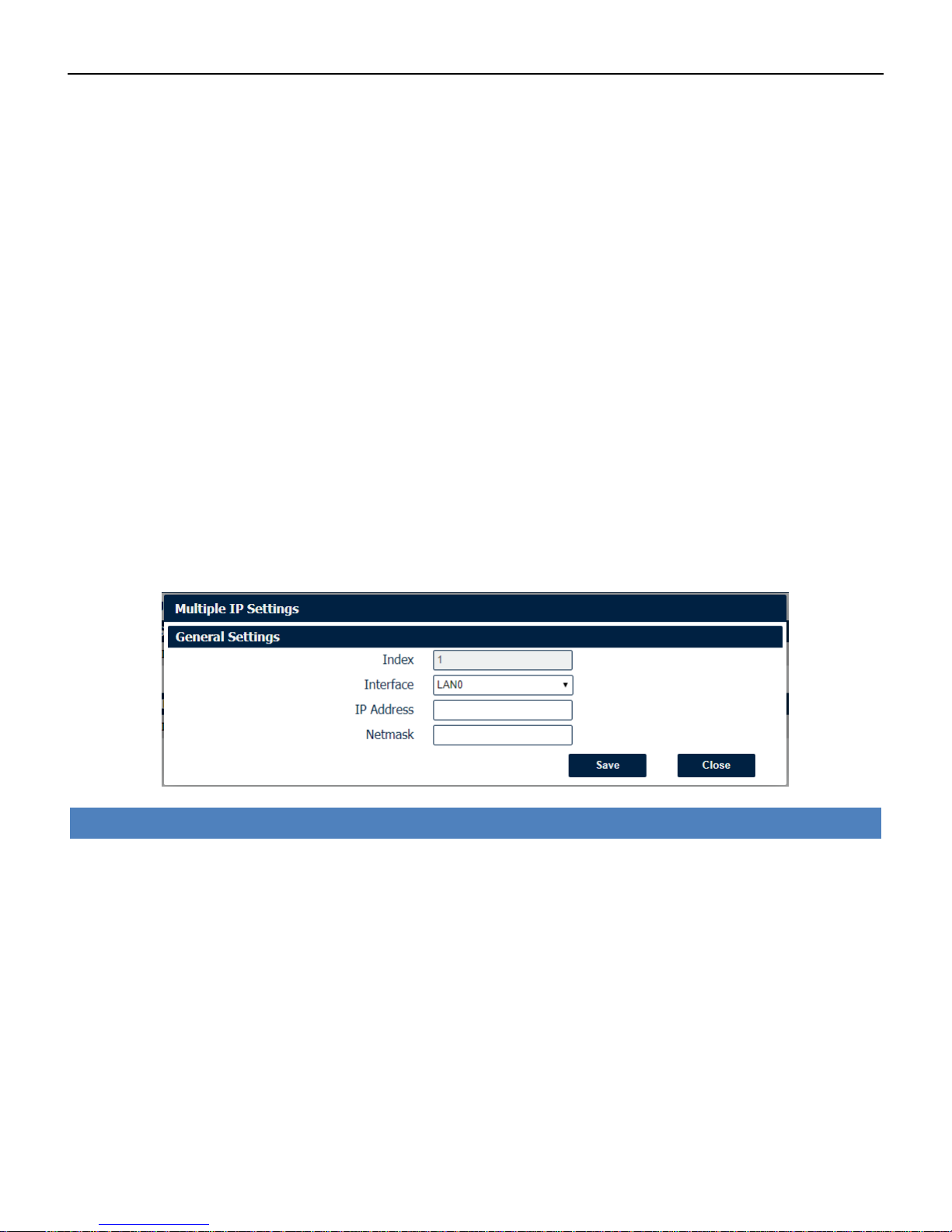
Ethernet->LAN->Multiple IP Settings
• Interface
Select the configurate LAN port of this subnet.
• IP Address
Enter multiple IP address for this interface.
• Netmask
Enter subnet mask for this subnet.
Industrial Cellular VPN Router NR500 Series User Manual
Page 39 / 78
4.3.4 Wi-Fi
NR500 router could only be set to function as either a Wi-Fi Client or a Wi-Fi Access Point, but not
both simultaneously. Select Wi-Fi (Access Point) from the main navigation menu to Wi-Fi (default
as Access Point) page, which contains tabs for configuration of the Wi-Fi Access Point interface.
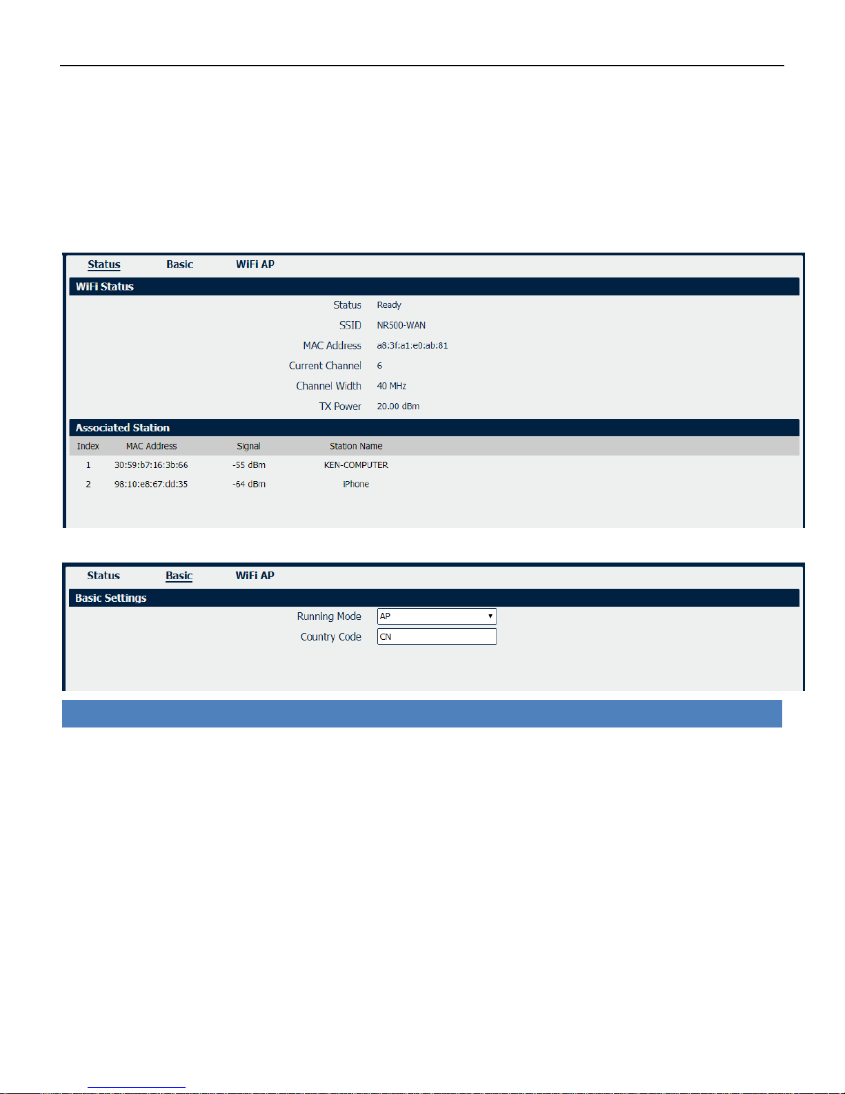
You could review the Wi-Fi connection status as below.
Wi-Fi->Basic
• Running Mode
Select the configurate Wi-Fi mode from AP or Client.
• Country Code
Enter the country where the AP is located.
Industrial Cellular VPN Router NR500 Series User Manual
Page 40 / 78
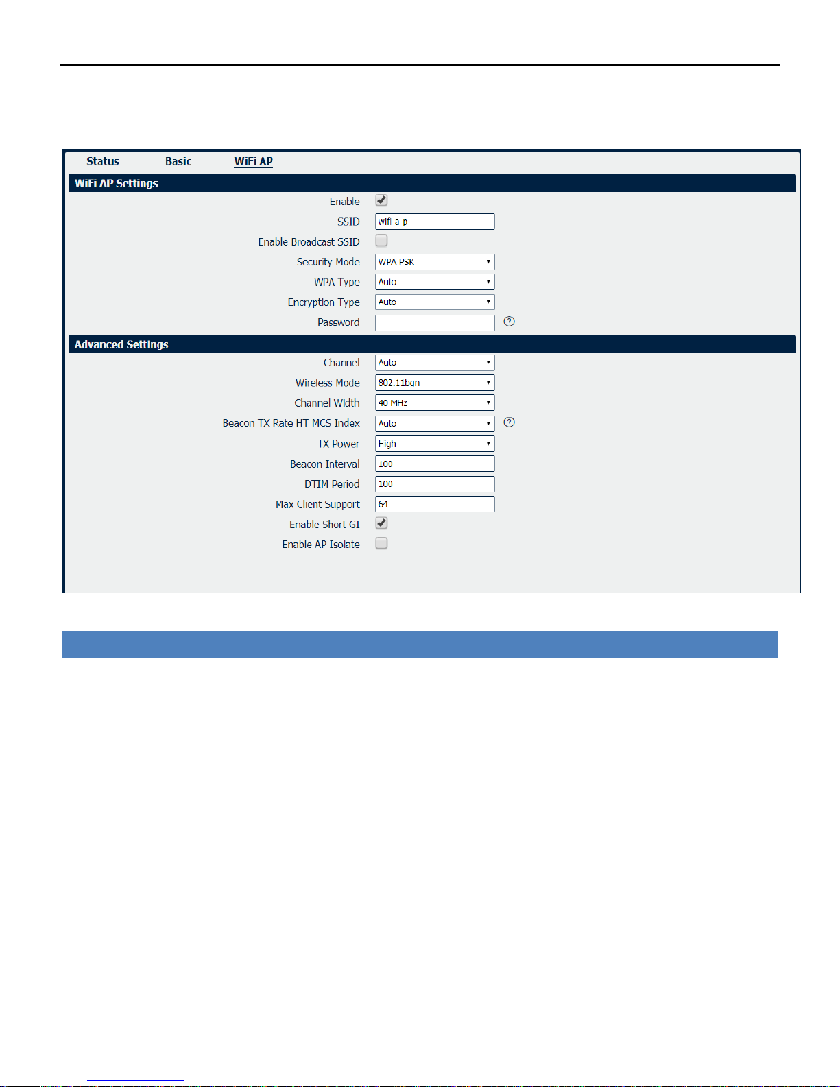
Wi-Fi AP
Wi-Fi AP settings page as below.
Wi-Fi->Wi-Fi AP
• Enable
Check this box will enable the Wireless interface.
• SSID
The SSID is the name of the wireless local network. Devices connecting to the Nr500 router WiFi
access will identify the Access Point by this SSID.
• Enable Broadcast SSID
When the checkbox is not checked, SSID broadcast is disabled, other wireless devices can't not find
the SSID, and users have to enter the SSID manually to access to the wireless network.
• Security Mode
Select security mode from “None” or “WPA PSK”.
• WPA Type
Select WPA Type from “Auto”,“WPA” and “WPA2”.
• Encryption Type
Select the encryption method. Options are “Auto”, “TKIP”, or “CCMP”. Because these options
depend on the authentication method selected, some options will not be available.
• Password
Enter the pre-shared key of WPA encryption.

Industrial Cellular VPN Router NR500 Series User Manual
Page 41 / 78
• Channel
Select the Wi-Fi channel the module will transmit on. If there are other Wi-Fi devices in the area the
NR500 router should be set to a different channel than the other access points. Channels available
for selection depend on the selected Band.
• Wireless Mode
Select the Wi-Fi 802.11 mode: B, G, or N. Available selections depend on selected Band.
• Channel Width
Select the width of the Wi-Fi channel. 20 MHz will limit the channel to 20 MHz wide; 20/40 MHz will
enable the use of a 40 MHz wide channel when available.
• Beacon TX Rate HT MCS Index
Modulation and Coding Scheme, The MCS modulation coding table is a representation proposed by
802.11n to characterize the communication rate of the WLAN. The MCS takes the factors affecting
the communication rate as the columns of the table and uses the MCS index as a row to form a rate
table.
• TX power
Select the transmission power for the AP from “High”, “Medium” and “Low”.
• Beacon Interval
Enter the interval of time in which the router AP broadcasts a beacon which is used for wireless
network authentication.
• DTIM Period
Enter the delivery traffic indication message period and the router AP will multicast the data
according to this period.
• Max Client Support
Enter the maximum number of clients to access when the router is configured as AP.
• Enable Short GI
Check this box to enable Short GI(guard interval), Short GI is a blank time between two symbols,
providing a long buffer time for signal delay.
• Enable AP Isolate
Check this box to enable AP isolate, the route will isolate all connected wireless devices.
Industrial Cellular VPN Router NR500 Series User Manual
Page 42 / 78
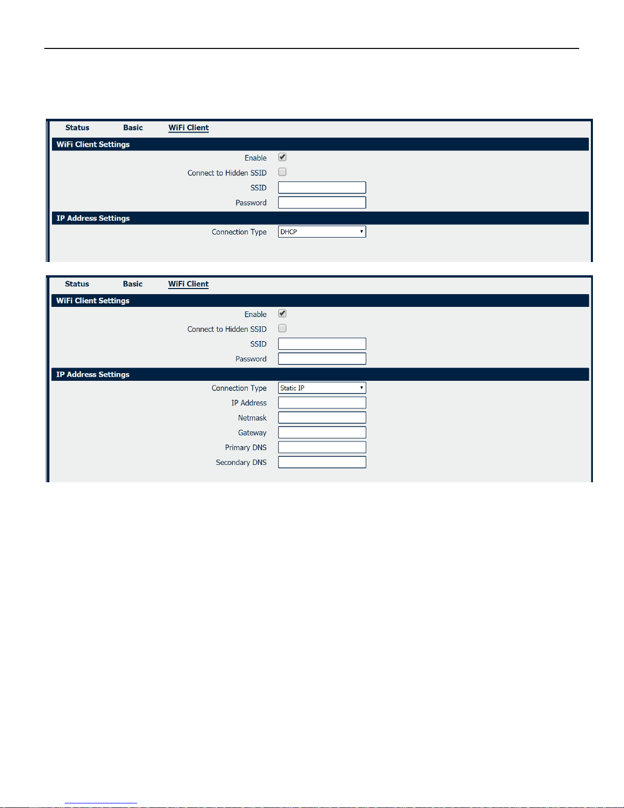
Wi-Fi Client
Wi-Fi Client settings page as below.

Industrial Cellular VPN Router NR500 Series User Manual
Page 43 / 78
Wi-Fi->Wi-Fi Client
• Enable
Check this box will enable the Wireless interface.
• Connect to Hidden SSID
Check this box will enable connect to hidden SSID.
• SSID
The SSID of external access point.
• Password
Enter the primary DNS server will override the automatically obtained DNS.
• Connection Type
Select from DHCP Client or Static IP address.
• IP Address
Static address for this interface. It must be on the same subnet as the gateway.
• Netmask
Will be assigned by the gateway.
• Gateway
IP address of the Gateway.
• Primary DNS
Enter the primary DNS server will override the automatically obtained DNS.
• Secondary DNS
Enter the secondary DNS server will override the automatically obtained DNS.

Industrial Cellular VPN Router NR500 Series User Manual
Page 44 / 78
4.4 Industrial Interface
The Industrial page contains tabs for making configuration settings for Serial RS232 and RS485,
Digital input and output. Select Serial & Digital IO from the main navigation menu to navigate to
this page.
4.4.1 Serial
You could review the status of serial connection.
Serial->Status
• Enable
Displays status of current serial function.
• Serial Type
Displays the serial type of COM port.
• Transmission Method
Displays the transmission method of this serial port.
• Protocol
Displays the protocol used by this serial port.
• Connection Status
Displays the connection status of this serial port.

Industrial Cellular VPN Router NR500 Series User Manual
Page 45 / 78
Serial->Connection
• Enable
Displays status of current serial function.
• Port
Displays the serial type of COM port.
• Baud Rate
Displays the serial port baud rate.
• Data Bits
Displays the serial port Data Bits.
• Stop Bits
Displays the serial port Stop Bits.
• Parity
Displays the serial port parity.

Industrial Cellular VPN Router NR500 Series User Manual
Page 46 / 78
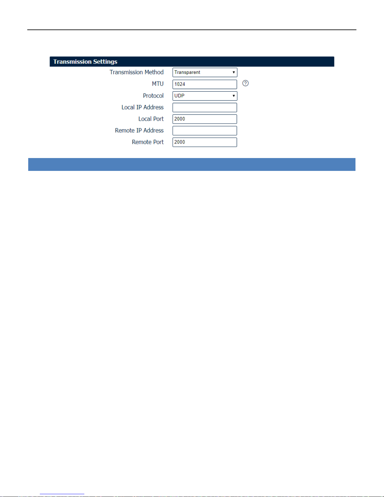
Serial->Connection Settings
• Baud Rate
Select the serial port baud rate. Supported values are 2400, 4800, 9600, 19200, 38400, 57600, or
115200.
• Data Bits
Select the values from 5, 6, 7 or 8.
• Stop Bits
Select the values from 1 or 2.
• Parity
Select values from none, even, odd.
• Transmission Method
Select the transmission method for serial port.
• MTU
Maximum Transmission Unit, maximum packet size allowed to be transmitted. Should be left as
default value of 1024 in most cases.
• Protocol
Select the mode for Serial IP communication. Supported modes are UDP, TCP Server, or TCP Client.
• Remote IP Address
Enter the IP address of the remote server.
• Remote Port
Enter the port number of the remote server.
Below window displays different settings when you select TCP Server on Protocol.
Serial->Connection Settings
• Local IP Address
Enter the IP Address of the local endpoint.
• Local Port
The port number assigned to the serial IP port on which communications will take place.
Industrial Cellular VPN Router NR500 Series User Manual
Page 47 / 78
Below window displays different settings when you select UDP on Protocol.
Serial->Connection Settings
• Local IP Address
Enter the IP Address of the local endpoint.
• Local Port
The port number assigned to the serial IP port on which communications will take place.
• Remote IP Address
Enter the IP address of the remote server.
• Remote Port
Enter the port number of the remote server.

Industrial Cellular VPN Router NR500 Series User Manual
Page 48 / 78
4.4.2 Digital IO
This section allows you to set the Digital IO parameters. The Digital input could be used for
triggering alarm, and Digital output could be used for controlling the slave device by digital
signal.
You could review the status of Digital IO as below.
Digital IO->Status
• Enable
Displays status of current digital IO function.
• Logic Level
Displays the electrical level of digital IO port.
• Status
Displays the alarm status of digital IO port.
Digital IO->Digital Input
• Enable
Check this box to enable digital Input function.
• Alarm ON Mode
Select the electrical level to trigger alarm. Option are “Low” and “High”.
Industrial Cellular VPN Router NR500 Series User Manual
Page 49 / 78
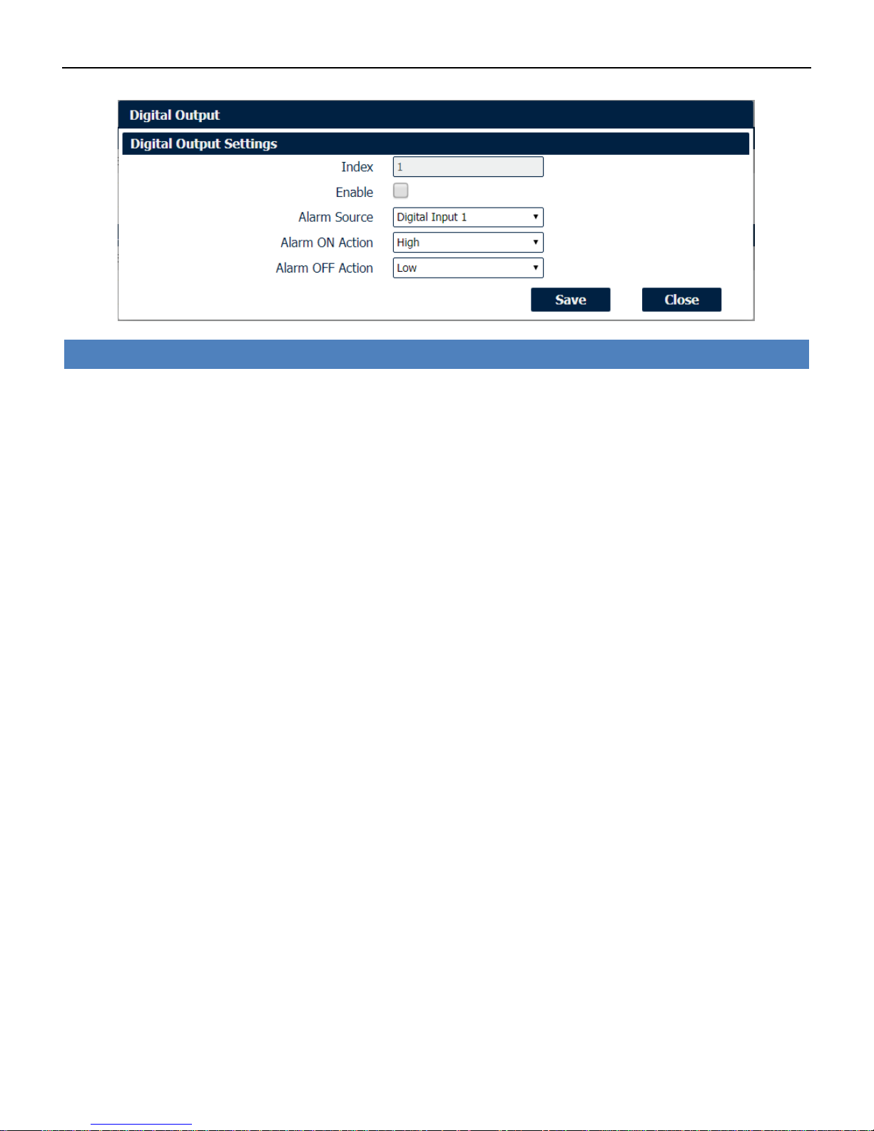
Digital IO->Digital Output
• Enable
Check this box to enable digital output function.
• Alarm Source
Select from “Digital Input1” or “Digital Input2”, Digital output triggers the related action when there is
alarm comes from Digital Input.
• Alarm ON Action
Select from “High”, “Low” or “Pulse”. High means high electrical level output. Low means low
electrical level output. Pulse will generate a square wave as specified in the pulse mode parameters
when triggered.
• Alarm OFF Action
Initiates when alarm disappeared. Select from “High”, “Low” or “Pulse”. High means high electrical
level output. Low means low electrical level output. Pulse will generate a square wave as specified in
the pulse mode parameters when triggered.
• Pulse Width
This parameter is available when select “Pulse” as “Alarm ON Action/Alarm OFF Action”. The
selected digital output channel will generate a square wave as specified in the pulse mode
parameters.

Industrial Cellular VPN Router NR500 Series User Manual
Page 50 / 78
4.5 Network
4.5.1 Firewall
Firewall rules are security rule-sets to implement control over users, applications or network objects
in an organization. Using the firewall rule, you can create blanket or specialized traffic transit rules
based on the requirement.
Firewall->ACL
• Default Policy
Select the “Accept” or “Drop” from the list, the packets which are not included in the access control list
will be processed by the default filter policy.
An access control list (ACL), with respect to a computer file system, is a list
of permissions attached to an object. An ACL specifies which users or system processes are
granted access to objects, as well as what operations are allowed on given objects.
Industrial Cellular VPN Router NR500 Series User Manual
Page 51 / 78
Firewall->ACL
• Description
Add a description for this rule.
• Protocol
Any: Any protocol number.
TCP: The TCP protocol.
UDP: The UDP protocol.
TCP & DUP: both TCP and UDP protocol
ICMP: The ICMP protocol.
• Source Address
A specific host IP address can also be specified, or a range of IP addresses via a bitmask (the box
following the /).
• Destination Address
A specific IP address can also be specified, or a range of IP addresses via a bitmask (the box
following the /).
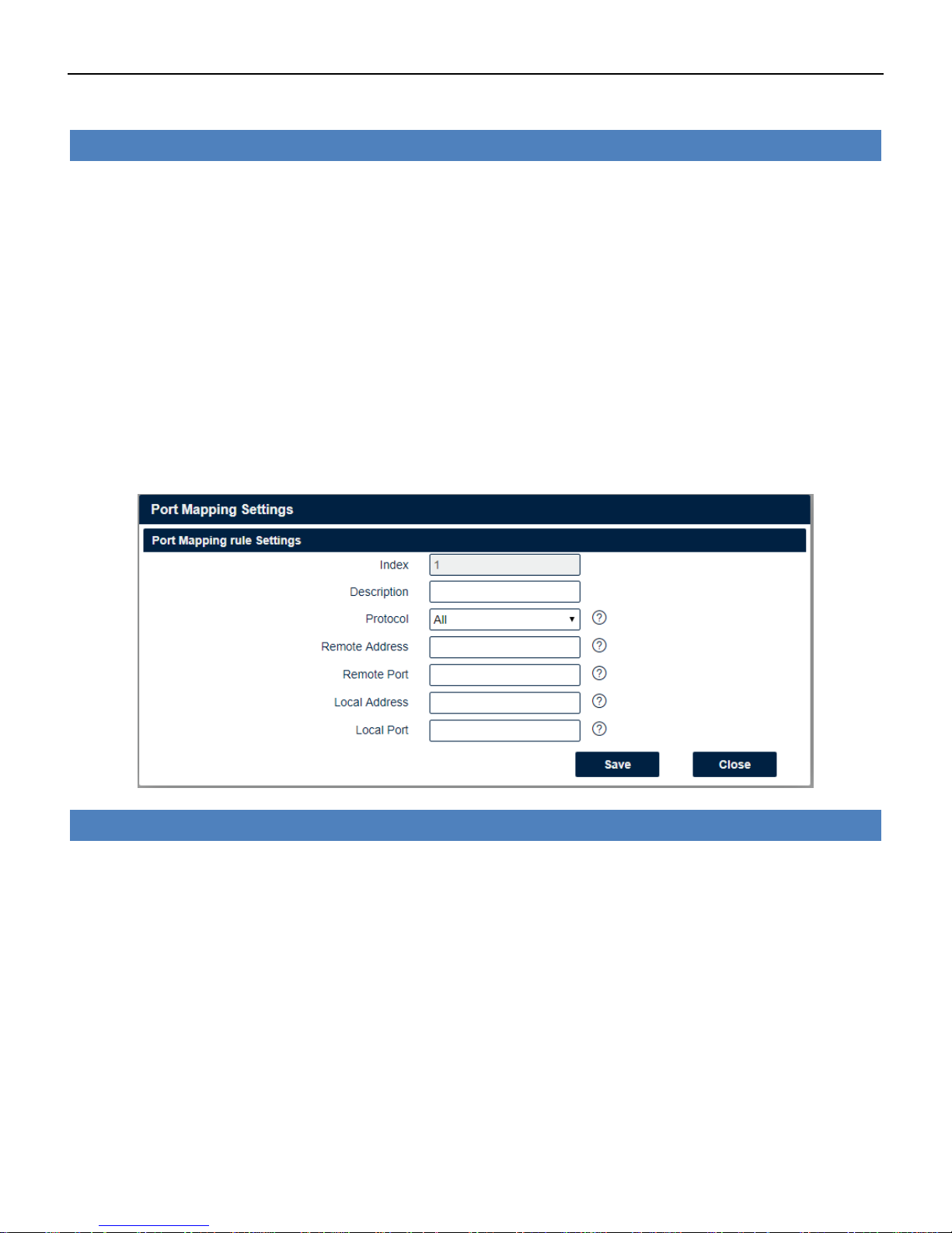
Firewall->Port Mapping
• Description
Add a description for this rule.
• Protocol
Any: Any protocol number.
TCP: The TCP protocol.
UDP: The UDP protocol.
• Remote Address
Enter a WAN IP address that is allowed to access the unit.
• Remote Port
Enter the external port number range for incoming requests.
• Local Address
Sets the LAN address of a device connected to one of the Fusion’s LAN interfaces. Inbound requests
will be forwarded to this IP address.

Industrial Cellular VPN Router NR500 Series User Manual
Page 52 / 78
• Local Port
Sets the LAN port number range used when forwarding to the destination IP address.
Firewall->DMZ
• Enable
Check this box to enable DMZ function.
• Remote Address
Optionally restricts DMZ access to only the specified WAN IP address.
NOTE: If set to 0.0.0.0, the DMZ is open to all incoming WAN IP addresses.
• DMZ Host Address
The WAN IP address which has all ports exposed except ports defined in the Port Forwarding
configuration.
4.5.2 Route
Static Routing refers to a manual method of setting up routing between networks. Select the
Static Routing tab to add static routes to the Static Route Table.
Please refer current route table as below.
Route->Route Table Information
• Destination
Displays the destination of routing traffic.
• Netmask
Displays the subnet mask of this routing.
• Gateway

Industrial Cellular VPN Router NR500 Series User Manual
Page 53 / 78
Displays the gateway of this interface. This is used for routing packets to remote networks.
• Interface
Displays the outbound interface of this route.
Route->Static Route Settings
• Description
Enter the description of current static route rule.
• IP Address
Enter the IP address of the destination network.
• Netmask
Enter the subnet mask of the destination network.
• Gateway
Enter the IP address of the local gateway.
• Interface
Please refer to the Network->Route->Status interface.
4.5.3 VRRP
The Virtual Router Redundancy Protocol (VRRP) is a computer networking protocol that provides
automatic assignment of available Internet Protocol (IP) routers for participating hosts. The VRRP
router who has the highest number will become the virtual master router. The VRRP router number
ranges from 1 to 255 and usually we use 255 for the highest priority and 100 for backup. If the
current virtual master router receives an announcement from a group member (Router ID) with a
higher priority, then the latter will pre-empt and become the virtual master router.
Industrial Cellular VPN Router NR500 Series User Manual
Page 54 / 78
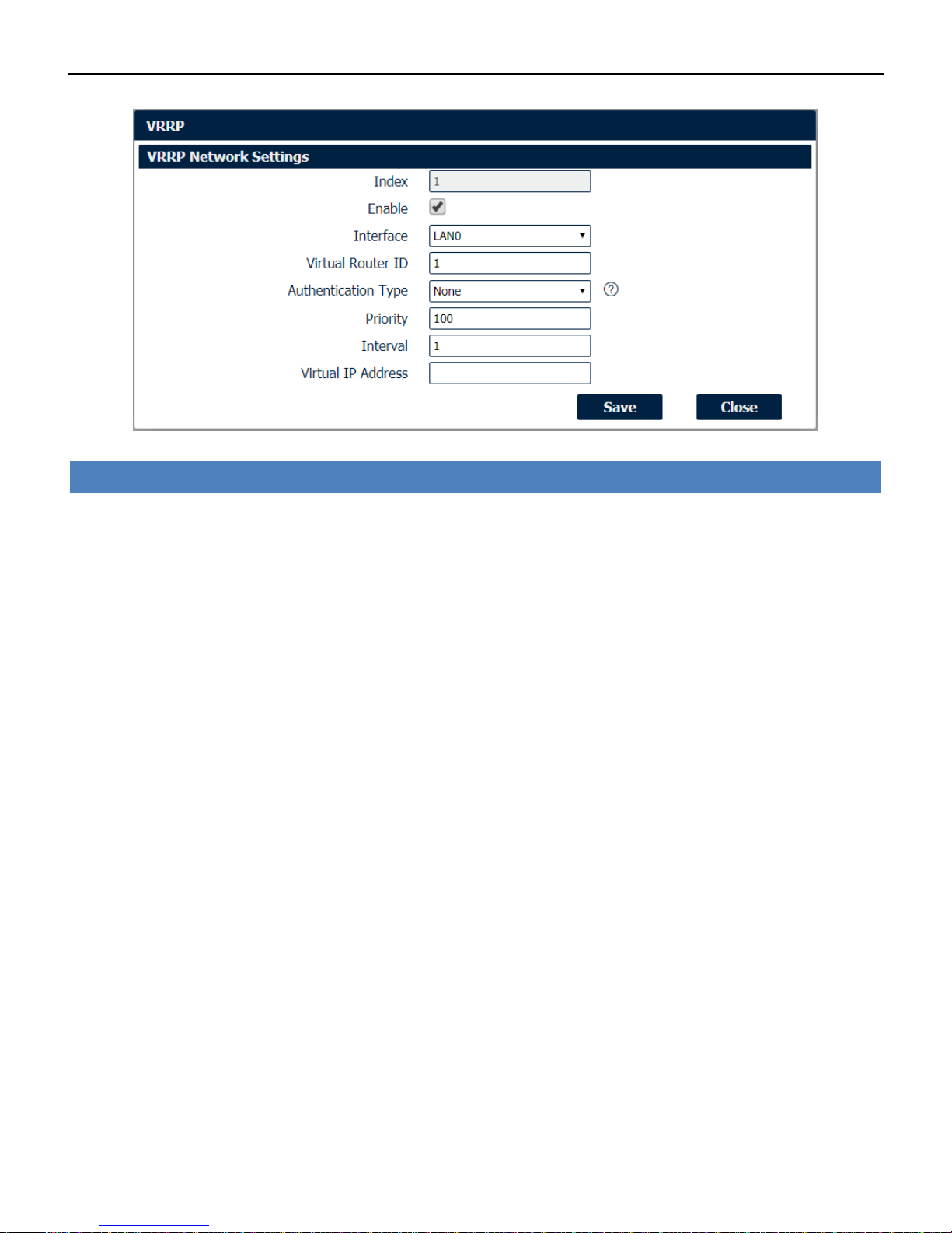
Network->VRRP
• Enable
Check this box will enable VRRP.
• Interface
Select the interface of Virtual Router.
• Virtual Router ID
User-defined Virtual Router ID. Range: 1-255.
• Authentication Type
Select the authentication type for VRRP.
• Priority
Enter the VRRP priority range is 1-254 (a bigger number indicates a higher priority).
• Interval
Heartbeat package transmission time interval between routers in the virtual IP group. Range: 1-255.
• Virtual IP Address
Enter the virtual IP address of virtual gateway.
Industrial Cellular VPN Router NR500 Series User Manual
Page 55 / 78
4.6 Applications
4.6.1 DDNS
DDNS is a system that allows the domain name data of a computer with a varying (dynamic) IP
addresses held in a name server to be updated in real time in order to make it possible to
establish connections to that machine without the need to track the actual IP addresses at all
times. A number of providers offer Dynamic DNS services (DDNS), free or for a charge.
You could review the status of DDNS as below.
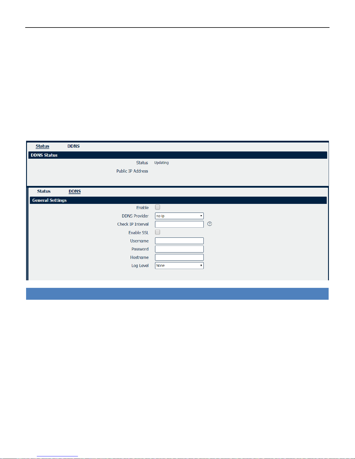
DDNS
• Enable
Check this box to enable the DDNS service.
• DDNS Provider
Select the DDNS provider from the list, options from “DynDNS”, “no-ip”,”3322” and custom.
• Check IP Interval
Enter the interval, in minutes (0 to 65,535), the modem will update the Dynamic DNS server of its
carrier assigned IP address.
• DDNS Server
The internet address to communicate the Dynamic DNS information to. This option is available after
you select custom on DDNS Provider.
• DDNS Path
DDNS path for custom type.
• Check IP Server
Check IP Server for custom type

Industrial Cellular VPN Router NR500 Series User Manual
Page 56 / 78
• Check IP Path
Check IP Path for custom type.
• Enable SSL
Enable SSL for connection.
• Username
Enter the user name used when setting up the account. Used to login to the Dynamic DNS service.
• Password
Enter the password associated with the account.
• Hostname
Enter the hostname associated with the account.
• Log Level
Select the log output level from “none”, “Debug”, “Notice”, ”Info” and “Error”.
4.6.2 Schedule Reboot
Schedule reboot allows user to define the time for router reboot itself.
Application->Schedule Reboot
• Enable
Check this box to enable schedule reboot feature.
• Time to Reboot
Enter the time of each day to reboot device. Format: HH(00-23):MM(00-59).
• Uptime
Enter the day of each month to reboot device. 0 means every day.
Industrial Cellular VPN Router NR500 Series User Manual
Page 57 / 78
4.7 VPN
4.7.1 OpenVPN
OpenVPN is an open source virtual private network (VPN) product that offers a simplified security
framework, modular network design, and cross-platform portability.
You could review all OpenVPN connection as below.
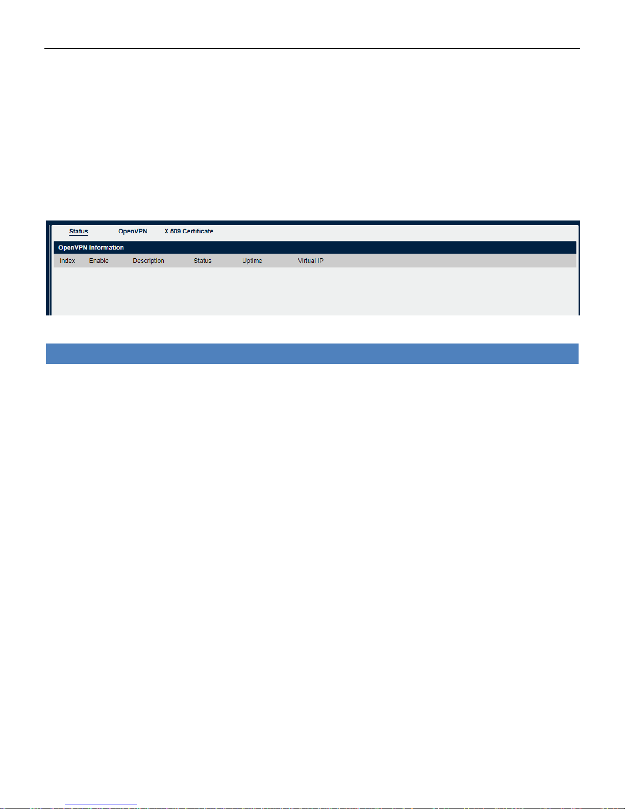
VPN->OpenVPN->Status
• Enable
Displays current OpenVPN settings is enable or disable.
• Status
Displays the current VPN connection status.
• Uptime
Displays the connection time since VPN is established.
• Virtual IP
Displays the virtual IP address obtain from remote side.
Industrial Cellular VPN Router NR500 Series User Manual
Page 58 / 78
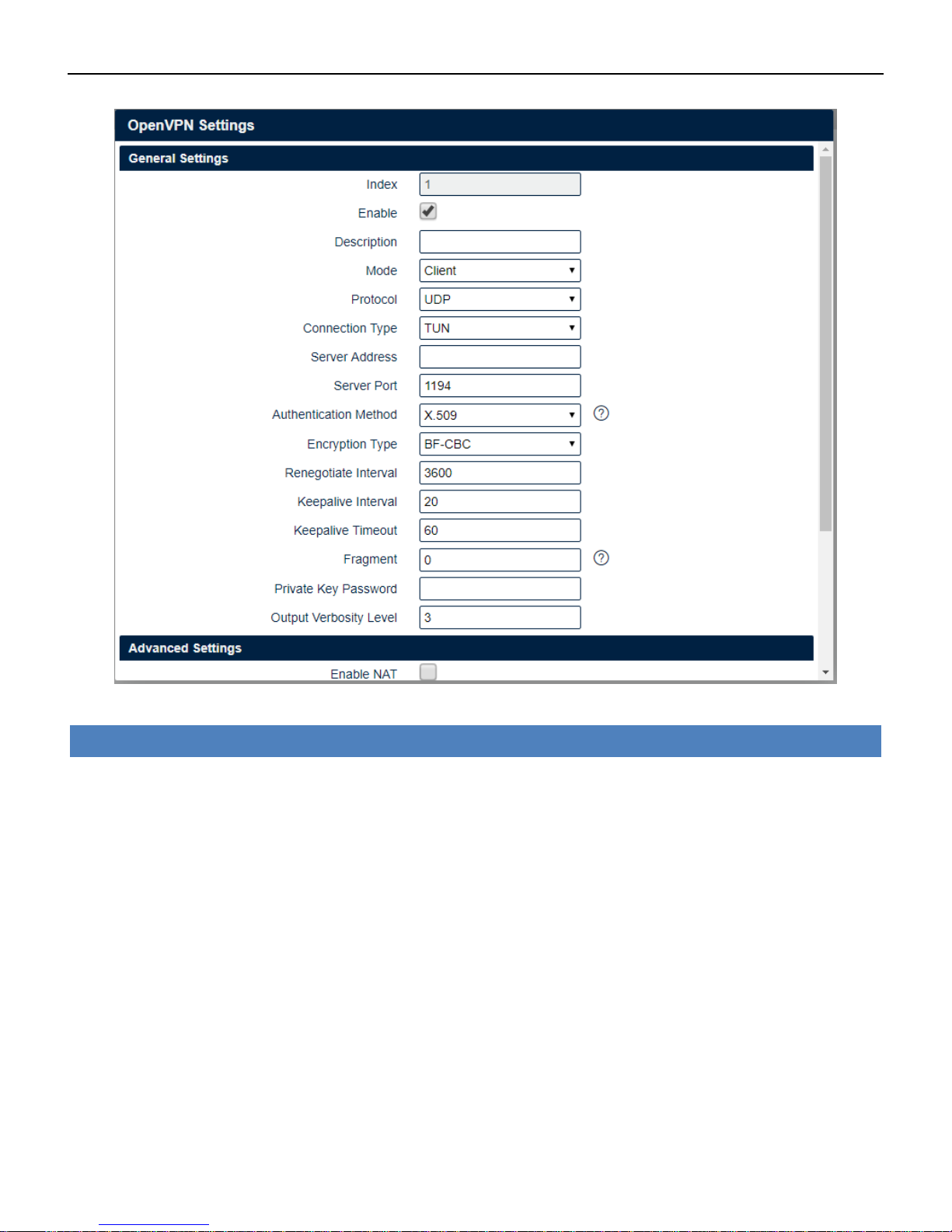
VPN->OpenVPN
• Enable
Check this box to enable OpenVPN tunnel.
• Description
Enter a description for this OpenVPN tunnel.
• Mode
Select from “Client” or “P2P”.
• Protocol
Select from “UDP” or “TCP Client”.
• Connection Type
Select from “TUN”, “TAP” which are two different kinds of device interface for OpenVPN. The
difference between TUN and TAP device is that a TUN device is a point-to-point virtual device on
network while a TAP device is a virtual device on Ethernet.
• Server Address
Enter the IP address or domain of remote server.
• Server Port
Enter the negotiate port on OpenVPN server.

Industrial Cellular VPN Router NR500 Series User Manual
Page 59 / 78
• Authentication Method
Select from "X.509", "Pre-shared", "Password", and "X.509 And Password".
• Encryption Type
Select from "BF-CBC", "DE-CBC", "DES-EDE3-CBC", "AES-128-CBC", "AES-192-CBC" and "AES-256-CBC".
• Username
Enter the username for authentication when selection from “Password” or “X.509 And Password”.
• Password
Enter the password for authentication when selection from “Password” or “X.509 And Password”.
• Local IP Address
Enter the local virtual IP address when select “P2P” mode.
• Remote IP Address
Enter the remote virtual IP address when select “P2P” mode.
• Local Netmask
Enter the local netmask when select “TAP” connection type.
• TAP Bridge
Select the specified LAN that bridge with OpenVPN tunnel when select “TAP” connection type.
• Renegotiate Interval
Enter the renegotiate interval if connection is failed.
• Keepalive Interval
Enter the keepalive interval to check the tunnel is active or not.
• Keepalive Timeout
Enter the keepalive timeout, once connection is failed it will trigger the OpenVPN reconnect.
• Fragment
Enter the fragment size, 0 means disable.
• Private Key Password
Enter the private key password for authentication when selection from “X.509” or “X.509 And
Password”.
• Output Verbosity Level
Enter the level of the output log and values.

Industrial Cellular VPN Router NR500 Series User Manual
Page 60 / 78
VPN->OpenVPN->Advanced Settings
• Enable NAT
Check this box to enable NAT, the source IP of host behind router will be disguised before accessing
the remote end.
• Enable PKCS#12
It is an exchange of digital certificate encryption standard, used to describe personal identity
information.
• Enable X.509 Attribute nsCertType
Require that peer certificate was signed with an explicit nsCertType designation of “server”.
• Enable HMAC Firewall
Add additional layer of HMAC authentication on the top of the TLS control channel to protect
against DoS attacks.
• Enable Compression LZO
Compress the data.
• Additional Configurations
Enter some other options of OpenVPN in this field. Each expression can be separated by a ‘;’.

Industrial Cellular VPN Router NR500 Series User Manual
Page 61 / 78
VPN->OpenVPN->X.509 Certificate
• Connection Index
Displays the current connection index for OpenVPN channel.
• CA Certificate
Import CA certificate file.
• Local Certificate File
Import Local Certificate file.
• Local Private Key
Import Local Private Key file.
• HMAC Firewall Key
Import HMAC Firewall Key file.
• Pre-shared Key
Import the pre-shared key file.
• PKCS#12 Certificate
Import PKCS#12 Certificate
Industrial Cellular VPN Router NR500 Series User Manual
Page 62 / 78
4.7.2 IPSec
IPSec facilitates configuration of secured communication tunnels. The various tunnel
configurations will be displayed in the Tunnel Table at the bottom of the page. All tunnels are
create using the ESP (Encapsulating Security Payload) protocol.
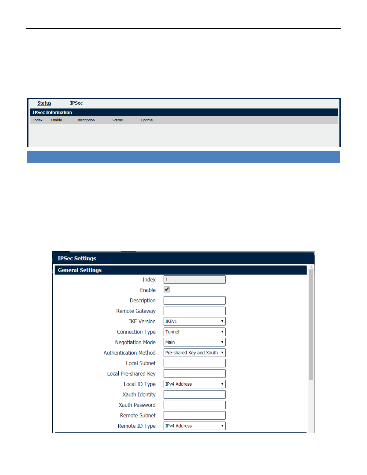
VPN->IPSec->Status
• Enable
Displays current IPSec settings is enable or disable.
• Description
Displays the description of current VPN channel.
• Status
Displays the current VPN connection status.
• Uptime
Displays the connection time since VPN is established.

Industrial Cellular VPN Router NR500 Series User Manual
Page 63 / 78
VPN->IPSec
• Enable
Select Enable will launch the IPSec process.
• Description
Enter a description for this IPSec VPN tunnel.
• Remote Gateway
Enter the IP address of the remote endpoint of the tunnel.
• IKE Version
Internet Key Exchange, select from “IKEv1” or “IKEv2”.
• Connection Type
Select from “Tunnel” or “Transport”.
Tunnel: In tunnel mode, the entire IP packet is encrypted and authenticated. It is then encapsulated
into a new IP packet with a new IP header. Tunnel mode is used to create virtual private networks for
network-to-network communications.
Transport: In transport mode, only the payload of the IP packet is usually encrypted or authenticated.
The routing is intact, since the IP header is neither modified nor encrypted.
• Negotiation Mode
Select from “Main” or “Aggressive”.
• Authentication Method
Select from “Pre-shared Key” or “Pre-shared Key and Xauth”.
• Local Subnet
Ener the IP address with mask if a network beyond the local LAN will be sending packets through the
tunnel.
NOTE: The Remote subnet and Local subnet addresses must not overlap!
• Local Pre-shared Key
Enter the pre-shared key which match the remote endpoint.
• Local ID Type
The local endpoint's identification. The identifier can be a host name or an IP address.
• Xauth Identity
Enter Xauth identity after “Pre-shared Key and Xauth” on authentication Method is enabled.
• Xauth Password
Enter Xauth password “Pre-shared Key and Xauth” on authentication Method is enabled.
• Remote Subnet
Enter an IP address with mask if encrypted packets are also destined for the specified network that is
beyond the Remote IP Address.
NOTE: The Remote subnet and Local subnet addresses must not overlap!
• Remote ID Type
The authentication address of the remote endpoint.

Industrial Cellular VPN Router NR500 Series User Manual
Page 64 / 78
VPN->IPSec
• Encryption Algorithm (IKE)
Select 3DES AES-128, AES-192, or AES-256 encryption.
• Hash Algorithm (IKE)
Select from MD5, SHA1, SHA2 256, SHA2 384 or SHA2 512 hashing.
• Diffie-Hellman Group (IKE)
Negotiate (None) or use 768 (Group 1), 1024 (Group 2), 1536 (Group 5) or 2048 (Group 14) etc.
• Lifetime (IKE)
How long the keying channel of a connection should last before being renegotiated.
• Encryption Algorithm (ESP)
Select 3DES AES-128, AES-192, or AES-256 encryption.
• Hash Algorithm (ESP)
Select from MD5, SHA1, SHA2 256, SHA2 384 or SHA2 512 hashing.
• Diffie-Hellman Group (ESP)
Negotiate (None) or use 768 (Group 1), 1024 (Group 2), 1536 (Group 5) or 2048 (Group 14) etc.
• Lifetime (ESP)
How long a particular instance of a connection should last, from successful negotiation to expiry.
• DPD Interval
Enter the interval after which DPD is triggered if no IPsec protected packets is received from the peer.
• DPD Timeout
Enter the remote peer probe response timer.
• Additional Configurations
Enter some other options of IPSec in this field. Each expression can be separated by a ‘;’.
Industrial Cellular VPN Router NR500 Series User Manual
Page 65 / 78
4.7.3 GRE
Generic Routing Encapsulation (GRE) is a protocol that encapsulates packets in order to route
other protocols over IP networks. It’s a tunneling technology that provides a channel through
which encapsulated data message could be transmitted and encapsulation and decapsulation
could be realized at both ends.
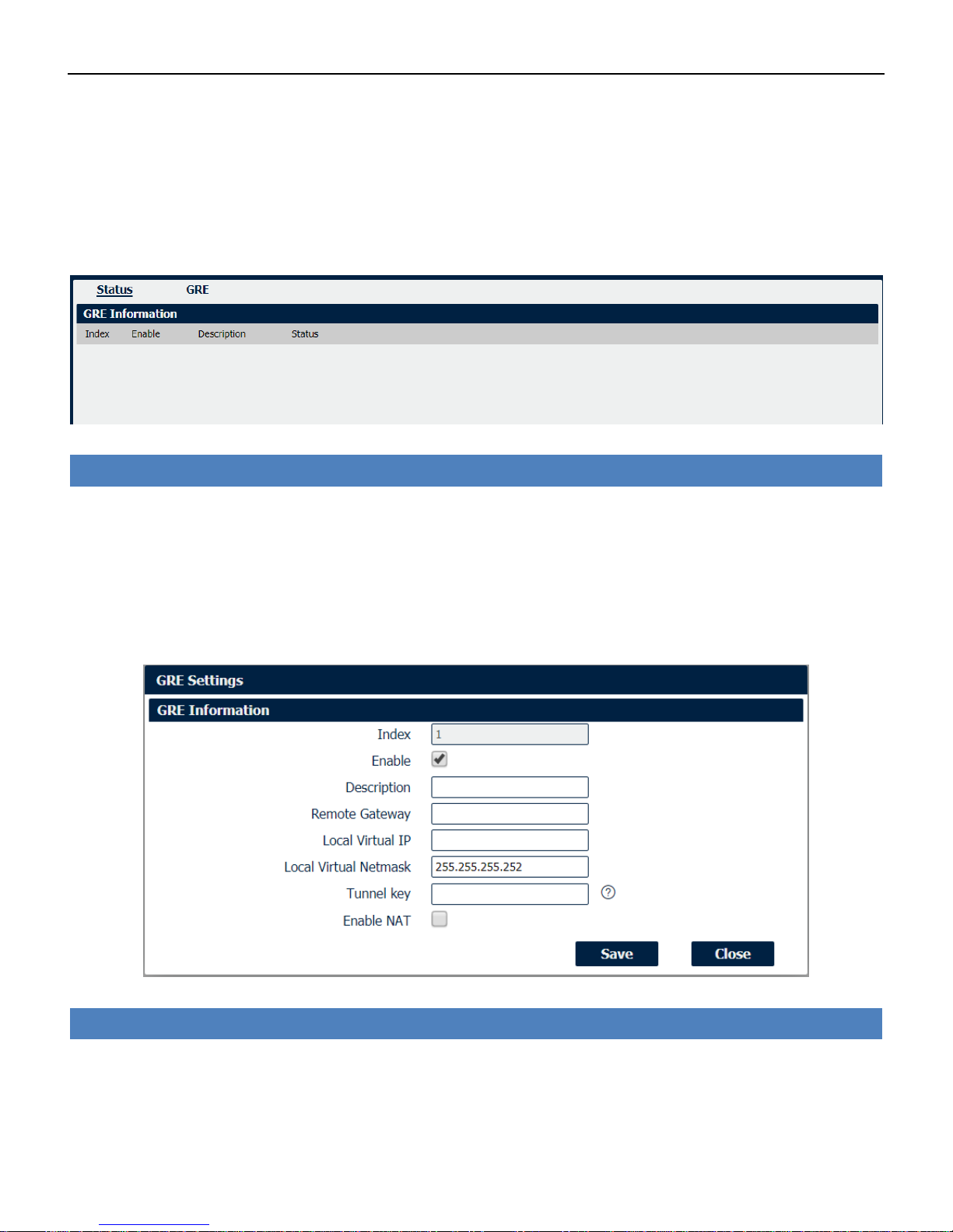
VPN->GRE->Status
• Enable
Displays current GRE settings is enable or disable.
• Description
Displays the description of current VPN channel.
• Status
Displays the current VPN connection status.
VPN->GRE
• Enable
Check this box to enable GRE.
• Description
Enter the description of current VPN channel.

Industrial Cellular VPN Router NR500 Series User Manual
Page 66 / 78
• Remote Gateway
Enter the remote IP address of peer GRE tunnel.
• Local Virtual IP
Enter the local tunnel IP address of GRE tunnel.
• Local Virtual Netmask
Enter the local virtual netmask of GRE tunnel.
• Tunnel Key
Enter the authentication key of GRE tunnel.
• Enable NAT
Check this box to enable NAT function.
4.8 Maintenance
4.8.1 Upgrade
When newer versions of NR500 firmware become available, the user can manually update the
unit by uploading a package to the unit.
NOTE: The unit automatically reboots once the upload completes, thus taking the NR500 router
out of service during approximately 1 minute. Unless otherwise stated, the user is not expected to
take any special precautions.
CAUTION: It is important to have a stable power source and ensure that power to the Fusion is not
interrupted during a firmware upgrade.

Industrial Cellular VPN Router NR500 Series User Manual
Page 67 / 78
4.8.2 System
This section allows you to review the device system settings.
System->General
• Hostname
User-defined router name, which might be use for IPSec local ID identify.
• User LED Type
Defined the User LED behavior.
• Time Zone
Select the zone where the device is in use.
• Customized Time Zone
Customized the zone where the device is in use.
• Enable (NTP Client)
Selected Enabled to utilize the NTP client to synchronize the device clock over the network using a
time server (NTP server).
• Primary NTP Server
Enter the IP address (or host name) of the primary time server.
• Secondary NTP Server
Enter the IP address (or host name) of the secondary time server.
Industrial Cellular VPN Router NR500 Series User Manual
Page 68 / 78
System->Account
• Administrator
Displays the name of current administrator, default as “admin”.
• Old Password
Enter the old password of administrator.
• New Password
Enter the new password of administrator.
• Confirm Password
Confirm the new password of administrator.
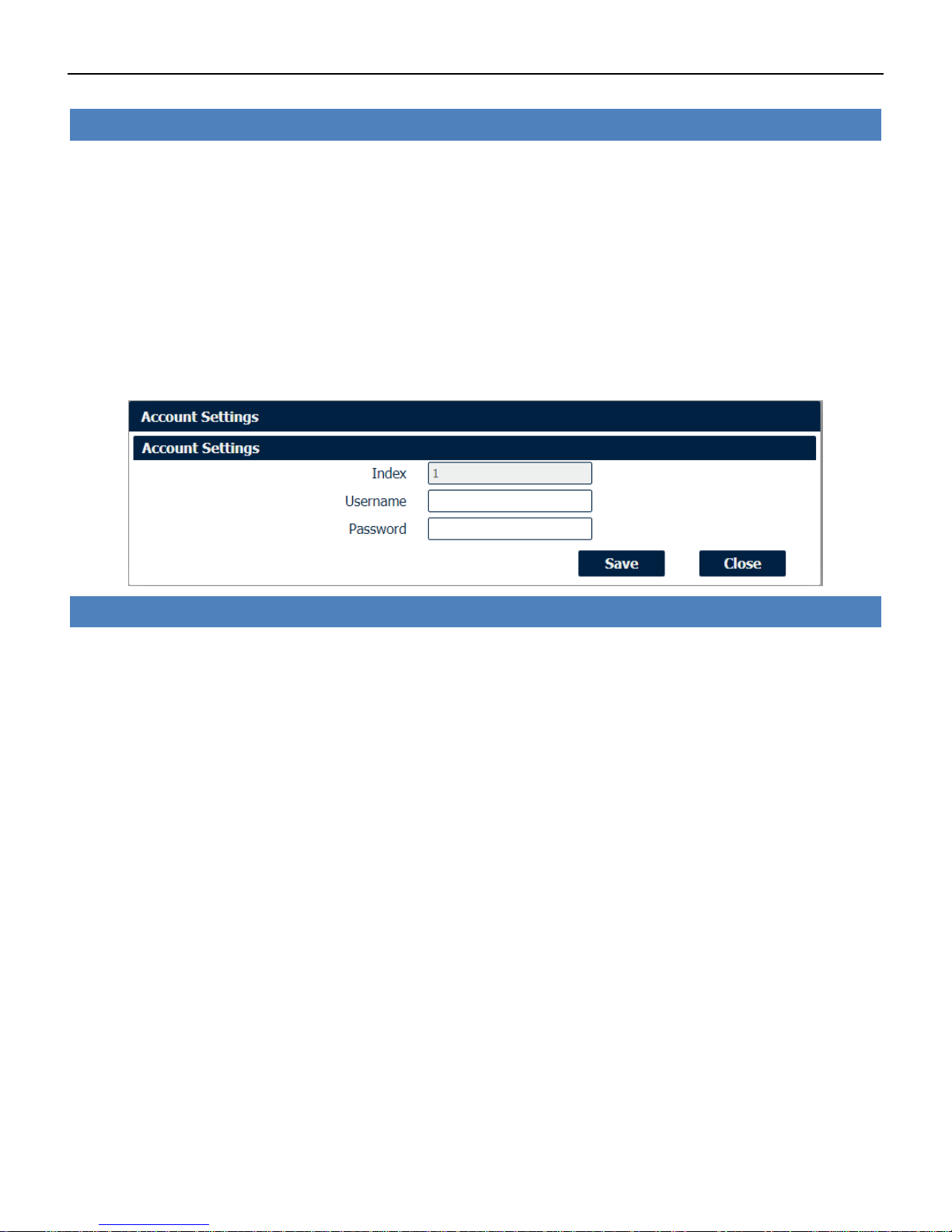
System->Account
• Username
Enter a username of visitor privilege
• Password
Enter the new password of current visitor account.
Industrial Cellular VPN Router NR500 Series User Manual
Page 69 / 78
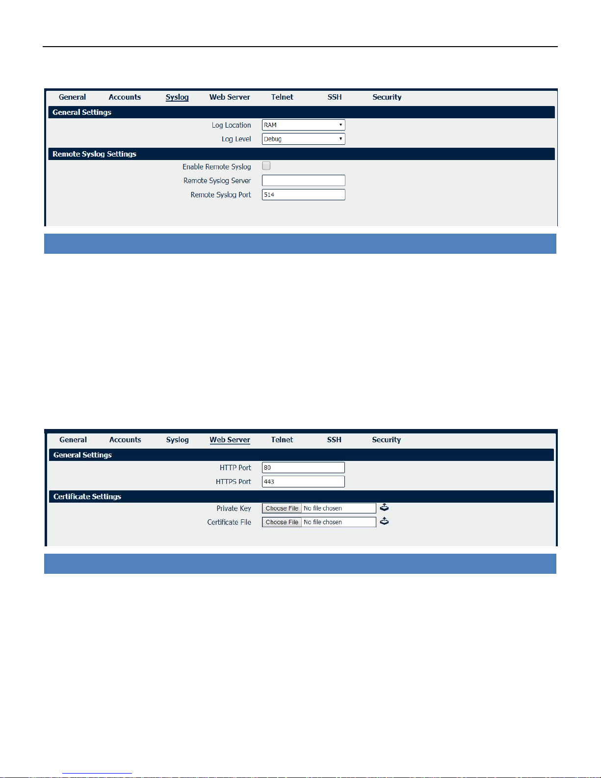
Syslog displays system logs that are stored in the log buffers.
System->Syslog
• Log Location
Select the log store location from “RAM” or “Flash”.
• Log Level
Select the log output level from “Debug”, “Notice”, “Info”, “Warning” or “Error”.
• Enable Remote Syslog
Check this box to enable remote syslog connection.
• Remote Syslog Server
Enter the IP address of remote syslog server.
• Remote Syslog Port
Enter the port for remote syslog server listening.
System->Web Server
• HTTP Port
Enter the port for Hypertext Transfer Protocol. A well-known port for HTTP is port 80.
• HTTPS Port
Enter the port for HTTPS Protocol. A well-known port for HTTPS is port 443.
• Private Key
Import private Key file for HTTPS connection.
• Certificate File
Import certificate file for HTTPS connection.
Industrial Cellular VPN Router NR500 Series User Manual
Page 70 / 78
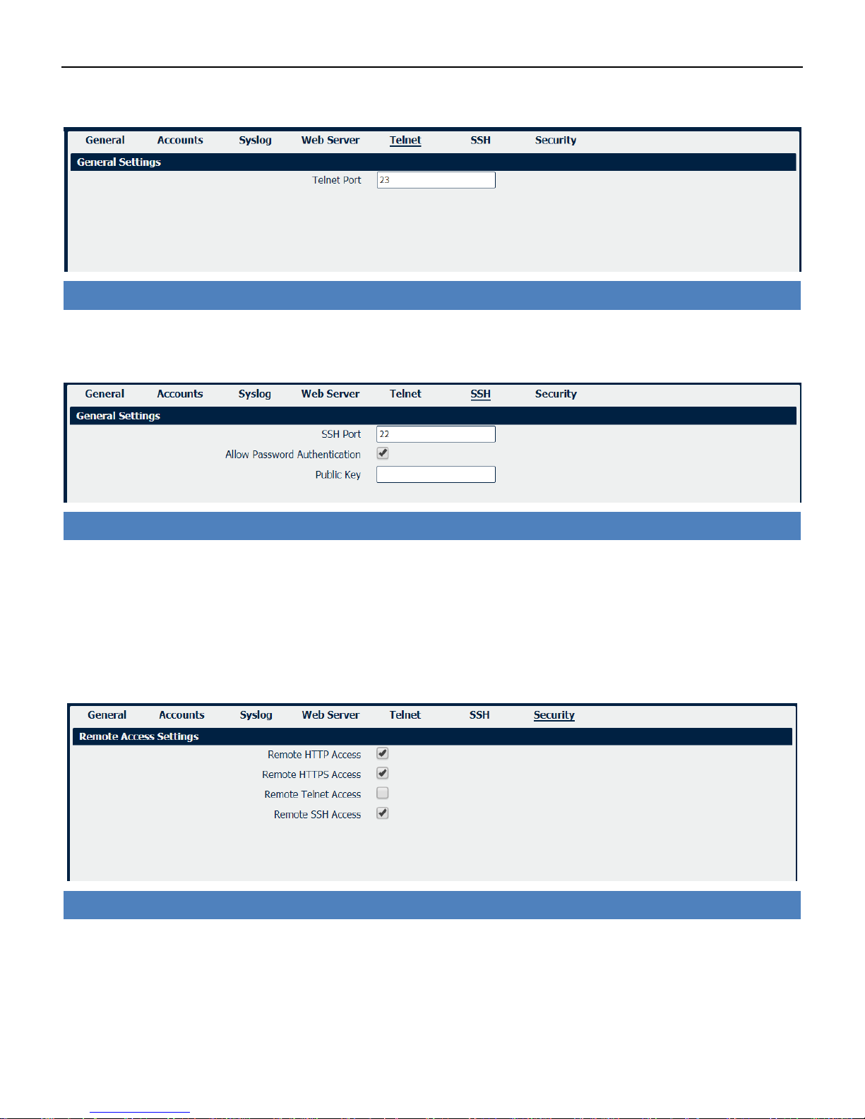
System->Telnet
• Telnet Port
Enter the port for telnet access. A well-known port for HTTP is port 23.
System->SSH
• SSH Port
Enter the port for SSH access. A well-known port for HTTP is port 22.
• Allow Password Authentication
Check this box to enable SSH authentication.
• Public Key
Enter the public Key SSH authentication.
System->Security
• Remote HTTP Access
Check this box to allow remote HTTP access.
• Remote HTTPS Access
Check this box to allow remote HTTPS access.
• Remote Telnet Access
Industrial Cellular VPN Router NR500 Series User Manual
Page 71 / 78
Check this box to allow remote Telnet access.
• Remote SSH Access
Check this box to allow remote SSH access.
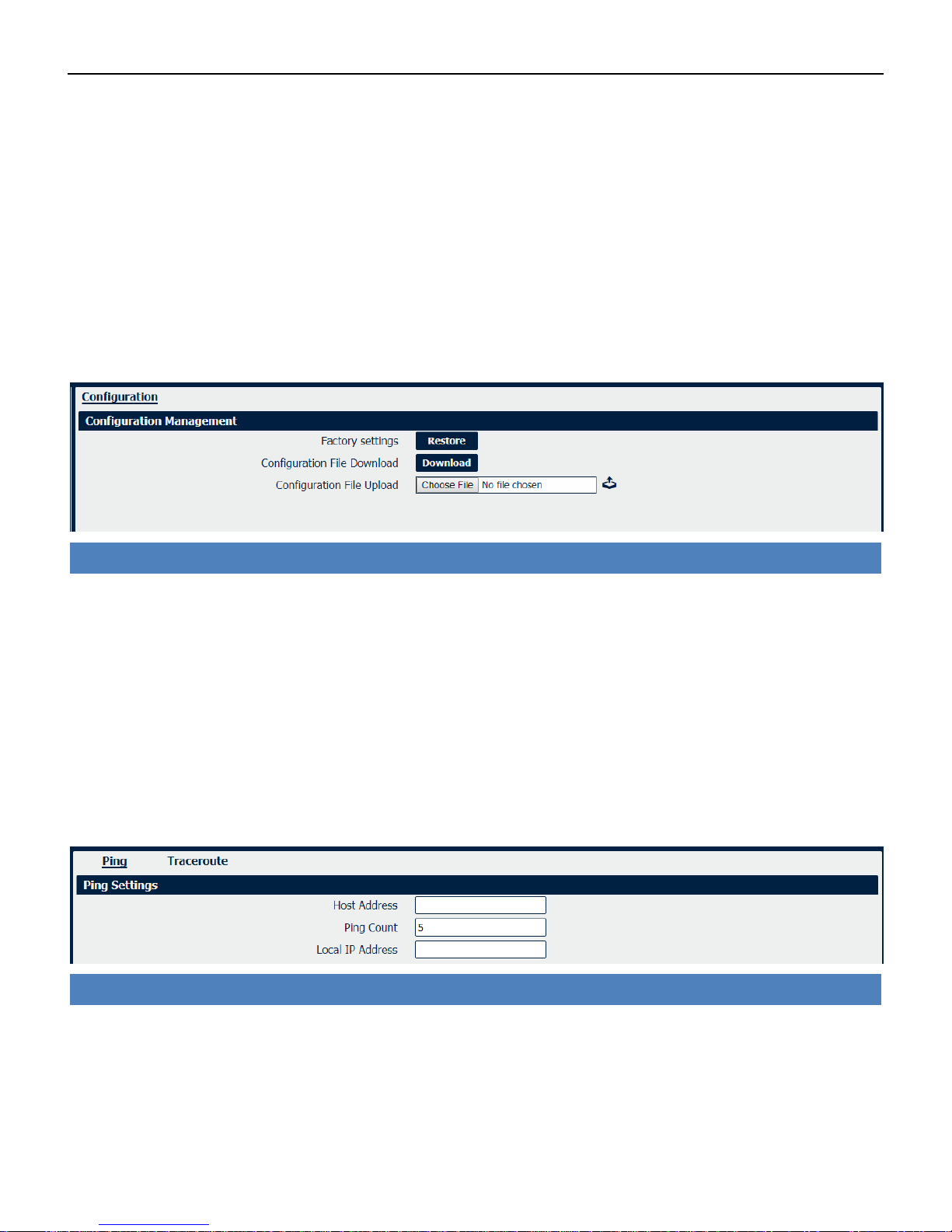
4.8.3 Configuration
The Unit Configuration tab allows you to save parameters (settings in the Web interface) to a file.
Conversely, if you have saved settings from the NR500 router to a file, you can Import these
previously-saved configuration settings to the NR500 router as well.
System->Configuration
• Restore
Reset the unit to factory default settings.
• Download
Download the configuration file from NR500 router.
• Configuration File Upload
Import previously-saved configuration file.
4.8.4 Debug Tools
Debug Tools->Ping
• Host Address
Enter a host IP address or domain name for ping.
• Ping Count
Enter the ping times.
• Local IP Address
Enter the ping source IP address or leave it blank.

Industrial Cellular VPN Router NR500 Series User Manual
Page 72 / 78
Debug Tools->Traceroute
• Host Address
Enter a host IP address or domain name for traceroute.
• Max Hops
Enter the max hops for traceroute.

Industrial Cellular VPN Router NR500 Series User Manual
Page 73 / 78
Appendix A -Glossary
APN:
Access Point Name
GPRS:
General Packet Radio Service
HSPA:
High Speed Packet Access
HSDPA:
High-Speed Downlink Packet Access
HSUPA:
High-Speed Uplink Packet Access
LTE:
3GPP Long Term Evolution
IMEI:
International Mobile Equipment Identity
ICCID:
Integrated Circuit Card Identifier
PIN:
Personal Identification Number
PPP:
Point-to-Point Protocol
RSSI:
Received Signal Strength Indication
SIM:
Subscriber Identity Module
SMS:
Short Message Service
DHCP:
Dynamic Host Configuration Protocol
LAN:
Local Area Network
LED:
Light-Emitting Diode
NTP:
Network Time Protocol
SMA:
SubMiniature version A (connector)
SSID:
Service Set Identifier
TCP/IP:
Transmission Control Protocol / Internet Protocol
UDP:
User Datagram Protocol
VPN:
Virtual Private Network
Wi-Fi or WiFi:
Wireless Fidelity
VDC:
Voltage, Direct Current

Industrial Cellular VPN Router NR500 Series User Manual
Page 74 / 78
Appendix B -Q&A
No Signal
Phenomenon
NR500 Router modem status show no signal.
Possible Reason
• Antenna installation is wrong.
• Modem failure.
Solution
• Check the LTE antenna or replace with new one.
• Check the cellular page confirm modem is detected correctly or not.
Cannot detect SIM card
Phenomenon
NR500 Router cannot detect SIM card, cellular is not failed to connect to base station.
Possible Reason
• SIM card damage.
• SIM bad contact.
Solution
• Replace SIM card.
• Re-install SIM card.
Poor Signal
Phenomenon
NR500 Router no signal or poor signal.
Possible Reason
• Antenna installation is wrong.
• Area signal weak.
Solution
• Check the antenna and re-connect it.
• Contact Telecom Operator to confirm signal problem.
• Change to high-gain antenna.

Industrial Cellular VPN Router NR500 Series User Manual
Page 75 / 78
IPSec VPN established, but LAN to LAN cannot communicate
Phenomenon
IPSec VPN established, but LAN to LAN cannot communicate
Possible Reason
• Both subnets are not match the interested traffic.
• IPSec second phase (ESP) settings is not match.
Solution
• Check the both subnet settings.
• Check IPSec second phase (ESP) setting.
Forget Router Password
Phenomenon
Forget router login password.
Possible Reason
User has changed the password.
Solution
After router power on, press RESET button between 3 to 10 seconds then release, router will automatically
reboot and reset to factory default settings (Username/Password is admin/admin).

Industrial Cellular VPN Router NR500 Series User Manual
Page 76 / 78
Appendix C -Digital IO Scenario
Digital Input
Typical Application Diagram
DI1
DI2
GND
TX
RX
1
2
3
4
5
V+
V-
PGND
1
2
3
DI ELECTRICAL CHARACTERISTICS
1、galvanic isolation;
2、Over-Voltage Protection: 36 VDC
3、Over-Current Protection:100mA per channel @ 25°C
Dry Contact Typical Application
Switch ON(Short to V-): DI Logic LOW
Switch OFF(Open): DI Logic HIGH
Switch1 Switch2
Digital Output
Typical Application Diagram
B
6
7
8
9
10
DO1
DO2
COM
A
V+
V-
PGND
1
2
3
DO ELECTRICAL CHARACTERISTICS
1、galvanic isolation;
2、Over-Voltage Protection: 36 VDC
Wet Contact Typical Application
DO Logic LOW: Switch ON(Led ON)
DO Logic HIGH: Switch OFF(Led OFF)

Industrial Cellular VPN Router NR500 Series User Manual
Page 77 / 78
Appendix D - CLI
Command-line interface (CLI) is a software interface that provide another configurable way to
set parameters on our router. We could use Telnet or SSH connect to our router for CLI input.
NR500 CLI Access
navigateworx.router login: admin
Password: admin
>
CLI reference commands
>?
config Change to the configuration mode
exit Exit this CLI session
help Display an overview of the CLI syntax
ping Ping
reboot Reboot system
show Show running configuration or running status
telnet Telnet Client
traceroute TraceRoute
upgrade Upgrade firmware
version Show firmware version
e.g.
> version
1.0.0 (1017.4)
> show wifi
wifi
{
"status":"Ready",
"mac":"a8:3f:a1:e0:ab:81",
"ssid":"NR500-WAN",
"channel":"6",
"width":"40 MHz",
"txpower":"20.00 dBm"
}
> ping www.baidu.com
PING www.baidu.com (14.215.177.38): 56 data bytes
64 bytes from 14.215.177.38: seq=0 ttl=54 time=10.826 ms

Industrial Cellular VPN Router NR500 Series User Manual
Page 78 / 78
64 bytes from 14.215.177.38: seq=1 ttl=54 time=10.284 ms
64 bytes from 14.215.177.38: seq=2 ttl=54 time=10.073 ms
64 bytes from 14.215.177.38: seq=3 ttl=54 time=10.031 ms
64 bytes from 14.215.177.38: seq=4 ttl=54 time=10.347 ms
--- www.baidu.com ping statistics --5 packets transmitted, 5 packets received, 0% packet loss
round-trip min/avg/max = 10.031/10.312/10.826 ms
>
How to Configure the CLI
CONTEXT SENSITIVE HELP
[?] - Display context sensitive help. This is either a list of possible
command completions with summaries, or the full syntax of the
current command. A subsequent repeat of this key, when a command
has been resolved, will display a detailed reference.
AUTO-COMPLETION
The following keys both perform auto-completion for the current command line.
If the command prefix is not unique then the bell will ring and a subsequent
repeat of the key will display possible completions.
[enter] - Auto-completes, syntax-checks then executes a command. If there is
a syntax error then offending part of the command line will be
highlighted and explained.
[space] - Auto-completes, or if the command is already resolved inserts a space.
MOVEMENT KEYS
[CTRL-A] - Move to the start of the line
[CTRL-E] - Move to the end of the line.
[up] - Move to the previous command line held in history.
[down] - Move to the next command line held in history.
[left] - Move the insertion point left one character.
[right] - Move the insertion point right one character.
DELETION KEYS
[CTRL-C] - Delete and abort the current line
[CTRL-D] - Delete the character to the right on the insertion point.
[CTRL-K] - Delete all the characters to the right of the insertion point.
[CTRL-U] - Delete the whole line.
[backspace] - Delete the character to the left of the insertion point.
ESCAPE SEQUENCES
!! - Subsitute the the last command line.
!N - Substitute the Nth command line (absolute as per 'history' command)
!-N - Substitute the command line entered N lines before (relative)
 Loading...