

Navien NR-180, NR-240A, NP-180, NP-180A, NP-210 Installation Manual
...
Gas Water Heater Operation
3
WARNING
If not followed this Installation Manual exactly, a fire or explosion may
result causing property damage, personal injury or death.
- Do not store or use gasoline or other flammable vapors and liquids in
the vicinity of this or other appliance.
- WHAT TO DO IF YOU SMELL GAS
Do not try to light any appliance.
Do not touch any electrical switch: do not use any phone in your building.
Immediately call your gas supplier from a neighbor’s phone. Follow the
gas supplier’s instructions.
If you cannot reach your gas supplier, call the fire department.
- Installation and service must be performed by a qualified installer,
service agency or the gas supplier.
Please return the “Installation Manual” to the customer after installing.
CAUTION
This product warranty is valid only used in the America and Canada but
automatically be voided for other countries. (for America and Canada
unit standard only)

Navien Gas Water Heater Operation
4
█
Installation Manual - Contents
Accessories Included with the Water Heater -------------------------- 3
Optional Accessories --------------------------------------- 4
Specifications -------------------------------------------------------------------- 5
Components & Dimensions Key Components : NR-A ----------------------------------- 6
Key Components : NP-A ----------------------------------- 7
Dimensions : NR-A,NP-A ---------------------------------- 8
Key Components : NR -------------------------------------- 9
Key Components : NP -------------------------------------- 10
Dimensions : NR, NP --------------------------------------- 11
Warnings Installation Warnings ---------------------------------------- 12
Rating Plate Getting Started ------------------------------------------------ 13
Check Rating Plate ------------------------------------------ 14
Location Selection Locating the Water Heater -------------------------------- 15
Mounting the Unit to the Wall ----------------------------- 16
Plumbing Plumbing and Water Connection Guidelines --------- 17
Water Piping Guidelines ----------------------------------- 18
Pressure Relief Valve -------------------------------------------------------------------- 19
Condensate Disposal Disposal of Condensate ----------------------------------- 20
Condensate Drain & Cleaning --------------------------- 21
Gas Piping Gas Piping Guidelines ------------------------------------- 22
Gas Supply Line Pressures ------------------------------- 22
Gas Piping Sizing Chart ----------------------------------- 23
Gas Pressure Testing Measuring Inlet Gas Pressure ---------------------------- 24
Venting Warning -------------------------------------------------------- 25
Venting Guidelines ------------------------------------------- 25
Contaminated Make-up Air Will Damage the Unit ---- 28
Exhaust Vent Pipe Materials ------------------------------- 28
Venting Clearances ------------------------------------------ 29
Allowable Vent Lengths ------------------------------------- 30
Vent Configuration Options -------------------------------- 31
Electrical Connections -------------------------------------------------------------------- 36
Remote Cotroller Installation -------------------------------------------------------------------- 37
PCB Board Settings -------------------------------------------------------------------- 38
Cascade Connection and Set-up Procedures ----------------------------------------------- 39
DIP Switch Settings -------------------------------------------------------------------- 45
Installation Checklist -------------------------------------------------------------------- 49
Factory Setting of DIP Switch ------------------------------------------------------------------ 56
Completing the Install -------------------------------------------------------------------- 56
Wiring Diagram -------------------------------------------------------------------- 57
Ladder Diagram -------------------------------------------------------------------- 61
Components Diagram & Parts List ------------------------------------------------------------- 65
CONTENTS
ACCESSORIES
Navien Gas Water Heater Installation
3
█
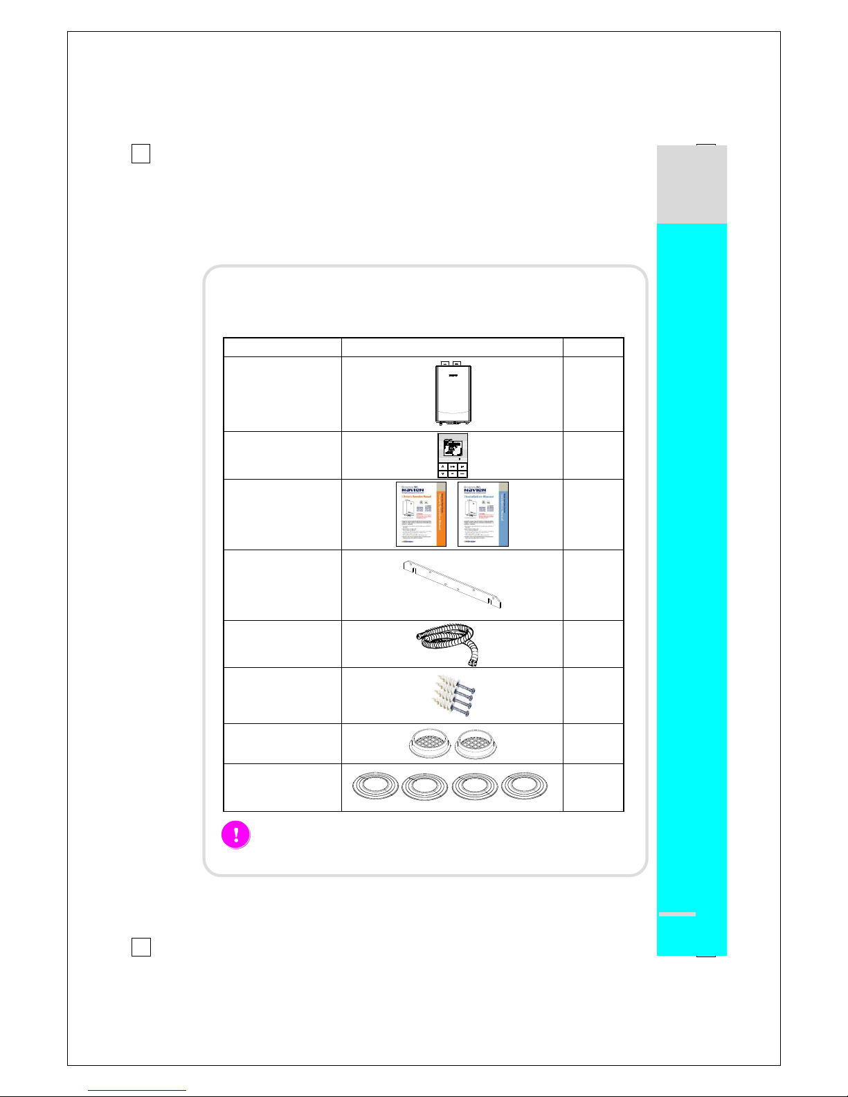
Accessories:
1. Included with the Water Heater:
Item
Description
Qty
Navien Gas
Water Heater
1
Remote Controller
1
Owner’s
Operation and
Installation
Manual
1
Wall Mounting
Bracket
1
Condensate Drain
Hose
1
Tapping Screws &
Anchors
4
Vent terminators
2
Wall Flanges
4
Check that you have received all of the above parts before installing
the Water Heater.
ACCESSORIES
Gas Water Heater Installation
4
█
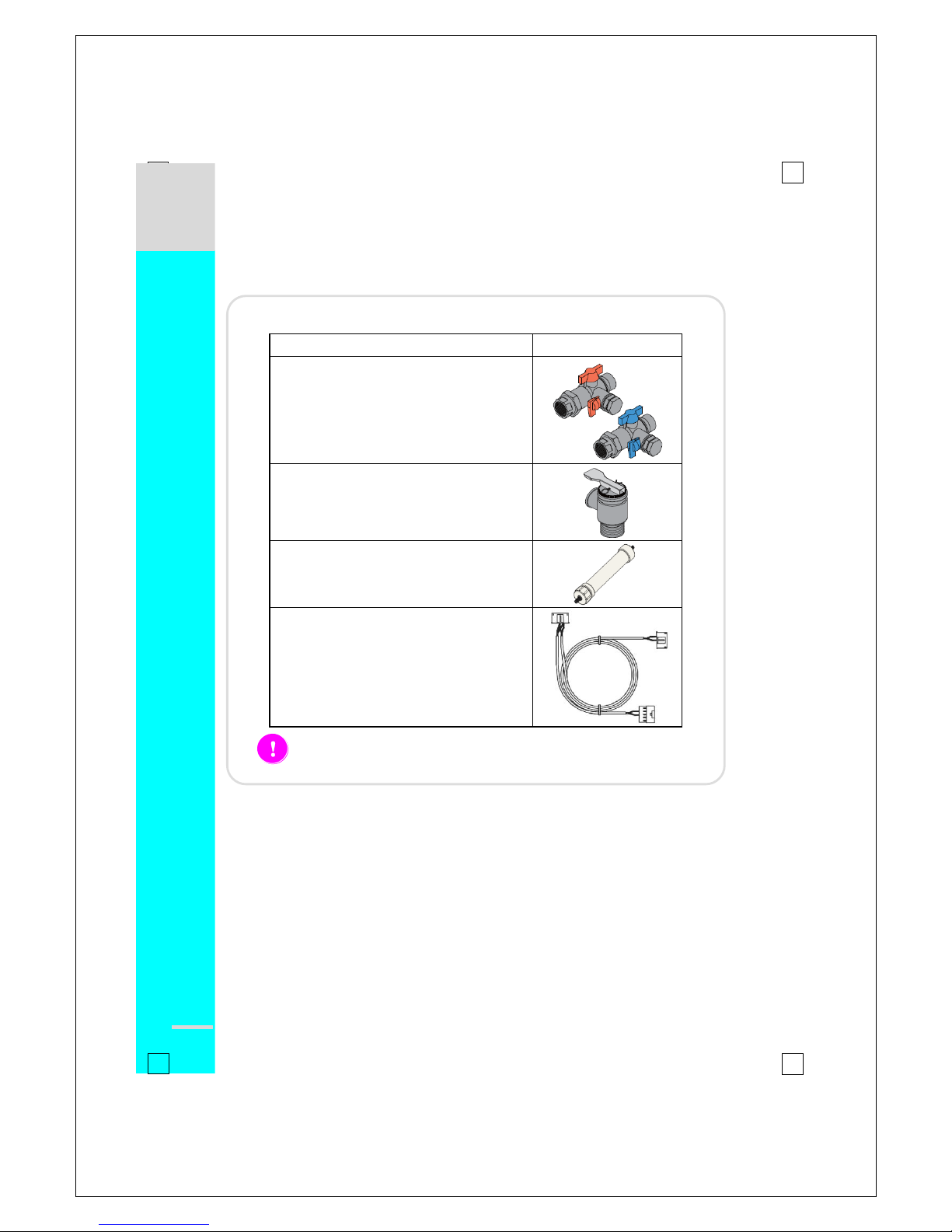
Optional Accessories:
A
2. Optional Accessories:
Item
Description
Navien Plumb Easy Valve Set
Navien Pressure Relief Valve
Navien condesate Neutralizer
Navien Ready-Link Communication Cable
Contact your Navien Water Heater supplier for optional accessories.
ACCESSORIES
Navien Gas Water Heater Installation
5
█
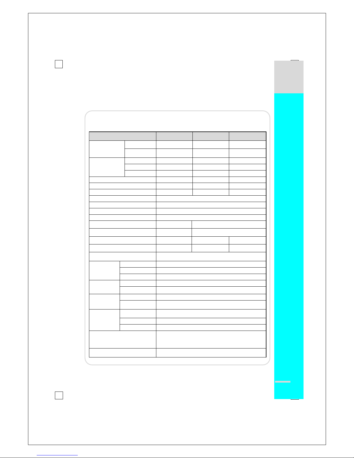
Specifications:
Please review these specifications before installation to confirm proper unit selection: As
Navien is dedicated to continuous product improvement, Navien reserves the right to
change specifications and/or design and/or discontinue any model or feature without
prior notice and without incurring obligations.
Item
NR-180(A)
NP-180(A)
NR-210(A)
NP-210(A)
NR-240(A)
NP-240(A)
Heat Capacity
(Input)
Natural Gas
Min: 15,000 Btuh
Max: 150,000 Btuh
Min: 17,000 Btuh
Max: 180,000 Btuh
Min: 17,000 Btuh
Max: 199,000 Btuh
Propane Gas
Min: 15,000 Btuh
Max: 150,000 Btuh
Min: 17,000 Btuh
Max: 180,000 Btuh
Min: 17,000 Btuh
Max: 199,000 Btuh
Heat Capacity
(Input)
35°F Rise
8.3 GPM
10.0 GPM
11 GPM
45°F Rise
6.5 GPM
7.7 GPM
8.6 GPM
77°F Rise
3.8 GPM
4.5 GPM
5.0 GPM
Dimensions
W17” x H28”x D14”
W17” x H28”x D15”
W17” x H28” xD15”
Weight NR-A, NP-A
77 lbs
86 lbs
86 lbs
Weight NR, NP
67 lbs
77 lbs
77 lbs
Installation Type
Indoor / Outdoor Wall-Hung
Venting Type
Forced Draft Direct Vent
Ignition
Electronic Ignition
Water Pressure (min-max)
15 – 150 PSI
Natural Gas Supply Pressure
(from source, Min ~ Max)
6”WC ~ 10.5” WC
5”WC ~ 10.5” WC
Propane Gas Supply Pressure
(from source, Min ~ Max)
9”WC ~ 13.5” WC
8”WC ~ 13.5” WC
Natural Gas Manifold Pressure
(min-max)
0.4”WC ~ 4.9” WC
0.4”WC ~ 3.5” WC
0.6”WC ~ 3.7” WC
Propane Gas Manifold Pressure
(min-max)
0.8”WC ~ 7.6” WC
0.8”WC ~ 5.9” WC
1.0”WC ~ 3.7” WC
Minimum Flow Rate
0 GPM for “A” models (no minimum flow rate requirement),
0.5 GPM for non-“A” models
Connection
Sizes
Cold Water Inlet
3/4” NPT
Hot Water Outlet
3/4” NPT
Gas Inlet
3/4” NPT
Power Supply
Main Supply
120VAC, 60Hz
Maximum Power
Consumption
200W (max 2A)
Materials
Casing
Cold Rolled Carbon Steel
Heat Exchangers
Primary Heat Exchanger: Stainless Steel
Secondary Heat Exchanger: Stainless Steel
Venting
Exhaust (ø3”)
ø3” PVC, ø3” CPVC, ø3” Special Gas Vent Type BH
(Class IIA (PVC) and Class I
Intake (ø3”)
PVC, CPVC, Galvanized Steel, Flex Aluminum, Flex, ABS,
Vent Clearances
0” to combustibles
Safety Devices
Flame Rod,Thermal Fuse(Overheat Cut Off device)
APS, GPS, Gas-Valve Operation Detector,
Ignition Operation Detector, Water Temperature High Limit Switch,
Exhaust Temperature High Limit Switch
Accessories
Remote Controller, Plumb Easy Valve Set,
Condensate Neutralizer, Ready-Link Communication Cable
SPECIFICATIONS
Gas Water Heater Installation
6
█
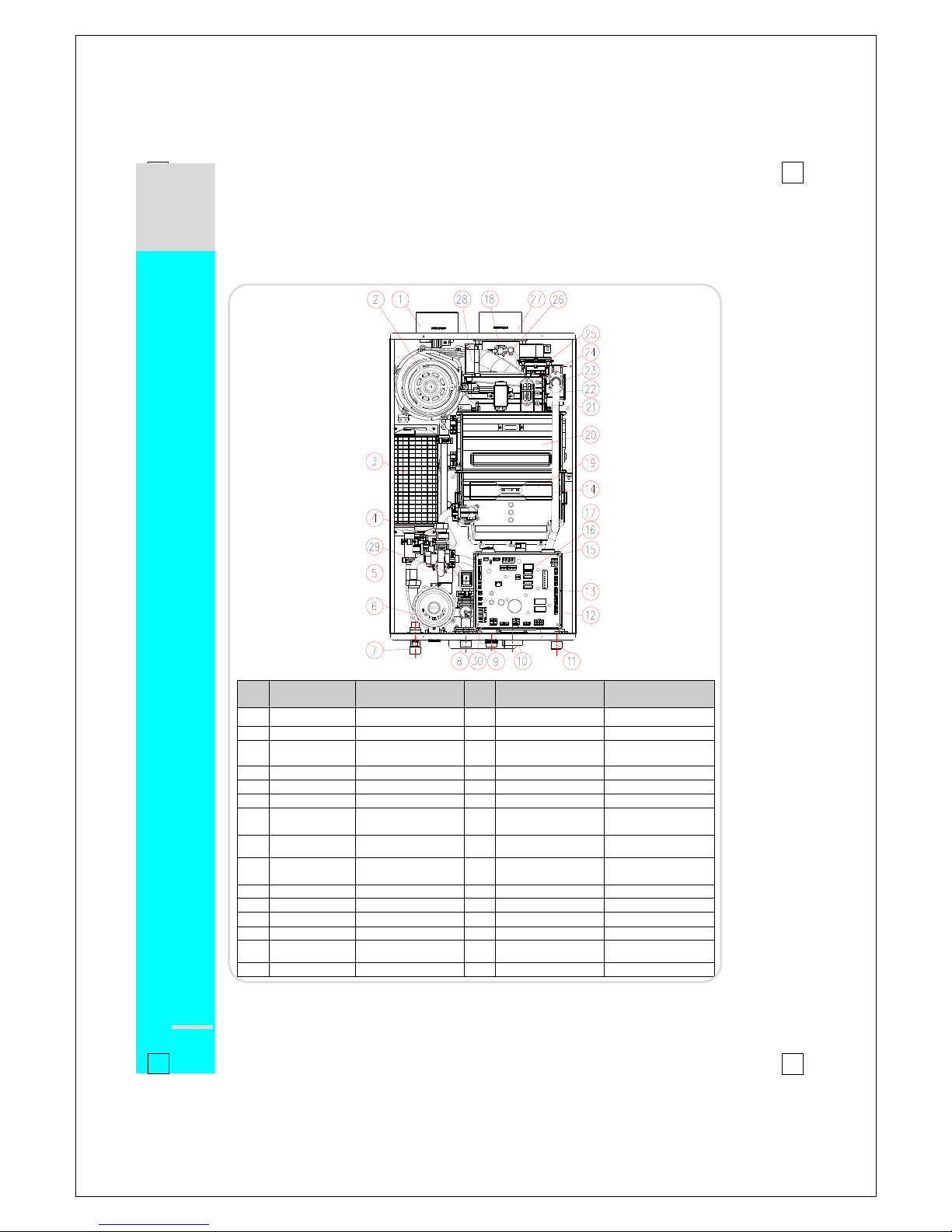
Key Components: NR-A
No
Description
Navien Part No.
No
Description
Navien Part No.
1
Intake Air Duct
BH2505400B
16
WAV
NCVM9EX00005
2
Fan Motor
NAFA9GLPCT01
17
Transformer
BH1205008A
3
Buffer Tank
PASNCWBFTANK_001
18
Exhaust Limit Switch
BH1401027A
4
Flow Sensor
BH1406004F
19
Secondary H/E
-
5
PCB Board
NACR1GS32410
20
Primary H/E
-
6
Circulation Pump
NAPU9GLPCT01
21
Ignition Transformer
BH1201041D
7
DHW Supply
Adapter
BH2507348B
22
APS Venturi
BH2501413A
8
3-Way Valve
BH2507467C
23
Manifold
PABCR180AMF_001
9
DHW Inlet
Adapter
BH2507469A
24
Burner
PABNCN30KDBN_003
10
Syphon
BH2507442C
25
APS
NASS9EX00009
11
Gas Inlet Adapter
BH2507396A
26
Exhaust Duct
BH2544004F
12
Main Gas valve
BH0901018A
27
Exhaust Pipe
BH2505401B
13
GPS Venturi
BH2507359B
28
Air Intake Guide
BH2543002C
14
Gas Pipe
BH2507509A
29
Power Switch
BH1426002A
15
GPS
NASS9EXGPS01
30
Water Leakage Detector
-
COMPONENTS & DIMENSIONS
O
U
T
I
N
Navien Gas Water Heater Installation
7
█
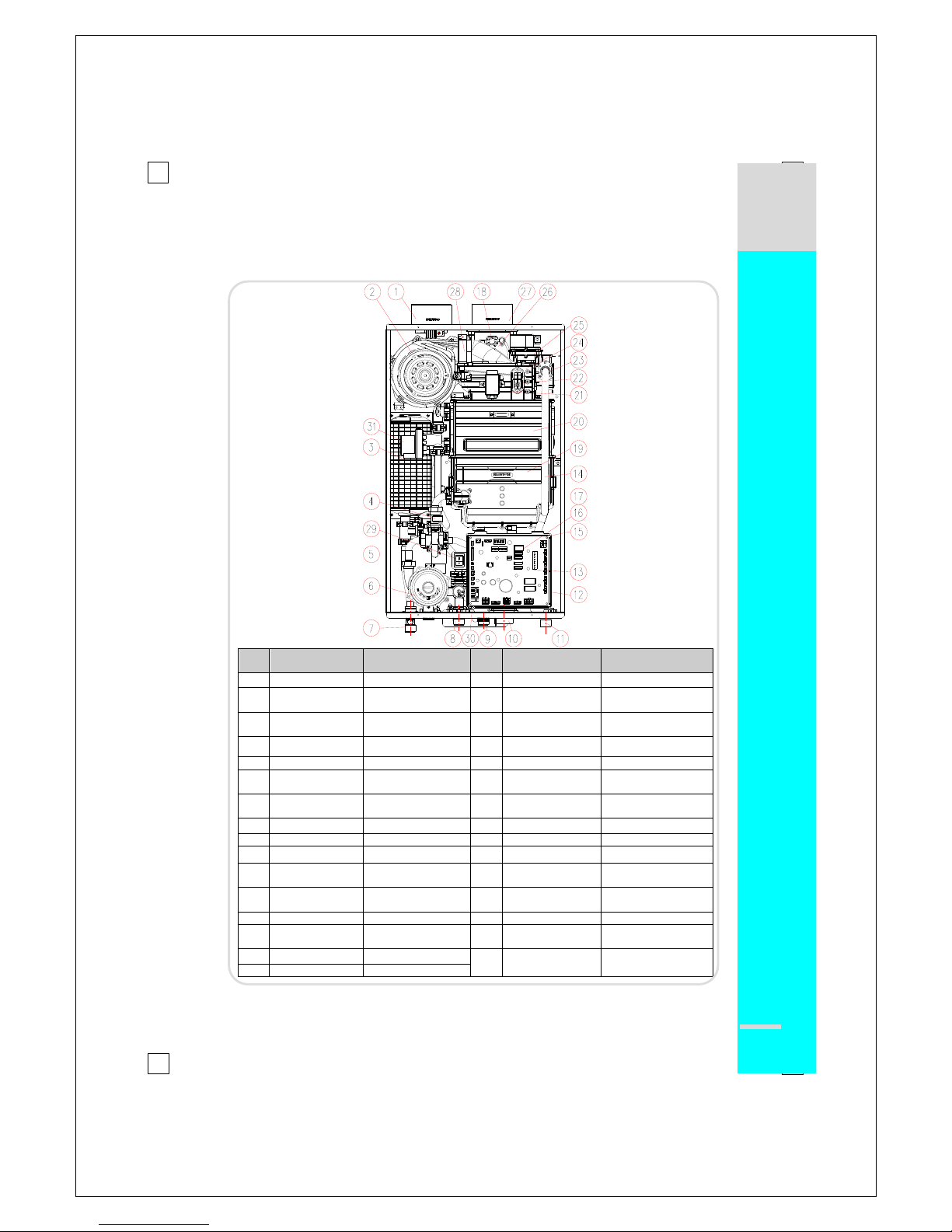
Key Components: NP-A
No
Description
Navien Part No.
No
Description
Navien Part No.
1
Intake Air Duct
BH2505400B
17
Transformer
BH1205008A
2
Fan Motor
NAFA9GLPCT01
18
Exhaust Limit Switch
BH1401027A
3
Buffer Tank
PASNCWBFTANK_001
19
Secondary H/E
-
4
Flow Sensor
BH1406004F
20
Primary H/E
-
5
PCB Board
NACR1GS32410
21
Ignition Trans
BH1201041D
6
Circulation Pump
NAPU9GLPCT01
22
APS Venturi
BH2501413A
7
DHW Supply
Adapter
BH2507348B
23
Manifold
PABCR180AMF_001
8
3-Way Valve
BH2507467C
24
Burner
PABNCN30KDBN_003
9
DHW Inlet Adapter
BH2507469A
25
APS
NASS9EX00009
10
Syphon
BH2507442C
26
Exhaust Duct
BH2544004F
11
Gas Inlet Adapter
BH2507396A
27
Exhaust Pipe
BH2505401B
12
Main Gas valve
BH0901018A
28
Air Intake Guide
BH2543002C
13
GPS Venturi
BH2507359B
29
Power Switch
BH1426002A
14
Gas Pipe
BH2507351A
30
Water Leakage
Detector
-
15
GPS
NASS9EXGPS01
31
WAV
NCVM9EX00005
16
2-Way Valve
BH0914002B
COMPONENTS & DIMENSIONS
O
U
T
I
N
Gas Water Heater Installation
8
█
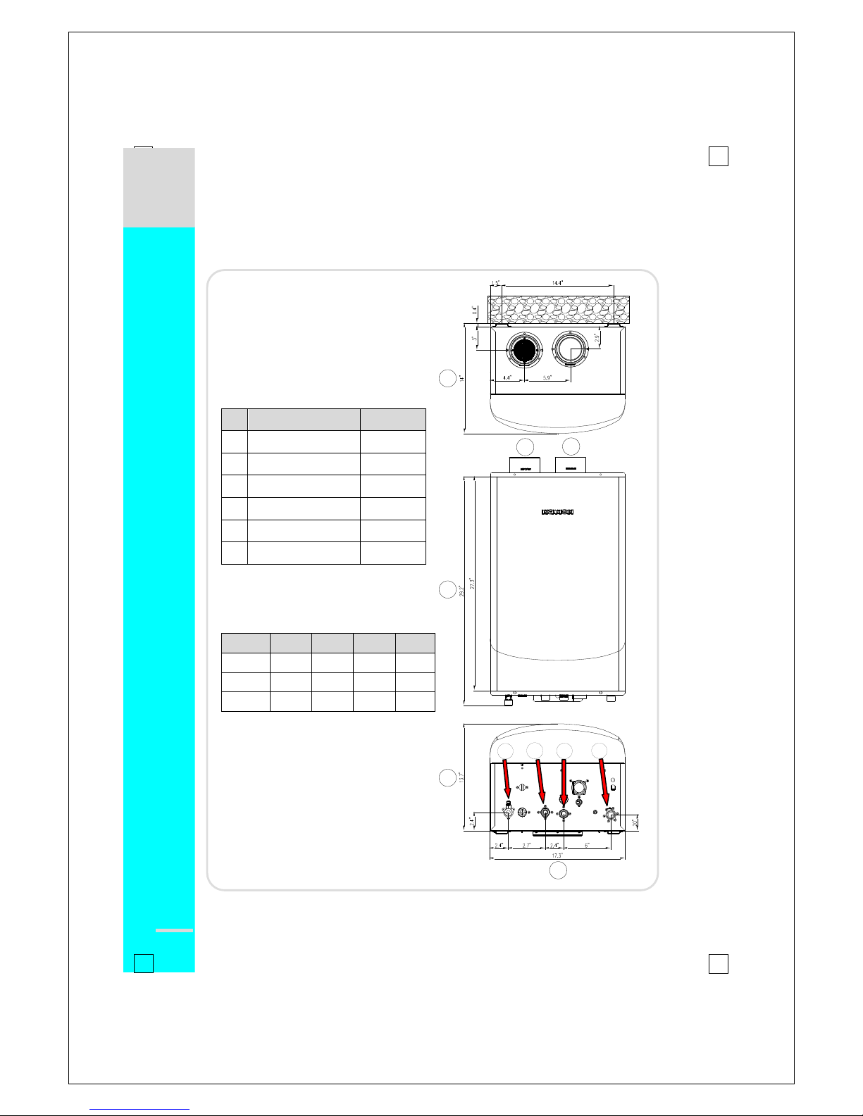
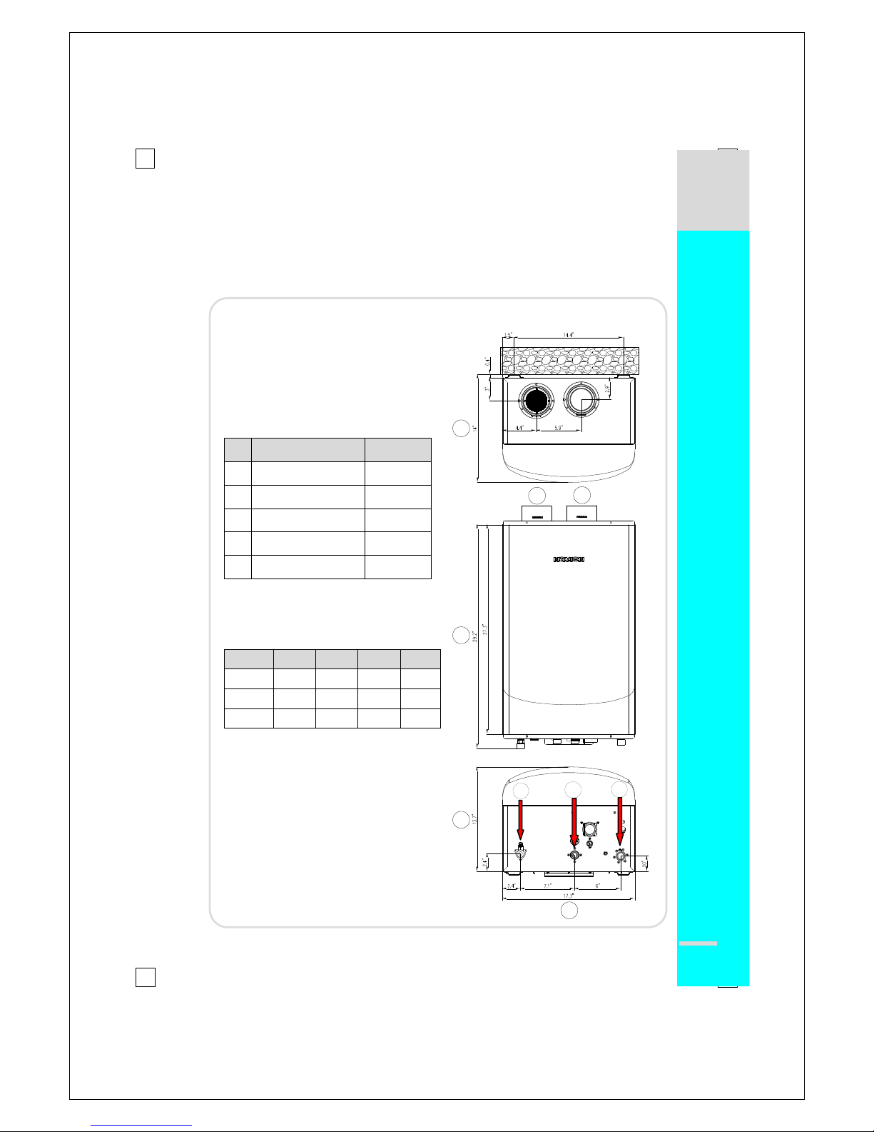
Dimensions: NR-A, NP-A
NR-A , NP-A
Description
Diameter A Exhaust
3” B Air Intake
3”
C
DHW Supply
¾”
D
Recirculation Inlet
¾”
E
Cold Water Inlet
¾” F Gas Inlet
¾”
NR-A , NP-A Type Dimensions
Model
① ② ③ ④ 180
14”
29.2”
13.7”
17.3”
210
15.2”
29.2”
14.9”
17.3”
240
15.2”
29.2”
14.9”
17.3”
COMPONENTS & DIMENSIONS
A
B
1
2
3
4
C
D
E
F

Navien Gas Water Heater Installation
9
█
Key Components: NR
No
Description
Navien Part No.
No
Description
Navien Part No.
1
Intake Duct
BH2505400B
17
Transformer
BH1205008A
2
Fan Motor
NAFA9GLPCT01
18
Exhaust Limit Switch
BH1401027A
3
Flow Sensor
BH1406004F
19
Secondary H/E
-
4
Power Switch
BH1426003A
20
Primary H/E
-
5
PCB Board
NACR1GS32401
21
Ignition Trans
BH1201041D
6
Heater
BH1501047B
22
APS Venturi
BH2501413A
7
Heater Clip
BH2507447A
23
Manifold
PABCR180AMF_001
8
DHW Supply Adapter
BH2507348B
24
Burner
PABNCN30KDBN_003
9
DHW Inlet Adapter
BH2507469A
25
APS
NASS9EX00009
10
Syphon
BH2507452C
26
Exhaust Duct
BH2544004F
11
Gas Inlet Adapter
BH2507396A
27
Exhaust Pipe
BH2505401B
12
Main Gas valve
BH0901018A
28
Air Intake Guide
BH2543002C
13
GPS Venturi
BH2507359B
29
Bypass Mixing Valve
AAVC9EXMIX01
14
Gas Pipe
BH2507351A
30
Freeze Protect Switch
BH1402001A
15
GPS
NASS9EXGPS01
31
Mixing Trans
BH1205013A
16
WAV
NCVM9EX00005
COMPONENTS & DIMENSIONS
Gas Water Heater Installation
10
█
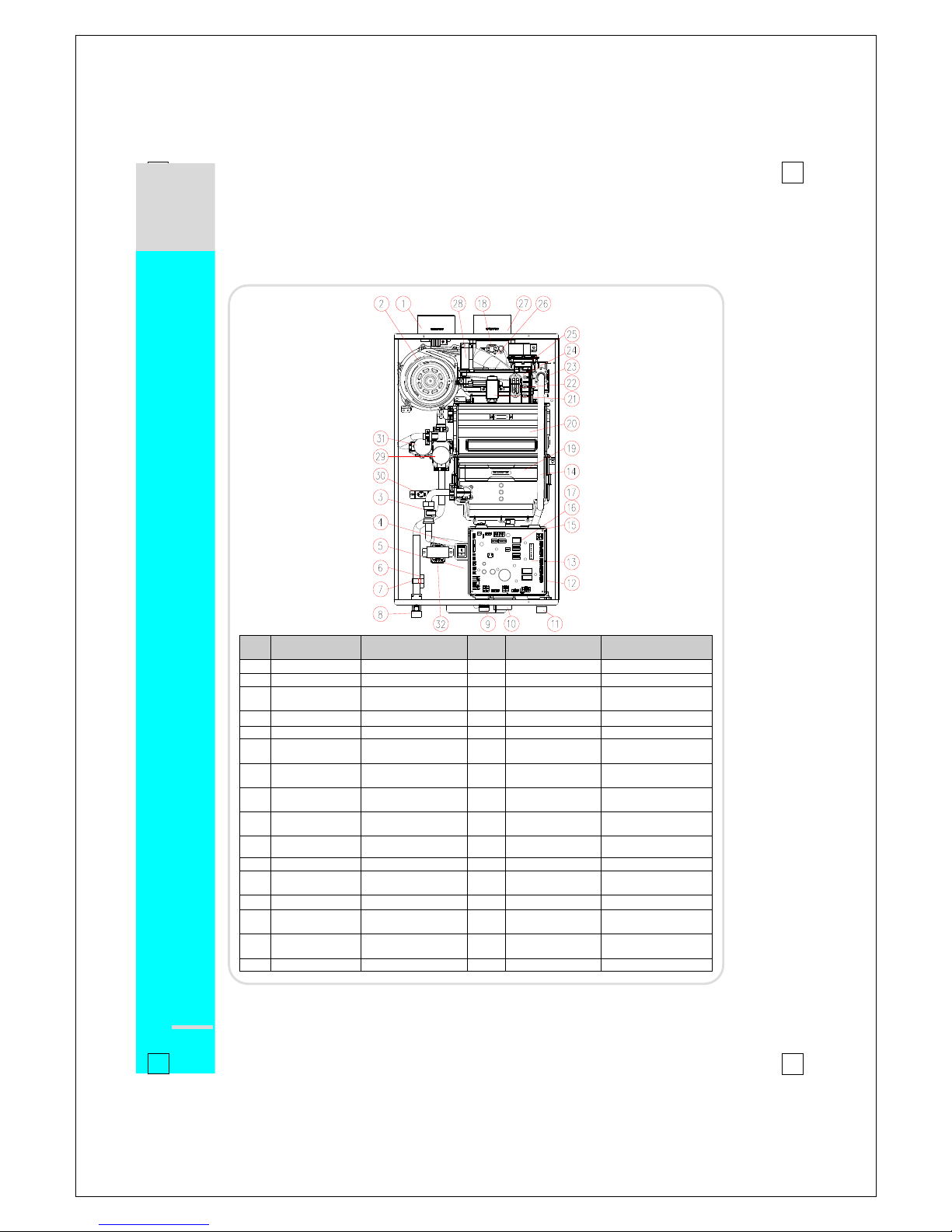
Key Components: NP
No
Description
Navien Part No.
No
Description
Navien Part No.
1
Intake Air Duct
BH2505400B
17
Transformer
BH1205008A
2
Fan Motor
NAFA9GLPCT01
18
Exhaust Limit Switch
BH1401027A
3
Flow Sensor
BH1406004F
19
Secondary H/E
-
4
Power Switch
BH1426003A
20
Primary H/E
-
5
PCB Board
NACR1GS32401
21
Ignition Trans
Bh1201041D
6
Heater
BH1501047B
22
APS Venturi
BH2501413A
7
Heater Clip
BH2507447A
23
Manifold
PABCR180AMF_001
8
DHW Supply
Adapter
BH2507348B
24
Burner
PABNCN30KDBN_003
9
DHW Inlet Adapter
BH2507469A
25
APS
NASS9EX00009
10
Syphon
BH2507452C
26
Exhaust Duct
BH2544004F
11
Gas Inlet Adapter
BH2507396A
27
Exhaust Pipe
BH2505401B
12
Main Gas valve
BH0901018A
28
Air Intake Guide
BH2543002C
13
GPS Venturi
BH2507359B
29
WAV
NCVM9EX00005
14
Gas Pipe
BH2507351A
30
Freeze Protect
Switch
BH1402001A
15
GPS
NASS9EXGPS01
31
Bypass Mixing Valve
AAVC9EXMIX01
16
2-Way Valve
BH0914002B
32
Mixing Trans
BH1205013A
Navien Gas Water Heater Installation
11
█
Dimensions: NR, NP
NR, NP
Description
Diameter
A
Exhaust
3”
B
Air Intake
3”
C
DHW Supply
¾”
D
Cold Water Inlet
¾”
E
Gas Inlet
¾”
NR, NP Type Dimensions
Model
① ② ③
④
180
14”
29.2”
13.7”
17.3”
210
15.2”
29.2”
14.9”
17.3”
240
15.2”
29.2”
14.9”
17.3”
COMPONENTS & DIMENSIONS
A
B
1
2
3
4
C
D
E
Gas Water Heater Installation
12
█
Installation Warnings:
Read all safety warnings in the “Owner’s Operation Manual”. The additional safety
issues outlined below must also be followed completely when installing this Navien
Water Heater:
1. This unit is designed for indoor installations. DO NOT operate this unit without the vent piping
connected. Exhaust gases must be completely expelled out of the building.
2. DO NOT use this appliance if any part has been underwater. Immediately call a qualified
service technician to inspect the appliance and replace any part of the control system and any
gas control which has been underwater.
3. Be sure not to reverse the water and gas connections as this may damage the gas valves.
4. Water temperature over 125°F can cause severe burns instantly or death from scalds. If the
proposed water heater outlet temperature is above 125°F, a thermostatically controlled mixing
valve (or a temperature limiting valve) for reducing point of use water temperature is
recommended to reduce the risk of scald injury. Contact a licensed plumber or the local
plumbing authority for further information.
5. The appliance should be located in an area where leakage within the unit or at its connections
will not result in damage to the surrounding area. Navien will not be responsible for any
damage resulting from leaking if adequate drainage is not provided.
6. DO NOT use this water heater for any purpose other than water heating and space heating.
7. If the water quality is known to have high acidity and/or high hardness, water treatment is
recommended to maintain full warranty. Consult the local water authority.
8. Protect against snow accumulation around the vent terminations. Ensure the exhaust vent
pipe and the intake airpipe remain clear from obstructions at all times.
9. DO NOT overtighten fittings as pipe and/or fitting damage may occur causing leakage.
10. DO NOT install water heater where subject to vibtations.
11. The vent for this appliance shall not terminate over public walkways, near soffit vents, crawl
space vents, or other areas where condensate or vapor could create a nuisance, hazard, or
cause property damage. The vent also should not terminate where condensate or vapor could
cause damage or could be detrimental to the operation of regulators, relief valves, or other
equipment.
12. For other than a direct vent appliance, the appliance must be located as close as possible to a
chimney or gas vent.
13. Should overheating occur or if the gas supply fails to shut off, turn off the manual gas control
valve to the appliance.
Follow all local codes and/or the most recent edition of the National Fuel Gas
Code (ANSI Z223.1/NFPA 54) in the USA or the Natural Gas and Propane
Installation Code in Canada (CAN/CGA B149.1).
Navien Gas Water Heater Installation
13
█
Getting Started:
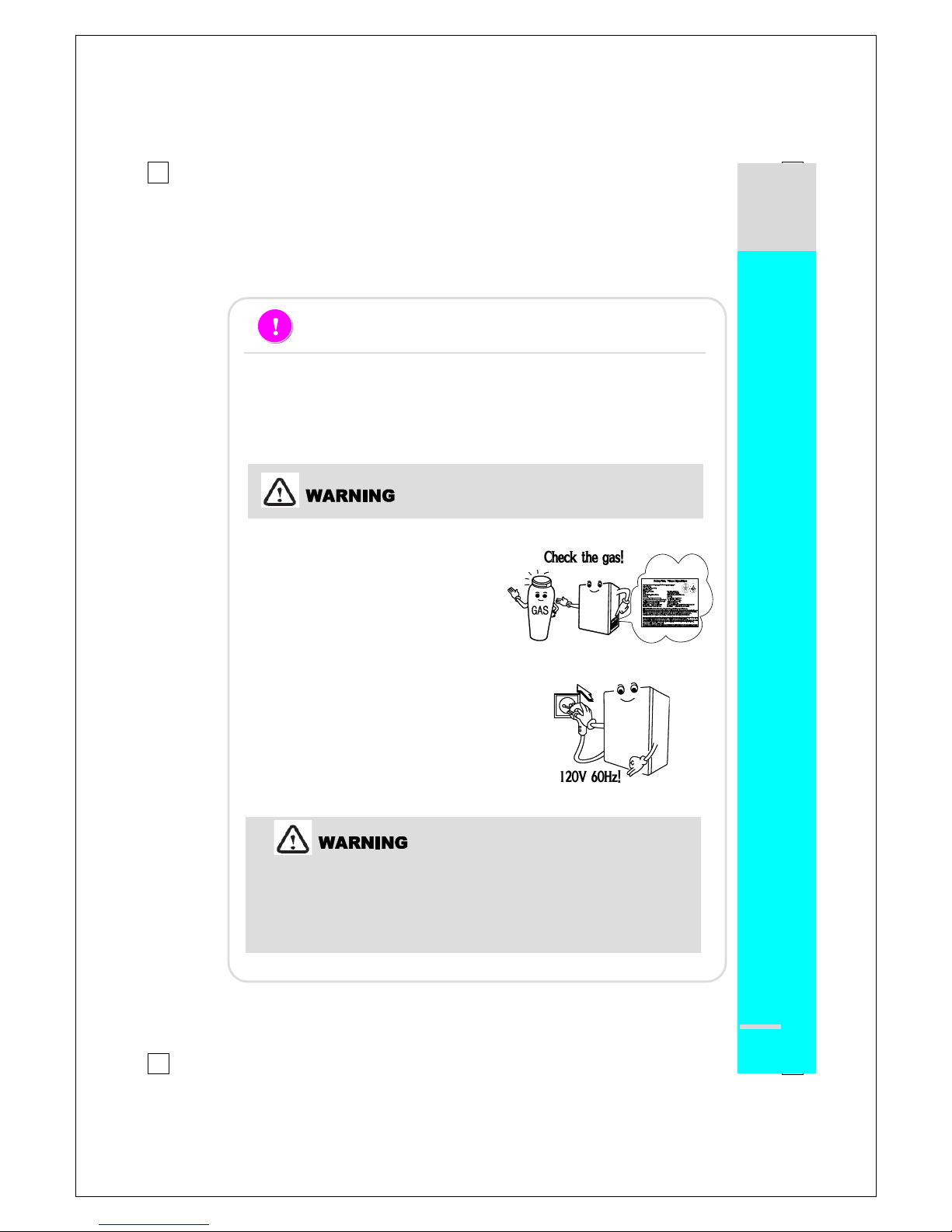
CHECK THE RATING PLATE
Navien units come from the factory configured for use with either Liquid Propane (LP) or
Natural Gas (NG). Before starting the installation, check the rating plate located on
the backside of the front cover of the Water Heater to ensure the unit matches gas type,
gas pressure, water pressure and electrical supply. If the unit does not match
following requirements, do not install.
Be sure the gas type and electricity voltage
match the Rating Plate.
Use only the same gas type indicated on
the rating plate of the Navien Water Heater.
Using different gas type will cause
abnormal combustion and Water Heater
malfunction.
Be sure to use 120V AC, 60Hz, minimum
2A current. Using abnormally high or low
AC voltage may cause abnormal operation,
and may reduce the life expectancy of this
product.
If not certain, please contact Navien immediately.
Conversion of this unit from natural gas to propane or vise versa cannot be done in
the field. Please re-confirm gas type on the rating plate (left side of unit) before
installing. DO NOT attempt any field conversion; this will result in dangerous
operating conditions and will void all warranty.
Navien America Inc. is not liable for any property damage and/or personal
injury resulting from unauthorized conversions.
Gas Water Heater Installation
14
█
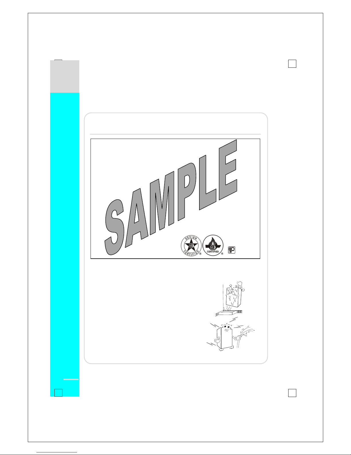
Check Rating Plate:
Sample Rating Plate
DO NOT install the Navien Water Heater in areas with excessively high humidity:
DO NOT install the unit in a location where
there is excessively high humidity such as
bathrooms, damp crawl space and other areas
such as this. This may cause the unit to
malfunction.
To avoid possible electrical shock, DO NOT
touch the internal components of the water
heater or the power cord with wet hands.
DO NOT splash excessive water on the Water
Heater or remote controller when cleaning: they
are water resistant, not water proof.
Rating Plate, *Plaque Signalétique
Automatic Instantaneous Water Heater,
*Chauffe-eau automatique instantané
Navien America Inc.
1371 Santa Fe Drive, Tustin, CA 92780
Tel: (714) 258 - 9005
Model No
. , *N de modèle
Type of Gas
, *Type de gaz
NR-180 NG *GAZ NATUREL
Max. Input Rating,
*Entrée GPL max.
Min. Input Rating,
*Débit calorifique max.
150,000 Btuh 15,000 Btuh
Recovery Rating,
*Calibre de recouvrement :
227 Gallons/Hour
, *gallons/heures
Max. Inlet Gas Pressure,
*Pression max. de gaz d’entrée
10.5 Inches W.C.
*pouces W.C.
Min. Inlet Gas Pressure, *Pression min. de gaz d’entrée
6.0 Inches W.C.
,*pouces W.C.
Manifold Pressure, *Pression d’admission
4.9 Inches W.C.
*po W.C.
Electrical Rating, *Régime nominal électrique
AC
*c.a.
120 Volts 60Hz Use less than 2 Amp,
*Utilise moins de 2A
Max. Water Pressure,
*Pression d’eau max.
150 Psi
*lb/po2
ANSI Z21. 10. 3b – CSA 4.3B-2004
RATING PLATE
Navien Gas Water Heater Installation
15
█
Locating the Water Heater:
Location selection may not necessarily affect the operation of the
Navien water heater but it will affect the customer’s experience and level
of satisfaction with the product. Understanding that each building is
different, the contractor will have to select the best location based on a
combination of the following factors:
1. Locate Navien Water Heater close to a drain where condensed water and possible
water leakage will not damage to surrounding areas. A significant amount of
condensed water will be produced each time the water heater is used. In addition,
as with any water heating appliance, the potential for leakage at some time in the
life of the product does exist. If there is no drain, Navien will not be responsible for
any water damage that may occur.
2. Locate where the domestic water supply comes into the building.
3. Locate where the gas supply comes into the building.
4. Locate the unit close to the main fixtures in the home (bathrooms, kitchen, laundry,
etc.). Select a location that minimizes the water piping distance between the major
fixtures. If the distances are long or an appliance needs “instant” hot water, Navien
recommends using its “A” models and running a recirculation line back from the
furthest fixture. Insulate as much of the hot water supply line and recirculation line
as possible.
5. Consider Venting Options: Select a location that minimizes the amount of venting
required. Consider venting restrictions from windows, doors, air intakes, gas meters,
neighbor’s houses, etc.
Maintain proper clearances from any openings in the building (see chart in
venting section).
Navien Water Heater requires a minimum clearance of 12 inches above the
exterior grade.
Do not install the water heater where moisture from the exhaust may cause
discoloration or damage to walls.
Install the exhaust vent so that there are no obstacles around the termination and
so that exhaust cannot accumulate.
Do not enclose the termination.
Do not install the water heater near vents for heating or cooling. A minimum of 4
feet (1.2m) should be maintained.
6. It is not recommended to install the Water Heater in bathrooms, bedrooms, any
occupied rooms normally kept closed, or in indoor areas without proper venting.
LOCATION SELECTION
Gas Water Heater Installation
16
█
Locating the Water Heater:
7. Select a location that ensures the unit will have sufficient and clean combustion air;
avoid installation where dust or debris will accumulate; avoid installation where
chemical agents (e.g., hair spray, spray detergent, chlorine, chemicals) are used.
8. If installing into a very tight space or corner, please ensure there is sufficient service
and maintenance access to all gas and water piping to ensure that regular
maintenance (such as cleaning the water filter, the air filter and the condensate trap)
will not become problematic.
Allow sufficient clearance:
Indoor Install
Outdoor Install
Top of Water Heater
Min. 9 inches
Min. 36 inches
Back of Water Heater
Min. 0.5 inches
Min. 0.5 inches
Front of Water Heater
Min 4 inches
Min. 24 inches
Sides of Water Heater
Min. 3 inches
Min. 3 inches
Bottom of Water Heater
Min. 12 inches
Min. 12 inches
9. DO NOT install in an area that contains or stores gasoline or other flammables.
10. Ensure that combustibles are clear of the immediate area. Ensure hanging laundry
or other such items will not impede the air movement into or out of the Water Heater
or its venting.
11. For commercial applications, avoid greasy fumes or a large amount of steam; take
measures to prevent the fumes and steam from entering in the equipment.
█
Mounting the Unit to the Wall:
1. All Navien units come with an upper mounting bracket pre-drilled at 16” on
center for easy installation on standard stud walls. Affix the bracket to the wall
securely, ensuring that it is level and that is can support the weight of the Water
Heater. If the strength of the wall is not sufficient, reinforce the area to prevent
any unsafe situations.
2. If the framing is not standard, reinforment of the wall is required or if installing
on an uneven surface, fasten ¾” plywood to the stud wall and then attach the
mounting brackets to the plywood.
3. When using the supplied mounting bracket, it creates a 5/8” clearance from the
back of the unit.
4. The upper bracket is installed on the wall and the Water Heater is then hung on
the bracket. On the back of the Water Heater at each of the top corners, there is
a hanger bracket on the back of the Water Heater that interlocks with a tab on the
wall mounting bracket.
▒
S
E
L
E
C
T
I
N
G
A
L
O
C
A
T
I
O
N
LOCATION SELECTION
Navien Gas Water Heater Installation
17
CAUTION
This Water Heater must only be used with the following water supply system conditions :
With clean, potable water free of corrosive chemicals, sand, dirt, of other contamintes.
With inlet water temperature above 32℉ (0℃), but not exceeding 140℉ (60℃).
Free of lime and scale deposits.
█
Plumbing:
Pipe Sizing
The water fittings on the Navien Water Heater are ¾”.
Although Navien’s water connections are ¾”, if the installation site has only ½” plumbing
throughout the building, it is NOT necessary to upsize the water lines to ¾” when installing a
single unit.
When installing multiple units to supply high volumes of hot water either in residential (multi-
head shower systems for example) applications or in commercial applications, the number of
Navien Water Heaters required and the header pipe sizing needs to be properly sized to meet
the total hot water demand. A water pressure of 40 PSI is recommended for each Water Heater
for proper operation of the Water Heaters. Consult the Navien website or call for further
information on sizing such applications.
Water Piping Guidelines
All pipes, pipe fittings, valves and other components, including solder, must be approved
for use in potable water systems.
The use of unions and manual shut off valves on both the cold water inlet and DHW outlet
are recommended.
The longer the piping, the longer it takes to get hot water to the fixtures. Make the hot
water piping system as short as possible.
To conserve water and energy, insulate all water piping especially the hot and recirculation
water lines. DO NOT cover the drain or pressure relief valve.
After the Water Heater has been installed, be sure to clean the inlet water filter located
within the cold inlet and then test the unit. The inlet water filter is there to prevent debris
from entering your heater. This will need to be cleaned periodically to maintain optimum
flow; See “draining the unit” and “cleaning the inlet water filter” procedures in the
maintenance section of the operation manual for instructions on these two procedures.
Space Heating
Piping and components connected to the Water Heater for the space heating application
shall be suitable for use with potable water.
The effect that toxic chemicals, such as used for boiler treatment, shall not be introduced
into the potable water used for space heating.
The effect that a water heater which will be used to supply potable wter shall not be
connected to any heating system or component(s) previously used with a nonpotable
water heating appliance.
Instructions that when the system requires water for space heating at temperatures higher
than required for other uses, a means such as a mixing valve shall be installed to temper
the water for those uses in order to reduce scald hazard potential. These instructions shall
include a piping diagram(s) for a typical installation.
PLUMBING
Gas Water Heater Installation
18
█
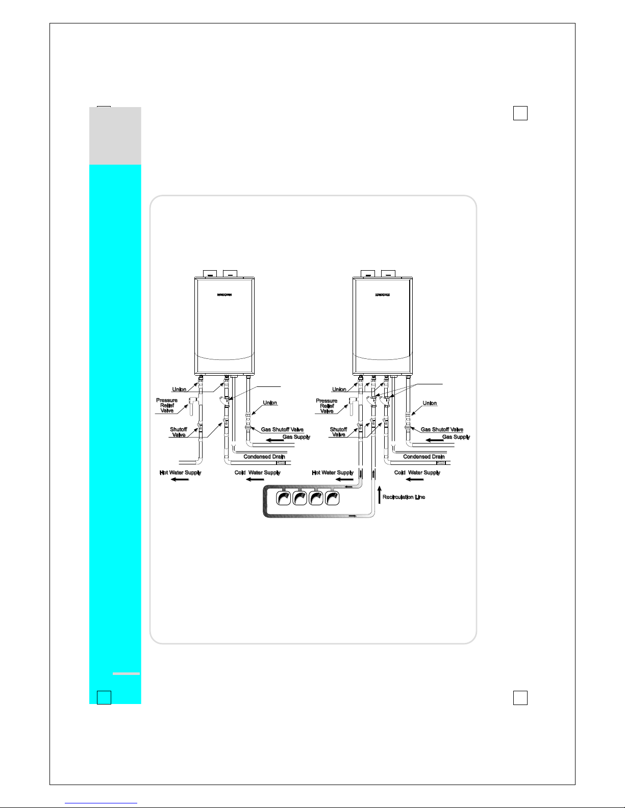
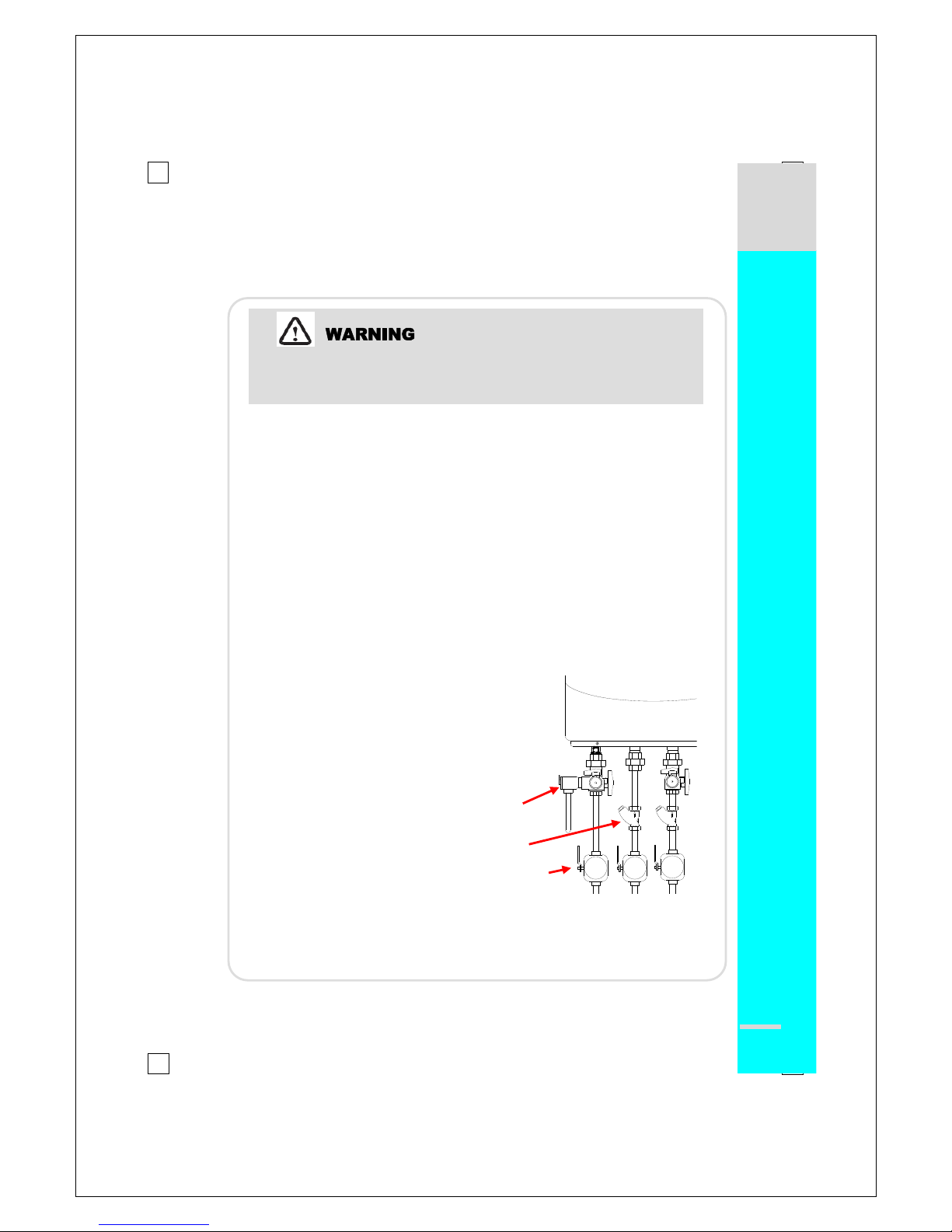
Plumbing:
Water Piping Guidelines
NR, NP Series NR-A, NP-A Series
NOTICE : If using mixing valves on the outlet, choose one which prevents cold water
pressure from overcoming hot water line pressure.
The flow rate of hot water may vary when more than two faucets(appliances,
fixtures, etc.) are being used simultaneously.
If a Water Heater is installed in a closed water supply system, such as one
having a backflow preventer in the cold water supply line, means shall be
provided to control thermal expansion. Contact the water supplier or local
plumbing inspector on how to control this situation.
PLUMBING
Y-Strainer
Y-Strainer
Navien Gas Water Heater Installation
19
█
Pressure Relief Valve:
An approved ¾”, maximum 150 PSI pressure relief valve must be installed on the
hot water outlet, as close to the unit as possible. Please see below for more
information on approved pressure relief valves.
Each Navien Water Heater has a high-temperature shut off switch built in as a
standard safety feature (called a temperature high limit switch) therefore a “pressure
only” relief valve is required. This unit does not come with a pressure relief valve
but one must be installed on the hot water outlet.
The discharge capacity of the pressure relief valve must be at least equal to the
maximum pressure rating of the Water Heater.
The maximum input BTUH rating on the valve must be equal to or greater than the
maximum input BTUH rating of the Water Heater.
The discharge piping for the pressure relief valve must be directed so that the hot
water cannot splash on anyone or on nearby equipment. Attach the discharge tube
to the pressure relief valve and run the end of the tube to within 6" from the floor.
This discharge tube must allow free and complete drainage without any restrictions.
No reducing coupling or other restriction may be installed in the discharge line.
The following ¾”, maximum 150 PSI valves are
examples of valves approved for use with all
Navien products:
1. Wilkins P-1000A (Zurn Industries)
2. Conbraco 17-402-04
3. Watts Industries 3L(M7)
4. Cash Acme FWL-2 ¾”
Instructions for pressure, temperature and vacuum relief valves shall specify that no
valve is to be placed between the relief valve and the tank. The instructions shall specify
installation in such a manner that the discharge from temperature and pressure relief
valves will be conducted to a suitable place for disposal when relief occurs and that no
reducing coupling or other restriction be installed in the discharge line.
PRESSURE RELIEF VALVE
Failure to comply with the guidelines on installing the pressure relief valve
and discharge piping can result in personal injury, death or substantial
property damage.
Pressure
Relief Valve
Hot Rec Cold
Y-Strainer
Shut-off Valve
Gas Water Heater Installation
20
█
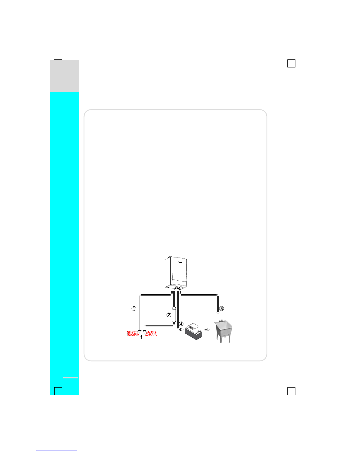
Disposal of Condensate:
▶ This Navien Water Heater is a high efficiency gas appliance that creates
condensation when it operates. Condensation has an acidic (pH) of approximately
3~4. Follow your local code with regards to the disposal of condensation. Here are
several options for the Disposal of Condensate (see diagram below):
① From Water Heater direct to drain.
② From Water Heater to neutralizer to drain.
③ From Water Heater to laundry tub (bottom of water heater must be above the
height of laundry tub; must have a negative slope to properly drain).
④ From Water Heater to condensate pump to laundry tub (for long distances
between water heater and laundry tub or when bottom of Water Heater is
installed below height level of laundry tub).
▶ All Navien’s NR & NP Series Water Heaters are condensing gas appliances. A
condensate trap comes factory installed inside each Water Heater.
▶ All condensate must be drained in accordance with all local regulations. Navien
recommends draining the condensate to a laundry tub as the alkalie in the
detergent from the washing machine will neutralize the acid in the condensation. If a
laundry tub is not close by, you may need to install a condensate pump to push the
condensate to the nearest laundry tub or consider installing a condensate
neutralizer so that you can release the neutralized (non-acidic) water into a regular,
nearby drain.
▶ If a neutralizer is installed, periodic replacement of the lime stone (or neutralizing
agent) will be required. The rate of depletion of the lime stone varies upon usage of
the water heater. During the first year of operation, please check the neutralizer
every few months for depletion. If you notice any depletion, order some
replacement neutralizer lime stone.
▶ Use only corrosion-resistant materials for the condensate drain lines such as ¾” ID
PVC pipe vinyl or plastic hose.
CONDENSATE DISPOSAL
Floor drain
Navien Gas Water Heater Installation
21
█
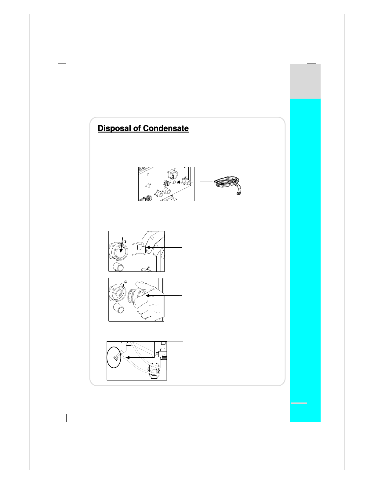
Condensate Drain & Cleaning:
A condensate drain tube is included with the Navien Water Heater. This tube
must be connected to the port at the bottom of the unit (see below). The end of
the tube should drain to a laundry tub or to a floor drain. If additional tubing is
required, any ¾” polyvinyl tubing should suffice.
Over time, blockage of the siphon by debris may occur; when the condensate
cannot be released, the water heater will go into error and will shut down. When
this occurs, the siphon must be cleaned. To clean, you will need a bucket to
collect any residual water. See figures below.
Remove retaining clip
Prepare bucket; twist and remove cap;
drain, clean out siphon and re-insert cap
and retaining clip.
Once the cap and clip have been re-inserted, the syphon must be re-filled. See
figure below.
Open the valve and water will begin to fill in
the syphon. Fill the siphon to the top and
then close the valve.
Open a hot water faucet; examine the
open end of the condensate drain line to
ensure no flue gases are exiting from that
pipe. If the flue gases are exiting,
immediately stop the unit and call Navien
for additional instructions.
CONDENSATE DISPOSAL
siphon
Gas Water Heater Installation
22
█
Gas Piping:
Navien recommends the Water Heater be the first appliance installed
downstream of the gas meter to ensure it will have sufficient gas supply.
Use the charts on the following pages to properly size the gas supply line.
The gas connection fitting on all Navien units is ¾”. DO NOT use less than ¾” piping.
When using flexible gas line, ensure the pipe’s inner diameter is sufficient to supply
the required BTUs, also ensure that the flexible line has no crimps or tight bends this
will restrict gas flow.
Install a manual gas shut-off valve on the gas supply line and the water heater.
When using rigid pipe, Navien recommends the installation of a union on the gas
supply pipe close to the water heater to facilitate any future maintenance and
service.
1. The minimum and maximum inlet gas pressures are:
Natural Gas Min. 5.0(6.0 : 180)” WC - Max. 10.5” WC
Propane Gas Min. 8.0(9.0 : 180)” WC - Max. 13.5” WC
2. Gas pressures over and above the specified ranges will result in adverse
performance and dangerous operating conditions, any damage resulting from
extreme gas supply pressures will not be covered by the limited warranty.
3. Until pressure testing of the main gas supply line is completed, ensure the gas line to
the Navien Water Heater is disconnected to avoid any damage to the Water Heater.
4. The appliance must be isolated from the gas supply piping system by closing its
individual manual shutoff valve during any pressure testing of the gas supply piping
system at test pressures equal to or less than ½ psi (3.5 kPa);
5. The gas appliance and its gas connections must be leak tested before placing the
appliance in operation. Leaks can be found by using a gas leak detetion device or
by applying soapy water to all gas fittings. Should bubbles occur tighten those
connections and re-test.
6. Always purge the gas line for any debris before connecting to the Water Heater gas
inlet.
7. Never use an open flame to test for gas leaks, as property damage, personal injury,
or death could result.
GAS PIPING
Gas supply Line Pressures:
Navien Gas Water Heater Installation
23
█
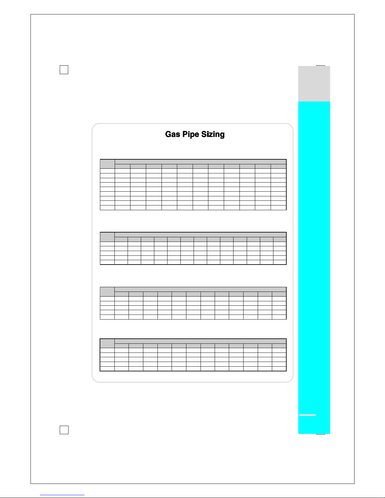
Gas Pipe Sizing Chart:
Maximum Natural Gas Delivery Capacity
in Cubic Feet (
ft3) per Hour (0.60 Specific Gravity, 0.5" WC Pressure Drop)
Pipe
Size
Length in Feet
10'
20'
30'
40'
50'
60'
70'
80'
90'
100'
125'
3/4"
363
249
200
171
152
138
127
118
111
104
93
1"
684
470
377
323
286
259
239
222
208
197
174
1 1/4"
1,404
965
775
663
588
532
490
456
428
404
358
1 1/2"
2,103
1,445
1,161
993
880
798
734
683
641
605
536
2"
4,050
2,784
2,235
1,913
1,696
1,536
1,413
1,315
1,234
1,165
1,033
2 1/2"
6,455
4,437
3,563
3,049
2,703
2,449
2,253
2,096
1,966
1,857
1,646
3"
11,412
7,843
6,299
5,391
4,778
4,329
3,983
3,705
3,476
3,284
2,910
3 1/2"
16,709
11,484
9,222
7,893
6,995
6,338
5,831
5,425
5,090
4,808
4,261
4"
23,277
15,998
12,847
10,995
9,745
8,830
8,123
7,557
7,091
6,698
5,936
Contact your gas supplier for BTU/ft3 rating. Use 1000 BTU/ft3 for simplied calculation.
Maximum Liquefied Propane Delivery Capacity
in Thousands of BTU/Hour (0.5" WC Pressure Drop)
Pipe
Size
Length in Feet
10'
20'
30'
40'
50'
60'
70'
80'
90'
100'
125'
150'
200'
3/4"
567
393
315
267
237
217
196
185
173
162
146
132
112
1"
1,071
732
377
323
286
259
239
222
208
197
174
252
213
1 1/4"
2,205
1,496
775
663
588
532
490
456
428
404
358
511
440
1 1/2"
3,307
2,299
1,161
993
880
798
734
683
641
605
536
787
675
2"
6,221
4,331
2,235
1,913
1,696
1,536
1,413
1,315
1,234
1,165
1,033
1,496
1,260
** For reference only. Please consult gas pipe manufacturer for actual pipe capacities.
Maximum Natural Gas Delivery Capacity with Corrugated Stainless Steel Pipe
in Cubic Feet (
ft3) per Hour (0.60 Specific Gravity, 0.5" WC Pressure Drop)
Pipe
Size
Length in Feet
10'
20'
30'
40'
50'
60'
70'
80'
90'
100'
150'
200'
3/4"
206
147
121
105
94
86
80
75
71
67
55
48
1"
383
269
218
188
168
153
141
132
125
118
94
82
1 1/4"
614
418
334
284
251
227
209
194
181
171
137
116
1 1/2"
1,261
888
723
625
559
509
471
440
415
393
320
277
2"
2,934
2,078
1,698
1,472
1,317
1,203
1,114
1,042
983
933
762
661
Maximum Liquefied Propane Delivery Capacity with Corrugated Stainless Steel Pipe
in Thousands of BTU/Hour ( 0.5" WC Pressure Drop)
Pipe
Size
Length in Feet
10'
20'
30'
40'
50'
60'
70'
80'
90'
100'
150'
200'
3/4"
325
232
191
166
149
136
126
118
112
106
87
76
1"
605
425
344
297
265
241
222
208
197
186
143
129
1 1/4"
971
661
528
449
397
359
330
307
286
270
217
183
1 1/2"
1,993
1,404
1,143
988
884
805
745
696
656
621
506
438
2"
4,638
3,285
2,684
2,327
2,082
1,902
1,761
1,647
1,554
1,475
1,205
1,045
** For reference only. Please consult gas pipe manufacturer for actual pipe capacities.
GAS PIPING
Referenced from Uniform Plumbing Code 1997

Gas Water Heater Installation
24
█
Measuring Inlet Gas Pressure:
Procedure to measure the inlet gas pressure:
1. Shut off the manual gas valve on the supply gas line.
2. Open a hot faucet. The unit should turn on and the gas in the gas
pipe line should purge. Leave the faucet on to keep the unit
running until the unit shuts down due to lack of gas supply.
Then shut off the hot faucet.
3. Remove the screw for the pressure port located on the gas
inlet of the Water Heater.
4. Connect a manometer to the pressure port and reset it to
zero.
5. Re-open the manual gas valve. Check to see that there are
no gas leaks.
6. Open multiple fixtures that have high flow rates (bathtub, showers, kitchen sink) to
ramp the Water Heater up to its maximum burn.
7. When the Navien Water Heater is at maximum burn, check the inlet gas pressure
reading on the manometer; it should read between 5.0” and 10.5” WC for Natural gas
between 8.0” to 13.5” WC for Liquid Propane.
8. The maximum inlet gas pressure must not exceed the value specified by the
manufacturer and the minimum value listed is for the purposes of input adjustment.
GAS PRESSURE TESTING
The Navien Water Heater cannot operate properly without sufficient inlet gas
pressure and volume. Below are instructions on how to check the inlet gas
pressure.
CAUTION
THIS IS ONLY TO BE DONE BY A LICENSED PROFESSIONAL.
Pressure test port on gas line
 Loading...