

Navien NPE-32AWE, NPE-24AWE, NPE-24SWE, NPE-32SWE Installation Manual
WARNING
If the information in these instructions is not followed exactly, a re or explosion may
result, causing property damage or personal injury.
–
Do not store or use petrol or other ammable vapours and liquids in the vicinity of this or
any other appliance.
–
WHAT TO DO IF YOU SMELL GAS
Do not try to light any appliances.
Do not touch any electrical switch; do not use any phone in your building.
Immediately call the National Gas Emergency Helpline on (Freephone) 0800 111999 or your gas
supplier from a neighbour’s phone. Follow the instructions received.
–
Installation and service must be performed by a Gas Safe registered installer, service agency
or the gas supplier.
Model
NPE-24AWE
NPE-24SWE
NPE-32AWE
NPE-32SWE
Installation
Manual
These appliances are for use with natural gas or LPG.
(An LPG conversion kit is included with the water
heater.)
Type: B23-B33-B53-C13-C33-C43-C53-C63-C83
Keep this manual near this water heater for future reference
whenever maintenance or service is required.
Condensing Water Heater

2 Contents
1. Safety Information 3
2. About the Water Heater
7
2.1 Items Included 7
2.2 Accessories
7
2.3 Specications 8
2.4 The Front Panel
10
2.5 Components
11
2.6 Dimensions
13
3. Installing the Water Heater 15
3.1 Choosing an Installation Location 15
3.2 Mounting the Water Heater to the Wall
17
3.3 Connecting the Gas Supply
18
3.4 Connecting the Water Supply
21
3.5 Connecting the Condensate Drain Line
27
3.6 Flue System
28
3.7 Electrical Connections
35
3.8 Setting the DIP Switches
36
4. Installing a Cascading System 38
4.1 Connecting Water Supplies 38
4.2 Connecting the Communication Cables
39
5. Installation Checklist 41
6. Maintaining the Water Heater
42
6.1 Cleaning the Water Heater 42
6.2 Draining the Water Heater
42
6.3 Cleaning the Heat Exchanger
43
6.4 Cleaning the Inlet Water Filter and Recirculation Inlet
Filter
45
6.5 Protecting the Water Heater from Freezing
46
7. Appendixes 47
7.1 Gas Conversion 47
7.2 Technical Data
52
7.3 Wiring Diagram
55
7.4 Ladder Diagram
56
7.5 Component Assembly Diagrams and Parts Lists
58
Contents
3Safety Information
The following safety symbols are used in this manual. Read and
follow all safety instructions in this manual precisely to avoid
unsafe operating conditions, re, explosion, property damage or
personal injury.
DANGER
Indicates an imminently hazardous
situation which, if not avoided, could
result in severe injury or death.
WARNING
Indicates a potentially hazardous
situation which, if not avoided, could
result in injury or death.
CAUTION
Indicates a potentially hazardous
situation that, if not avoided, could result
in property damage.
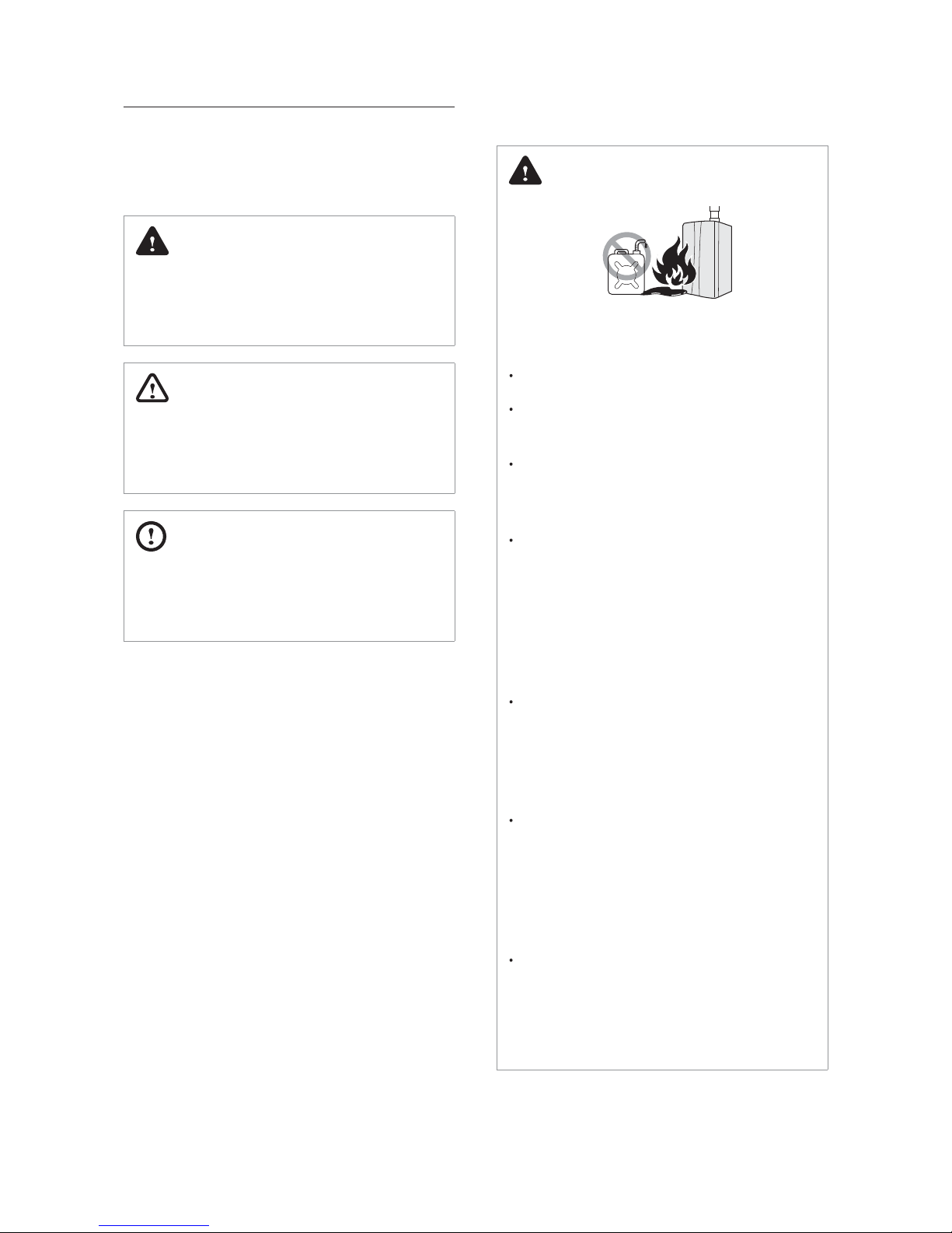
DANGER
If you smell gas:
Do not try to light any appliances.
Do not touch any electrical switches or
use landline phones.
From a neighbour’s phone, call
your gas provider and follow their
instructions.
If you cannot reach your gas provider,
call the re department.
Do not use or store ammable
products, such as petrol, solvents or
adhesives in the same room or area as
the water heater.
The water heater has a main burner
ame that can turn on at any time and
can ignite ammable vapours. Vapours
from ammable liquids can explode
and catch re, causing severe burns.
Vapours cannot be seen and are
heavier than air. They can travel long
distances along the ground and can
be carried from other rooms to the
water heater’s main burner ame by air
current.
Keep all ammable products far away
from the water heater and store them
in approved containers. Keep the
containers closed tightly and out of the
reach of children and pets.
1. Safety Information
4 Safety Information
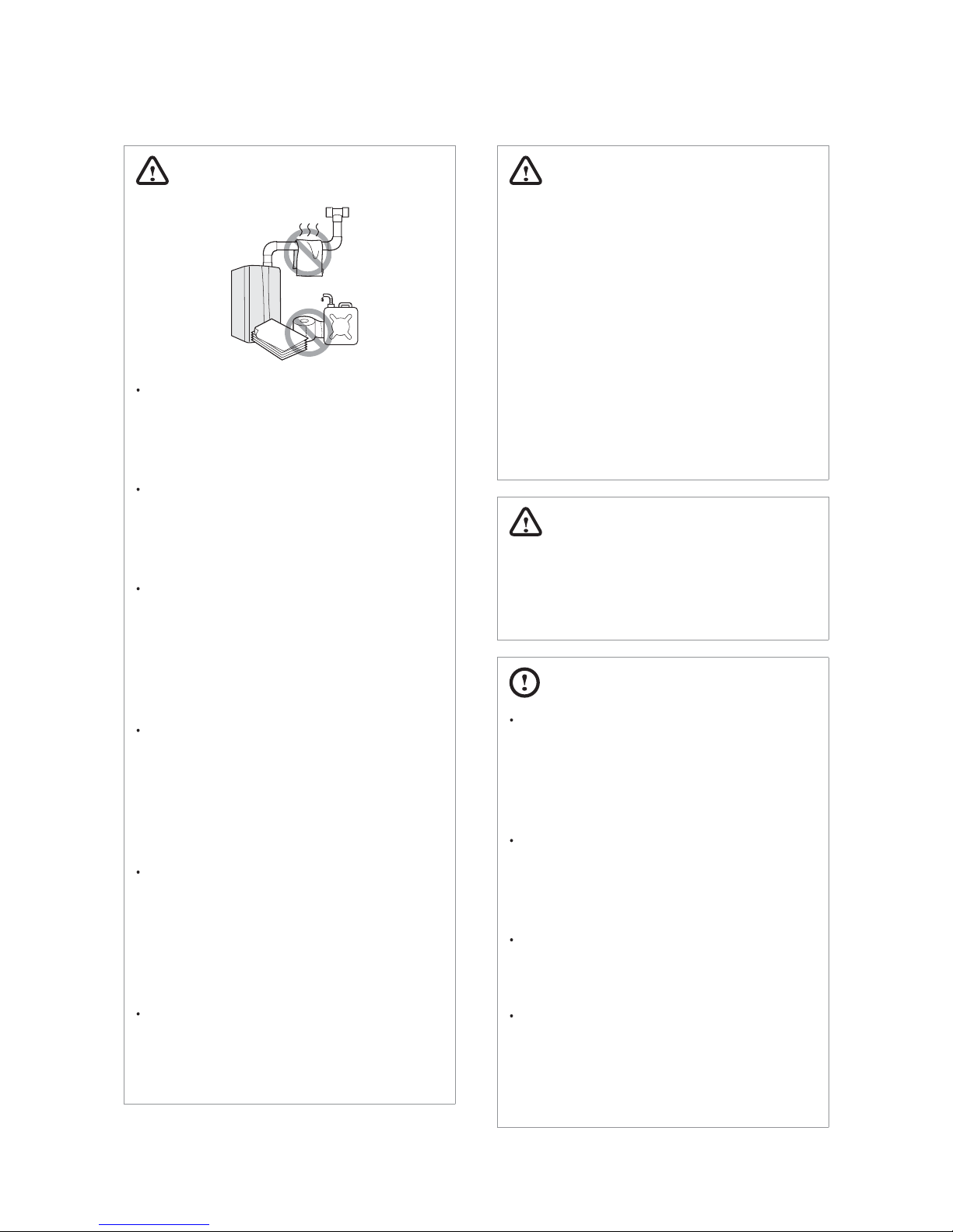
WARNING
Do not store or use petrol or other
ammable liquids near this water
heater.
Doing so may result in re or explosion.
Do not place combustibles, such as
newspapers or laundry, near the
water heater or ue system.
Doing so may result in a re.
Do not place or use hair sprays, spray
paints or any other compressed
gases near the water heater or
ue system, including the ue
termination.
Doing so may result in re or explosion.
Do not operate the water heater with
the front cover opened.
Doing so may result in re or carbon
monoxide (CO) poisoning, which may
result in property damage or personal
injury.
Do not operate this water heater
without proper ue system.
Doing so may result in re or carbon
monoxide (CO) poisoning, which may
result in property damage or personal
injury.
Do not touch the power cord or
internal components of the water
heater with wet hands.
Doing so may result in electric shock.
WARNING
This appliance can be used by children
aged from 8 years and above and
persons with reduced physical, sensory
or mental capabilities or lack of
experience and knowledge if they have
been given supervision or instruction
concerning use of the appliance in a
safe way and understand the hazards
involved. Children shall not play with
the appliance. Cleaning and user
maintenance shall not be made by
children without supervision.
WARNING
Disconnect the plug of the power supply
before carrying out any maintenance of
the appliance.
CAUTION
Do not turn on the water heater
unless the water and gas supplies
are fully opened.
Doing so may damage the water
heater.
Do not turn on the water if the cold
water supply shut-o valve is closed.
Doing so may damage the water
heater.
Do not use this water heater for
anything other than its intended
purpose, as described in this manual.
Do not remove the front cover unless
the power to the water heater is
turned o or disconnected.
Failure to do so may result in electric
shock.
5Safety Information
When servicing the controls, label all
wires prior to disconnecting them.
Failure to do so may result in wiring
errors, which can lead to improper or
dangerous operation. Verify proper
operation after servicing.
Do not use unapproved replacement
or accessory parts.
Doing so may result in improper or
dangerous operation and will void the
manufacturer’s warranty.
Do not place anything in or around
the ue terminals, such as a clothes
line, that could obstruct the air ow
in or out of the water heater.
This water heater has been approved
for use in the UK and Ireland only.
Using the water heater in any other
country will void the manufacturer’s
warranty.
General Installation Guidelines
Building regulations and Benchmark
Building regulations require that installation should comply
with manufacture’s instruction. It is therefore important that the
commissioning checklist is completed by the installer.
Benchmark places responsibilities on
both manufacturers and installers.
The purpose is to ensure that customers are provided with
the correct equipment for their needs, that it is installed,
commissioned and serviced in accordance with the
manufacturer’s instructions by competent persons and
that it meets the requirements of the appropriate Building
Regulations. The Benchmark Checklist can be used to
demonstrate compliance with Building Regulations and
should be provided to the customer for future reference.
Installers are required to carry out installation, commissioning
and servicing work in accordance with the Benchmark Code
of Practice which is available from the Heating and Hotwater
Industry Council who manage and promote the Scheme. Visit
www.centralheating.co.uk for more information.
Gas safety regulations
The water heater must be installed by an installer authorized by
the Ministry of Industry and it must be started up by an Ocial
Technical Assistance Service authorized by Navien.
All Gas Safe registered engineers carry an ID card with their
license number and a photograph. You can check your engineer
is registered by telephoning 0800 408 5500 or online at www.
gassaferegister.co.uk.
In GB, this must be carried out by a competent person* as stated
in the Gas Safety (Installation & Use) Regulations (as may be
amended from time to time).
In IE, this must be carried out by a competent person as stated
in I.S 813 “Domestic Gas Installations”.
The manufacturer will not accept any liability whatsoever for
loss, damage or injury arising as a result of failure to observe
the instructions for use, maintenance and installation of the
appliance.
*A competent person: One who works for a Gas Safe registered company
and holds current certicates in the relevant ACS modules.
Installation Instructions
Current legislation must be taken into account on installing
this appliance, and it must be installed in a place with suitable
ventilation.
In GB, the installation must be carried out by a Gas Safe
Registered installer. It must be carried out in accordance with
the current and relevant requirements of legislation and
guidance including:
The Gas Safety (Installation & Use) Regulations
The appropriate Building Regulations either The Building
Regulations, The Building Regulations (Scotland), The Building
Regulations (Northern Ireland)
Water Fittings Regulation and local byelaws
I.E.E. Wiring Regulations
Health and Safety Regulations
Where no specic instructions are given, reference should be
made to the relevant British Standard Code of Practice.
Standard Description
BS 5440: Part 1 Flues and ventilation: Flues
BS 5440: Part 2 Flues and ventilation: Air supply
BS 5546
Installation of hot water supplies for
domestic purposes
BS 6891 Installation of low pressure gas
BS 6644 Installation of gas-red hot water boiler
BS 6700
Installation of services supplying water for
domestic use
IGE/UP/10 Part
1 Edition 2
Installation of Gas appliances in
Commercial
6 Safety Information
Standard Description
BS 5482 Butane and propane installation
In IE, the installation must be carried out by a competent
Person and installed in accordance with the current edition of
I.S.831 ‘Domestic Gas Installations’, I.S.820 ‘Non-Domestic Gas
Installations’, the current Building Regulations and reference
should be made to the current ETCI rules for electrical
installations.
This water heater has been approved for use in the UK and
Ireland only. Using the water heater in any other country will
void the manufacturer’s warranty.
Liability and Responsibility
Our products are manufactured in compliance with the
requirements of the European applicable Directives. They
are therefore delivered with CE marking and all relevant
documentation. In the interest of customers, we are
continuously endeavoring to make improvements in product
quality. All the specications stated in this document are
therefore subject to change without notice.
The manufacturer will not accept any liability for loss, damage or
injury arising as a result of:
Failure to abide by the instructions on using the appliance.
Failure to regularly maintain the appliance, or faulty or
inadequate maintenance of the appliance.
Failure to abide by the instructions on installing the appliance.
Request to Installers
CAUTION
In order to use this water heater safely, read this instruction
manual carefully, and follow the installation instructions.
Failures and damage caused by erroneous work or work not as
instructed in this manual are not covered by the warranty.
Check that the installation was done properly in accordance
with this Installation Manual upon completion.
After completion if installation, be sure to hand the Operation
Manual to the customer upon lling in all of the required items.
Miscellaneous
Installation in hard water areas
In areas with hard water (hardness level exceeding 200 ppm),
it is important to install a scale reducer. The advice of the local
water authority should be sought.
Gas Conversion
The boiler is congured for natural gas. If LPG conversion is
required, use the conversion kit supplied with the water heater.
EC Conformity Declaration
006
3
Navien, hereby declares that the water heater models:
NPE-24AWE, NPE-32AWE, NPE-24SWE, and NPE-32SWE
to which this declaration refers, conform to and comply with
the essential requirements of the following applicable European
Standards and Directives.
Gas appliances: Directive 2009/142/EC Standards EN 437 and
EN 26
Water Heater Eciency: Directive 92/42/EEC
Regulation (EU) No. 814/2013
Regulation (EU) No. 812/2013
Low voltage: Directive 2006/95/EEC
Electro-magnetic Compatibility: Directive 2004/108/EEC
Noise: Standard EN 15036-1, EN-ISO 3743-1
Navien, manufactures its products using a Quality Assurance
system in compliance with Standard EN-ISO 9001:2000.
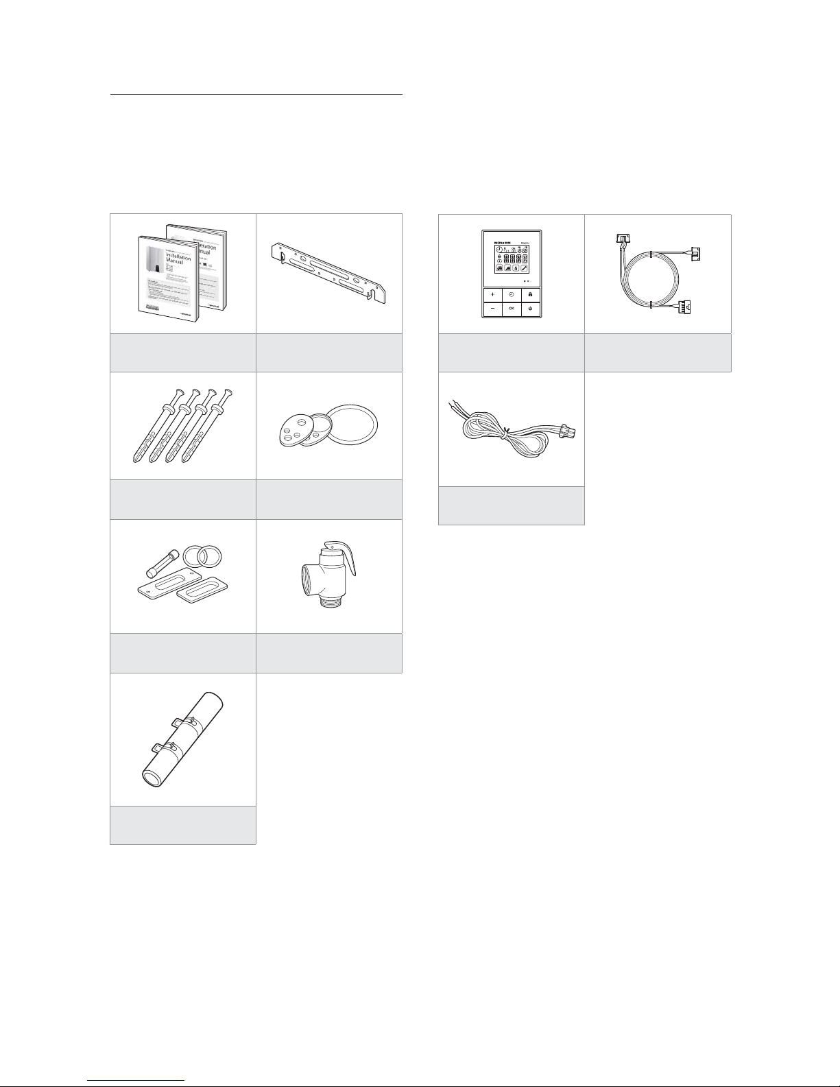
2.1 Items Included
When you open the box, you will nd the following items with
the water heater. Check the box for each of the following items
before installing the water heater.
Installation &
User’s Information Manual
Wall Mounting Bracket
Tapping Screws & Anchors Propane Gas Change Kit
Spare Parts Pressure Relief Valve
Condensate trap hose
2.2 Accessories
The following optional accessories are available for the water
heater:
Remote Controller
Ready-Link
Communication Cable
External Pump Connector
(<150W,1.5A)
2. About the Water Heater
7About the Water Heater

2.3 Specications
The following table lists the specications for the water heater. Additional specications about water, gas, electric, and air supplies
(ue system) appear in the Installation section.
Specications Unit NPE-24AWE NPE-24SWE NPE-32AWE NPE-32SWE
DHW input range kW 39.6 / 4.0 39.6 / 4.0 52.8 / 5.2 52.8 / 5.2
DHW output range kW 42.3 / 4.4 42.3 / 4.4 56.6 / 5.8 56.6 / 5.8
Eciency at maximum load %106.6 106.6 107.2 107.2
Eciency at minimum load % 111.0 111.0 111.0
111.0
DHW Flow Rate at 25°C temp. rise l/min 24.0 24.0 32.0 32.0
DHW Flow Rate at 40°C temp. rise l/min 15.0 15.0 20.0 20.0
Category II2H3P
Type Instantaneous hot water production
Appliance protection rating IP X5D
Min. DHW Working Pressure bar 1.0
Min. DHW Working Flow
l/min 1.8
Max. DHW Working Pressure bar 10.0
Adjustable DHW Temperature Range °C36 ~ 85
Dimensions (Width x Depth x Height) mm 440 x 336 x 695 440 x 336 x 695 440 x 336 x 695 440 x 336 x 695
Weight kg 34 30 37 34
Installation type Wall-mounted
Connection
diameter
Cold Water Inlet mm 22
Hot Water Inl
et mm 22
Ga
s Inlet mm 22
Power Supply
Main Supply 230V / 50Hz
Max. power
consumption
W 200W
Flue exhaust / Air intake system types B23, B33, B53, C13, C33, C43, C53, C63, C83
Flue exhaust / Air intake system diameters mm Coaxial Ø60/100 and Ø80/125 - Dual duct Ø80/80
Coaxial length
Ø60/100
Max. Horizontal m20
Max. Vertical m21
Equivalent elbow
length
Ø60/100
90° m2.4
45° m 1.2
Coaxial length
Ø80/125
Max. Horizontal m68
Max. Vertical m 70
Equivalent elbow
length
Ø80/125
90° m2.4
45° m 1.2
Equivalent length of adapter Ø60/1
00
Ø80/125
5.0m
Max. dual duct length Ø80/80 m 110
Equivalent elbow
length Ø80
90° m 2.2
45° m 1.4
8 About the Water Heater
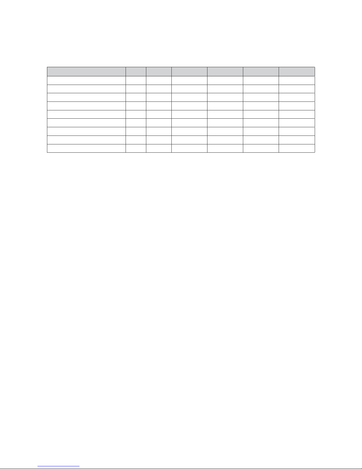
The following table lists the product information (EU regulation No 812/2013 and No 814/2013)
KD Navien Symbol Unit NPE-24AWE NPE-24SWE NPE-32AWE NPE-32SWE
Declared load prole XL XL XXL XXL
Water heating energy eciency class A A A A
Water heating energy eciency η
wh
% 102.6 105.8 105.4 106.7
Daily electrical consumption Q
elec
kWh 0.100 0.104 0.111 0.111
Annual electrical consumption AEC kWh 41 57 24 24
Daily fuel consumption Q
fuel
kWh 18.106 17.380 23.001 22.721
Annual fuel consumption AFC GJ 14 14 18 18
Sound power level, indoors L
WA
dB 56 56 58 58
Emissions of nitrogen dioxide NOx mg/kWh 25 25 23 23
Specic precaution
Read the user’s information and installation manual before the application is assembled, installed or maintained.
9About the Water Heater
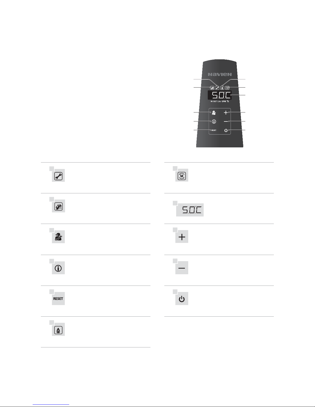
2.4 The Front Panel
The front panel allows you to adjust the water temperature and
view the operating status or error codes. Remove the protective
sheet from the front panel before using it.
a
Error
g
Master Unit
A code will appear on the display Cascade operation
b
Hot Water Recirculation
h
Display
Recirculation Mode
c
Diagnostics button
i
Up button
For installers only Increases the temperature
d
Information button
j
Down button
Shows basic information Decreases the temperature
e
Reset button
k
Power button
Resets the water heater (When an error occurs)
Turns the water heater on or o
f
Combusting
When the gas burner is on
a
b
c
d
e
f
g
h
i
j
k
10 About the Water Heater
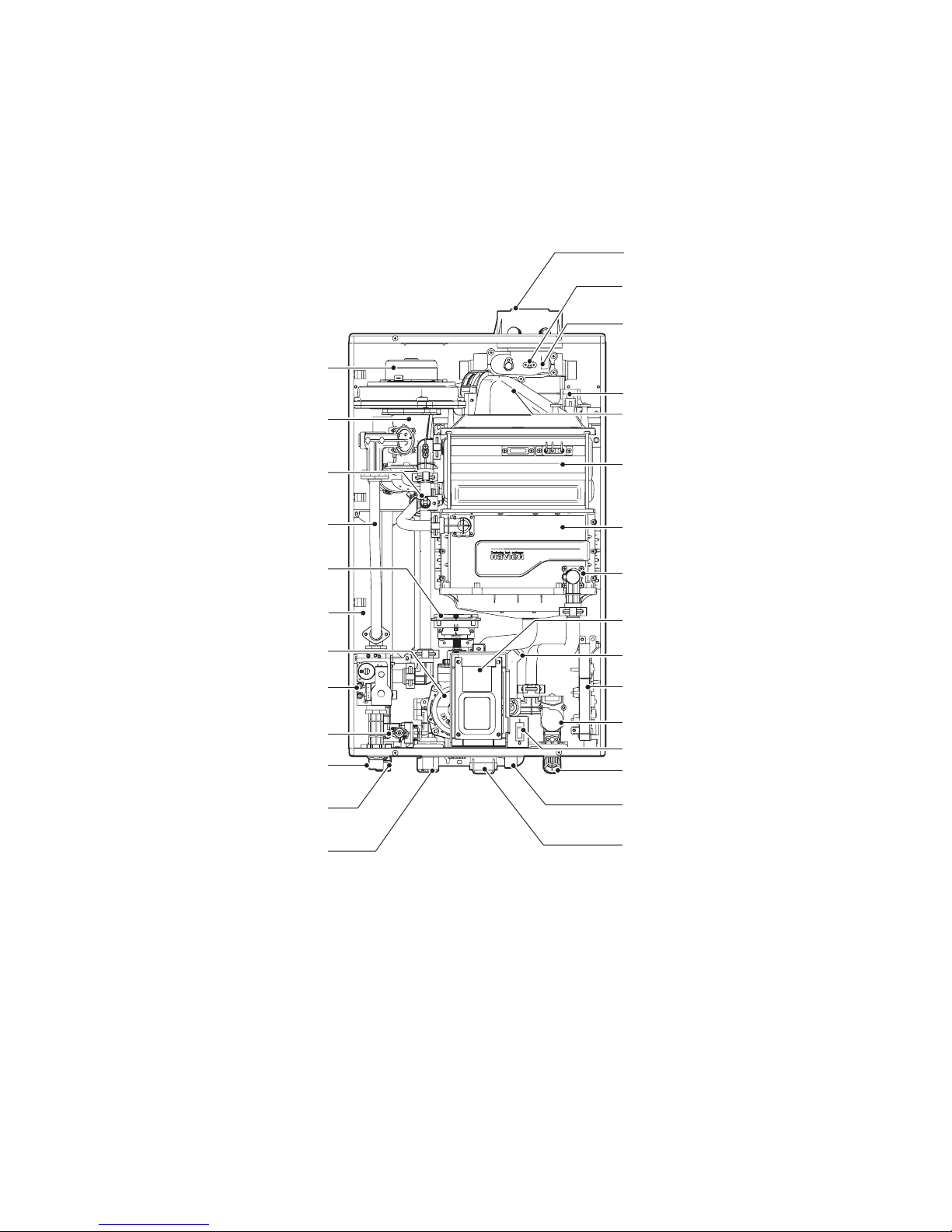
2.5 Components
The following diagram shows the key components of the water heater. Component assembly diagrams and particular parts lists are
included in the Appendixes.
Coaxial Adapter
Exhaust Limit Temperature Sensor
Flue Duct
Ignition Transformer
Burner
Primary Heat Exchanger
Secondary Heat Exchanger
Flow Sensor
Condensate Trap
Front Panel
PCB Box
Water Adjustment Valve
Water Inlet Filter
Condensate Drain Fitting
Condensate Drain Lid
Fan Moto r
Dual Venturi
Gas Pipe
APS (Air Pressure Sensor)
Buer Tank
Circulation Pump
Gas Valve
Gas Inlet Fitting
DHW Supply Fitting
2-Way Valve
Recirculation Inlet Fitting
[NPE-24AWE/32AWE]
High Limit Switch
Power Switch
11About the Water Heater
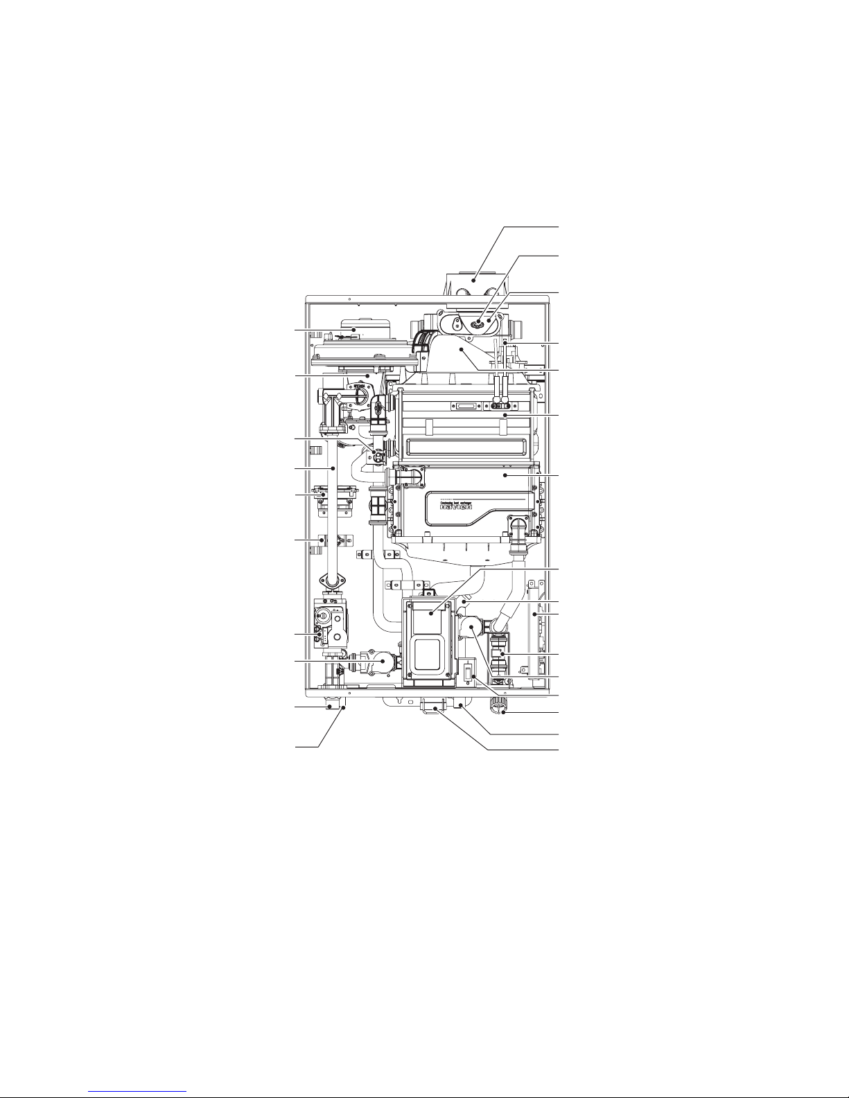
Coaxial Adapter
Exhaust Limit Temperature Sensor
Flue Duct
Ignition Transformer
Burner
Primary Heat Exchanger
Secondary Heat Exchanger
Flow Sensor
Condensate Trap
Front Panel
PCB Box
Mixing Valve
Water Inlet Filter
Condensate Drain Fitting
Condensate Drain Lid
Fan Motor
Dual Venturi
Gas Pipe
APS (Air Pressure Sensor)
Gas Valve
Free
ze Protection Switch
Gas Inlet Fitting
Water Adjustment Valve
DHW Supply Fitting
[NPE-24SWE/32SWE]
High Limit Switch
Power Switch
12 About the Water Heater
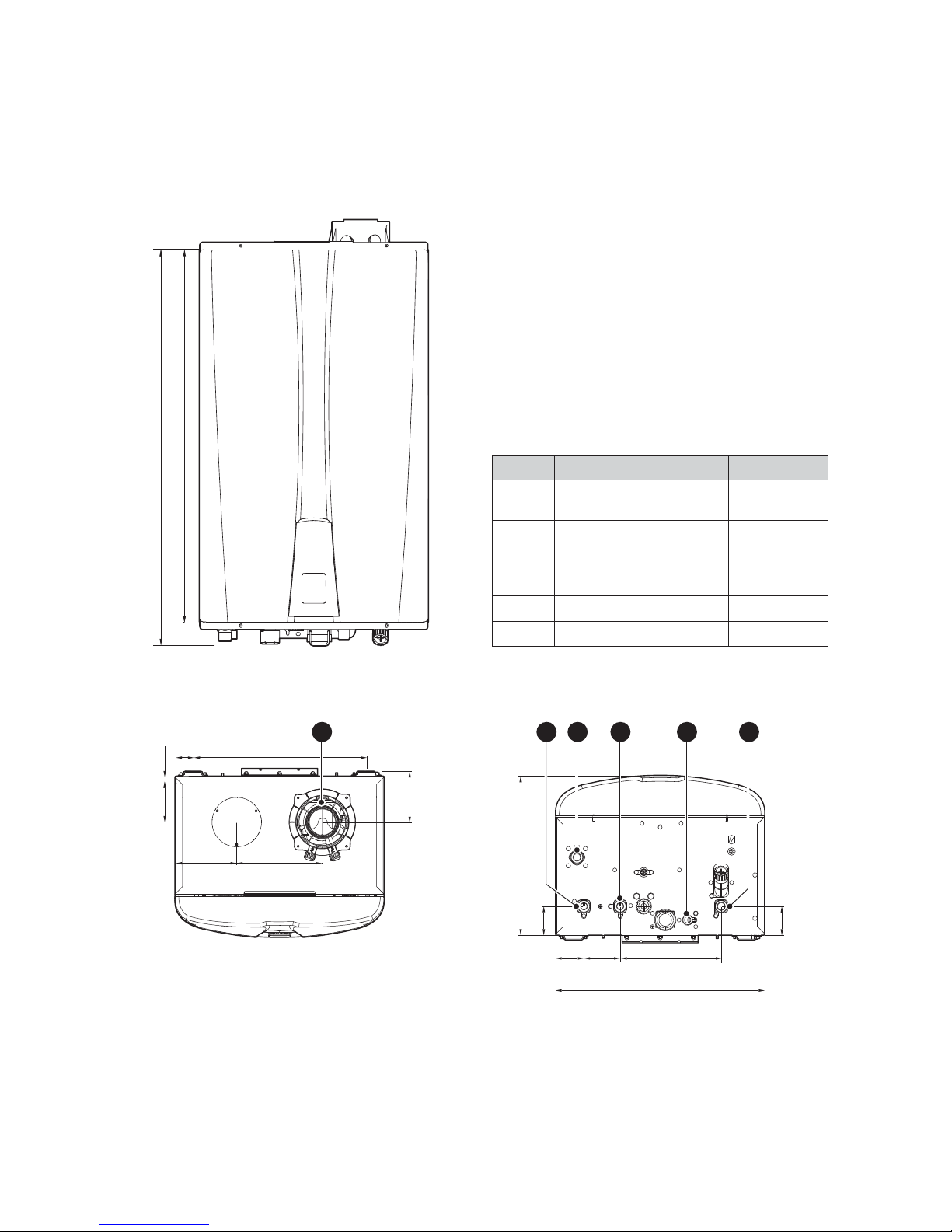
2.6 Dimensions
The following diagrams show the dimensions of the water heater and the table lists the supply connections.
695 mm
731 mm
Supply Connections
Description Diameter
AFlue Exhaust / Air Intake
Ø60/100
Ø80/125
BHot Water Outlet 22 mm
C Recirculation Inlet 22 mm
DCold Water Inlet 22 mm
EGas Inlet 22 mm
F Condensate Outlet 15 mm
Overhead View
77 mm
170 mm
115 mm
10 mm
38 mm 364 mm
67 mm
A
Bottom View
336 mm
60 mm
77 mm 212 mm
440 mm
61 mm
61 mm
B
E C F D
[NPE-24AWE/32AWE]
13About the Water Heater
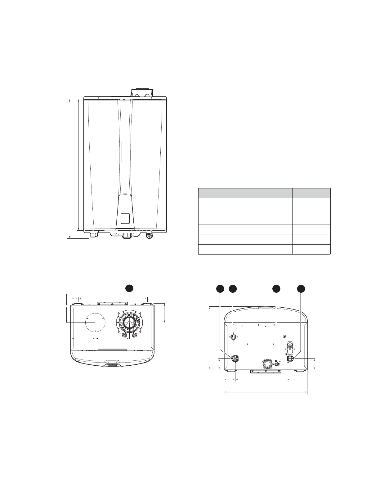
695 mm
731 mm
Supply Connections
Description Diameter
AFlue Exhaust / Air Intake
Ø60/100
Ø80/125
BHot Water Outlet 22 mm
CCold Water Inlet 22 mm
DGas Inlet 22 mm
E Condensate Outlet 15 mm
Overhead View
77 mm
170 mm
115 mm
10 mm
38 mm 364 mm
67 mm
A
Bottom View
336 mm
60 mm
289 mm
440 mm
61mm
61mm
B
E CD
[NPE-24SWE/32SWE]
14 About the Water Heater

15
3.1 Choosing an Installation Location
When choosing an installation location, you must ensure that
the location provides adequate clearance for the water heater,
adequate ue and drainage options, and sucient access to gas,
water, and electrical supplies.
Carefully consider the following factors when c
hoosing an
installation location:
Compliance Requirements
This water heater must be installed by qualied personnel
in compliance with the applicable Laws and Regulations.
In general, these Laws and Regulations are the Basic Gas
Installation Standards, the Heating, Air
Conditioning and
Domestic Water Installation Regulation and all other local
regulations.
Access to Utilities
Water–the installation location should be near where the
domestic water supply enters the building.
Gas–the installation location should be near where the gas
supply enters the building.
Electricity–the installation location should be near where the
electrical supply enters the building.
Humidity and Contact with Water
When installing the water heater, avoid places with excessive
humidity. The water heater has electric gas ignition components.
Water
spray or droppings can get inside the water heater and
damage the ignition system. The water heater must be installed
in a way to ensure that the gas ignition system components
are protected from water (dripping, spraying, rain, etc.) during
operation and service.
If the water heater
is installed in a very humid room (a shower
room or bathroom, for example), the Low Voltage regulation
and the Technical Building Code must be observed for correct
installation.
Proximity to Fixtures and Appliances
Install the water heater near xtures that deliver or
use hot
water, such as bathroom, kitchen, and laundry room faucets.
Select a location that minimizes the water piping required
between major xtures. If the distances are long or if the user
requires “instant“ hot water, installation of a recir
culation line
which circulates domestic hot water back to the water heater
from the furthest xture is recommended. Insulate as much of
the hot water supply and recirculation lines as possible.
Adequate Drainage
The water heater produces a signi
cant amount of condensate
during operation. This condensate must be removed from
the water heater, and suitably treated if national legislation
so requires. The water heater should be located near a
suitable drain and where damage from a possible leak
will be minimal.
Installing the water heater in a location
without a drain will void the warranty and Navien will not
be responsible for water damage that occur as a result.
For more information about condensate drainage, refer to
“3.5 Connecting the Condensate Drain Line” on page 2
7.
The water heater must be located in an area where leakage of
the unit or connections will not result in damage to the area
adjacent to the appliance or to lower
oors of the structure.
When such locations cannot be found, installation of an
adequately drained drain pan under the water heater is highly
recommended. When installing the drain pan, ensure that the
installation does not restrict combustion air
ow.
Adequate Flue and Ventilation
Select a location that requires minima
ue. Consider ue
restrictions caused by windows, doors, air intakes, gas meters,
foliage, and other buildings. For more information about
ue
system, refer to “3.6 Flue System” on page 28.
To ensure adequate ue and ventilation, follow these guidelines:
Maintain proper clearances from any openings in the building.
Install the water heater with a minimum clearance of 300 mm
above an exterior grade or as required by local codes.
Do not enclose the ue termination.
Install the exhaust ue in an area that is free from any
obstructions, where the exhaust will not accumulate.
Do not install the water heater where moisture from the
exhaust may discolour or damage walls.
Do not install the water heater in bathrooms, bedrooms or
any other occupied rooms that are normally kept closed or
not adequately ventilated.
The requirements and recommendations stipulated in the
Regulation for Heating Installations in Buildings (RITE) and any
other applicable legislation in this
eld must be observed.
No speci
c ventilation is required in the room the water
heater is installed in. If it is installed in a cupboard or
compartment, no speci
c ventilation is required, providing the
aforementioned dimensions are observed. The requirements
and recommendations stipulated in the Regulation for Heating
Installations in Buildings (RITE) and any other applicable
legislation in this
eld must be observed.
3. Installing the Water Heater
Installing the Water Heater
16 Installing the Water Heater
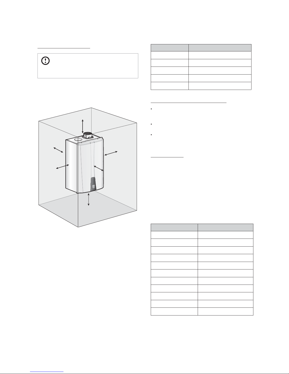
Adequate installation clearances
CAUTION
Do not install the water heater on carpeting.
Install the water heater in an area that allows for service and
maintenance access to utility connections, piping, lters,
and traps. Based on the installation location, ensure that the
following clearances are maintained:
Top
Bottom
Front
Clearance from:Indoor Installation
Top 250 mm minimum
Front 100 mm minimum
Bottom 300 mm minimum
Back 20 mm minimum
Sides 76 mm minimum
Clean, debris and chemical-free combustion air
Do not install the water heater in areas where dust and debris
may accumulate or where hair sprays, spray detergents,
chlorine or similar chemicals are used.
Do not install the water heater in areas where petrol or other
ammables are used or stored.
Ensure that combustible materials are stored away from the
water heater and that hanging laundry or similar items do not
obstruct access to the water heater or its ue system.
About Water Quality
Proper maintenance of the water heater is required when water
quality does not meet standards. Damage caused by poor water
quality is not covered under warranty. The following table shows
the maximum contaminant levels allowed. If you suspect that
your water is contaminated in any way, discontinue use of the
water heater and contact an authorized technician or licensed
professional.
Installation in hard water areas
In areas with hard water (hardness exceeding 200 ppm), it is
important to install a scale reducer. The advice of the local water
authority should be sought.
Contaminant Maximum Allowable Level
Total Hardness Up to 200 mg/l (12 grains/gallon)
Aluminum 0.05 to 0.2 mg/l
Chloride Up to 250 mg/l
Copper Up to 1.0 mg/l
Iron Up to 0.3 mg/l
Manganese Up to 0.05 mg/l
pH 6.5 to 8.5
Sulfate Up to 205 mg/l
Total Dissolved Solids (TDS) Up to 500 mg/l
Zinc Up to 5 mg/l
Chlorine Up to 4 mg/l
Sides
Back
Sides
17Installing the Water Heater
3.2 Mounting the Water Heater to the
Wall
Navien NPE-AWE/NPE-SWE water heaters come with an upper
mounting bracket that is pre-drilled at 400 mm on centre for
easy installation on standard wall studs. If the strength of the
wall is insucient or if the framing is non-standard or uneven,
reinforce the area before installing the water heater. Avoid
installation on common walls as the unit will make some
operational noises while it is running.
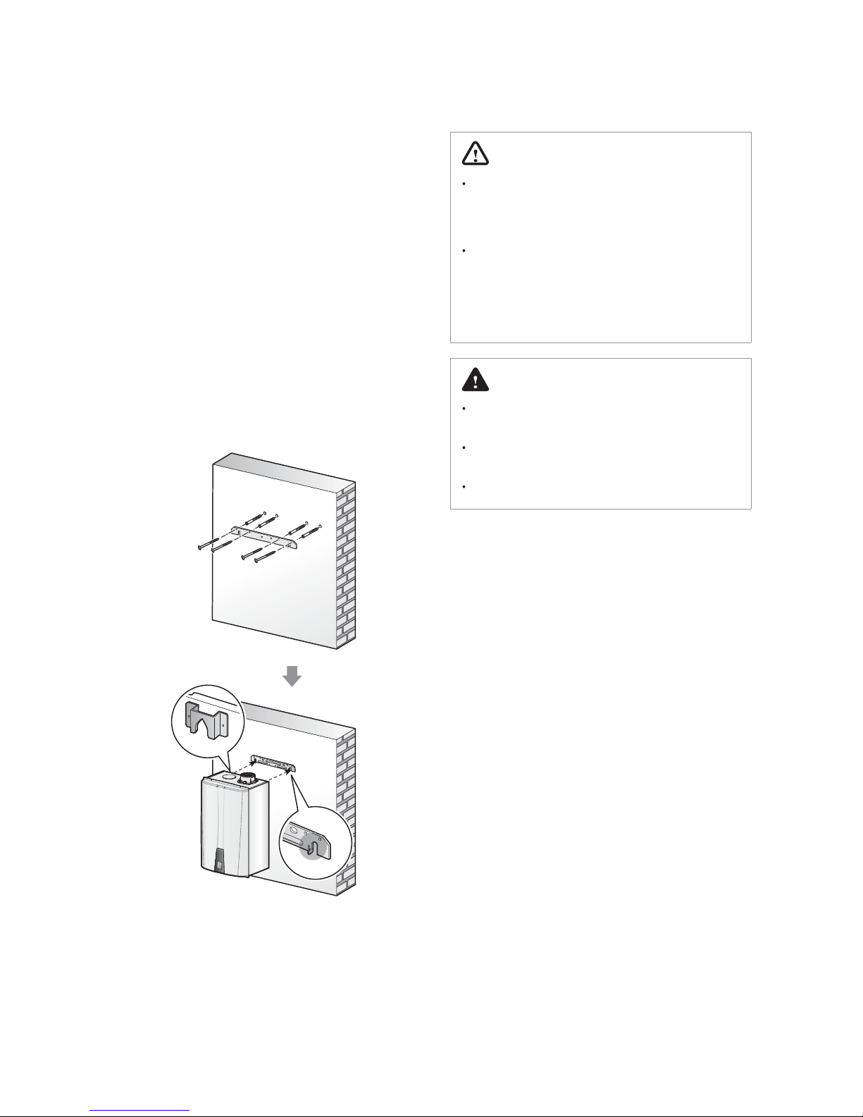
To mount the water heater to the wall:
1. Ax the bracket securely to the wall and ensure that it is
level and that it can support the weight of the water heater.
2. Align the grooves on the back of the water heater with
the tongues on the mounting bracket and hang the water
heater on the bracket.
When mounted with the mounting bracket, the water
heater will have a 20 mm clearance from the back of the
wall.
WARNING
The water heater is heavy. Always lift the unit with
assistance. Be careful not to drop the water heater while
lifting or handling it to avoid bodily injury or damage to
the unit.
Do not rest the water heater on the bottom end after
removing it from the shipping carton. Doing so may
result in excessive pressure on protruding pipes and
result in product damage. If you must put the water
heater down, lay it on its back or
put it inside the
protective shipping base.
DANGER
The water heater must be mounted on a suitable wall
that can support its weight and prevent explosion or re.
Do not install the water heater near paper or other
ammable objects.
Do not install the water heater near domestic waste.
18 Installing the Water Heater
3.3 Connecting the Gas Supply
WARNING
If a gas type other than the one specied on the water
heater reference plate is used, it could cause a re or
even an explosion.
It is important to ensure that the gas supply is suitable
for the type and capacity of the water heater.
Thoroughly check the seal and draining of the entire
installation, as a gas leak could cause serious damage.
DANGER
Gas leaks can cause explosions resulting in serious
personal and material damage.
Keep all doors and windows open while you are bleeding
the gas pipes and put out any cigarettes, ames or other
possible source of ignition.
For the installation of any type of gas, the installer must be
authorised by the Ministry of Industry and strictly follow the
applicable Gas Regulations. The gas installation must comply
with the Gas Installation Regulation.
However, the following recommendations must be complied
with, at the least:
Before installing the gas pipes, check the type of gas is
compatible with the water heater.
Check that the gas meter in the home can measure the rate of
gas supply required.
The gas pipe diameter is not determined by the water heater
connection. It should be calculated in accordance with its
length and consequently its pressure drop.
The pipes must be directly connected to the main gas supply
pipe, not connected in parallel to other gas appliances.
Check there are no leaks from the installation.
The gas supply company is solely responsible for connecting
the gas meter to the gas installation.
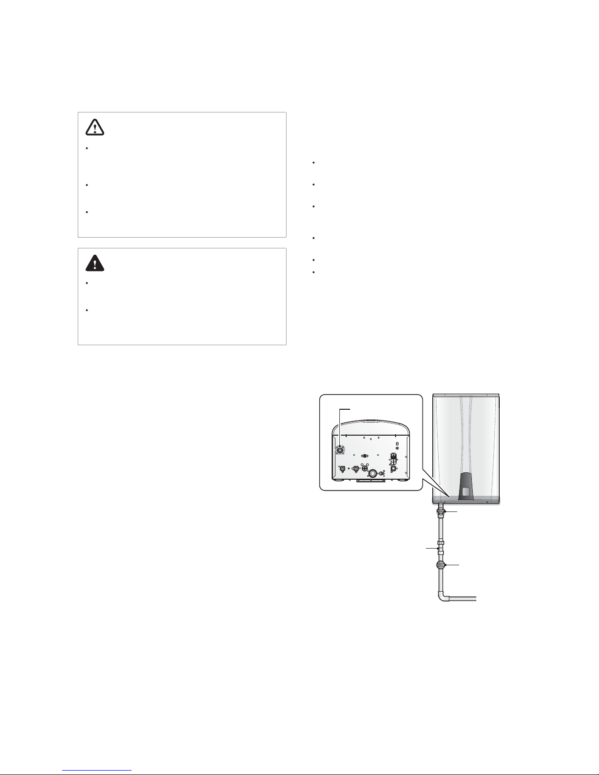
To connect the gas supply:
1. Connect the gas supply pipe to the connection located on
the underside of the appliance.
2. After completing the gas installation, check there are no
leaks and bleed the air from all the pipes, following the
procedures described in the applicable standards to this
respect.
Gas Shuto Valve
Gas Pipe
Union
Bottom View
Gas Inlet Adapter
19Installing the Water Heater
3.3.1 Gas Pipe Material
WARNING
The water heater must be left running for 10 minutes
before checking the gas pressure, to obtain thermal
equilibrium.
The gas installation pipes must be made of suitable materials
and comply with the applicable legislation to this respect.
The gas connection must be made using a rigid pipe, inserting
a shut-o valve between the water heater and the pressure
regulator.
All the pipes must be suitably xed in place.
3.3.2 Propane Gas Installations (LPG)
DANGER
Thoroughly check the seal and the drainage of the entire
installation, as a gas leak could cause serious damage.
If a propane-red water heater is installed in an interior
room or compartment underground, one side of the
building must be open to the exterior.
If a gas tank is used, it must be installed in a cool,
shaded place away from direct sunlight. It must also
be thoroughly secured to prevent it from tipping over,
which could cause an explosion.
If the water heater is used with propane, a gas regulator suitable
for this type of gas must be installed. The connection and
installation must be made in accordance with the applicable
regulations and standards at the time of installation.
Note
The output pressure of the pressure regulator must be
in accordance with Standard EN 437.
3.3.3 Measuring the Inlet Gas Pressure
WARNING
The water heater cannot function properly without
sucient inlet gas pressure. Measuring the inlet gas
pressure should be performed by a licensed professional
only.
The inlet gas pressure must be maintained between 17 mbar
and 25 mbar for natural gas and between 25 mbar and 35 mbar
for liqueed propane.
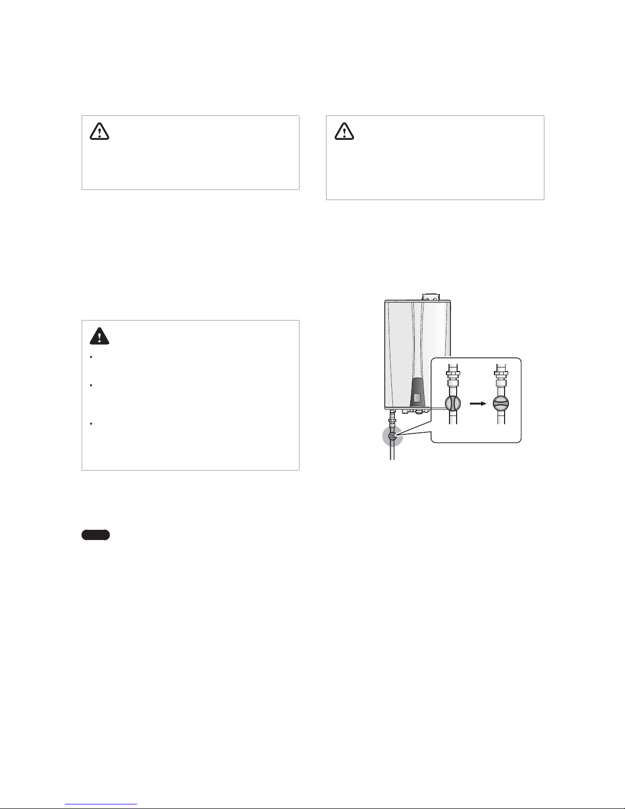
To measure the inlet gas pressure:
1. Shut o the manual gas valve on the gas supply line.
Gas Valve
Opened
Closed
2. Open a hot water faucet. The water heater should turn on
and the gas in the gas supply line will be purged.
20 Installing the Water Heater
3. Leave the faucet on until the water heater shuts down due
to a lack of gas supply, and then turn o the hot water
faucet.
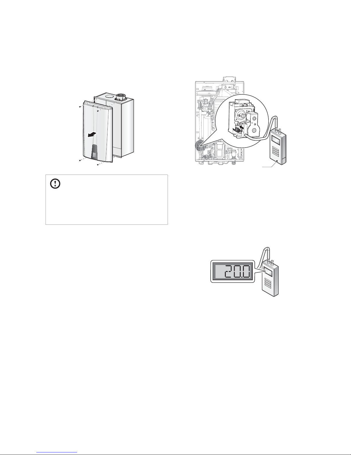
4. Remove the front cover by loosening the four Phillips head
screws securing it to the case.
CAUTION
Ensure that no cables are in the way before folding down
the PCB assembly. If the assembly is stuck, do not force
it. Doing so may damage the cables and result in serious
malfunctions. Check again to ensure that no cables or any
other parts are in the way before you proceed.
5. Loosen the screws indicated in the gure below and
connect a manometer to the pressure port. Reset the
manometer to zero before use.
Digital pressure
manometer
6. Re-open the manual gas valve and check for leaks.
7. Open multiple xtures that have high ow rates, such as
bathtub and shower faucets, to ramp the water heater up to
its maximum ring rate.
8. When the water heater reaches its maximum ring rate,
check the inlet gas pressure reading on the manometer.
The gas pressure must fall within the ranges specied on
page 19.
21Installing the Water Heater
3.4 Connecting the Water Supply
When connecting the water supply, follow these guidelines:
Do not remove the factory installed recirculation inlet cap
unless a return line is connected to this tting. Water leakage
will occur if this cap is loose or missing ("A" model only).
Use only pipes, ttings, valves, and other components, such as
solder, that are approved for use in potable water systems.
Tighten the water heater connection valves with care to avoid
damage.
We recommend using unions and manual shut-o valves on
the cold water inlet, DHW outlet, and recirculation water inlet.
Strive to make the hot water piping system as short as
possible, to deliver hot water to the xtures more quickly.
To conserve water and energy, insulate all water piping—
especially the hot and recirculation water lines. Never cover
the drain or pressure relief valve. If the water heater is installed
in a closed water supply system, such as one having a
backow preventer in the cold water supply line, means shall
be provided to control thermal expansion. Contact the water
supplier or local plumbing inspector for information about
how to control this situation.
After installing the water heater, clean the inlet water lter
that is located inside the cold water inlet, and then test the
water heater for proper ow and inspect for leaks. Instruct
the water heater owner that the lter must be cleaned
periodically to maintain proper water ow.
WARNING
Tighten the water heater water connections, taking care
not to damage them. Do not force the tube connections
excessively, as this could damage the connections and
cause leaks.
Any dirt in the tubes could reduce water heater eciency
and cause it to malfunction.
Any pipes exposed to the elements or which could freeze
in winter must be insulated with suitable insulating
material.
CAUTION
Failure to follow the instructions provided in this section
will void the warranty and may result in property damage,
re or serious injury.
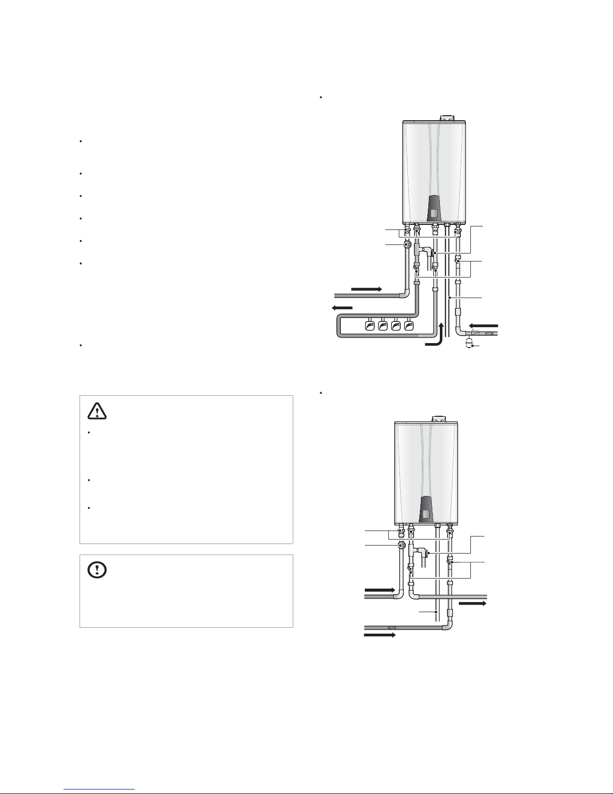
The following is a typical water piping example for NPE24AWE/32AWE models.
Pressure
Relief Valve
Union
Full port
Gas Valve
Gas Supply
Expansion
Tan k
Hot Water Supply
Recirculation Line
Shuto Valve
Condensate Drain
Cold Water
Supply
[NPE-24AWE/32AWE]
The following is a typical water piping example for NPE24SWE/32SWE models.
Pressure
Relief Valve
Shuto Valve
Hot Water
Supply
Union
Full port
Gas Valve
Gas Supply
Cold Water
Supply
Condensate Drain
[NPE-24SWE/32SWE]
 Loading...