

Navien NPE-180S, NPE-210A, NPE-210S, NPE-240S, NPE-240A Conversion Manualline
123
4
Condensing Water Heater
Gas Conversion
Guide
Model
NPE-180A/210A/240A
NPE-150S/180S/210S/240S
This water heater is congured for Natural Gas from the
factory. If conversion to Propane Gas is required, the
conversion kit supplied with the water heater must be used.
WARNING
This conversion kit shall be installed by a qualied service
agency* in accordance with Navien’s instructions and
all applicable codes and requirements of the authority
having jurisdiction. The information in these instructions
must be followed to minimize the risk of re or explosion
or to prevent property damage, personal injury or death.
The qualied service agency is responsible for the proper
installation of this kit. The installation is not proper and
complete until the operation of the converted appliance
is checked as specied in the manufacturer’s instructions
supplied with the kit.
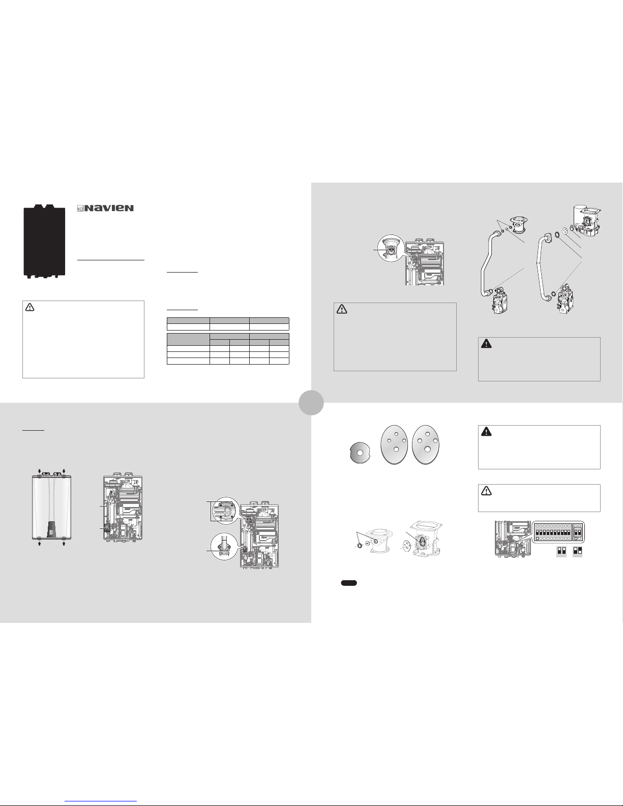
Procedure:
1. Turn o both gas and water supply to the water heater.
2. Using a Phillips hand screwdriver, remove 4 screws (2 from
the top and 2 from the bottom) of the front cover assembly
to gain access to the internal components. See Figure 1 for
illustration of the front cover on the unit.
Gas Valve
Gas Inlet
Pipe
Figure 1.
NPE Series Front cover
Figure 2. NPE Series
Internal Components
3. Once the front cover is removed, place it in a safe
location to prevent accidental damage. With the internal
components exposed, locate the gas inlet pipe and the Gas
Valve near the left side of the unit which are highlighted in
Figure 2.
6. Once the Gas Orice is exposed, remove the two screws
that hold the part in place. Remove the Gas Orice from
its housing and prepare the new Gas Orice for the LP
conversion for installation.
Remove two (2)
screws here
Figure 4. Access to Gas Orice in Fan Assembly
WARNING
●
DO NOT adjust or attempt to measure gas valve outlet
pressure. The gas valve is factory-set for the correct
outlet pressure. This setting is suitable for natural gas and
propane, requiring no eld adjustment.
●
Attempting to alter or measure the gas valve outlet
pressure could result in damage to the valve, causing
potential severe personal injury, death or substantial
property damage. Navien water heaters are shipped
ready to re natural gas ONLY.
LP
NPE-150S NPE-180A/ 210A/ 240A/ 180S/ 210S/ 240S
NG
Figure 6. Orice identication
7. Remove the Gas Orice, ensure that the packing is properly
seated inside the port, and then install the new Gas Orice
for use with LP gas. Ensure that the Orice is properly
seated on the packing inside the port before proceeding
to the next step.
Packings
Packing
8. Replace the gas inlet pipe to its original position and use
all screws to secure all connections.
Note
Do not overtighten as this may damage or
crack the components.
* A qualied service agency is any individual, rm, corporation or
company which either in person or through a representative is
engaged in and is responsible for the connection, utilization, repair
or servicing of gas utilization equipment or accessories; who is
experienced in such work, familiar with all precautions required, and
has complied with all of the requirements of the authority having
jurisdiction.
In Canada: The conversion shall be carried out in accordance
with the requirements of the provincial authorities having
jurisdiction and in accordance with the requirements of the
CAN‐B149.1 and CAN1‐B149.2 Installation Code.
Tools Required:
●
Phillips Screwdriver
●
Flathead Screwdriver
●
5
/32 in or 4 mm Allen Wrench
●
Combustion Analyzer or Dual Port Manometer
●
Gas Leak Detector
Included Items:
●
Gas Orice (refer to below table)
Model NG LP
NPE-150S Ø 6.30 Ø 5.10
Model
NG LP
1STAGE 2STAGE 1STAGE 2STAGE
NPE-180A/NPE-180S Ø 4.80 Ø 5.95 Ø 3.80 Ø 4.70
NPE-210A/NPE-210S Ø 6.10 Ø 6.30 Ø 4.50 Ø 4.80
NPE-240A/NPE-240S Ø 6.10 Ø 6.30 Ø 4.50 Ø 4.80
Table 1. Orice Size
●
Gas Pressure and Conversion Kit Number Labels
4. Use a Phillips screwdriver to remove the two screws at
Location A - the connection below the Gas Valve where it
connects to the pipe. See Figure 3 for reference. Once the
screws are removed, carefully separate the pipe from the
Gas Valve.
5. Once the gas inlet pipe is detached from the Gas Valve, nd
Location B - the connection above the Gas Valve where it is
attached to the Fan Motor Assembly. Carefully remove the
four screws by hand using a Phillips screwdriver and pull
the Gas Valve away from the Fan Assembly to access the
Gas Orice.
Location B:
Remove four (4)
screws here
Location A:
Remove two (2)
screws here
Figure 3. Detaching Gas Valve from
Gas Inlet Pipe and Fan Motor Assembly
O-ring
Gas Orice
Packing
O-ring
Gas Orice
Packing
<NPE-150S> <NPE-180A/ 210A/ 240A/
180S/ 210S/ 240S>
Figure 5. Exploded view of Gas assembly
DANGER
See Figure 5. Inspect the O-ring between the gas valve and
gas valve inlet adapter whenever they are disassembled.
The O-ring must be in good condition and must be
installed. Failure to comply will cause a gas leak, resulting in
severe personal injury or death.
DANGER
Inspect the O-ring between the gas valve and gas valve
inlet adapter whenever they are disassembled. The O-ring
must be in good condition and must be installed. Failure to
comply will cause a gas leak, resulting in severe personal
injury or death.
9. Set the Front Panel Dip switch according to the gas type.
WARNING
Be sure to turn o the power before changing the DIP
switch setting.
1 2 NG1 2
LP
1 2 3 1 2 4 5 6 7 8 9 10
ON ON
10. Turn on the gas and water supply to the water heater.
Downloaded from https://GadgetsGo.com
567
8
DANGER
●
When conversion is required, be sure to set the Front
Panel DIP switches according to the supply gas type.
●
Failure to properly set the DIP switches could cause
carbon monoxide poisoning, resulting in severe personal
injury or death.
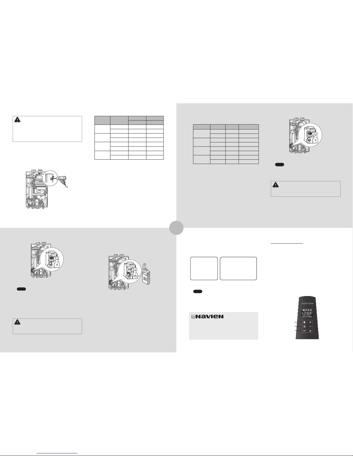
11. Measure and adjust the gas/air ratio.
Option 1. Using Combustion Analyzer (recommended)
a. Loosen the screw, rotate the plate and remove the
gasket to access the emissions monitoring port as
shown in Figure 7.
b. Insert the analyzer into the port (Figure 7).
Figure 7
Figure 8. Set Screw Location
Note
The set screw is located behind the screw-on
cover. This must be removed rst.
d. Fully open several hot water xtures and set the water
heater to operate at 2-stage MAX mode (refer to
page 8). Measure the CO
2
value at high re.
If the CO2 values do not match Table 2 at high re, do
not adjust the gas valve. Check for the proper Gas
Orice.
DANGER
Improper gas valve settings can cause severe personal
injury, death or substantial property damage.
b. Connect a manometer to the oset pressure port. For
dual port manometers, use the positive pressure side.
Model Kit Part No. Gas Type Oset
NPE-150S
NAC-N6 LP -0.03 in ± 0.01 in
NAC-L6 NG -0.04 in ± 0.01 in
NPE-180A
NPE-180S
NAC-01 LP -0.03 in ± 0.01 in
NAC-100 NG -0.04 in ± 0.01 in
NPE-210A
NPE-210S
NAC-02 LP -0.02 in ± 0.01 in
NAC-200 NG -0.04 in ± 0.01 in
NPE-240A
NPE-240S
NAC-03 LP -0.02 in ± 0.01 in
NAC-300 NG -0.04 in ± 0.01 in
Table 3. Oset value for low re
c. Fully open a hot water xture and set the water heater
to operate at 1-stage MIN mode (refer to page 8).
Measure the oset value at low re and compare it to
the values in Table 3. If the oset value is out of range,
the gas valve set screw will need to be adjusted.
If adjustment is necessary, locate the set screw as
shown in Figure 10. Using a
5
/32 in or 4 mm Allen
wrench, turn the set screw no more than
1
/4 turn
clockwise to raise or counterclockwise to lower the
oset value.
12. Once the CO
2
or oset values have been conrmed,
apply the included conversion stickers to show that the
appliance has been converted to propane gas. Place this
labels adjacent to the rating plate as shown in Figure 11.
Orice Size / Injecteur:
Min. 4.5 mm to Max. 4.8 mm
This unit has been
converted to Propane fuel
Cet appareil a ete converti au Propane
Manifold Gas Pressure /
Pression à la tubulure d’alimentation:
Min. -0.02 to Max. -0.66 inches WC
BTU Input / Debit calorique:
Max. 180,000 - Min. 19,900 BTUh
Conversion Kit No.: NAC-02
Inlet Gas Pressure / Pression d'entrée du gaz:
Min. 8.0 to Max. 13.0 inches
with Kit No. ________________________
This water heater was converted on
(name and address of organization making
this conversion, who accepts responsibility
for the correctness of this conversion)
______/______/______ to ____________ gas
by _________________________________
_________________________________
Figure 11. Proper Placement of Gas Conversion Labels
Note
Manifold Gas Pressure ratings can change due
to updated orice sizes. Please conrm new
manifold pressures approved by CSA before
production of gas conversion labels.
Water
Heater
Fuel
High re Low re
%CO
2
%CO
2
NPE-150S
NG 8.9 9.5
LP 10.2 10.8
NPE-180A
NPE-180S
NG 8.9 9.5
LP 10.2 10.8
NPE-210A
NPE-210S
NG 8.9 9.5
LP 10.2 10.8
NPE-240A
NPE-240S
NG 8.9 9.5
LP 10.2 10.8
Table 2. CO
2
and CO value
(CO2 values must be within 0.5% of the values listed.)
c. Fully open several hot water xtures and set the water
heater to operate at 1-stage MIN mode (refer to page 8).
Measure the CO
2
value at low re.
If the CO2 value is not within 0.5% of the value listed
in Table 2, the gas valve set screw will need to be
adjusted.
If adjustment is necessary, locate the set screw as
shown in Figure 8. Using a
5
/32 in or 4 mm Allen wrench,
turn the set screw no more than 1/4 turn clockwise to
raise or counterclockwise to lower the CO
2
value.
Option 2. Using Digital Manometer
a. Open the oset pressure port by loosening the screw
two turns as shown in Figure 9.
Figure 9
Figure 10
Note
The set screw is located behind the screw-on
cover. This must be removed rst.
d. At high re, do not check the oset value and never
adjust the gas valve.
DANGER
Improper gas valve settings can cause severe personal
injury, death or substantial property damage.
Setting the Operation Mode
1. Using the Front Panel, press and hold the Diagnostics
Button for over 5 seconds until “1.TST” is displayed.
2. Press the + (Up) button once to change the display to
“2.OPR”.
3. Press the Information Button once to acess the Operation
Mode menu.
4. Press the + (Up) button once to set the water heater to
opearate at 1-stage MIN (“MIN.1”).
5. To set the water heater to operate at 2-stage MAX (1-stage
MAX for NPE-150S), press the + (Up) button 3 times or until
“MAX.2 (MAX.1 for NPE-150S)” is displayed.
6. To exit the Operation Mode and return the water heater to
normal operation, press the Reset button twice.
Diagnostics
Information
Reset
Navien, Inc.
20 Goodyear lrvine, CA 92618
TEL 1-800-519-8794 FAX 1-949-420-0430
www.navien.com
 Loading...