

Navien NFB-175, NFB-200 Quick Installation Manual
1
Unpacking
Navien
Condensing
Boiler
User’s Information
Manual, Installation
& Operation Manual
Air Vent
Wall Flanges Conversion Kit
Wall Mounting
Bracket
Tapping screws
and anchors
Pressure Relief Valve,
Heating
Vent Termination
Caps
Air Vent
Bushing
(
3
/4 in to 1/2 in)
Outdoor
Temperature Sensor
and Cable
Condensate Trap
System Temperature Sensor
Model
NFB-175/200
Quick Installation Guide
STEP 1 Before Installing
Read the Installation & Operation Manual before installing.
This product must be installed and serviced by a licensed plumber,
a licensed gas tter, or a professional service technician. Navien is
not liable for any damages or defects resulting from improper
installation.
WARNING
Follow all local codes and/or the most recent edition of the National Fuel Gas Code (ANSI
Z223.1/NFPA 54) in the USA, or the Natural Gas and Propane Installation Code in Canada
(CAN/CGA B149.1).
Safety
DO NOT install the boiler in areas with excessively high humidity.
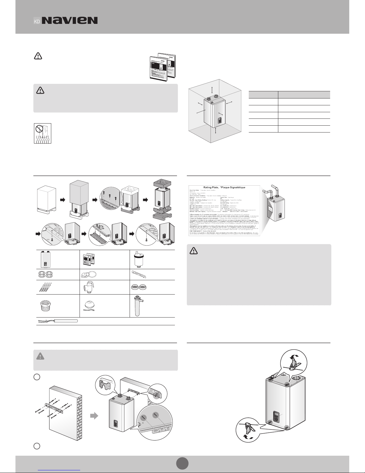
Location Requirements
Select the best location on “Choosing an Installation Location” in the Installation &
Operation Manual.
Allowable minimum clearances
Top
Back
Side
Side
Front
Bottom
Clearance Indoor Installation
Top 9 in (229 mm) minimum
Back 0.5 in (13 mm) minimum
Front 4 in (100 mm) minimum
Sides 3 in (76 mm) minimum
Bottom 12 in (300 mm) minimum
STEP 2 Installing
Checking the Rating Plate
>
This boiler is congured
for Natural Gas from the
factory. If conversion to
Propane Gas in required,
the conversion kit supplied
with the boiler must be
used.
WARNING
· Before connecting the gas supply, determine the gas type and pressure for the boiler by
referring to the rating plate. Use only the same gas type indicated on the rating plate. Using a
dierent gas type will result in abnormal combustion and malfunction of the boiler. Gas
supplies should be connected by a licensed professional only.
· The appliance and its gas connection must be leak tested before placing the appliance in
operation.
· This boiler cannot be converted from natural gas to propane or vice versa without a Navien gas
conversion kit. Do not attempt a eld conversion of this boiler without a Navien gas conversion
kit. Doing so will result in dangerous operating conditions and will void the warranty.
Navien Inc. is not liable for any property damage and/or personal injury resulting from
improper conversions.
Mounting on the Wall
>
CAUTION
Do not install the boiler on dry walls without proper reinforcement.
Drill in the supplied anchor bolts
after considering where the vent
termination will be located.
1
Lift up the boiler, rest the unit on the hooks
provided on the wall bracket on the wall.
Secure the mounting bracket to the wall
with the tapping screws and anchors.
2
Removing the Front Cover
>
Unclasp the 4 buckles that x
the cover to the boiler, and then
remove the cover by lifting it
and pulling it outward
2
3
2
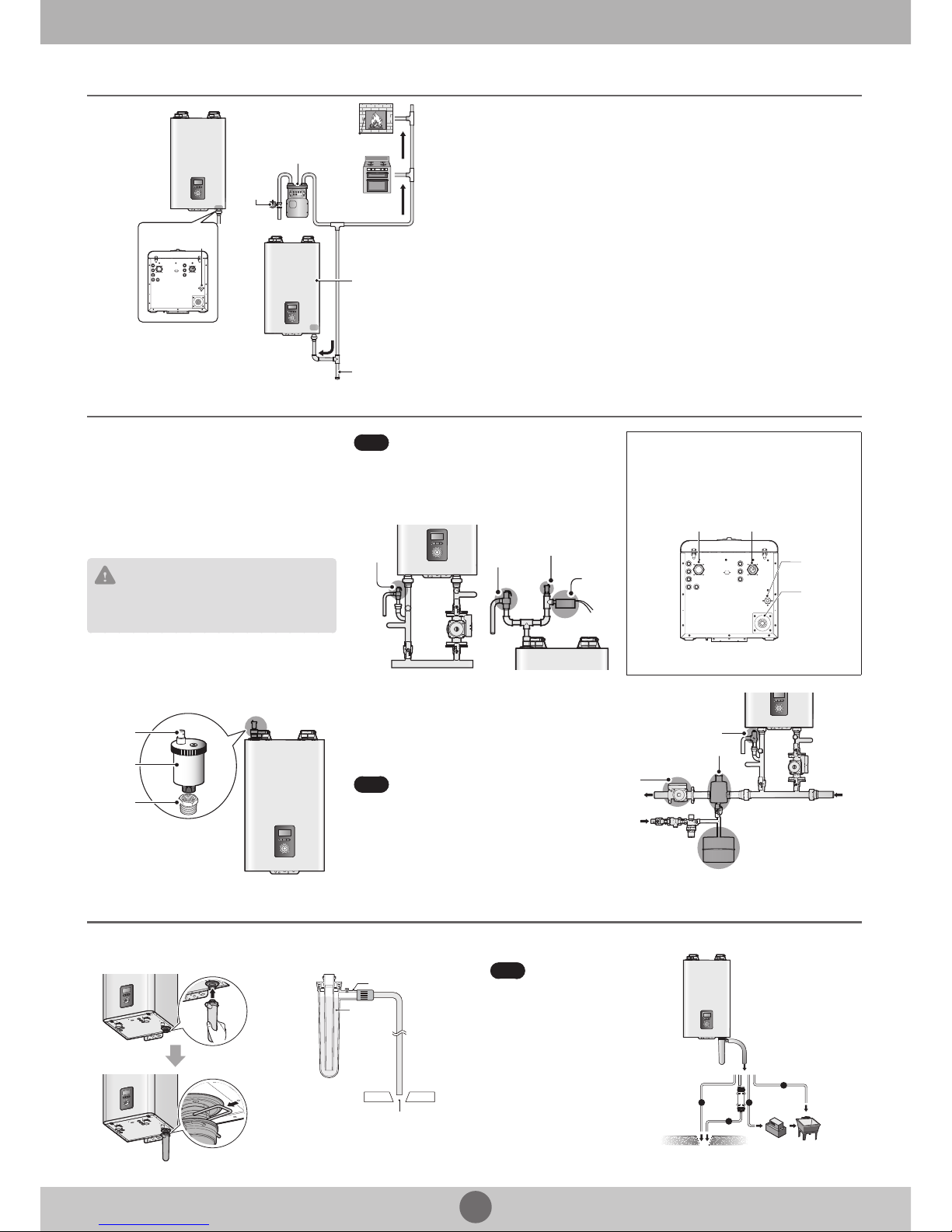
Gas Piping Connections
>
Water Piping Connections
>
Space Heating System
A pressure relief valve must be installed when installing pipings for
a heating system.
Install the included
3
/4 in, maximum 30 psi pressure relief valve on
the space heating supply.
An ASME approved HV pressure relief valve for space heating
system is supplied with the boiler.
You may install the pressure relief valve on the space heating supply
of the Navien Manifold System, or on the top connection along with
the air vent (and an external LWCO, if required).
CAUTION
Do not solder piping directly onto the water connections, as
the heat may cause damage to internal components. Use
threaded water connections only.
Note
Prior to connecting plumbing to the boiler, ush the
entire systemto ensure it is free of sediment, ux,
scale, debris or other impurities that may be harmful
to the system and boiler. During the assembly of the
heating system, it is important to keep the inside of
the piping free of any debris including construction
dust, copper burr, sand and dirt.
Pressure
Relief Valve
Pressure
Relief Valve
Air Vent
External
LWCO
Water Piping Connections
Space
Heating
Supply
Gas
Connection
Space
Heating
Return
Condensate
Outlet
System Fill Connection
Air Vent Cap
Air Vent
Air Vent
Bushing
The Navien NFB boilers have a top connection for an air vent. An air
vent must be installed to purge air from the boiler system.
When installing the air vent, install the air vent bushing between the
air vent and the top connection.
Before lling the boiler, remove the air vent cap to allow the system
to ll properly. Replace the cap when the system is full.
Note
Ensure that the vent cap is re-installed and the vent
screws on the system and boiler pumps are properly
tightened before testing or operating the system.
From
System
Expansion Tank
Make-up
Water
Pump
To system
Air Separator
Pressure Relief Valve
Gas Supply Line
Gas Inlet Adapter
Gas
Regulator
Gas supply
Bottom View
The boiler is
recommended
to be the rst
appliance to be
connected to
the gas supply
line.
Drip rig
The gas meter capacity
must be greater than
the total gas capacity of
connected appliances.
Example:
Gas meter
425 CFH
≥
Boiler
195 CFH
+
Furnace
58.8 CFH
+
Domestic gas stove
63.7CFH
* 1 CFH=1,020 Btuh
1
/2" rigid pipe can be used; refer to the sizing tables in the Installation & Operation
Manual for limitations. Avoid using 1/2" corrugated connectors or tubing as noise may
occur.
Condensate Drain Connection
>
A condensate drain pipe must be connected to the 1/2” condensate trap tting at the
bottom of the unit and water must be poured into the exhaust connection to ll the
condensate trap.
Condensate trap
Floor drain
Water
The end of the 1/2” (NPT) plastic piping should drain into a laundry tub or into a oor
drain.
Note
Do not submerge the end of
the pipe in water.
a
b
c
d
Direct to the external drain
To the
Drain via a
neutralizer
External drain
To the laundry tub
To the laundry tub
via a condensate pump
 Loading...