

Navien NCB-24LSWE, NCB-28LSWE, NCB-34LSWE, NCB-40LSWE Service Manual
Service
Manual
Service Support
Options for service support include:
●
Technical Assistance Service (TAS). A list of official TAS providers is available at
http://www.navienuk.com. Contact a TAS for all warranty claims.
●
The technician or company that installed your boiler.
●
A registered service provider.
When you contact a TAS, please have the following information available.
●
Model
number
●
Serial
number
●
Date of
●
Installation location and
●
Error code information from the front display panel if available
purchase
Condensing Combi Boiler
type
KD Navien Co.,Ltd
Version: 1.0 (Oct. 19. 2015)
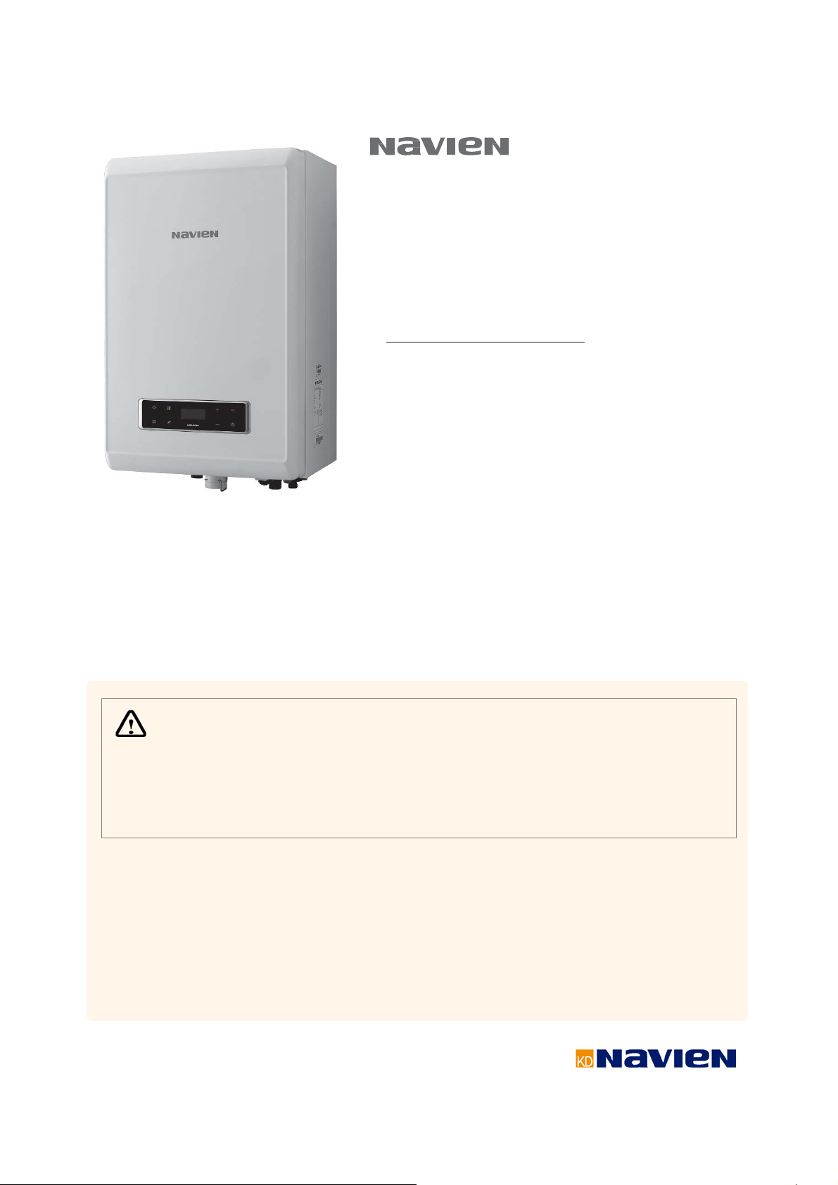
Condensing Combi Boiler
Service
Manual
Model
NCB-24LSWE
NCB-28LSWE
NCB-34LSWE
NCB-40LSWE
Keep this manual near the boiler for future reference.
WARNING
The safety information contained in this manual is important. Not following the
safety precautions may cause a fire or explosion and result in property damage,
injury, or death.
-
Do not store or use gasoline or other flammable liquid or vapour near this or any other appliance.
-
WHAT TO DO IF YOU SMELL GAS
●
Do not use any appliances.
●
Do not turn on any electrical devices or circuits. Do not use a phone inside the building.
●
Call your gas supplier from a phone outside the building. Follow the gas supplier’s instructions.
●
If you cannot reach your gas supplier, call the fire service.
-
Installation and service must be performed by a qualified installer, service agency or the gas supplier.

Revisions
Version Description of changes Date
1.00 First issue Mar. 12, 2015
Version 1.0
NCB Service Manual 1

Contents
1. Safety Information 5
1.1 Safety Definitions 5
1.2 Safety Symbols 5
1.3 Instructional Symbols 5
1.4 Safety Precautions 5
2. Product Information 12
2.1 Product Information 12
2.2 Components 13
3. Technical Data 17
3.1 General Specifications 17
3.2 Dimensions 19
4. System Details 20
4.1 Setting the DIP Switches 20
4.1.1 PCB DIP Switches 20
4.1.2 Front Panel DIP Switches 21
4.2 Measuring the Incoming Gas Pressure 21
4.3 Gas Conversion 23
4.4 The Front Panel 30
4.4.1 LCD Display 30
4.4.2 Buttons 31
4.4.3 Turning the Boiler ON or OFF 33
4.4.4 Normal Operation 33
4.4.5 Displaying and resetting errors 35
4.4.6 Adjusting the Space Heating Temperature set point 35
4.4.7 Adjusting the DHW Temperature 36
4.4.8 Viewing Basic Information 37
4.4.9 Displaying Error History 39
4.4.10 Displaying Service Information 40
4.4.11 Service Status Information 43
4.4.12 Parameter Setting Mode 45
4.4.13 Resetting The Boiler (Factory Reset) 56
4.5 Version Display 57
4.6 Heat Demand 57
4.7 Error Codes 57
4.8 Electrical Diagnostic Contacts and Wiring Diagram 58
4.9 Key Component Descriptions 60
4.9.1 PCB 60
4.9.2 High Temperature Limit Switch 61
4.9.3 Thermistor 62
4.9.4 Fan Motor 63
4.9.5 Flame Rod Assembly 64
4.9.6 Ignition Transformer 65
4.9.7 APS 66
4.9.8 Main Gas Valve 67
4.9.9 Burner (to be revised) 68
4.9.10 Flow Sensor (to be revised) 69
4.9.11 Primary Heat Exchanger 70
4.9.12 Secondary Heat Exchanger 71
4.9.13 DHW Heat Exchanger 72
4.9.14 Circulation Pump 73
4.9.15 3 Way Valve 74
4.9.16 Water Pressure Sensor 75
4.9.17 Dual venturi 76
4.9.18 Expansion tank 77
5.2.2 Error 003 84
5.2.3 Error 004 90
5.2.4 Error 012 91
5.2.5 Error 016 94
5.2.6 Error 030 96
5.2.7 Error 046 98
5.2.8 Error 047 98
5.2.9 Error 060 99
5.2.10 Error 109 101
5.2.11 Error 110 103
5.2.12 Error 205 104
5.2.13 Error 218 106
5.2.14 Error 302 108
5.2.15 Error 352 109
5.2.16 Error 353 110
5.2.17 Error 407 111
5.2.18 421Error 113
5.2.19 515Error 115
5.2.20 517Error 116
5.2.21 594Error 116
5.2.22 615Error 116
5.2.23 740Error 117
5.2.24 782Error 118
5.3 Troubleshooting guide by symptom 119
5.3.1 Noise 119
5.3.2 Water Temperature Issue 120
5.3.3 Circuit breaker operation 121
6. Replacement of Parts 122
6.1 Replacement Procedure 122
6.2 Components Replacement Instructions 123
6.2.1 PCB 123
6.2.2 Fuse 123
6.2.3 Fan Motor (Combustion Air) 123
6.2.4 Flame Rod 124
6.2.5 Ignition Transformer 125
6.2.6 APS 126
6.2.7 Main Gas Valve 126
6.2.8 Condensate Trap 127
6.2.9 Circulation Pump 128
6.2.10 Flow Sensor 128
6.2.11 3-way Valve 129
6.2.12 Water Pressure Sensor 129
6.2.13 DHW Heat exchanger 130
6.2.14 Expansion tank 130
7. Components Diagram and Part List
7.1 Case Assembly 131
7.2 Burner Assembly 132
7.3 H-Ex Assembly 133
7.4 Waterway Assembly 134
7.5 Gas Assembly 135
7.6 Fan Assembly 136
8. Inspection and Maintenance Schedule 137
8.1 Annual Servicing 137
8.2 Maintenance Report 137
8.3 Maintenance Schedules 137
8.4 Inspection Report 137
131
5. Troubleshooting 78
5.1 Error Code Classification 78
5.2 Error Code List and Actions 79
5.2.1 Error 001 82
2 NCB Service Manual
Version 1.0
Navien Warranty
Warranty Period
Navien products come with a limited warranty covering. The
warranty covers labour, parts, and the heat exchanger. The
warranty period starts from the date of original installation.
The date of original installation must be advised to Navien,
and if requested, proof of the original installation date must
also be provided to Navien. When the product is installed in
a new installation, the warranty period will start from the
date the end-user takes responsibility for the property.
Product Warranty Period
NCB Series Boiler
(Residential use, single dwelling)
Warranty Claim Procedure
To obtain warranty repair service, the end user or
homeowner must contact the original installer of the Navien
product. If the original installer is unknown, the end user or
homeowner can contact the Navien Technical Department
at
0844–332-2323
warranty service.
. Proof of purchase is required to obtain
Warranty Service
At its option, Navien will replace the defective component
(part(s) or heat exchanger), in accordance with the terms of
this Limited Warranty, if it fails in normal use and service
during the Applicable Warranty Period identified above. The
replacement component must be Navien original factory
component. Navien, at its sole discretion, may replace the
product with a new or refurbished product of comparable
quality and design. The replacement component or product
will be warranted only for the unexpired portion of the
original component’s Applicable Warranty Period. Payment
for labour in completing the warranty service is subject to
Navien’s prior written approval and shall be subject to
Navien’s schedule of approved labour allowances.
Warranty Exclusions
Navien’s Limited Warranty shall be void in the event of an
occurrence of any of the following:
Improper installation, failure to install in strict compliance
with the Installation Manual procedures, installed by a
non-licensed installer, and installation in violation of
applicable rules, laws or building codes.
Product purchased through the internet, other ecommerce channels, or any installer that obtained the
Product from a supplier or distributor not authorised by
Navien.
3 years
Failure to perform regular maintenance, misuse,
operation at settings other than those recommended or
specified, non-compliance with instructions or guidelines
set forth in the User’s Operation Manual.
Modification or alteration of the Product in any manner,
including but not limited to, removal of any component
or part, addition of any non-approved components,
relocating or moving the Product from its original
installation site, or any accidental or intentional damage
to the Product.
Installation in commercial or multi-unit dwelling
applications or for non-recommended uses.
Any damage caused by local adverse conditions including
but not limited to hard water deposits, lime or mineral
build-up, operating in corrosive atmospheric elements.
Damage or caused by gas flow issues, electrical surges,
flooding, fire, abnormal external temperature, and any
other cause of damage not directly caused by a
manufacturing defect.
Installer’s failure to fully comply with the Warranty Service
and Return Policy procedures previously provided to
Installer and as is available on Navien’s website. Such
policies include but are not limited to the Installer’s failure
to first contact Navien Technical Support while in front of
the product for purposes of trouble shooting the
identified problem or issue.
Performance problems caused by improper sizing of the
boiler, the gas supply line, the flue connection,
combustion air openings, electric service voltage, wiring,
fusing or any other components, parts or specifications.
Improper conversion from natural gas to LP gas or LP gas
to natural gas or attempt to operate with a type of gas
not specified for the boiler.
Any damage, malfunction or failure caused by abuse,
negligence, alteration, accident, fire, flood, freezing, wind,
lightning and other acts of God.
Operating, using or storing the boiler in a corrosive or
contaminated atmosphere or environment.
Operating the boiler at water temperatures outside the
factory calibrated temperature limits and/or exceeding
the maximum setting of the high limit control.
Operating the boiler when it is not supplied with potable
water at all times.
Subjecting the heat exchanger to pressures or firing rates
greater or lesser than those shown on the rating plate.
Removal or alteration of the rating plate.
Version 1.0
NCB Service Manual 3
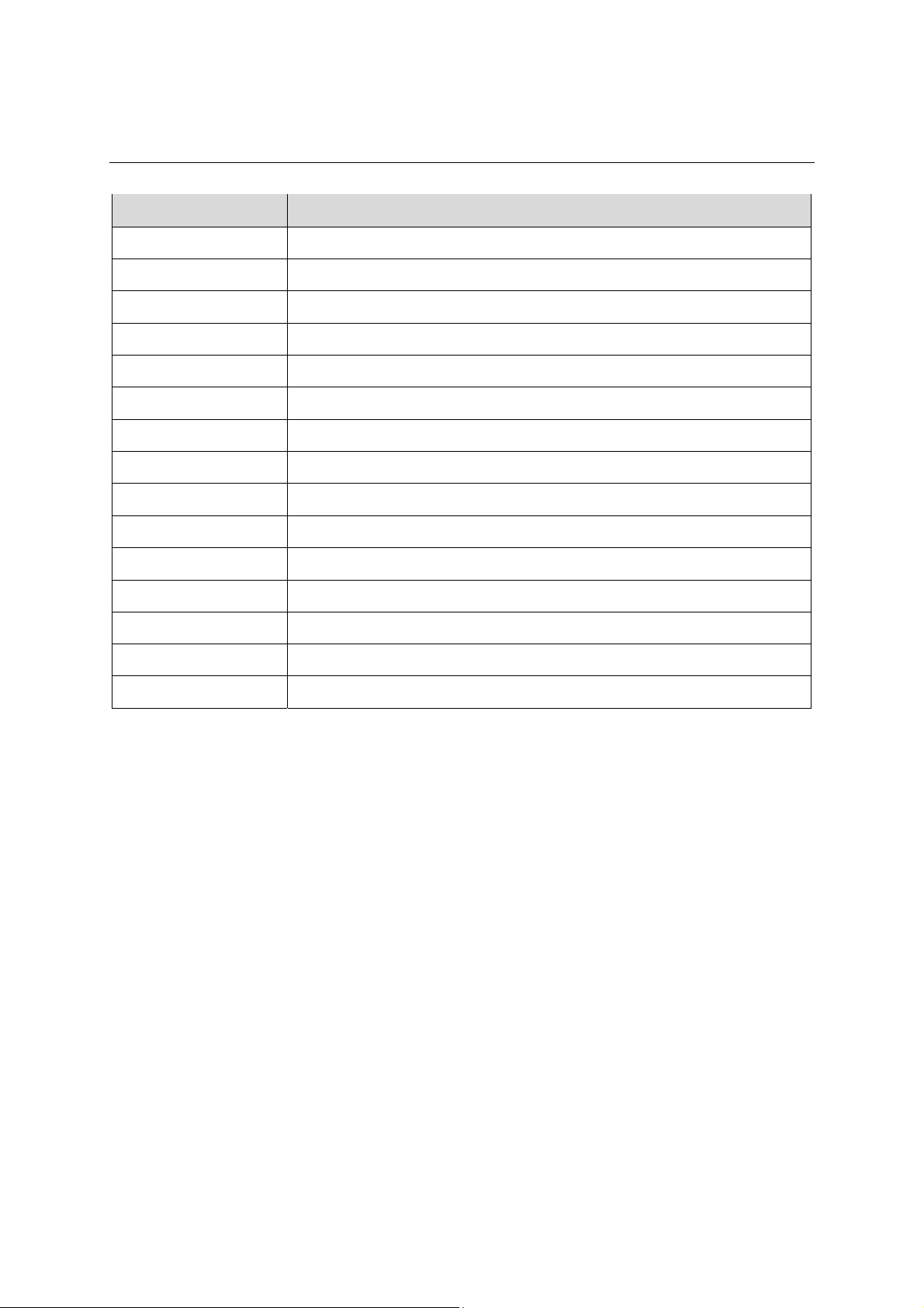
Abbreviations and Definitions
Abbreviation Definition
NCB-CE General name for NCB-24LSWE, NCB-28LSWE, NCB-34LSWE, and NCB-40LSWE products
NG Natural Gas
LP Propane Gas
AP Air Pressure
APS Air Pressure Sensor
DHW Domestic Hot Water
FM Fan Motor
GARC Gas Air Ratio Control
LPM Litre Per Minute
MGV Main Gas Valve
RPM Revolutions per Minute
PCB Printed Circuit Board
EMI Electromagnetic Interference
HTL High Temperature Limiter
LWCO Low Water Cut Off
4 NCB Service Manual
Version 1.0
1. Safety Information
1.1 Safety Definitions
The following safety symbols are used in this manual. Read
and follow all safety instructions in this manual to avoid
unsafe operating conditions, fire, explosion, property
damage, personal injury, or death.
1.2 Safety Symbols
DANGER
Indicates an imminently hazardous
situation which, if not avoided, could
result in severe injury or death.
WARNING
Indicates a potential hazardous
situation which, if not avoided, could
result in injury or death.
CAUTION
Indicates an imminent hazardous
situation which, if not avoided, may
result in minor or moderate injury.
1.3 Instructional Symbols
IMPORTANT
Warns of a risk of damage and
environmental pollution.
NOTE
Indicates additional information that
is important but not related to
personal injury or property damage.
1.4 Safety Precautions
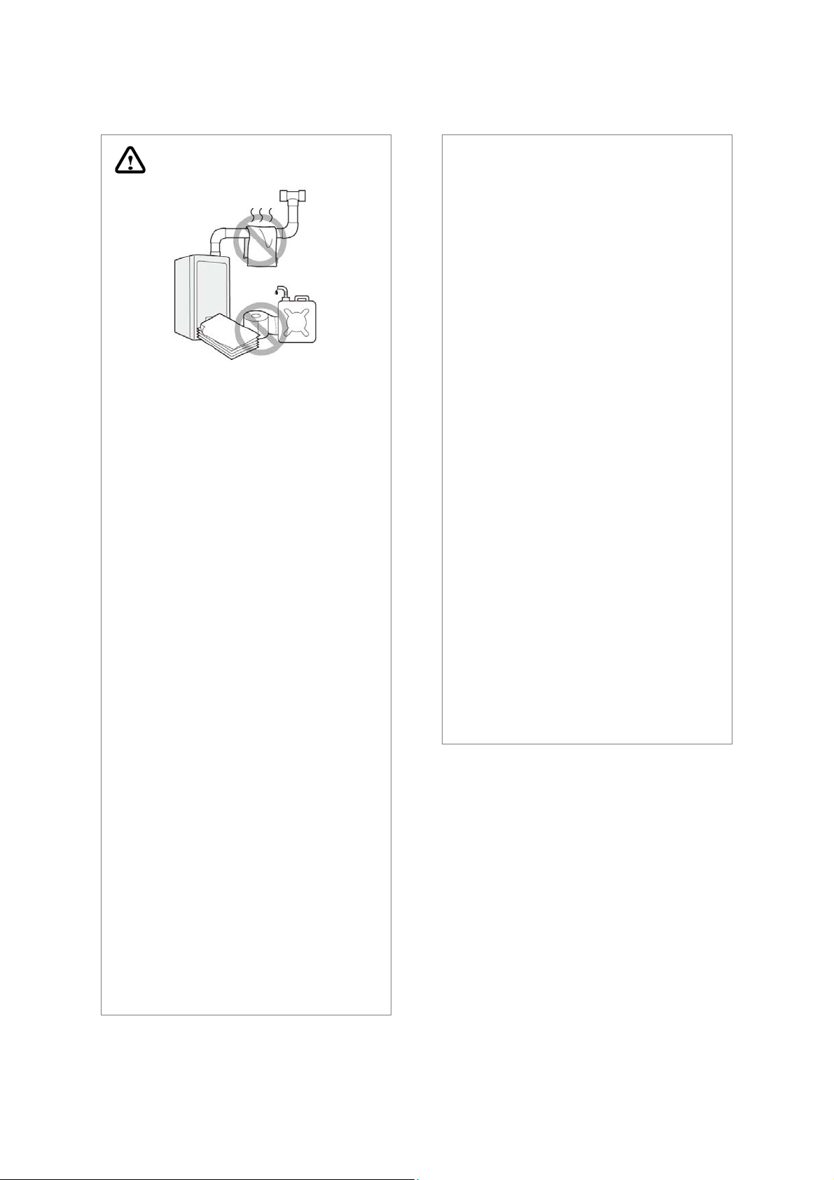
DANGER
FLAMMABLE MATERIALS
Keep the area around the boiler clear
and free from flammable materials.
DO NOT place flammable liquids
such as oil or gasoline, near the
boiler.
DO NOT place combustibles such
as newspapers and laundry, near
the boiler or the flue system.
Version 1.0
DO NOT place or use hair spray or
paint aerosols or any other type of
aerosol can near the boiler or the
flue system (including the flue
termination).
DO NOT place anything in or
around the flue terminations that
could obstruct the air flow in and
out of the boiler, such as a clothes
line.
NCB Service Manual 5
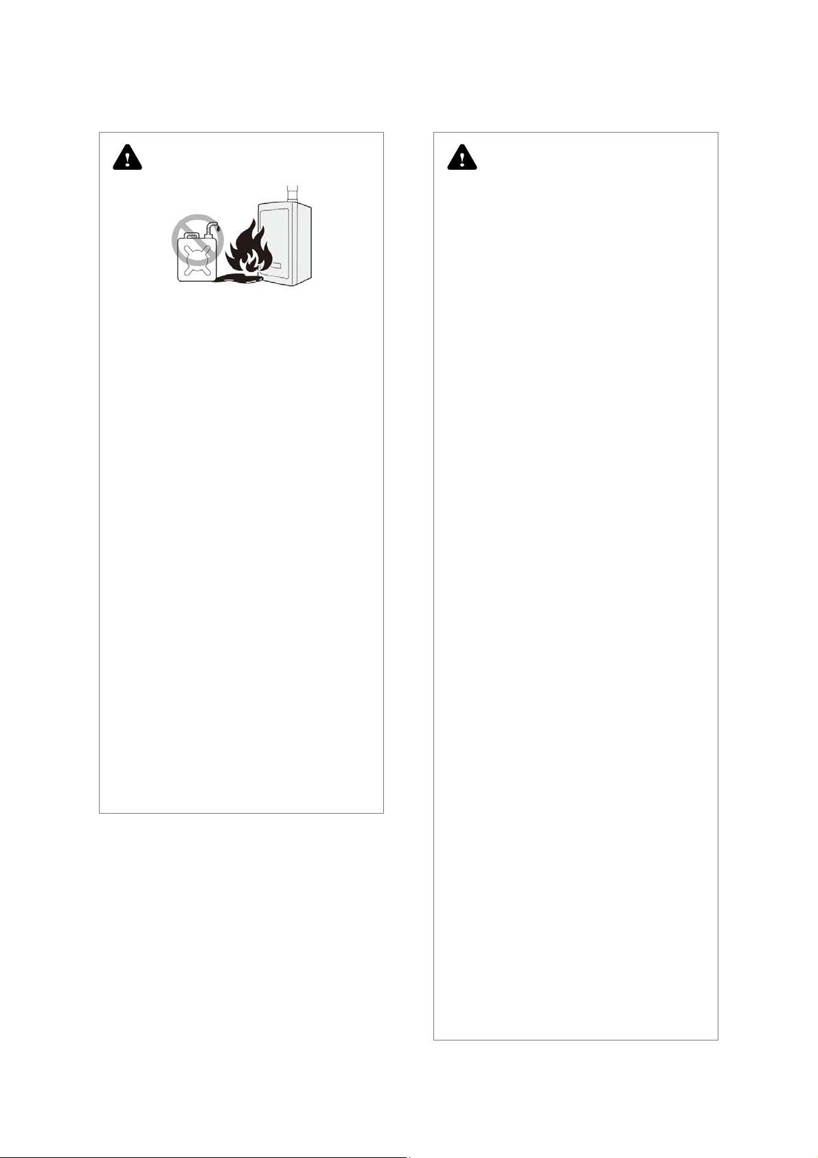
DANGER
FLAMMABLE VAPOUR
Vapours from flammable liquids can
explode and cause fire resulting in
death or severe burns.
Do not use or store flammable
products such as gasoline, solvents,
or adhesives in the same room or
area near the boiler.
Store flammable products far away
from the boiler in approved
containers, with the lid tightly
closed, and out of the reach of
children.
The boiler’s main burner ignites
automatically at various intervals
and may ignite flammable vapours.
Flammable vapour is invisible, is
heavier than air, and can travel
long distances at floor level.
Dangerous concentrations of
flammable vapour can be moved
by air flow from other rooms
towards the main burner flame.
DANGER
WHAT TO DO IF YOU SMELL GAS
It is important that these instructions
are followed exactly to avoid fire or
explosion, property damage,
personal injury, or loss of life.
DO NOT OPERATE THE BOILER.
DO NOT CREATE ANY SOURCES OF
IGNITION
DO NOT OPERATE ANY FAUCETS.
Smell around the appliance area for
gas. Ensure to smell close to the floor
because gas is heavier than air and
will settle on the floor.
Do not smoke.
Extinguish all open flames.
Do not use appliances of devices
that generate sparks.
Do not operate light switches or
use electrical equipment.
Do not use a phone inside the
building.
Open the windows and doors.
Keep people away from the danger
zone.
Close the gas shutoff valve.
Observe the gas supplier’s safety
instructions posted on the gas
meter.
As soon as possible call the gas
supplier from outside of the
building. Follow the gas supplier’s
instructions.
If you cannot contact your gas
supplier, call the emergency
services. Notify your plumbing or
heating contractor when you are
outside of the building.
6 NCB Service Manual
Version 1.0
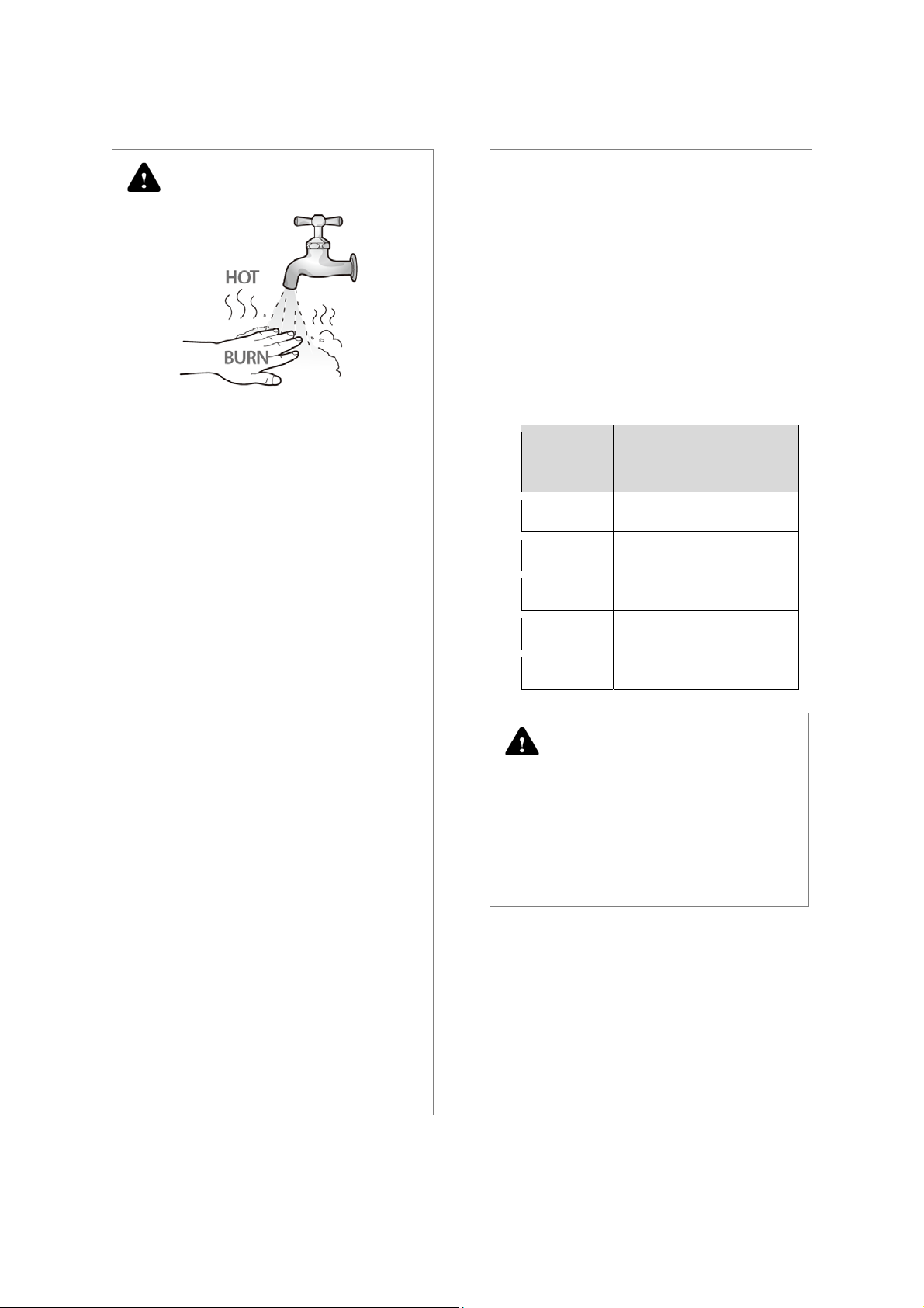
DANGER
HOT WATER TEMPERATURE
SETTING
Water temperatures at or above
52°C can cause instant severe
burns or scalding that can result in
serious injury or death.
Households with small children, or
disabled or elderly people, may
require a temperature setting of
49°C or lower for a safer water
temperature.
TO PREVENT BURNS
For your safety and comfort, the
default water temperature setting
is 49°C. Increasing the temperature
increases the risk of accidental
burns or scalds. Water temperature
at or above 52°C can cause instant
scalding, severe burns, or death.
Before you change the
temperature setting, read the
following table carefully.
Water
Temperature
70 ℃
60 ℃
55 ℃
49 ℃
37 ℃
Time for a young child to
receive full thickness (third
degree) burns
Less than 1 second
1 second
10 second
10 minutes
Very low risk of scalding
Use the lowest operating
temperature setting that provides
a comfortable water temperature.
If the household has children, or
elderly or disabled residents, use a
lower temperature setting.
Read all instructions in this manual
carefully before changing the
temperature setting.
Check the water temperature
before allowing children, or elderly
or disabled people to use it.
Contact a registered plumber or
your local plumbing authority for
more information.
DANGER
INSTALLATION REQUIREMENTS
Installation method may affect
how the boiler is serviced. Read all
related information in the
“Installation Manual”.
Version 1.0
NCB Service Manual 7
DANGER
IMPORTANT SAFETY PREAUTIONS
Read the safety information before
operating or servicing Navien
boilers.
Confirm the location of the gas
shut-off valve. During servicing,
close the manual shut-off valve if
the boiler overheats or is subjected
to fire, flood, physical damage or
other similar conditions.
DO NOT turn on the boiler unless
the water and gas supplies are
connected and supplied.
DO NOT turn on the boiler if the
main water supply valve is closed.
Ensure the boiler’s power supply is
isolated before removing the front
cover.
WARNING
GAS TYPE and POWER SUPPLY
This default gas supply
configuration for this boiler is
Natural Gas. If it is converted to
Propane Gas, the conversion kit
supplied with the boiler must be
used.
The power supply must be 230
VAC, 50 Hz. Voltages that are
abnormally high or low may affect
operation and reduce the life of the
boiler.
If the gas or power supplies do not
match the specifications do not
connect the boiler. Contact Navien
for assistance.
Label all wires prior to
disconnection. Wiring errors can
cause improper and dangerous
operation. Test and verify that the
boiler operates safely and correctly
after it is serviced or repaired.
Incorrect adjustments,
modifications, servicing or
maintenance can cause property
damage, personal injury, or death.
To prevent scalding, always check
the hot water temperature when
servicing is completed.
DO NOT change the water
temperature while the boiler is in
use.
DO NOT use parts other than those
specified for the boiler.
DO NOT allow children to operate
or handle the unit.
8 NCB Service Manual
Version 1.0
WARNING
Isolate the gas supply if the
boiler is damaged.
Identify the location of the gas
shut off valve and ask a qualified
technician to demonstrate how to
close the valve. If the boiler is
damaged due to overheating, fire,
flood, or any other reason, close
the shut off valve and do not
operate the boiler until it has been
inspected by a qualified
technician.
DO NOT store or use gasoline or
other flammable liquids near the
boiler.
Doing so may result in fire or
explosion.
DO NOT place combustibles,
such as newspapers or laundry,
near the boiler or flue system.
Doing so may result in a fire.
DO NOT operate the boiler with
an open front cover.
Doing so may result in fire or
carbon monoxide (CO) poisoning
and may result in property
damage, personal injury, or death.
DO NOT operate this boiler
without proper flue system.
Doing so may result in fire or
carbon monoxide (CO) poisoning
and may result in property
damage, personal injury, or death.
Inspect the flue termination and
air intake supply at least annually
to ensure proper operation of the
boiler. Turn off and discontinue
using the boiler if any of the flue
pipes, flue elbows, or intake pipes
are damaged, have loose
connections, or has signs of
corrosion or heat damage.
DO NOT touch the power cord or
internal components of the
boiler with wet hands.
Doing so may result in electric
shock.
DO NOT place or use hair spray
or paint aerosols, or any other
compressed gases near the
boiler or flue system, including
the flue termination.
Doing so may result in fire or
explosion.
Version 1.0
NCB Service Manual 9

CAUTION
Do not attempt to repair or
replace any part of the boiler
unless it is specifically
recommended in this manual.
For repairs not covered in this
manual, contact a qualified
technician or a licensed
professional. Incorrect
adjustments, modifications,
servicing, or maintenance may
cause property damage, personal
injury, or death and will void the
warranty.
Do not allow children to operate
or access the boiler.
Doing so may result in property
damage or personal injury.
Do not change the water
temperature while the boiler is
being used.
Doing so may result in personal
injury.
DO NOT turn on the boiler unless
the water and gas supplies are
connected and supplied Doing
so may damage the boiler.
DO NOT use hot water inside the
installation when the main water
supply shut-off valve is closed.
Doing so may damage the boiler.
DO NOT use the boiler for
purposes other than those
described in this manual.
DO NOT remove the front cover
unless the power to the boiler is
turned off or disconnected.
Failure to do so may result in
electric shock.
When servicing the control
circuits, label all wires prior to
disconnecting them.
Failure to do so may result in
wiring errors and lead to improper
or dangerous operation.
Do not use unauthorised
replacement parts or
accessories.
Doing so may result in improper or
dangerous operation and will void
the manufacturer’s warranty.
Do not place anything in or
around the flue terminals, such
as a clothes line, that can
obstruct the air flow in or out of
the boiler.
If the boiler overheats or the gas
supply fails to shut off, isolate
the gas at the boiler’s main
valve.
Do not use this appliance if any
part has been covered by water.
Contact a qualified service
technician to inspect the appliance
to verify the boiler is safe to
operate and to replace any
damaged parts.
10 NCB Service Manual
Version 1.0
General Installation
Navien guarantees that no
have been used
All current and local laws and regulations must
the boiler. The boiler must
when
adequately
The boiler must
ventilated area.
Guidelines
harmful
substances or materials
in the manufacture of this product.
be
be
installed
installed
by registered installers
in
an
be observed
.
Commissioning of the boiler must be performed by a
Navien authorised TAS
The requirements included
be
observed
must
-
Gas installation r
-
Technical building c
- Building h
eating installation regulations
.
on
installing the
egulations.
odes.
in
the following regulations
boiler:
.
- Elec tric a l regulations.
The latest version of the regulations and codes
of
practice must be applied to the installation methods
The installation must also comply with the
European
Standards listed in the table below:
Standard Description
UNE-EN
13831:2008
Closed expansion vessels with
diaphragm.
UNE-EN 1856 Metal chimneys
EC
Conformity
Declaration
Navien, hereby declares that the boiler
NCB-24LSWE, NCB-28LSWE, NCB-34LSWE,
which this declaration refers, conform
to
with
the essential requirements
models:
NCB-40LSWE
to
and comply
of
the following applicable
European
Standards and
Gas appliances
Directives.
: Directive 2009/142/EC Standards
EN
437
and EN 15502
Boiler Efficiency
: Directives 92/42/EEC
93/68/EEC Standards
Low voltage
.
Electro-magnetic Compatibility
Pressure Vessels
Navien, manufactures
Assurance
: Directives 73/23/EEC
Standard
EN
system
EN
60335-1,
60335-2-51,
: Directive
in
97/23/EEC
its
products using a Quality
compliance with Standard EN-ISO
EN 50165
and
EN 15502
and
93/68/EEC
EN 60335-2-30,
: Directive
2004/108/EC
Standards
EN 55014
9001:2000.
UNE-EN 13384 Chimneys
UNE-EN 13779 Ventilation
UNE-EN ISO 16484 Building control systems.
UNE-EN 14336 Heating systems in buildings.
UNE-EN 15502-1
Gas-fired heating boilers
Part 1: General Requirements and
Gas-fired heating boilers
Part 2-1: Specific standard for type C
UNE-EN 15502-2-1
appliances and type B2, B3 and B5
appliances of a nominal heat input
not exceeding 1000kW
UNE-EN
13203:2007
UNE-EN 3037:2008
Domestic Hot Water
Heating boilers.
Version 1.0
NCB Service Manual 11
2. Product Information
2.1 Product Information
The NCB series gas boiler is a fully modulating gas appliance which has a built-in circulation pump and air vent. It provides central
heating and domestic hot water. Depending on the heat capacity, three models are available with different ratings: 24 kW, 28 kW,
34kW, and 40 kW.
Model Maximum Space Heating Input Maximum DHW INPUT
NCB-24LSWE 20.0 kW 24.0 kW
NCB-28LSWE 24.0 kW 28.0 kW
NCB-34LSWE 29.0 kW 34.0 kW
NCB-40LSWE 34.0 kW 40.0 kW
By default, the boiler assigns system priority to DHW supply.
The NCB Series boiler has a built-in circulation pump, 3-way valve assembly, flow sensor, DHW plate heat exchanger and, a
safety valve (or relief valve). A separate heating expansion vessel is required.
Internal freeze protection and an electronic control unit are incorporated inside the boiler. The boiler is compatible with all
brands of standalone room thermostats and various sets of relay contacts can be used with the boiler.
12 NCB Service Manual
Version 1.0
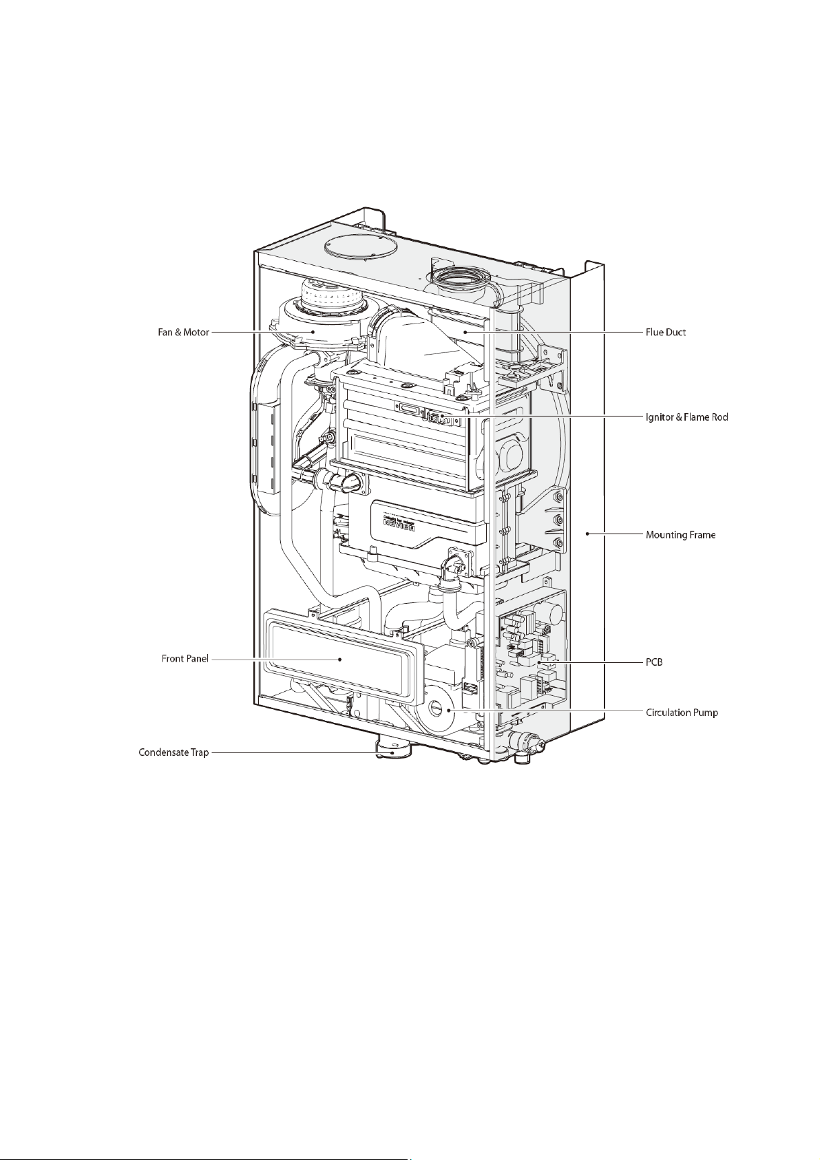
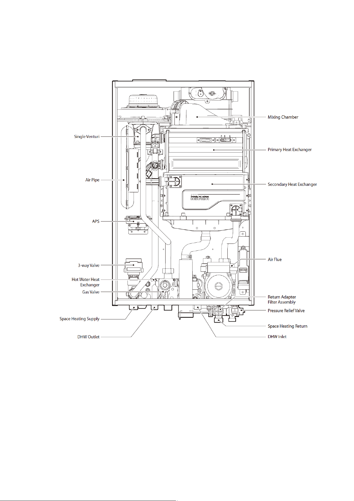
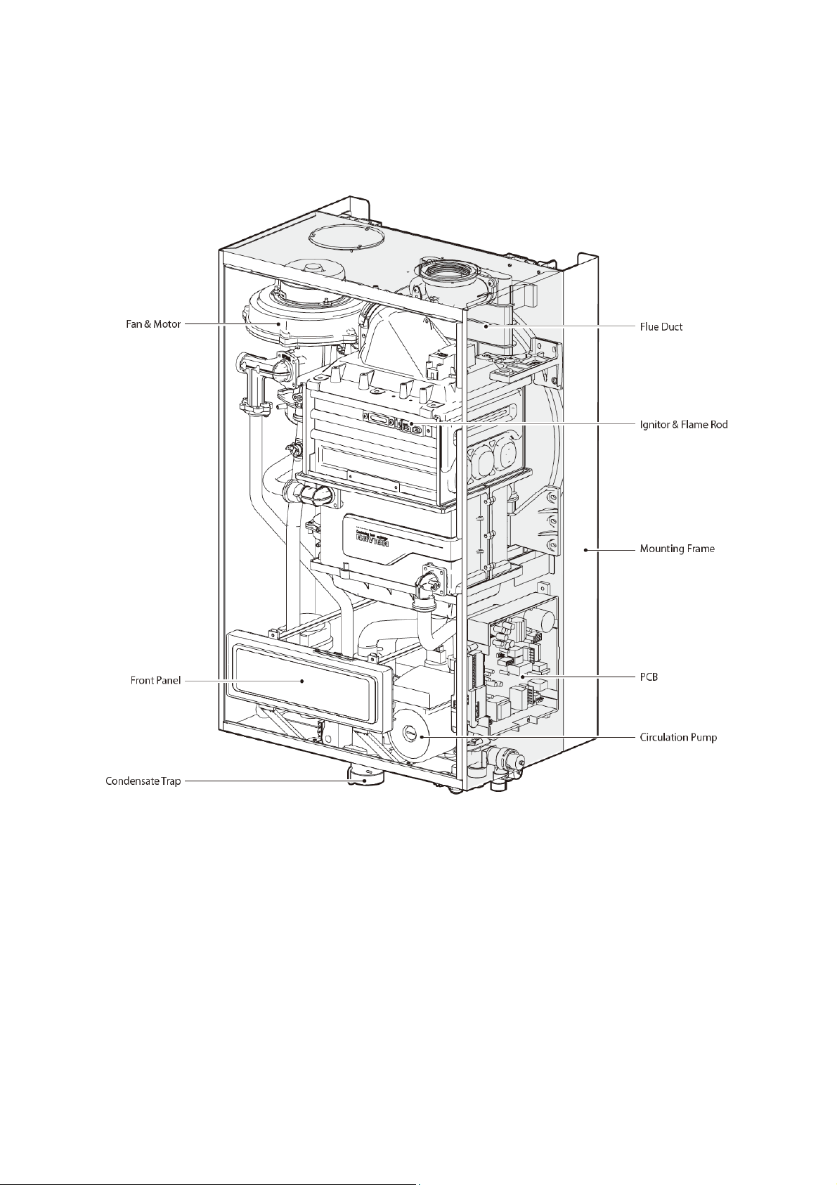
2.2 Components
The following diagram shows the key components of the boiler. Component assembly diagrams and particular parts lists are
included in the appendices.
NCB-24/28/34LSWE
Version 1.0
NCB Service Manual 13
NCB-24/28/34LSWE
14 NCB Service Manual
Version 1.0
NCB-40LSWE
Version 1.0
NCB Service Manual 15
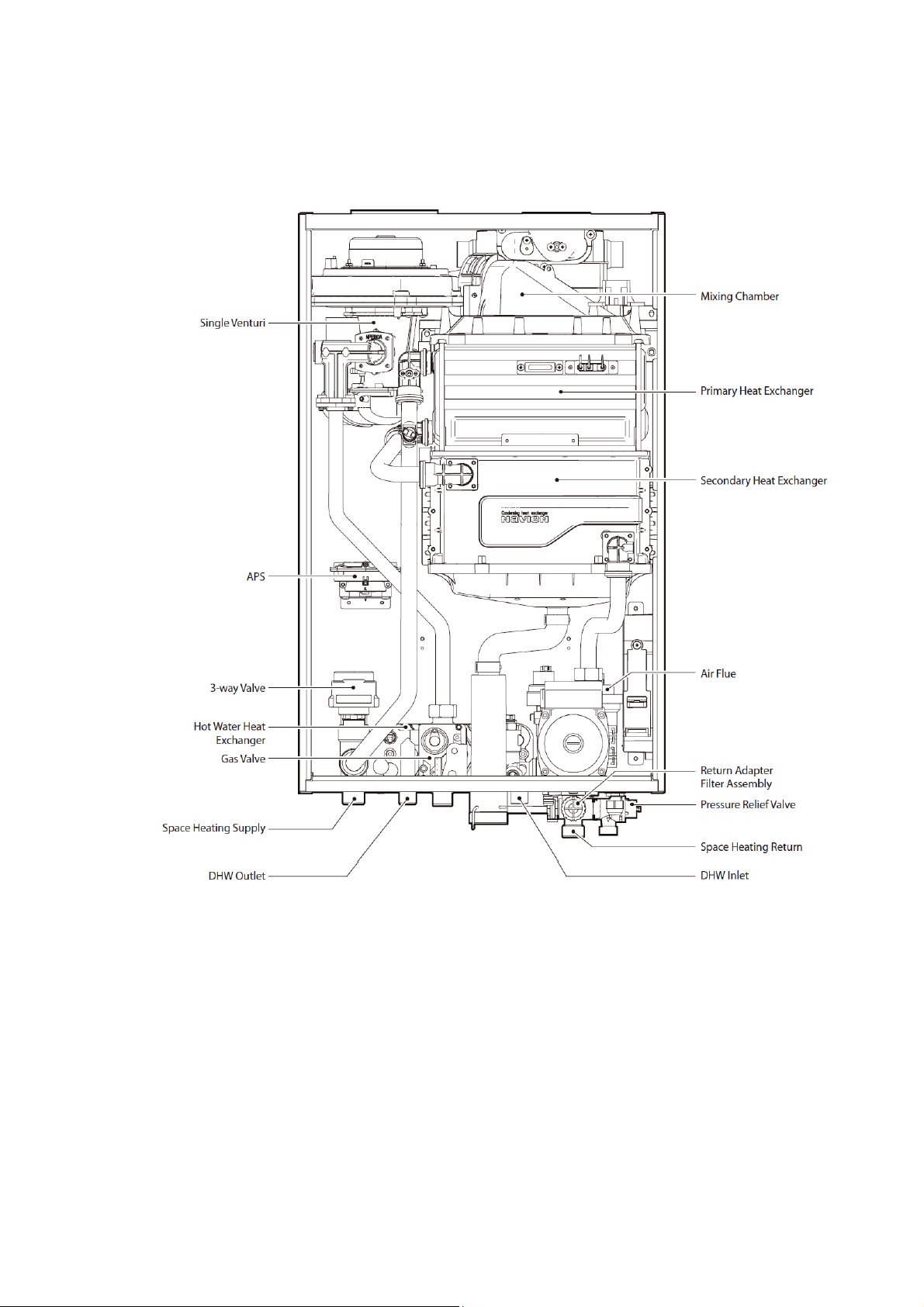
NCB-40LSWE
16 NCB Service Manual
Version 1.0
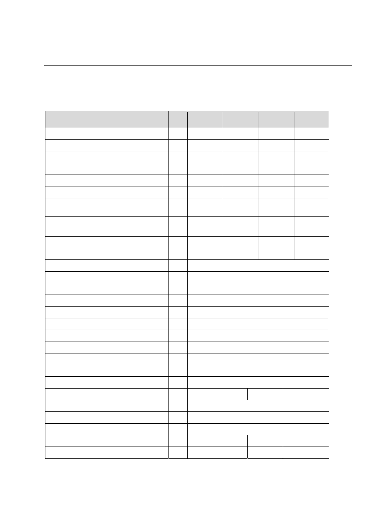
3. Technical Data
3.1 General Specifications
The table below lists the boiler’s general specifications.
Specification Unit
Heating capacity (max/min)
NCB-
24LSWE
kW 20.0/4.2 24.0/4.2 29.0/5.1 34.0/4.0
NCB-
28LSWE
NCB-
34LSWE
NCB-
40LSWE
DHW heat capacity (max/min)
Heating output (max/min) at 80/60°C
DHW output (max/min)
Condensing heating output (max/min) at 50/30°C
Full output load efficiency (max/min), at 80/60°C
Full output load efficiency (max/min), at 50/30°C
(condensation)
Partial load (30%) efficiency, at 30°C return
temperature
Heat Loss via the casing with burner switched on
Heat Loss via the chimney with burner switched on
Seasonal efficiency rate (SEDBUK rating)
NOx class
Category
Type
Heating output adjustment
Type of heating installation
kW 24.0/4.2 28.0/4.2 34.0/5.1 40.0/4.0
kW 19.5/4.0 23.3/4.2 28.4/4.9 33.2/3.8
kW 20.0/4.0 24.0/4.0 34.0/5.0 40.0/4.0
kW 21.4/4.5 25.5/4.5 31.1/5.5 36.2/4.3
% 97.7/96.4 97.2/96.4 97.9/96.4 97.5/95.8
% 106.9/107.8 106.3/107.8 107.3/107.9 106.6/107.9
% 108.3 108.3 108.6 108.8
% 0.1 0.1 0.1 0.1
% 1.6 1.8 1.5 1.9
- A
- 5
- II2H3P
- Heating and instantaneous hot water production
- Adjustable over entire max/min output range
- Closed circuit
Maximum heating pressure
Maximum heating temperature
Adjustable heating temperature range
Expansion vessel volume
Expansion vessel pre-load
Minimum DHW pressure
Minimum DHW flow
Maximum DHW pressure
Adjustable DHW temperature range
Specific flow (T=25°C)
Specific flow (T=30°C)
Version 1.0
bar 2.5
°C 90
°C 40-90
l 6. 0
bar 1
bar 1.0 1.2 1.4 1.4
l/min 2.0
bar 10
°C 30–65
l/min 13.8 16.1 19.5 22.9
l/min 11.5 13.4 16.2 19.1
NCB Service Manual 17
Specification Unit
Specific flow for kitchens (T=45°C)
NCB-
24LSWE
NCB-
28LSWE
NCB-
34LSWE
NCB-
40LSWE
l/min 7.6 8.9 10.8 12.7
Electrical supply
Nominal current
Electrical maximum rating
Electrical protection
Boiler mounting method
Flue exhaust/Air intake system types
Flue exhaust/Air intake system diameters
Max. horizontal coaxial pipe length Ø60/100
Max. vertical coaxial pipe length Ø60/100
Equivalent elbow length at 90° Ø60/100
Equivalent elbow length at 45° Ø60/100
Max. horizontal coaxial pipe length Ø80/125
Max. vertical coaxial pipe length Ø80/125
Equivalent elbow length at 90° Ø80/125
Equivalent elbow length at 45° Ø80/125
Equivalent length of adapter Ø60/100 => Ø80/125
- 230 V / 50 Hz
A 0.6 0.62
W 130
- IP X5D
- Wall-mounted
- B23-B33-B53-C13-C33-C43-C53-C63-C83
mm Coaxial Ø60/100 and Ø80/125–Dual duct Ø80/80
m 20
m 21
m 1.3
m 1
m 68
m 70
m 2.2
m 1
m 0.5
Max. dual duct length Ø80-Ø80
Equivalent elbow length at 90° Ø80
Equivalent elbow length at 45° Ø80
m 110
m 2.2
m 1.4
Heating mm 22
Hydraulic connection diameter
DHW mm 15
Gas inlet mm 22
Dimensions (width x depth x height)
Weight
mm 440 x 350 x 695 440 x 380 x 695
kg 38 42
18 NCB Service Manual
Version 1.0
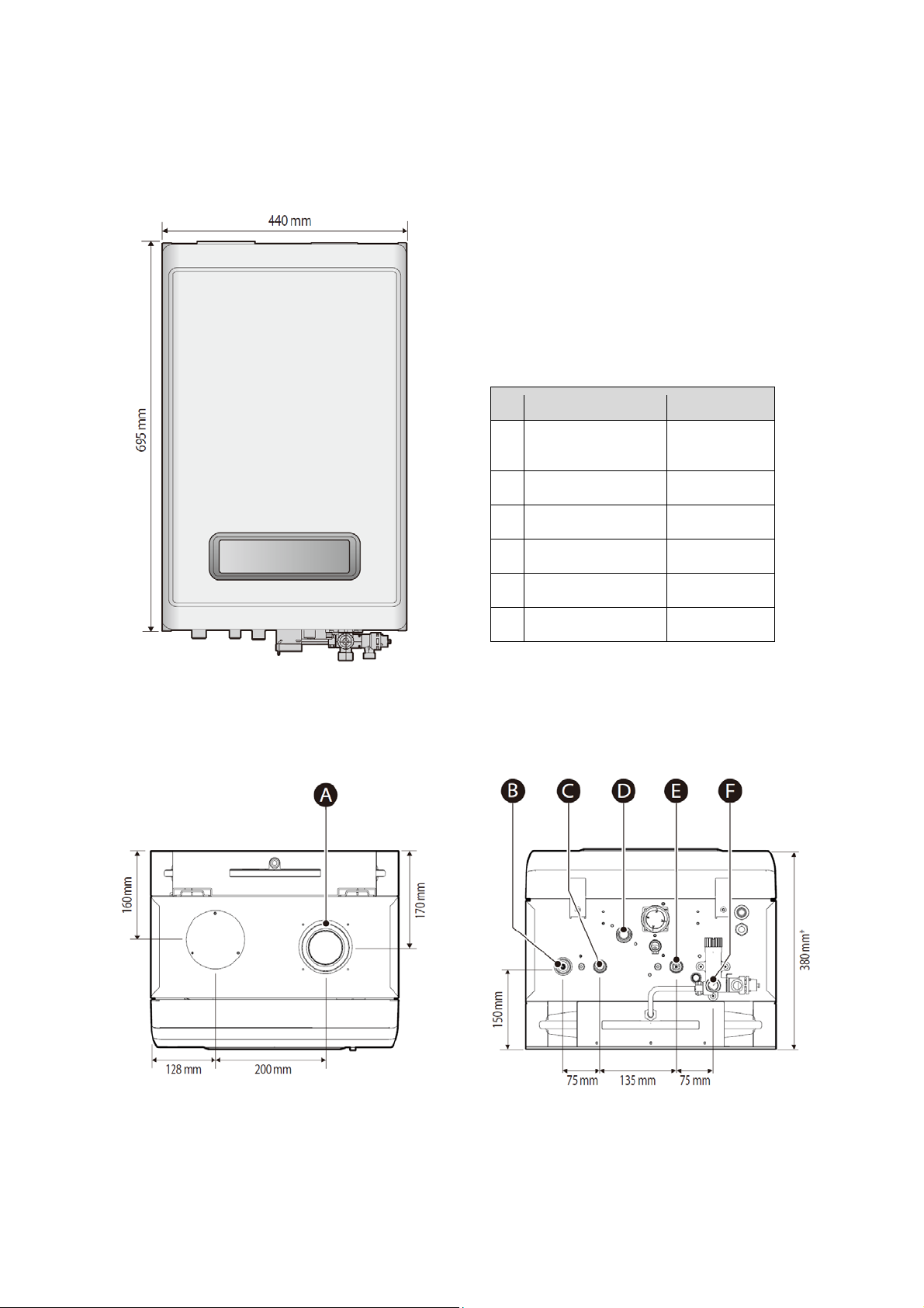
3.2 Dimensions
The following diagrams show the dimensions of the boiler. The table below lists the pipe diameters for various connection points.
Supply Connection Pipe Diameters
Overhead View
Re
A
B
C
D
E
F
Description Diameter
Flue exhaust/Air intake
Space heating supply 22 mm
Hot water outlet (DHW) 15 mm
Gas supply inlet 22 mm
Cold water inlet (DHW) 15 mm
Space heating return 22 mm
60 mm/100 mm,
80 mm/125 mm
Supply Connections
Version 1.0
* NCB-24LSWE/28LSWE: 350 mm
NCB-34LSWE/40LSWE: 380 mm
NCB Service Manual 19

4. System Details
4.1 Setting the DIP Switches
CAUTION
Do not remove the front cover
unless the power supply is turned
off or disconnected.
may result in electric shock.
The boiler has two sets of DIP switches on the main circuit
board (PCB) and two sets of DIP switches on the front
panel. DIP switches are used to control the boiler’s
functions. Set the DIP switches as required based on the
installation.
4.1.1 PCB DIP Switches
Setting the Circuit Board DIP Switches (8-way)
Failure to do so
Switch Function Setting
Normal operation 1-OFF, 2-OFF
1 & 2
3 & 4 Capacity
Operation
status
24/28/34
LSWE
40LSWE
24/28/34
LSWE
40LSWE
24/28/34
LSWE
40LSWE
DHW
MAX
DHW 2-
stage
MAX
MIN
1-stage
MIN
Heating
MAX
Heating
2-stage
MAX
24LSWE 3-OFF, 4-OFF
28LSWE 3-ON, 4-OFF
34LSWE 3-OFF, 4-ON
1-ON, 2-OFF
1-OFF, 2-ON
1-ON, 2-ON
The DIP switches on the circuit board configure the boiler’s
model and gas settings. These configurations are set at the
factory and should not be changed. The following tables
describe the functions of the DIP switches and their
settings.
40LSWE 3-ON, 4-ON
5
6 & 7 Region Europe 6-OFF, 7-OFF
Burner
type
Bekaert 5-ON
Alantum 5-OFF
Eg.) DIP Switch On/Off
20 NCB Service Manual
Version 1.0
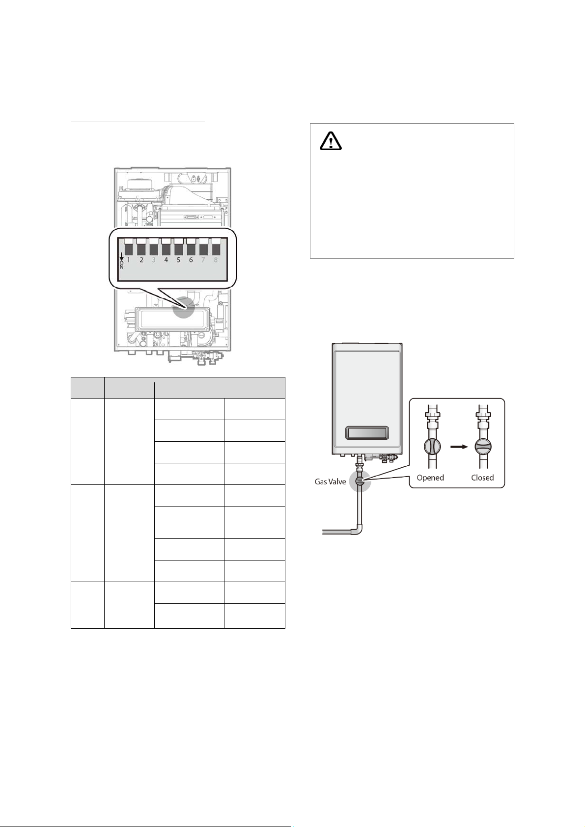
4.1.2 Front Panel DIP Switches
T
Setting the Front Panel DIP Switches
The DIP switch on the front panel configures the fuel
selection, source of the heat demand, and the temperature
control standard.
4.2 Measuring the Incoming Gas
Pressure
WARNING
The boiler does not function
correctly if there is insufficient
incoming gas pressure. Measuring
the inlet gas pressure should be
performed by a registered technician
only.
Switc
1 & 2
4 & 5
6
Function Setting
G20 (LNG) 1-OFF, 2-OFF
Fuel
selection
Heat
demand
Temperatu
re control
standard
G25, G27(LNG) 1-OFF, 2-ON
G30 (LPG) 1-ON, 2-OFF
G31 (LPG) 1-ON, 2-ON
Panel 2-OFF, 3-OFF
OpenTherm
Remote Control
hermostat 2-OFF, 3-ON
Panel 4-ON, 5-ON
Supply Water 1-OFF
Return Water 1-ON
2-ON, 3-OFF
* The incoming gas pressure must be between 17 mbar and 25
mbar for natural gas and between 25 mbar and 35 mbar for
liquefied propane.
To measure the incoming gas pressure:
1.
Shut off the manual gas valve on the gas supply line.
2.
Open a hot water tap. The boiler should turn on and
the gas in the gas supply line will be purged.
Leave the faucet on until the boiler shuts down due
3.
to the absence of gas, and then turn off the hot
water tap.
Version 1.0
NCB Service Manual 21
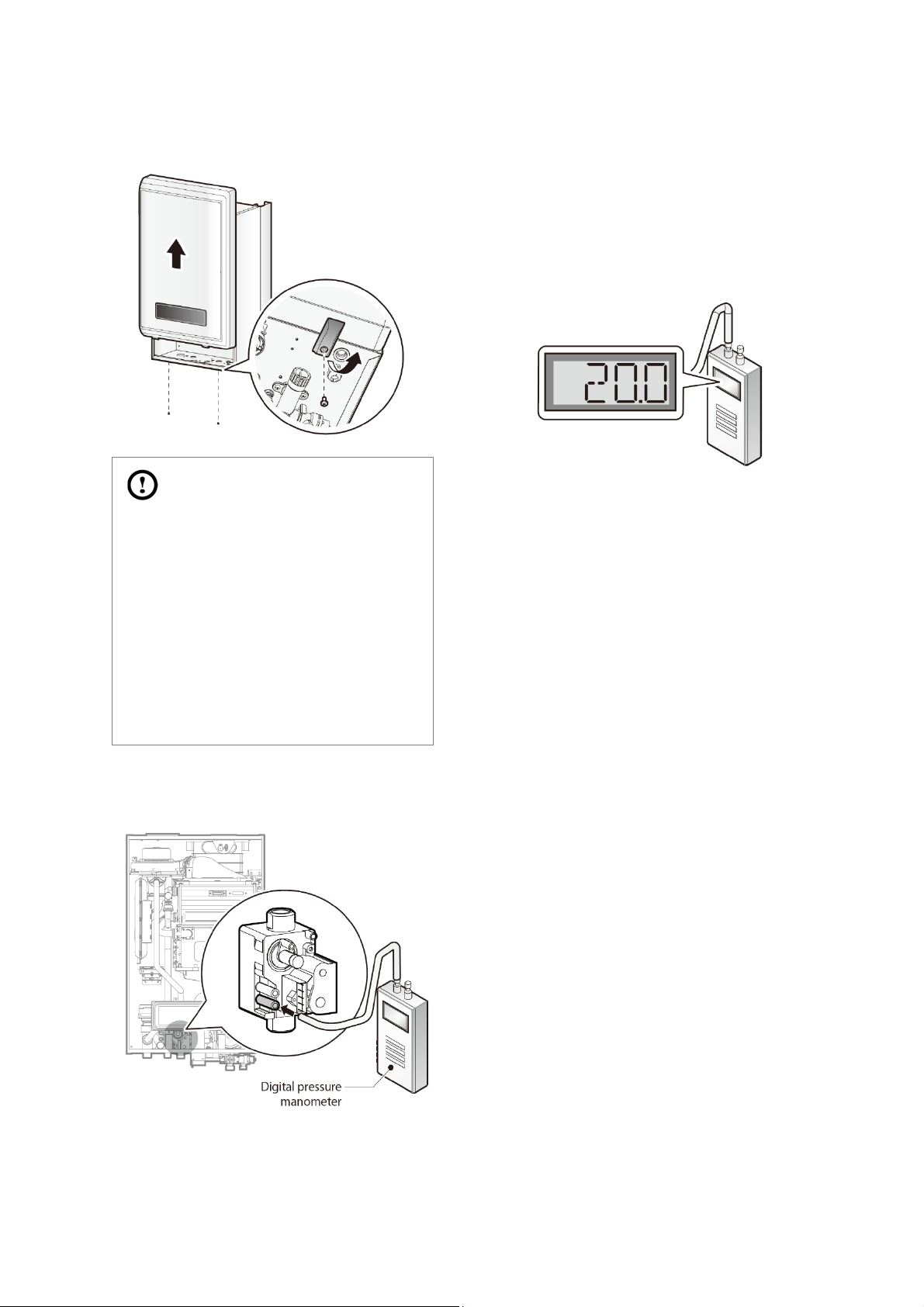
4. Remove the boiler’s front cover by loosening the 4
Phillips head screws securing it to the case.
Open multiple hot water outlets that that have high
7.
flow rates, such as bathtub taps and shower mixers,
to allow the boiler to operate at its maximum firing
rate.
When the boiler reaches the maximum firing rate,
8.
check the inlet gas pressure reading on the
manometer. The gas pressure must be within the
operating range listed in the specifications on page
17.
CAUTION
Ensure that no cables obstruct the
PCB assembly before inserting it in
position. If the assembly is stuck, do
not force it. Doing so may damage
the cables and result in serious
malfunction.
Check again to ensure that no cables
or any other parts obstruct the PCB
before proceeding.
5.
Loosen the screw indicated in the figure below and
connect a manometer to the pressure port. Reset the
manometer to zero before use.
Re-open the manual gas valve and check for leaks.
6.
22 NCB Service Manual
Version 1.0
4.3 Gas Conversion
This default gas supply configuration for this boiler is
Natural Gas. If it is converted to Propane Gas, the
conversion kit supplied with the boiler must be used.
Included Items:
Gas orifice specifications
Model NG LP
NCB-24LSWE Ø5.7 Ø4.5
WARNING
This conversion kit must be installed
by a qualified service agent*. All
conversions must be performed in
accordance with all applicable laws
and regulations. The information in
these instructions must be followed
to minimise the risk of fire or
explosion and to prevent property
damage, personal injury, or death.
The service agent is responsible for
the correct installation of the kit. The
conversion is not proper and
complete until the operation of the
converted appliance is checked as
specified in the manufacturer’s
instructions supplied with the kit.
* A qualified service agent is any individual, firm, corporation or
company who either in person or through a representative is
engaged in and is responsible for the connection, installation,
repair, or servicing of gas equipment or accessories. Qualified
service agents are experienced in gas appliance work,
familiar with all safety precautions, and has comply with all
applicable laws and regulations.
NCB-28LSWE Ø5.7 Ø4.5
NCB-34LSWE Ø5.9 Ø4.55
NCB-40LSWE Ø4.8/Ø6.05 Ø3.8/Ø4.7
Table 1. Orifice sizes
Gas pressure and conversion kit labels
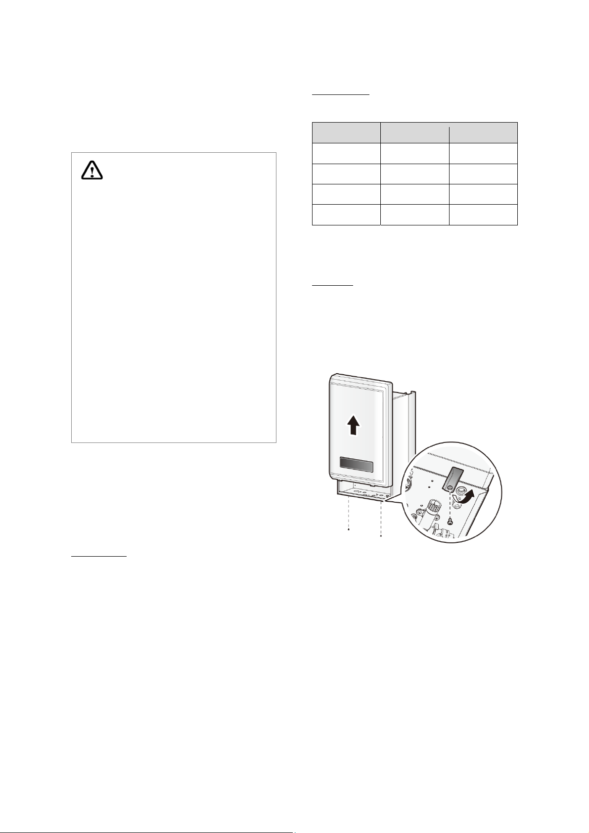
Procedure:
1. Turn off the gas and water supplies to the boiler.
2. Use a Phillips screwdriver to remove the two screws
(one at the left bottom and one at the right bottom)
from the front cover assembly to gain access to the
internal components. Refer to Figure 1 for an
illustration of the front cover on the unit.
Tools r
equired:
Phillips screwdriver
Flathead screwdriver
4 mm (5/32 in ) Allen wrench
Combustion analyzer or dual port manometer
Gas leak detector
Version 1.0
Figure1. B LSWE Series front cover
Remove the front cover and place it in a safe location
3.
to prevent accidental damage.
4.
Label all of the PCB wires.
5. Disconnect all wires from the PCB.
NCB Service Manual 23
6. Loosen the four screws indicated in the illustration
below.
Remove the PCB
7.
assembly.
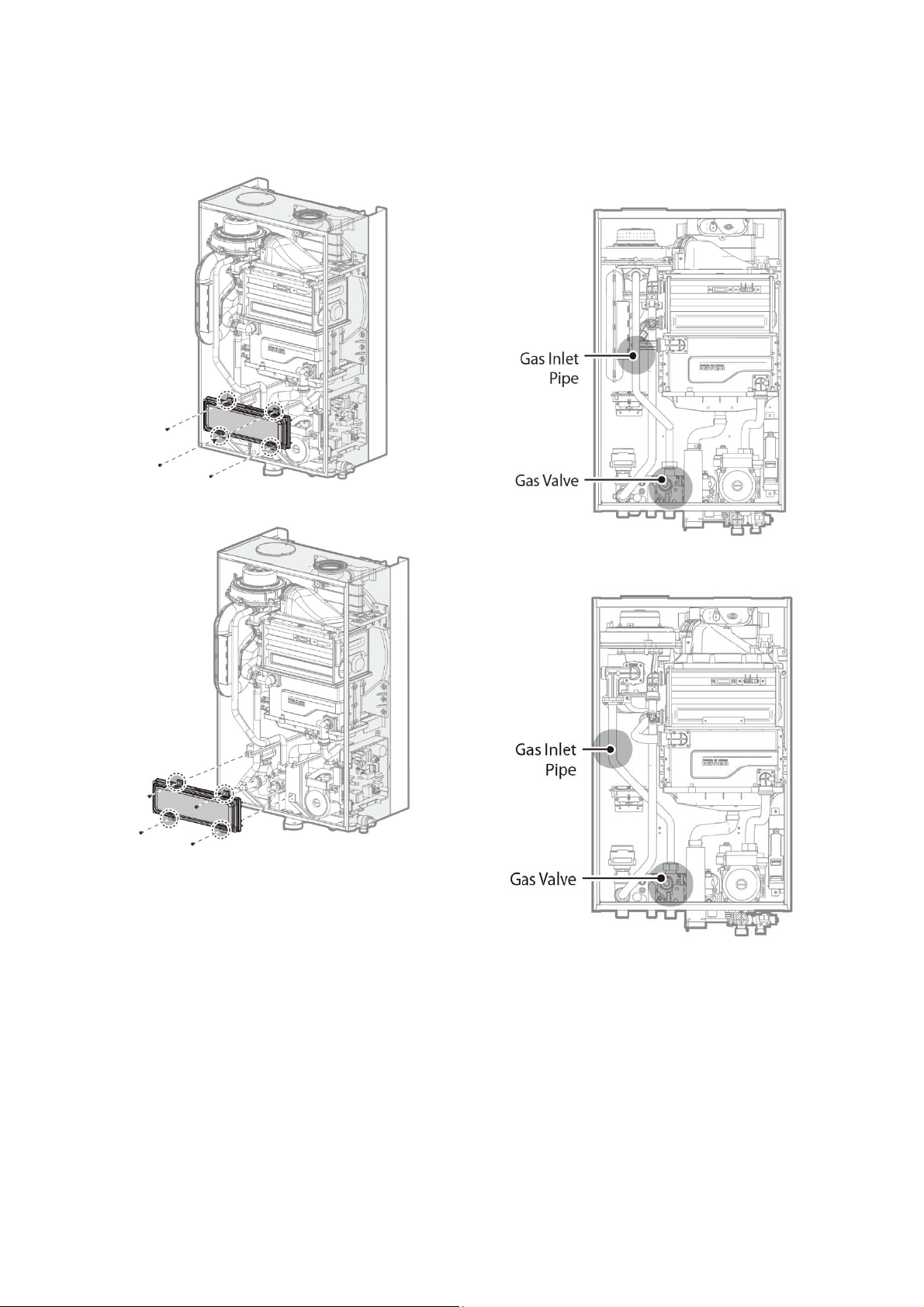
With the internal components exposed, locate the
8.
inlet
gas
unit
pipe and the gas valve
as
shown
in
Figure 2-1 and Figure
in
the middle
2-2.
Figure 2-1. NCB-24/28/34LSWE Internal Components
of
the
Figure 2-2. NCB-40LSWE Internal Components
24 NCB Service Manual
Version 1.0
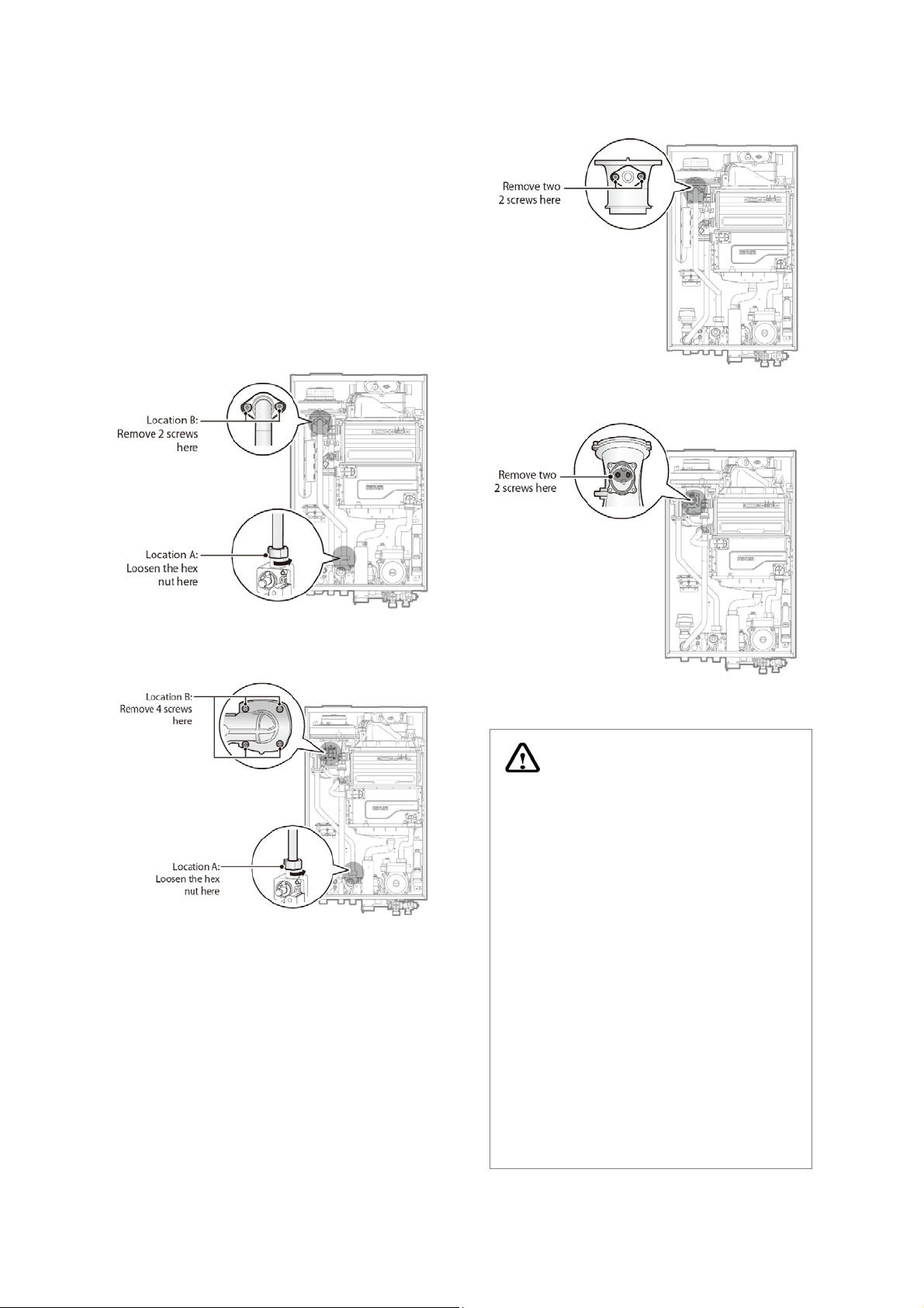
9.
Loosen the hex nut at location A - the connection
above the gas valve where it connects to the pipe
(refer to Figure 3-1 and Figure 3-2). When the hex nut
is loosened, carefully separate the pipe from the gas
valve.
Detach the gas inlet pipe from the gas valve and
10.
locate B - the connection above the gas valve where
it is attached to the fan motor assembly. Carefully
remove the two screws (four screws for NCB40LSWE) using a Phillips screwdriver. Then, pull the
gas inlet pipe out from the fan assembly to access
the gas orifice.
Figure 4-1. Access to Gas Orifice in Fan Assembly
(NCB-24/28/34LSWE)
Figure 3-1. Detaching Gas Inlet Pipe from
Gas Valve and Fan Motor Assembly (NCB-24/28/34LSWE)
Figure 3-2. Detaching Gas Inlet Pipe from
Gas Valve and Fan Motor Assembly (NCB-40LSWE)
When the gas orifice is exposed, remove the two screws
that hold it in place. Remove the orifice from its housing
and prepare the new LP orifice for installation.
Figure 4-2. Access to the gas orifice in fan assembly
(NCB-40LSWE)
WARNING
DO NOT adjust or attempt to
measure the outgoing gas pressure.
The gas valve is factory-set for the
correct
is
propane and does not require field
adjustment.
Attempting to adjust or measure
the gas valve outlet pressure
could result in damage to the
valve or other property, serious
personal injury, o r death
NCB LSWE
configured for
installations
outlet pressure. This setting
suitable
for
natural gas
boilers
are shipped
natural gas
ONLY.
and
. Navien
Version 1.0
NCB Service Manual 25
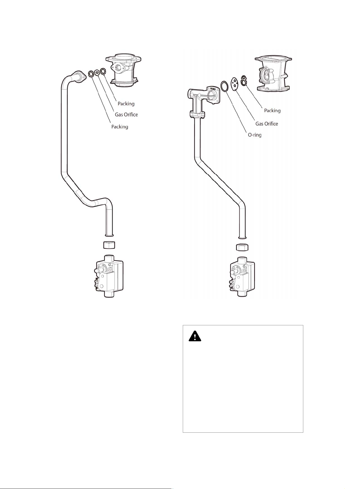
Figure 5-1. Exploded View of Gas Pipe Assembly
(NCB-24/28/34LSWE)
Figure 5-2. Exploded View of Gas Pipe Assembly
(NCB-40LSWE)
DANGER
See Figure 5-1. Inspect the O-ring
each time the connection between
the venturi and gas valve inlet
adapter is disassembled. The O-ring
must always be installed and also
must not be damaged. A missing Oring will cause a gas leak and can
result in serious personal injury or
fatality.
26 NCB Service Manual
Version 1.0
Replace the orifice with the new LP gas orifice. Ensure that
the orifice is seated properly inside the port before
proceeding to the next step.
11.
Reinstate the gas inlet pipe to its original position
and replace all of the screws and ensure all
connections are secure.
over tighten th e sc rews
DO NOT
components
12.
Refer to the labels carefully and then connect all the
wires.
13. Change the front panel Dip Switch settings for the
new gas type.
may be damaged
as
or cracked
WARNING
DANGER
When a gas conversion is performed,
ensure the front panel DIP switches
are set for the correct gas type.
.
Failure to properly set the DIP
switches can cause carbon
monoxide poisoning and result in
serious personal injury or death.
14. Turn on the gas and supply water to the boiler.
15.
Measure and adjust the gas/air ratio.
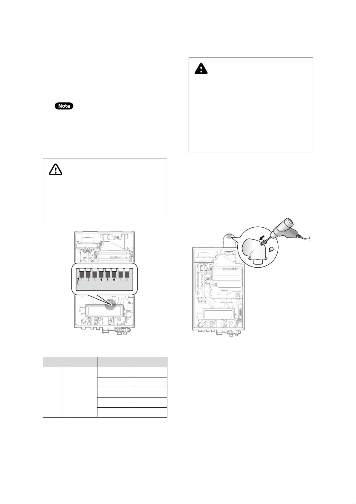
Ensure that you have turned off the
power to the boiler before opening
the front cover and accessing the DIP
switches
Figure 6. Set the DIP switches
Switch Function Setting
G20 (LNG) 1-OFF, 2-OFF
G25, G27(LNG) 1-OFF, 2-ON
1 & 2 Gas type
Table 1. The DIP Switch Setting by Fuel Selection
G30 (LPG) 1-ON, 2-OFF
G31 (LPG) 1-ON, 2-ON
G20 (LNG) 1-OFF, 2-OFF
Option 1. Combustion analyser (recommended)
Loosen the screw, rotate the plate, and then
a.
remove the gasket to access the emissions
monitoring port as shown in Figure 8.
b.
Insert the analyser into the port (Figure 8).
Figure 7. Insert the Analyser
Version 1.0
NCB Service Manual 27
Model
NCB-24LSWE
NCB-28LSWE
NCB-34LSWE
NCB-40LSWE
(CO2 values at high flame settings must be within 0.5% and
CO2 values for low flame settings must be within 0.3% of
Fully open several hot water outlet fittings and
c.
set the boiler to operate at Stage 1MIN mode.
Measure the CO2 value at the low flame setting. If the CO2
value is not within 0.5% of the value listed in Table 2, adjust
the gas valve set screw. If set screw adjustment is required,
locate the screw as shown in Figure 9. Use a 4 mm (5/32 in)
Allen wrench and turn the set screw no more than 1/4 turn
clockwise to increase or anticlockwise to decrease the CO
value.
Gas Type
G20
Max
% CO
9.27%
G31
10.40%
G20
9.20%
G31
10.42%
G20
9.10%
G31
10.30%
G20
9.20%
G31
10.50%
Table 2. CO2 Value
the values listed.)
Refer to page 55 for information about
selecting operating modes.
Min
% CO
8.78%
10.00%
8.65%
10.00%
8.50%
9.90%
8.70%
10.40%
2
d. Fully open several hot water outlet fittings and
set the boiler to operate at 2-stage MAX mode
(refer to page 55). Measure the CO2 value at a
high flame setting. If the CO2 value does not
match the values listed in Table 2 at a high flame
setting, do not adjust the gas valve. Check that
the orifice is the correct specification.
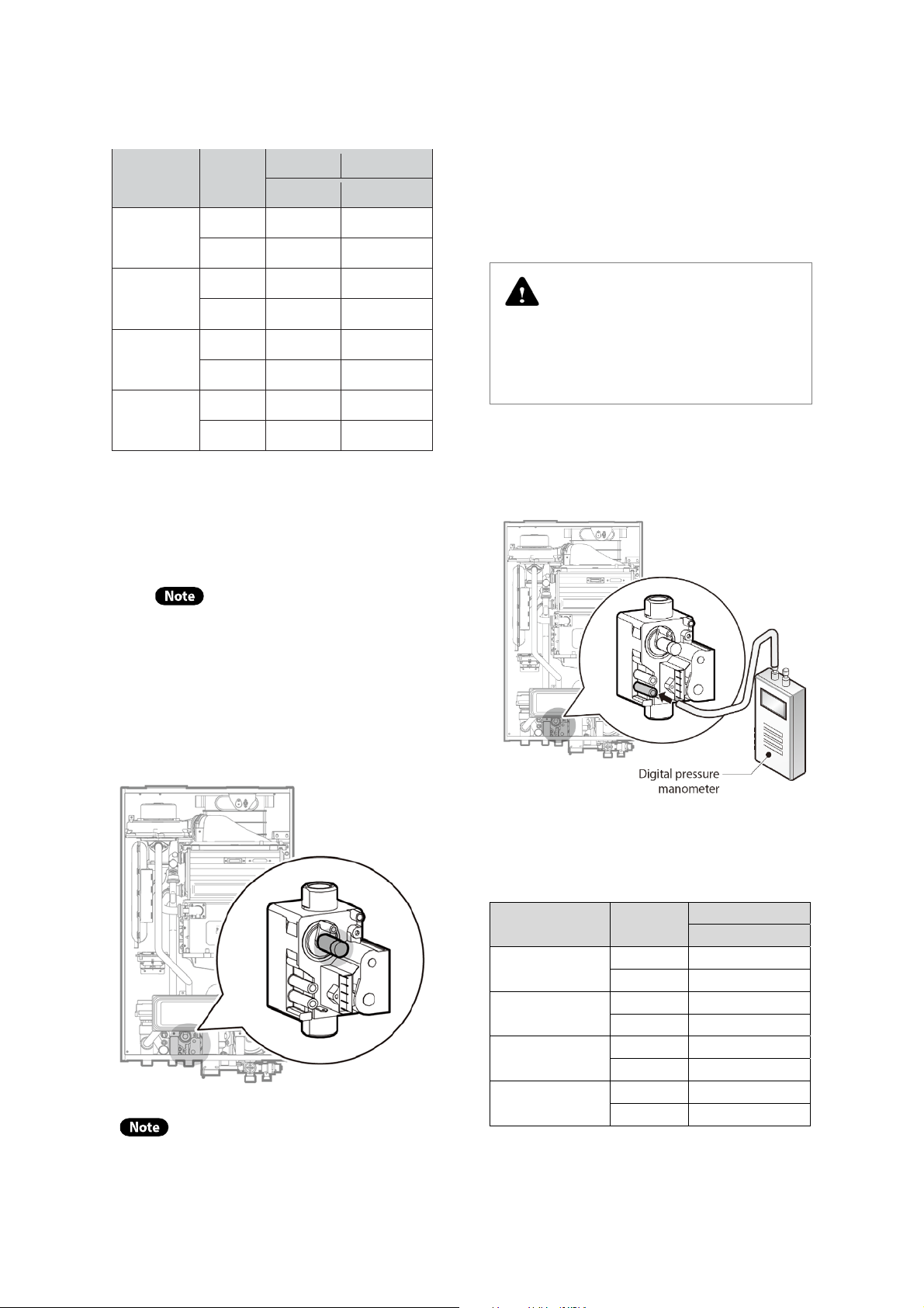
DANGER
Improper gas valve settings can
cause property damage, serious
personal injury, or death.
Option 2. Digital manometer
a.
Open the offset pressure port by loosening the
screw two turns. The location of the offset port is
shown in Figure 10.
Figure 9. Digital pressure manometer connection
b. Connect a manometer to the offset pressure port.
For dual port manometers, use the positive
pressure side.
Model Gas Type
NCB-24LSWE
NCB-28LSWE
NCB-34LSWE
Figure 8. Set screw location
The set screw is located behind a
removable cover. To access the set screw,
loosen the screws and remove the cover.
28 NCB Service Manual
NCB-40LSWE
Table 3. Minimum offset values
G20 8 ± 1
G31 4 ± 1
G20 8 ± 1
G31 4 ± 1
G20 8 ± 1
G31 4 ± 1
G20 8 ± 1
G31 4 ± 1
Minimum Offset
Pa
Version 1.0
 Loading...