

Navien NCB-150E, NCB-180E, NCB-210E, NCB-240E Service Manual

Getting Service
If your boiler requires service, you have several options for getting service:
●
Contact Technical Support at 1-800-519-8794 or on the website: www.navienamerica.com.
For warranty service, always contact Technical Support first.
●
Contact the technician or professional who installed your boiler.
●
Contact a licensed professional for the affected system (for example, a plumber or electrician).
When you contact Technical Support, please have the following information at hand:
●
Model number
●
Serial number
●
Date purchased
●
Installation location and type
●
Error code, if any appears on the front panel display.
Navien, Inc.
800.519.8794
www.Navien.com
20 Goodyear lrvine, CA 92618
Service Manual
NCB-E Condensing Combi Boiler
THE LEADER IN CONDENSING TECHNOLOGY
Version: 1.4 (Oct 26, 2015)
WARNING
If the information in these instructions is not followed exactly, a fire or explosion may result, causing
property damage, personal injury, or death.
Do not store or use gasoline or other flammable vapors and liquids in the vicinity of this or any other
appliance.
WHAT TO DO IF YOU SMELL GAS
●
Do not try to light any appliance.
●
Do not touch any electrical switch; do not use any phone in your building.
●
Immediately call your gas supplier from a neighbor’s phone. Follow the gas supplier’s instructions.
●
If you cannot reach your gas supplier, call the fire department.
Installation and service must be performed by a qualified installer, service agency or the gas supplier.
The installation must conform with local codes or, in the absence of local codes, the National Fuel Gas
Code, ANSI Z223.1/NFPA 54 and/or CSA B149.1, Natural Gas and Propane Installation Code.
When applicable, the installation must conform with the Manufactured Home Construction and
Safety Standard, Title 24 CFR, Part 3280 and/or CAN/CSA Z240 MH Series, Mobile Homes.
H
NSF/ANSI 372
Keep this manual near this boiler for future reference
whenever maintenance or service is required.
* The wetted surface of this product contacted by consumable water contains less than
one quarter of one percent(0.25%) of lead by weight.
Service Manual
NCB-E Condensing Water Heaters
Model
NCB-150E
NCB-180E
NCB-210E
NCB-240E

Revisions 3
Version Description of changes Date
1.00 First Issue October/27/2013
1.10 Cascade information addition January/03/2014
1.20 E001 information addition, E205 information revision June/12/2014
1.30 AFUE Change November/24/2014
1.40 NCB-150E,180E,210E and 240E Model Added September/30/2015
1.10 Reviewed BY :
1.20 Reviewed BY : Paek Ji Ho
Revisions

Version 1.4
4 NCB-E Service Manual
1. Safety Information 10
1.1 Safety Definitions 10
1.2 Safety Symbols
10
1.3 Symbols Used in the Instructions
10
1.4 Safety Precautions
10
2. Product Information 14
2.1 Product Information 14
2.2 Components
15
3. Technical Data 17
3.1 General Specifications 17
3.2 Dimensions
19
4. System Details 20
4.1 Setting the DIP Switches 20
4.1.1 Setting the DIP Switches 20
4.2 Measuring the Inlet Gas Pressure 22
4.2.1 Gas Pipe Sizing Tables
(Referenced from 2012 National Fuel Gas Code)
24
4.3 Gas Conversion 26
4.4 The Front Panel
32
4.4.1 Icons and Digital Display 32
4.4.2 Buttons
33
4.4.3 Turning the Boiler On or Off
35
4.4.4 Normal Operation
35
4.4.5 Error Display and RESET
37
4.4.6 Adjusting the Space Heating Temperature
37
4.4.7 Adjusting the DHW Temperature
38
4.4.8 Viewing Basic Information (For Homeowner)
39
4.4.9 Error occurrence history display
41
4.4.10 Information display (for servicer)
42
4.4.11 Special Parameter mode
47
4.4.12 Resetting the Boiler (Factory Reset)
57
4.4.13 Cascade Protocol Settings
57
4.4.14 Cascade Set-up Procedure
58
4.4.15 Cascade Set-up Procedure for NP/NR Series Models
58
4.5 Version Display 59
4.6 Error Codes
59
4.7 Ladder Diagram
60
4.8 Electrical Diagnostic Point & Wiring Diagram
61
4.9 Key Components Description 64
4.9.1 PCB 64
4.9.2 High Limit Switch
65
4.9.3 Thermistor
66
4.9.4 Fan Motor
67
4.9.5 Flame Rod Assembly
68
4.9.6 Ignition Transformer
69
4.9.7 APS
70
4.9.8 Main Gas Valve
71
4.9.9 Burner
72
4.9.10 Flow Sensor
73
4.9.11 Primary Heat Exchanger
74
4.9.12 Secondary Heat Exchanger
75
4.9.13 DHW Heat Exchanger
76
4.9.14 Circulation Pump
77
4.9.15 3-Way Valve
78
4.9.16 Water Pressure Sensor
79
4.9.17 Auto feeder Valve
80
4.9.18 Dual Venturi
81
5. Troubleshooting 82
5.1 Error code classification 82
5.2 Error Code List
83
5.1.1 001Error 86
5.2.2 003Error
89
5.2.3 004Error
95
5.2.4 012Error
97
5.2.5 016Error
101
5.2.6 030Error
103
5.2.7 046Error
105
5.2.8 047Error
105
5.2.9 060Error
106
5.2.10 109Error
108
5.2.11 110Error
110
5.2.12 205Error
112
5.2.13 218Error
114
5.2.14 351Error
116
5.2.15 352Error
118
5.2.16 353Error
119
5.2.17 407Error
120
5.2.18 421Error
122
5.2.19 439Error
124
5.2.20 515Error
126
5.2.21 517Error
127
5.2.22 594Error
127
5.2.23 615Error
127
5.2.24 740Error
128
5.2.25 777Error
129
5.2.26 782Error
130
5.3 Troubleshooting guide by symptom 131
5.3.1 Noise 131
5.3.2 Water Temperature Issue
132
5.3.3 Circuit breaker operation
133
Contents

Contents 5
6. Replacement of Parts 134
6.1 Replacement Procedure 134
6.2 Components Replacement Instructions
134
6.2.1 PCB 134
6.2.2 Fuse
135
6.2.3 Fan Motor (Combustion Air)
135
6.2.4 Flame Rod
136
6.2.5 Ignition Transformer
137
6.2.6 APS
137
6.2.7 Main Gas Valve
138
6.2.8 Condensate Trap
139
6.2.9 Flow Sensor
140
6.2.10 Circulation Pump
141
6.2.11 3-way Valve
142
6.2.12 Water Pressure Sensor
143
6.2.13 Space Heating Strainer
143
6.2.14 Auto Feeder Valve
144
6.2.15 DHW Heat exchanger
144
7. Components Diagram and Part List 145
7.1 Case Assembly 145
7.2 Burner Assembly
146
7.3 Waterway Assembly (NCB)
148
7.4 Waterway Assembly (NCB-E)
150
7.5 Fan (Gas) Assembly
152
8. Inspection and Maintenance Schedule 154
8.1 Annual Servicing 154
8.2 Maintenance Report
154
8.3 Maintenance Schedules
154
8.4 Inspection Report
154

Version 1.4
6 NCB-E Service Manual
Requirements for the State of Massachusetts
This appliance must be installed by a licensed plumber or gas fitter in accordance with the Massachusetts Plumbing and Fuel Gas Code 248
CMR Sections 2.00 and 5.00.
IMPORTANT: In the State of Massachusetts (248 CMR 4.00 & 5.00)
For all side wall horizontally vented gas fueled equipment installed in every dwelling, building or structure used in whole or in part for
residential purposes, including those owned or operated by the Commonwealth and where the side wall exhaust vent termination is less than
seven (7) feet above finished grade in the area of the venting, including but not limited to decks and porches, the following requirements shall
be satisfied:
1. INSTALLATION OF CARBON MONOXIDE DETECTORS. At the time of installation of the side wall horizontal vented gas fueled equipment,
the installing plumber or gasfitter shall observe that a hard wired carbon monoxide detector with an alarm and battery back‐up is
installed on the floor level where the gas equipment is to be installed. In addition, the installing plumber or gasfitter shall observe that a
battery operated or hard wired carbon monoxide detector with an alarm is installed on each additional level of the dwelling, building or
structure served by the side wall horizontal vented gas fueled equipment. It shall be the responsibility of the property owner to secure the
services of qualified licensed professionals for the installation of hard wired carbon monoxide detectors
a. In the event that the side wall horizontally vented gas fueled equipment is installed in a crawl space or an attic, the hard wired carbon
monoxide detector with alarm and battery back‐up may be installed on the next adjacent floor level.
b. In the event that the requirements of this subdivision cannot be met at the time of completion of installation, the owner shall have a
period of thirty (30) days to comply with the above requirements; provided, however, that during said thirty (30) day period, a battery
operated carbon monoxide detector with an alarm shall be installed.
2. APPROVED CARBON MONOXIDE DETECTORS. Each carbon monoxide detector as required in accordance with the above provisions shall
comply with NFPA 720 and be ANSI/UL 2034 listed and IAS certified.
3. SIGNAGE. A metal or plastic identification plate shall be permanently mounted to the exterior of the building at a minimum height of eight
(8) feet above grade directly in line with the exhaust vent terminal for the horizontally vented gas fueled heating appliance or equipment.
The sign shall read, in print size no less than one‐half (1/2) inch in size, “GAS VENT DIRECTLY BELOW. KEEP CLEAR OF ALL OBSTRUCTIONS”.
4. INSPECTION. The state or local gas inspector of the side wall horizontally vented gas fueled equipment shall not approve the installation
unless, upon inspection, the inspector observes carbon monoxide detectors and signage installed in accordance with the provisions of
248 CMR 5.08(2)(a)1 through 4.

7
Warranty Exclusions
Navien’s Limited Warranty shall be void in the event of an
occurrence of any of the following:
●
Improper installation, failure to install in strict compliance with
the Installation Manual procedures, installed by a non-licensed
installer, and installation in violation of applicable rules, laws or
building codes.
●
Product purchased through the internet, other e-commerce
channels, or any installer that obtained the Product from a
supplier or distributor not authorized by Navien.
●
Failure to perform regular maintenance, misuse, operation at
settings other than those recommended or specified, noncompliance with instructions or guidelines set forth in the User’s
Operation Manual.
●
Modification or alteration of the Product in any manner,
including but not limited to, removal of any component or
part, addition of any non-approved components, relocating
or moving the Product from its original installation site, or any
accidental or intentional damage to the Product.
●
Installation in commercial or multi-unit dwelling applications or
for non-recommended uses.
●
Any damage caused by local adverse conditions including but
not limited to hard water deposits, lime or mineral build-up,
operating in corrosive atmospheric elements.
●
Damage or caused by gas flow issues, electrical surges, flooding,
fire, abnormal external temperature, and any other cause of
damage not directly caused by a manufacturing defect.
●
Installer’s failure to fully comply with the Warranty Service and
Return Policy procedures previously provided to Installer and
as is available on Navien’s website. Such policies include but
are not limited to the Installer’s failure to first contact Navien
Technical Support while in front of the product for purposes of
trouble shooting the identified problem or issue.
●
Performance problems caused by improper sizing of the boiler,
the gas supply line, the venting connection, combustion air
openings, electric service voltage, wiring, fusing or any other
components, parts or specifications.
●
Improper conversion from natural gas to LP gas or LP gas
to natural gas or attempt to operate with a type of gas not
specified for the boiler.
●
Any damage, malfunction or failure caused by abuse,
negligence, alteration, accident, fire, flood, freezing, wind,
lightning and other acts of God.
●
Operating, using or storing the boiler in a corrosive or
contaminated atmosphere or environment.
●
Operating the boiler at water temperatures outside the factory
calibrated temperature limits and/or exceeding the maximum
setting of the high limit control.
●
Operating the boiler when it is not supplied with potable water
at all times.
●
Subjecting the heat exchanger to pressures or firing rates
greater or lesser than those shown on the rating plate.
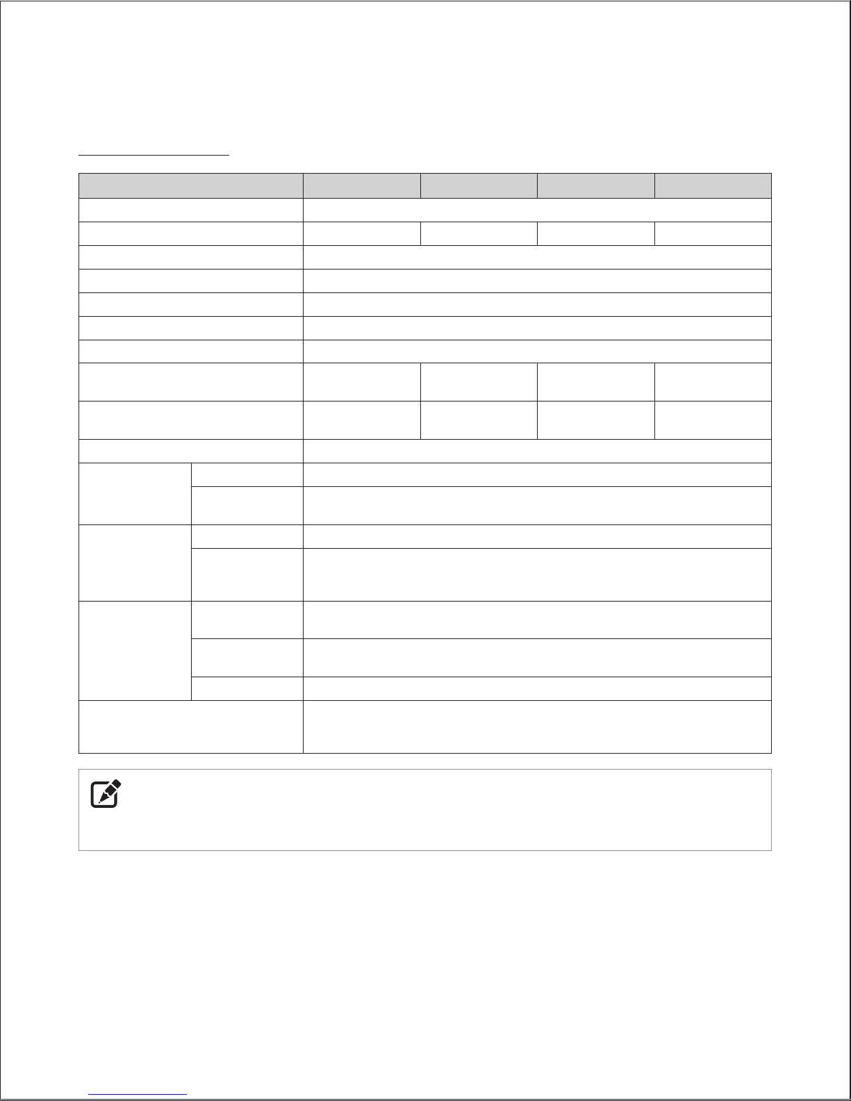
Warranty Period
Navien products come with a limited warranty covering labor,
parts and the heat exchanger. The following warranty periods
begin to run from the date of original installation. The date of
original installation must be provided to Navien, and upon request,
proof of the original installation date must also be provided to
Navien. When the product is installed in a new construction, the
commencement date shall be dated upon which the end-user
takes title to the property.
APPLICABLE WARRANTY PERIOD
Product
Labor
Warranty
Parts
Warranty
Heat
Exchanger
Warranty
NCB-E Series Boiler
(Single Family
Residential Use)
1 Year 5 Years 10 Years
Warranty Claim Procedures
To obtain warranty repair service, the end user or homeowner
must contact the original installer of your Navien product. If the
original installer cannot be identified, the end user or homeowner
may contact Navien’s Technical Administration Department at
(800) 519-8794. Proof of purchase is required to obtain warranty
service.
Warranty Service
At its option, Navien will replace the defective component (part(s)
or heat exchanger), in accordance with the terms of this Limited
Warranty, if it fails in normal use and service during the Applicable
Warranty Period identified above. The replacement component
must be Navien original factory component. Navien, at its sole
discretion, may replace the product with a new or refurbished
product of comparable quality and design. The replacement
component or product will be warranted only for the unexpired
portion of the original component’s Applicable Warranty Period.
Payment for labor in completing the warranty service is subject
to Navien’s prior written approval and shall be subject to Navien’s
schedule of approved labor allowances.
Navien Warranty
Version 1.4
8 NCB-E Service Manual
●
Installation at any location outside the United States and
Canada.
●
Removal or alteration of the rating plate.
Rating Plate, *Plaque Signalétique
Combination Boiler *Chaudière combinaison
Navien, Inc.
20 Goodyear, Irvine, CA 92618
Tel: 1-800-519-8794
Direct vent indoor installation, * Évacuation directe installation intérieure
Model No., *Numéro de modèle Type of Gas, *Type de gaz
NCB-240E NG
Max. Input Rating (DHW),*Entrée GPL max. Min. Input Rating,*Débit calorifique max.
199,900 Btu/h 18,000 Btu/h
Max. Input Rating
(Heating),*Entrée GPL max. Heating Capacity, *Capacité de chauffage
120,000 Btu/h 112,000 Btu/h
Category of boiler, *Catégorie de chaudière Net AHRI Rating, *Régime de AHRI
Category IV 97,000 Btu/h
Max. Inlet Gas Pressure, *Pression max. de gaz d’entrée 10.5 Inches W.C. *pouces W.C.
Min. Inlet Gas Pressure, *Pression min. de gaz d’entrée 3.5 Inches W.C. *pouces W.C.
Manifold Pressure, *Pression d’admiss
ion -1.20 Inches W.C. *pouces W.C.
Electrical Rating, *Régime nominal électrique AC*c.a. 120 Volts 60Hz Use less than 2 Amp, *Utilise moins de 2A
Minimum relief valve capacity, *Capacité minimaum soupape. 189 lbs/hr ANSI Z21.13b-2014 · CSA 4.9b-2014
Orifices necessary for LP conversion are provided. *Les injectures nécessaires à la conversion au GPL sont fournis.
Failure to use the correct gas can cause pro
blems which can result in death, serious injury or property damage.*Le f ait de ne pas
utiliser le bon gaz peut causer des problèmes qui peuvent mener à la mort, causer des blessures graves ou endommager la propriété.
Consult your installation manual for more information.*Consultez votre manuel d’installation pour plus d’information.
This appliance is certified for use at altitudes up to 4,500 ft (1,
370 m) in accordance to the latest CAN/CGA 2.17-High Altitude
Installation procedures at normal manifold pressure. For installation instructions at altitudes higher than 4,500 ft, please contact
Navien. *Cet appareil est certifié pour une utilisation à des altitudes de 0 à 4,500 pieds (1,370 m) conformément aux toutes les procédures
d’installation à haute altitude CAN/CGA 2.17 à une pression normal
e. Pour les installations à élévations en haut de 4,500 pieds, appeler le
bureau de Navien.
This appliance must be installed in accordance with local codes or in the absence of local codes, the most recent edition of
National Fuel Gas Code, ANSI Z223. 1, in Canada use CAN/CGA B149. 1 or 2 installation codes for Gas Burning Appliances.
*Cet appareil doit être installé conformément aux codes locaux, ou
s’il n’y a pas de codes locaux, la plus récente version du National Fuel
Gas Code des É.-U., ANSI Z223. 1, au Canada utilisez les codes d’installation CAN/CGA B149. 1 ou 2 pour les appareils à gaz.
FOR YOUR SAFETY *POUR VOTRE SÉCURITÉ
Do not store or use gasoline or other flammable vapors and liquids in the vicinity of this or any other gasappliances. *Ne rangez
pas et n'utilisez pas d'essence ou d'a
utres liquides ou vapeurs inflammables près de cet appareil ou de tout autre appareil électroménager.
Other Terms: This Limited Warranty is subject further to the terms
and conditions set forth herein and as may be further specified
in the Terms and Conditions page located on Navien’s website at
www.navienamerica.com. WITH THE EXCEPTION OF THIS LIMITED
WARRANTY, NAVIEN DISCLAIMS ANY OBLIGATION OR LIABILITY
WITH RESPECT TO THE PRODUCTS OR THEIR SALE AND USE, AND
NAVIEN NEITHER ASSUMES NOR AUTHORIZES THE ASSUMPTION
OF, ANY OBLIGATION OR LIABILITY IN CONNECTION WITH THE
PRODUCTS. THIS DISCLAIMER INCLUDES ANY OTHER WARRANTIES,
EXPRESS, IMPLIED OR STATUTORY RESPECTING THE PRODUCTS
OR ANY PARTS OR COMPONENTS THEREOF, INCLUDING, BUT NOT
LIMITED TO, ANY IMPLIED WARRANTY OF MERCHANTABILITY
OR FITNESS FOR A PARTICULAR PURPOSE. Navien’s total liability
for any claim arising hereunder shall not exceed the purchase
price which you paid for the Product. NAVIEN SHALL NOT IN ANY
EVENT BE LIABLE FOR INDIRECT, SPECIAL, CONSEQUENTIAL OR
LIQUIDATED DAMAGES OR PENALTIES, INCLUDING CLAIMS FOR
LOST REVENUE, PROFITS OR BUSINESS OPPORTUNITIES, EVEN IF
NAVIEN HAD OR SHOULD HAVE HAD ANY KNOWLEDGE, ACTUAL
OR CONSTRUCTIVE, OF THE POSSIBILITY OF SUCH DAMAGES.
9
Abbreviation Definition
NCB-E General name of NCB-180E, NCB-210E, and NCB-240E
NG Natural Gas
LP Propane Gas
AP Air Pressure
APS Air Pressure Sensor
DHW Domestic Hot Water
FM Fan Motor
GARC Gas Air Ratio Control
GPM Gallons Per Minute
MGV Main Gas Valve
RPM Revolutions Per Minute
PCB Printed Circuit Board
EMI Electromagnetic Interface
HTL High Temperature Limiter
LWCO Low Water Cut Off
Abbreviations and Definitions
Version 1.4
10 NCB-E Service Manual
1.1 Safety Definitions
The following safety symbols are used in this manual. Read and
follow all safety instructions in this manual precisely to avoid unsafe
operating conditions, fire, explosion, property damage, personal
injury, or death.
1.2 Safety Symbols
DANGER
Indicates an imminently hazardous situation which, if not
avoided, could result in severe injury or death.
WARNING
Indicates a potential hazardous situation which, if not avoided,
could result in injury or death.
CAUTION
Indicates an imminent hazardous situation which, if not
avoided, may result in minor or moderate injury.
1.3 Symbols Used in the Instructions
The following symbols are used throughout the instructions to
bring attention to important information concerning the appliance.
IMPORTANT
Warns of a risk of damage and environmental pollution
NOTE
Indicates additional information that is important but not
related to personal injury or property damage.
1.4 Safety Precautions
DANGER
FLAMMABLE MATERIALS
Keep the area around the boiler clear and free from flammable
materials.
●
DO NOT place flammable liquids such as oils or gasoline, etc.
near the boiler.
●
DO NOT place combustibles such as newspapers and
laundry etc. near the boiler or the venting system.
●
DO NOT place or use hair spray, spray paint or any other type
of spray can near the boiler or the venting system (including
the vent termination).
●
DO NOT place anything in or around the vent terminations
that could obstruct the air flow in and out of the boiler such
as a clothes line.
DANGER
FLAMMABLE VAPORS
Vapors from flammable liquids will explode and catch fire
causing death or severe burns.
Do not use or store flammable products such as gasoline,
solvents or adhesives in the same room or area near the boiler.
●
Keep flammable products: far away from the boiler in
approved containers, tightly closed, and out of children’s
reach.
●
Boiler has a main burner flame: which can come on at any
time, and may ignite flammable vapors.
●
Vapors: cannot be seen, are heavier than air, go a long way
on the floor and can be carried from other rooms to the
main burner flame by air currents.
1. Safety Information
Safety Information 11
DANGER
HOT
BURN
HOT WATER TEMPERATURE SETTING
●
Water temperatures at or above 125°F (52°C) can cause
severe burns instantly or death from scalds.
●
Households with small children, disabled, or elderly persons
may require 120 °F (49°C) or lower temperature setting to
prevent contact with “HOT” water.
TO PREVENT BURNS
●
Use the lowest operating temperature setting necessary to
provide comfortably-hot water.
●
If your household has children or elderly or disabled
residents, consider using a lower temperature setting.
●
Read all the instructions in this manual carefully before
changing the temperature setting.
●
Feel the water before using it on children, the elderly, or the
disabled.
●
Contact a licensed plumber or your local plumbing authority
for more information.
●
This boiler’s water temperature is set to 120°F (49°C) at
the factory for your safety and comfort. Increasing the
temperature increases the risk of accidental scalding. Water
temperatures at or above 125°F (52°C) can cause instant
scalding, severe burns or death. Before you decide to change
the temperature setting, read the following charts carefully.
Water Temperature
Time in which a young child can suffer
a full thickness (3rd degree) burn
160°F (70°C) Less than 1 second
140°F (60°C) 1 second
130°F (55°C) 10 second
120°F (49°C) 10 minutes
100°F (37°C) very low scald risk
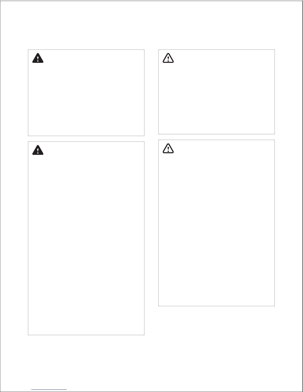
DANGER
COMPROMISED VENTING SYSTEM
●
Failure to follow the Venting Section of the installation
manual may result in unsafe operation of this boiler. To
avoid the risk of fire, explosion or asphyxiation from carbon
monoxide, never operate the boiler unless it is properly
vented to the outside and has an adequate air supply for
proper operation.
●
Be sure to inspect the vent termination and the air intake
pipe annually to ensure safe operation of the boiler.
●
Immediately turn off and do not use the boiler if any of the
vent pipes, vent elbows and/or the boiler are:
-
damaged in any way;
-
separated at a joint,
-
cracked or show evidence of corrosion, rusting or
melting.
DANGER
WHAT TO DO IF YOU SMELL GAS
If you do not follow these instructions exactly, a fire or
explosion may result causing property damage, personal
injury or loss of life.
DO NOT OPERATE THE BOILER.
DO NOT OPERATE ANY FAUCETS.
Smell all around the appliance area for gas. Be sure to smell
next to the floor because some gas is heavier than air and will
settle on the floor.
●
Do not smoke.
●
Extinguish any open flames and sparks.
●
Do not operate light switches or electrical equipment
switches.
●
Do not use any phone in your building.
●
Open the windows and doors.
●
Close the gas shutoff valve.
●
Keep people away from the danger zone.
●
Observe the safety regulations of your local gas supplier,
found on the gas meter.
●
Immediately call your gas supplier from the outside of the
building. Follow the gas supplier’s instructions.
●
If you cannot reach your gas supplier, call the fire department.
●
Notify your plumbing/heating contractor from the outside
of the building.
Version 1.4
12 NCB-E Service Manual
WARNING
GAS TYPE and AC VOLTAGE
This boiler is configured for Natural Gas from the factory. If
conversion to Propane Gas is required, the conversion kit
supplied with the boiler must be used.
●
Be sure to use 120 VAC, 60 Hz, minimum 2 A current. Using
abnormally high or low AC voltage may cause abnormal
operation, and may reduce the life expectancy of this
product.
If the unit does not match requirements, do not service,
please contact Navien immediately.
WARNING
GAS CONVERSION
The conversion kit shall be installed by a qualified service
agency* in accordance with Navien America’s instructions and
all applicable codes and requirements of the authority having
jurisdiction. The information in these instructions must be
followed to minimize the risk of fire or explosion or to prevent
property damage, personal injury or death. The qualified
service agency is responsible for the proper installation of
this kit. The installation is not proper and complete until the
operation of the converted appliance is checked as specified in
the manufacturer’s instructions supplied with the kit.
* A qualified service agency is any individual, firm, corporation
or company which either in person or through a representative
is engaged in and is responsible for the connection, utilization,
repair or servicing of gas utilization equipment or accessories;
who is experienced in such work, familiar with all precautions
required, and has complied with all of the requirements of the
authority having jurisdiction.
In Canada: The conversion shall be carried out in accordance
with the requirements of the provincial authorities having
jurisdiction and in accordance with the requirements of the
CAN‐B149.1 and CAN1‐B149.2 Installation Code.
Navien America Inc. is not liable for any property damage
and/or personal injury resulting from unauthorized
conversions.
DANGER
INSTALLATION REQUIREMENTS
●
Installation conditions may affect how the boiler is serviced.
Read all related information in the “Installation Manual”.
●
The Boilers must be installed according to all local and state
codes or, in the absence of local and state codes, the most
recent edition of the “National Fuel Gas Code (ANSI Z223.1/
NFPA 54)” in the USA or the “National Gas and Propane
Installation Code (CAN/CSA B 149.1)” in Canada.
●
Massachusetts code requires this boiler to be installed in
accordance with Massachusetts Plumbing and Fuel Gas
Code 248 CMR Section 2.00 and 5.00.
DANGER
IMPORTANT SAFETY PREAUTIONS
●
Read and understand this safety information before
operating or servicing this Navien Boiler.
●
Confirm the location of the gas shut-off valve. Close the
manual shut-off valve if the Navien Boiler ever becomes
subjected to overheating, fire, flood, physical damage or any
other such damaging condition during servicing.
●
DO NOT turn on the boiler unless water and gas supplies are
fully opened.
●
DO NOT turn on the boiler if the cold water supply shut-off
valve is closed.
●
Make certain power to the boiler is “OFF” before removing
the front cover for any reason.
●
Label all wires prior to disconnection when servicing
controls. Wiring errors can cause improper and dangerous
operation. Verify proper operation after servicing.
●
Improper adjustment, alteration, service or maintenance
can cause property damage, personal injury, or death.
●
To prevent scalding, always check the temperature of the
hot water after servicing.
●
DO NOT attempt to change the water temperature while
someone is using the boiler.
●
DO NOT use parts other than those specified for this
equipment.
●
DO NOT operate the boiler if you feel something is wrong
with the unit.
●
DO NOT allow children to operate or otherwise handle the
unit.
Safety Information 13
CAUTION
●
Do not attempt to repair or replace any part of the boiler,
unless it is specifically recommended in this manual.
For all other service, contact an authorized technician or
licensed professional. Improper adjustments, alterations,
service, or maintenance may lead to property damage,
personal injury, or death and will void your warranty.
●
Do not operate the boiler if you feel something is wrong
with it.
Doing so may result in product damage or personal injury.
●
Do not allow children to operate or access the boiler.
Doing so may result in product damage or personal injury.
●
Do not attempt to change the water temperature while
the boiler is being used.
Doing so may result in personal injury.
●
Do not turn on the boiler unless the water and gas
supplies are fully opened.
Doing so may damage the boiler.
●
Do not turn on the water if the cold water supply shutoff valve is closed.
Doing so may damage the boiler.
●
Do not use this boiler for anything other than its
intended purpose, as described in this manual.
●
Do not remove the front cover unless the power to the
boiler is turned off or disconnected.
Failure to do so may result in electric shock.
●
When servicing the controls, label all wires prior to
disconnecting them.
Failure to do so may result in wiring errors, which can lead to
improper or dangerous operation.
●
Do not use unapproved replacement or accessory parts.
Doing so may result in improper or dangerous operation
and will void the manufacturer’s warranty.
●
Do not place anything in or around the vent terminals,
such as a clothes line, that could obstruct the air flow in
or out of the boiler.
●
This boiler has been approved for use in the USA and
Canada only.
Using the boiler in any other country will void the
manufacturer’s warranty.
●
Should overheating occur or the gas supply fail to shut
off, turn off the manual gas valve to the appliance.
●
Do not use this appliance if any part has been under
water.
Immediately call a qualified service technician to inspect the
appliance and to replace any part of the control system and
any gas control which has been under water.
WARNING
●
Shut off the gas supply if the boiler is damaged.
Have your installer or plumber show you the location of the
gas shut off valve and demonstrate how to close the valve.
If the boiler is damaged as a result of overheating, fire, flood,
or any other reason, close the manual shut off valve and do
not operate the boiler again until it has been inspected by a
qualified technician.
●
Do not store or use gasoline or other flammable liquids
near this boiler.
Doing so may result in fire or explosion.
●
Do not place combustibles, such as newspapers or
laundry, near the boiler or venting system.
Doing so may result in a fire.
●
Do not place or use hair sprays, spray paints, or any other
compressed gases near the boiler or venting system,
including the vent termination.
Doing so may result in fire or explosion.
●
Do not operate the boiler with the front cover opened.
Doing so may result in fire or carbon monoxide (CO)
poisoning, which may result in property damage, personal
injury, or death.
●
Do not operate this boiler without proper venting.
Doing so may result in fire or carbon monoxide (CO)
poisoning, which may result in property damage, personal
injury, or death. Inspect the vent termination and air intake
supply annually to ensure proper operation of the boiler.
Turn off and discontinue use of the boiler if any of the vent
pipes, vent elbows, or intake pipes are damaged in any way,
separated at a joint, or show evidence of corrosion, rusting,
or melting.
●
Do not touch the power cord or internal components of
the boiler with wet hands.
Doing so may result in electric shock.
Version 1.4
14 NCB-E Service Manual
2.1 Product Information
Navien features the NCB-E series gas boiler with a built-in
Circulation Pump and Air vent. This appliance is fully modulating
and provides central heating and domestic hot water. Depending
on the heat capacity, each model is divided into three types; 150E,
210E and 240E.
Model
Maximum
Space Heating
Input
Maximum
DHW
Input
NCB-150E 60,000 BTU/H 120,000 BTU/H
NCB-180E 80,000 BTU/H 150,000 BTU/H
NCB-210E 100,000 BTU/H 180,000 BTU/H
NCB-240E 120,000 BTU/H 199,900 BTU/H
The appliance always gives priority to DHW supply.
Navien features the NCB-E series boiler with a built-in Circulation
pump and 3-Way valve assembly, Flow sensor, DHW plate heat
exchanger and safety valve(or relief valve). A separate heating
expansion vessel is required.
Internal freeze protection and an electronic control unit are
incorporated within the boiler. Any standalone room thermostat or
set of contacts can be used with the boiler.
2. Product Information
Product Information 15
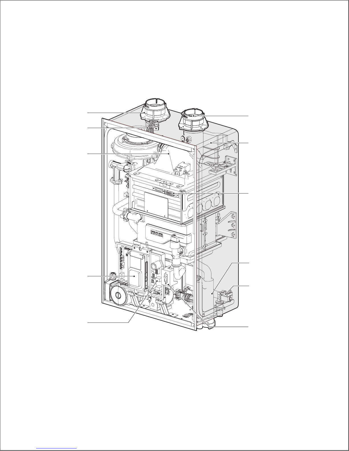
2.2 Components
The following diagram shows the key components of the boiler. Component assembly diagrams and particular parts lists are included in the
Appendixes.
Intake Air
Exhaust
Flue Duct
Igniter & Flame Rod
Condensate Trap
Auto Feeder
(Make-up water)
Power Switch
Air Filter
Mixing
Chamber
Front Panel
PCB
Version 1.4
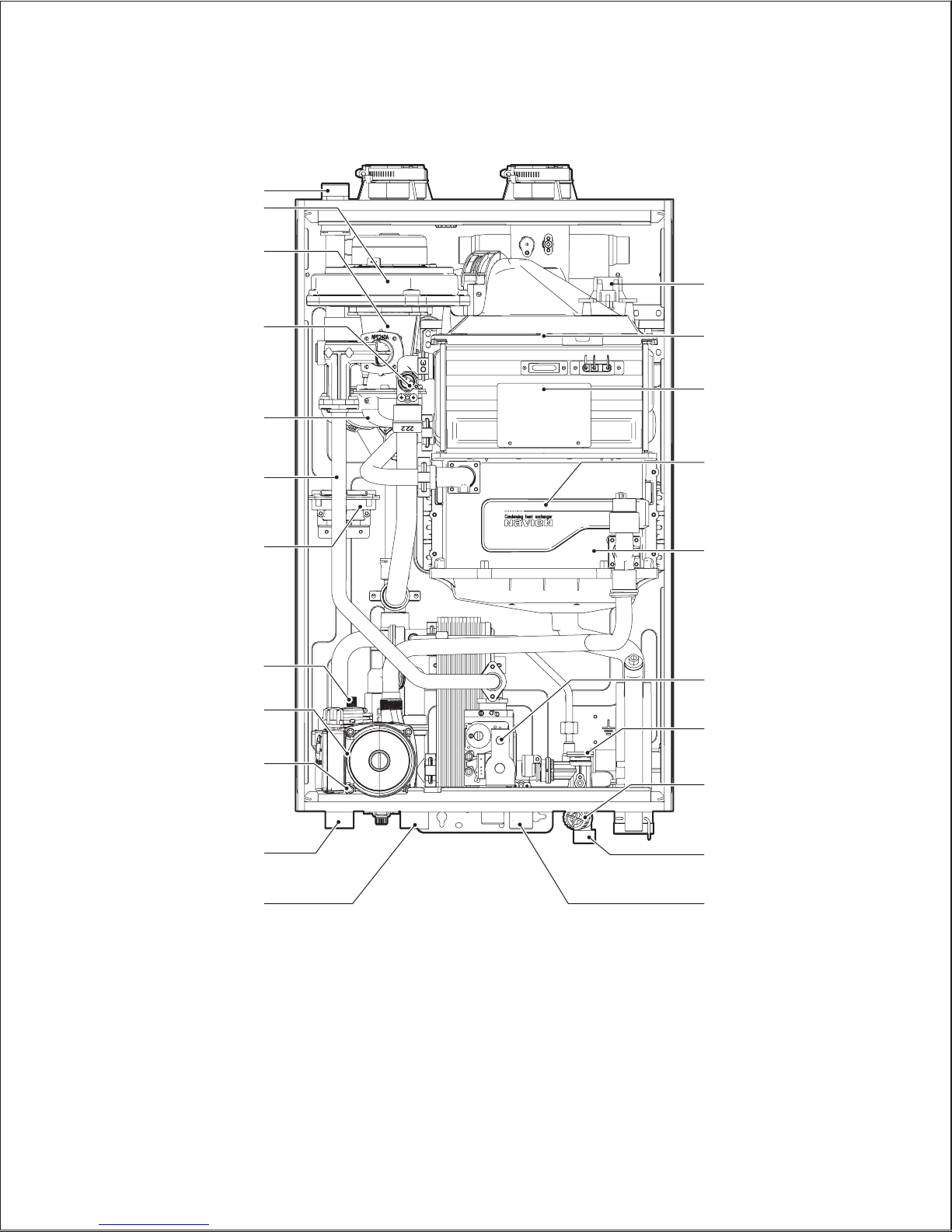
16 NCB-E Service Manual
Pressure Relief Valve Adapter
Fan & Motor
Dual Venturi
High Limit Switch
Air Pipe
Gas Pipe
APS
Air Vent
Circulation Pump
3-Way Valve
Space Heating Supply
Space Heating Return
Ignition Transformer
Premix Burner
Primary Heat Exchanger
Secondary Heat
Exchanger
Pressure Sensor
(LWCO)
Gas Valve
Flow Sensor
DHW Inlet Filter
(with built-in flow
restrictor)
DHW Inlet
DHW Outlet
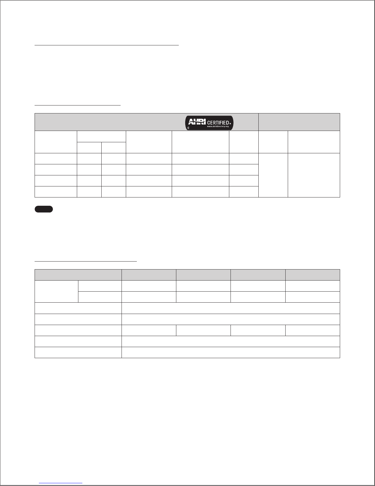
Technical Data 17
3.1 General Specifications
The following table lists the specifications for the boiler. Additional specifications about water, gas, electric, and air supplies (venting) appear in
the Installation section.
Space Heating Specifications
Navien Combination Boiler
Space Heating Ratings
Other Specifications
Model Number
1
Heating Input, MBH
Heating Capacity
2
,
MBH
Net AHRI Rating Water3,
MBH
AFUE
2
, %
Water
Pressure
Water Connection
size (Supply, Return)
Min Max
NCB-150E 12 60 56 49 95
12-30 psi 1 in NPT
NCB-180E 14 80 75 65 95
NCB-210E 18 100 94 82 95
NCB-240E 18 120 112 97 95
Note
1. Ratings are the same for natural gas models converted to propane use.
2. Based on U.S. Department of Energy (DOE) test procedures.
3. The net AHRI water ratings shown are based on a piping and pickup allowance of 1.15. Consult Navien before selecting a
boiler for installations having unusual piping and pickup requirements, such as intermittent system operation, extensive piping
system, etc.
Domestic Hot Water Specifications
Item NCB-150E NCB-180E NCB-210E NCB-240E
Input Ratings
Min 12,000 BTU/H 14,000 BTU/H 18,000 BTU/H 18,000 BTU/H
Max 120,000 BTU/H 150,000 BTU/H 180,000 BTU/H 199,900 BTU/H
Water Pressure 15-150 psi
Minimum Flow Rate 0.5 GPM (1.9 L/m)
Flow Rate 77°F (43°C) Temp. Rise 3.1 GPM 3.4 GPM 4.0 GPM 4.5 GPM
DHW Supply Connection Size
3
/4 in NPT
Cold Water Input Connection Size
3
/4 in NPT
3. Technical Data
Version 1.4
18 NCB-E Service Manual
General Specifications
Item NCB-150E NCB-180E NCB-210E NCB-240E
Dimensions 17 in (W) x 28 in (H) x 12 in (D)
Weight 66 lbs (30 kg) 74 lbs (34 kg) 84 lbs (38 kg) 84 lbs (38 kg)
Installation Type Indoor Wall-Hung
Venting Type Forced Draft Direct Vent
Ignition Electronic Ignition
Natural Gas Supply Pressure (from source) 3.5 in-10.5 in WC
Propane Gas Supply Pressure (from source) 8.0 in-13.5 in WC
Natural Gas Manifold Pressure (min/max)
-0.09 in WC /
-0.34 in WC
-0.07 in WC /
-0.66 in WC
-0.05 in WC /
-0.36 in WC
-0.06 in WC /
-1.20 in WC
Propane Gas Manifold Pressure (min/max)
-0.04 in WC /
-0.30 in WC
-0.07 in WC /
-0.66 in WC
-0.10 in WC /
-0.66 in WC
-0.03 in WC /
-0.98 in WC
Gas Connection Size
3
/4 in NPT
Power Supply
Main Supply 120V AC, 60Hz
Maximum Power
Consumption
200W (max 2A)
Materials
Casing Cold-rolled carbon steel
Heat Exchangers
Primary Heat Exchanger: Stainless Steel
Secondary Heat Exchanger: Stainless Steel
Domestic Water Heat Exchanger: Stainless Steel
Venting
Exhaust
2 in or 3 in PVC, CPVC, Polypropylene
2 in or 3 in Special Gas Vent Type BH (Class III, A/B/C)
Intake
2 in or 3 in PVC, CPVC, Polypropylene
2 in or 3 in Special Gas Vent Type BH (Class III, A/B/C)
Vent Clearances 0 in to combustibles
Safety Devices
Flame Rod, APS, Gas Valve Operation Detector, Ignition Operation Detector, Water
Temperature High Limit Switch,
Exhaust Temperature High Limit Sensor
NOTE
This unit may be installed at elevations up to 10,100 ft (3,078 m) for use with Natural Gas, and up to 4,500 ft (1,370 m) for use with Propane.
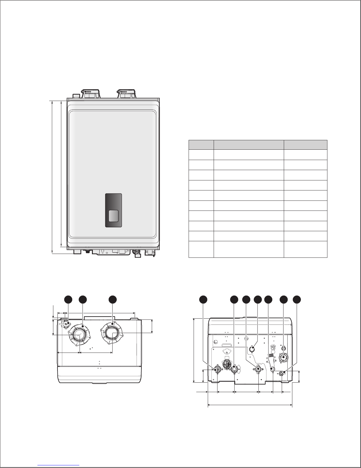
Technical Data 19
3.2 Dimensions
The following diagrams show the dimensions of the boiler and the table lists the supply connections.
27.4" (695mm)
28.8” (731mm)
Supply Connections
Description Diameter
A Pressure Relief Valve Adapter
3
/4 in
B Air Intake 2 in
C Exhaust Gas Vent 2 in
D Space Heating Supply 1 in
E Space Heating Return 1 in
F Hot Water Outlet (DHW)
3
/4 in
G Gas Supply Inlet
3
/4 in
H Cold Water Inlet (DHW)
3
/4 in
I Condensate Outlet
1
/2 in
J
Auto Feeder Inlet (Make-up
Water)
1
/2 in
Overhead View
3” (77 mm)
6.7” (170 mm)
4.5” (115 mm)
0.4“ (10 mm)
1.5”
(38 mm)
14.3” (364 mm)
2.6” (67 mm)
A
B C
Supply Connections
12“ (306 mm)
3.5”
(88 mm)
4.8”
(123 mm)3”(76 mm)
1.8”
(46 mm)
2”
(50 mm)
17.3” (440 mm)
2.4” (61 mm)
3.0” (77 mm)
D F J
E
H
IG
Version 1.4
20 NCB-E Service Manual
4.1 Setting the DIP Switches
CAUTION
Do not remove the front cover unless the power to the
boiler is turned off or disconnected. Failure to do so may
result in electric shock.
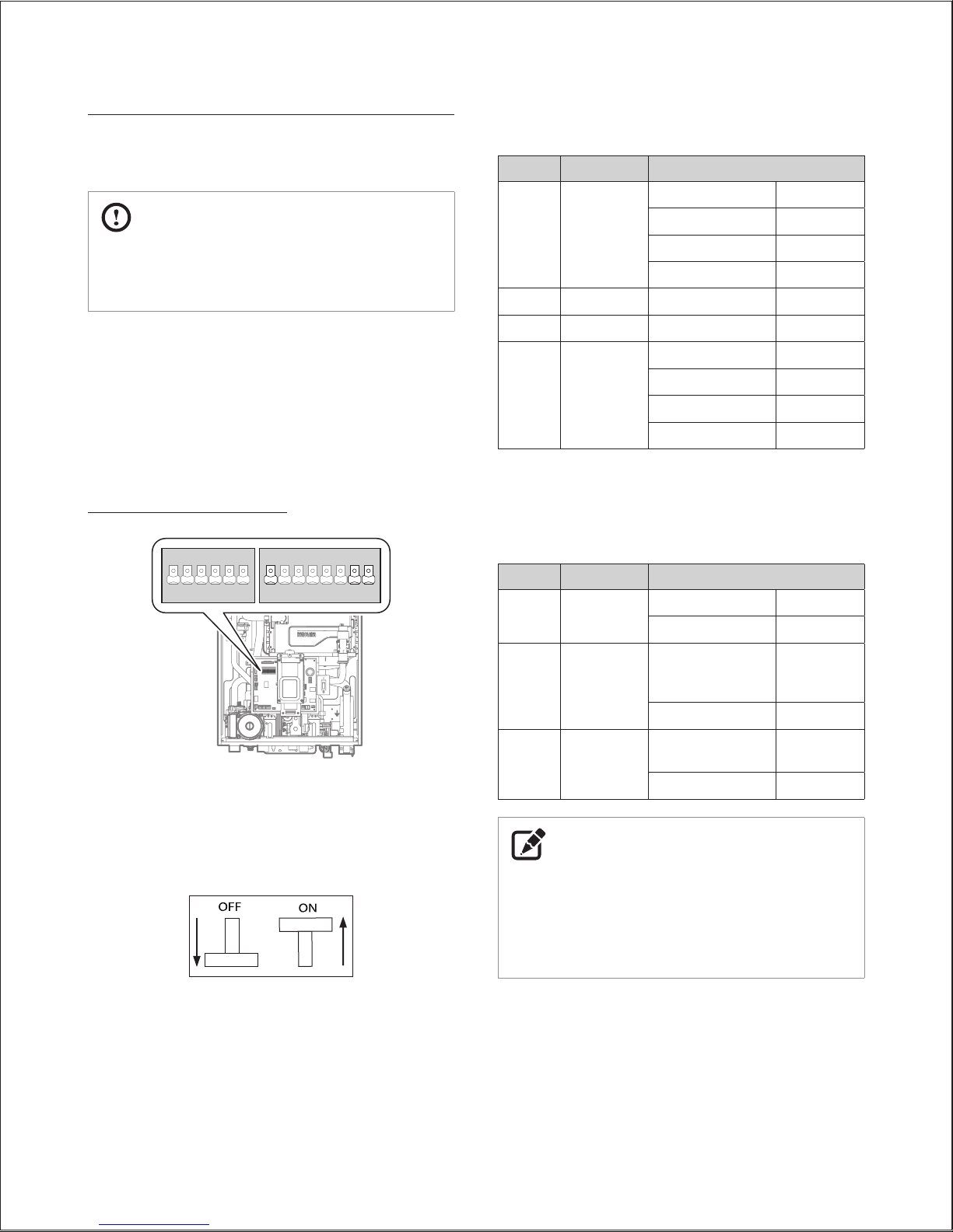
The boiler has two DIP switch locations: on the main circuit board
(PCB) and on the front panel. Each location has two sets of DIP
switches that control the functionality of the boiler. Set the DIP
switches appropriately, based on the installation environment and
the gas type.
4.1.1 Setting the DIP Switches
Circuit Board DIP Switches
1 2 3 4 5 6ON1 2 3 4 5 6 7 8
ON
●
Set of DIP Switches 1 (Set of 6)
The DIP switches 1 on the circuit board configure the boiler’s
model and gas type settings. These configurations are set at the
factory and should not be changed. The following tables describe
the functions of the DIP switches and their settings.
Ex) DIP Switch On/Off
Switch Function Setting
1 & 2
Operation
Status
Normal 1-OFF, 2-OFF
Forced Max (2 stage) 1-ON, 2-OFF
Forced Min (1 stage) 1-OFF, 2-ON
1 Stage Max 1-ON, 2-ON
3 Reserved - -
4 Reserved - -
5 & 6
Capacity
select
NCB-150E 5-ON, 6-ON
NCB-180E 5-OFF, 6-OFF
NCB-210E 5-ON, 6-OFF
NCB-240E 5-OFF, 6-ON
●
Set of DIP Switches 2 (Set of 8)
The DIP SW 2 on the circuit board configures additional features at
the time of installation, such as temperature control modes.
Switch Function Setting
1
Temperature
Control
Return Water 1-ON
Supply Water 1-OFF
7
Thermostat
or Zone
Controller
Unused (Permanent
space heating
demand)
7-ON
Used 7-OFF
8
Exhaust
Thermostat
Temperature Limit
Unused (CPVC)
8-ON
Setting (PVC) 8-OFF
NOTE
●
When PCB DIP switch #8 on DIP switches 2(set of 8), the
boiler does not operate without an exhaust thermostat
installed.
●
When you set PCB switch #8 on DIP switches 2(set of 8) to on,
ensure that CPVC piping is used for exhaust venting.
4. System Details
System Details 21
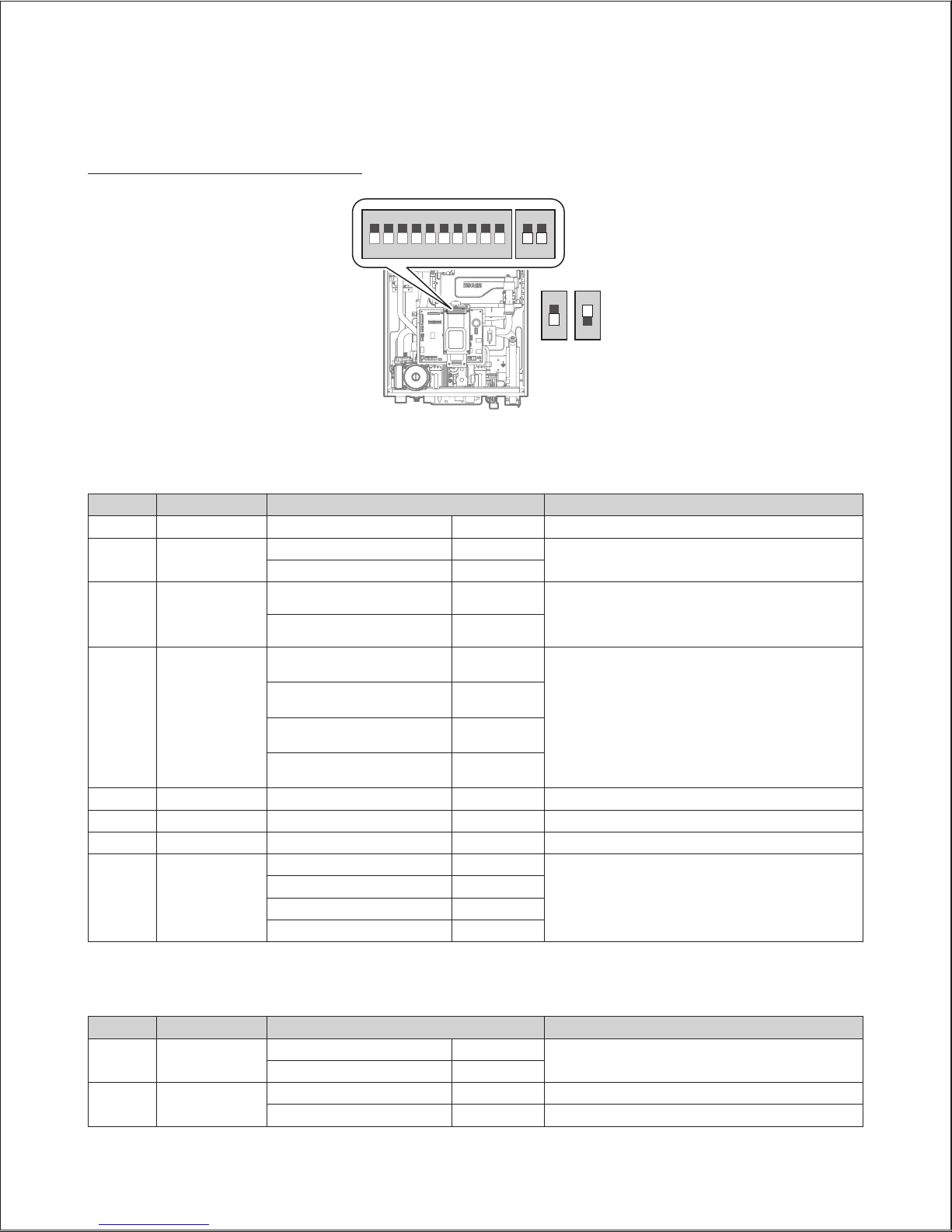
Setting the Front Panel DIP Switches
1 2 3 4 5 6 7 8 9 10
1 2
ON ON
2
ON
NG LP
2
ON
●
Set of DIP Switches 1 (Set of 10)
The DIP SW 1 on the front panel configures the temperature unit, well pump, and high altitude settings.
SW1 NO. Application Setting Remarks
1 Reserve
2 Temperature Unit
°C (Celsius) 2-ON
°F (Fahrenheit) 2-OFF
3 Well Pump
Well Pump ON 3-ON Well Pump Mode
These settings are to be used with well system when an
external pump is wired to the boiler.Well Pump OFF 3-OFF
4 & 5 High Altitude
0-1,999 ft (0-609 m) 4-OFF, 5-OFF
High Altitude
Above 2,000 ft (610 m), the boiler will de-rate by 4% for
each 1,000 ft (305 m) of altitude gain.
This boiler may be installed at elevations up to 10,100
ft (3,078 m) for use with Natural Gas and 4,500 ft (1,370
m) for use with Propane. To use the boiler at a specific
altitude, the DIP switches should be set as described
above.
2,000-5,399 ft (610-1,645 m) 4-ON, 5-OFF
5,400-7,699 ft (1,646-2,346 m) 4-OFF, 5-ON
7,700-10,100 ft (2,347-3,078 m) 4-ON, 5-ON
6 Reserve
7 Reserve
8 Reserve
9 & 10 Lime Alarm
Off 9-OFF, 10-OFF
Cascade system only
(Front Panel: after V1.2)
6 Months Alert 9-ON, 10-OFF
12 Months Alert 9-OFF, 10-ON
12 Months Alert 9-ON, 10-ON
●
Set of DIP Switches 2 (Set of 2)
The DIP SW 2 on the front panel configures the gas type setting.
SW1 NO. Application Setting Remarks
1 Cascade vent
Common Vent 1-OFF
Cascade system only
(Front Panel: after V1.2)
Individual Vent 1-ON
2 Gas type
Natural Gas 2-OFF
Propane Gas 2-ON
Version 1.4
22 NCB-E Service Manual
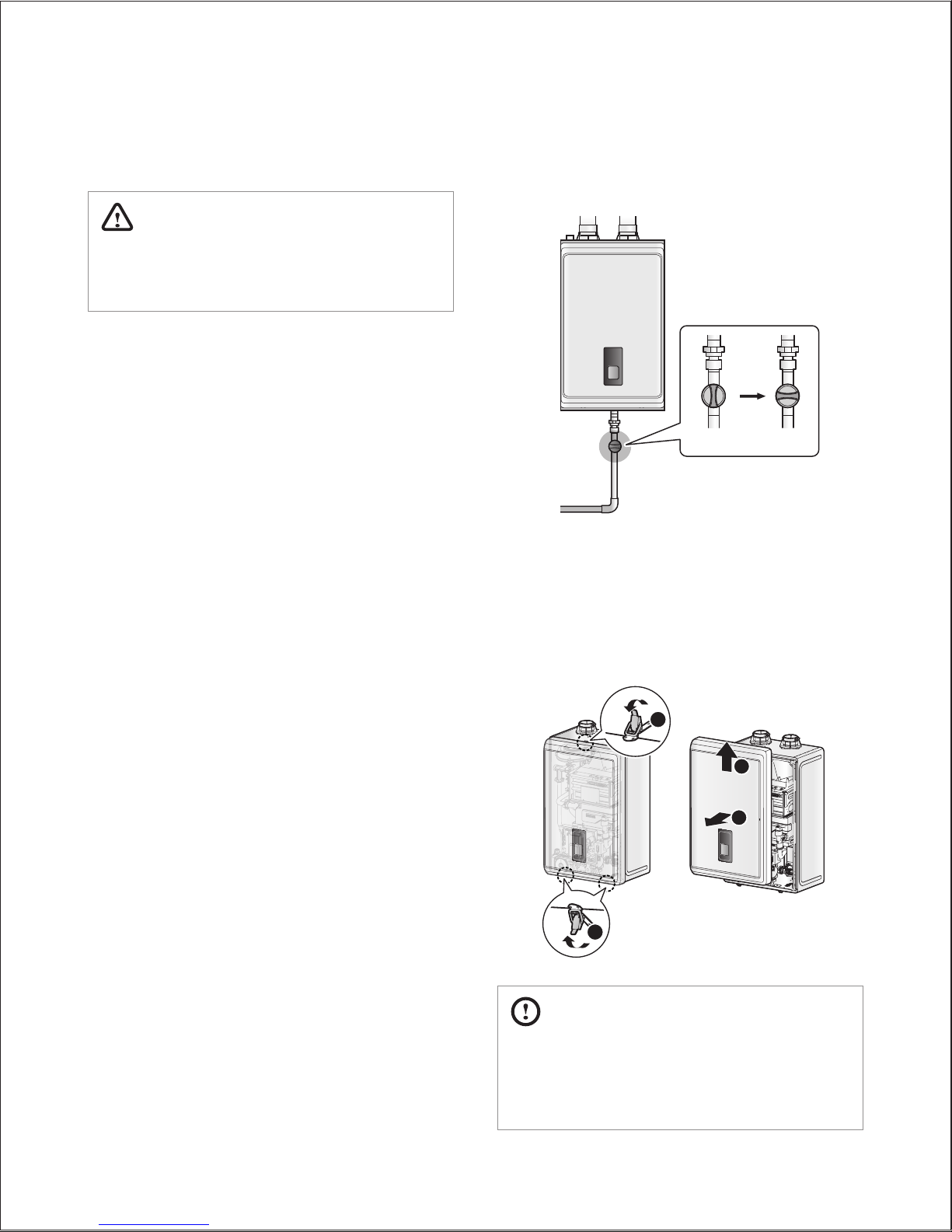
To measure the inlet gas pressure:
1. Shut off the manual gas valve on the gas supply line.
Gas Valve
Opened Closed
2. Open a hot water faucet. The boiler should turn on and the gas
in the gas supply line will be purged.
3. Leave the faucet on until the boiler shuts down due to a lack of
gas supply, and then turn off the hot water faucet.
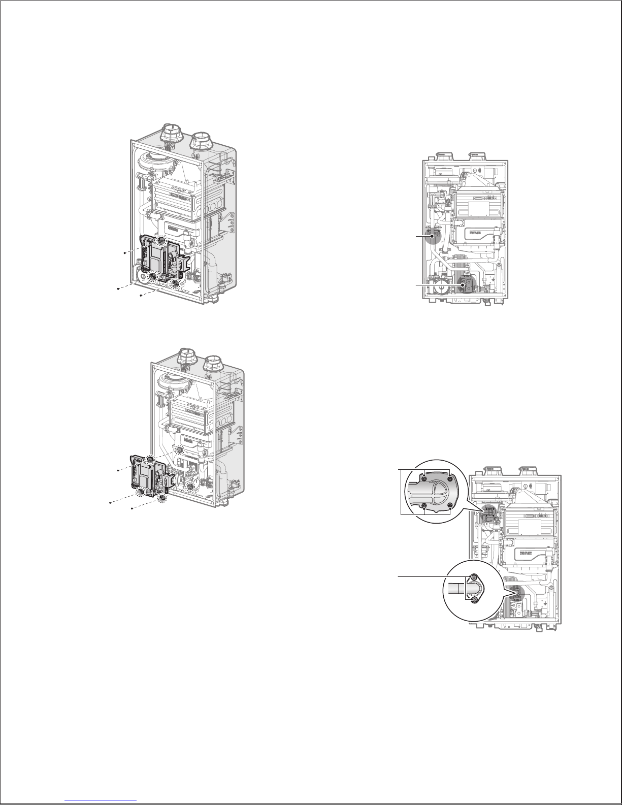
4. Unclasp the 3 buckles that fix the cover to the boiler, and then
remove the cover by lifting it and pulling it outward.
1
1
2
3
CAUTION
Ensure that no cables are in the way before folding down the
PCB assembly. If the assembly is stuck, do not force it. Doing
so may damage the cables and result in serious malfunctions.
Check again to ensure that no cables or any other parts are in
the way before you proceed.
4.2 Measuring the Inlet Gas Pressure
WARNING
The boiler cannot function properly without sufficient inlet
gas pressure. Measuring the inlet gas pressure should be
performed by a licensed professional only.
●
The inlet gas pressure must be maintained between 3.5” and
10.5” WC for natural gas and between 8.0” and 13.5” WC for
liquefied propane.
●
The appliance and its individual shutoff valve must be
disconnected from the gas supply piping system during any
pressure testing of that system at test pressures in excess of
1/2 psi (3.5 kPa).
●
The appliance must be isolated from the gas supply piping
system by closing its individual manual shutoff valve during
any pressure testing of the gas supply piping system at test
pressures equal to or less than 1/2 psi (3.5 kPa).
System Details 23
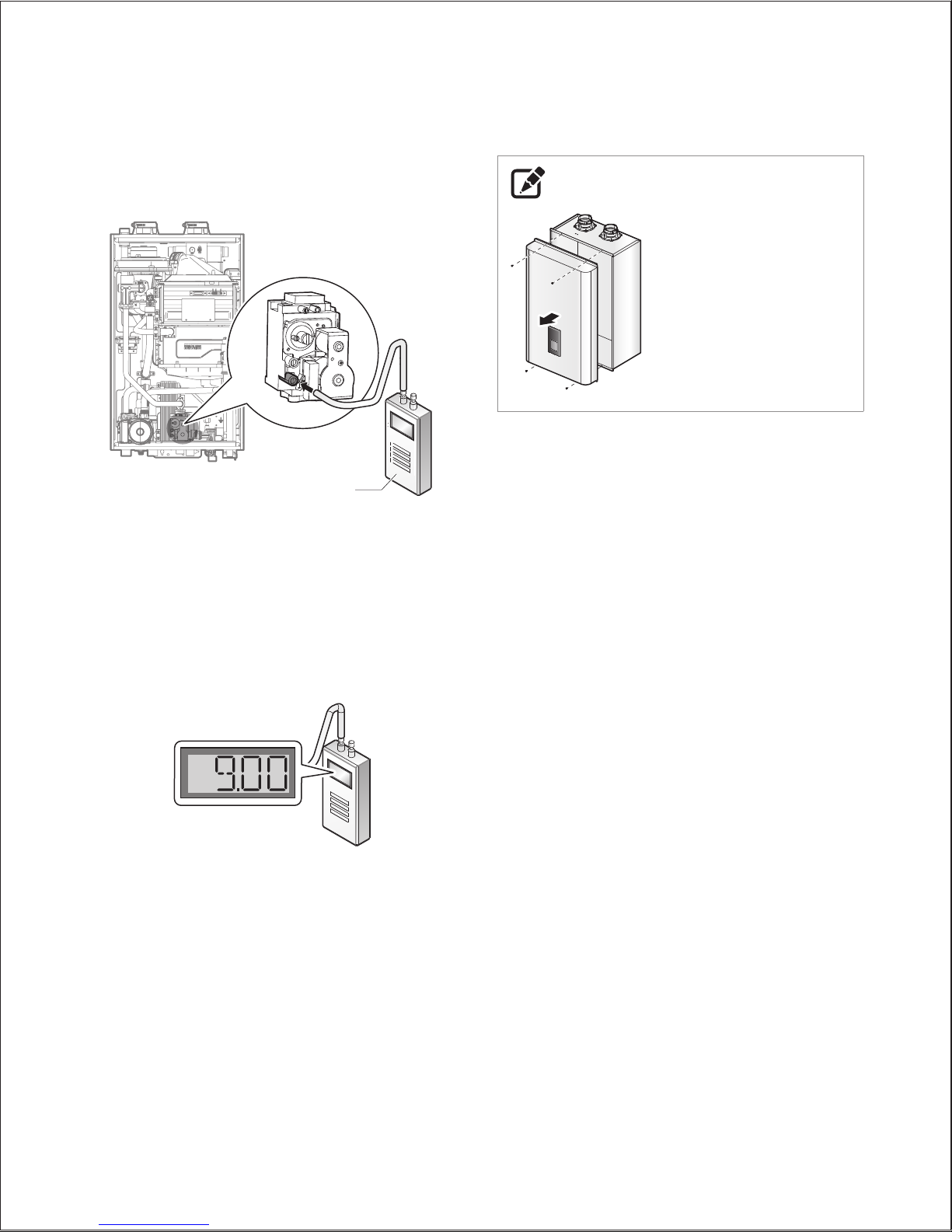
NOTE
For NCB series, remove
the boiler front cover by
loosening the 4 Phillips head
screws securing it to the
case.
5. Loosen the screws indicated in the figure below and connect a
manometer to the pressure port. Reset the manometer to zero
before use.
Digital pressure
manometer
6. Re-open the manual gas valve and check for leaks.
7. Open multiple fixtures that have high flow rates, such as
bathtub and shower faucets, to ramp the boiler up to its
maximum firing rate.
8. When the boiler reaches its maximum firing rate, check the
inlet gas pressure reading on the manometer. The gas pressure
must fall within the ranges specified on page 18.

Version 1.4
24 NCB-E Service Manual
4.2.1 Gas Pipe Sizing Tables (Referenced from 2012 National Fuel Gas Code)
These tables are for reference only. Please consult the gas pipe manufacturer for actual pipe capacities.
Maximum Natural Gas Delivery Capacity
in Cubic Feet (ft3) per Hour (0.60 Specific Gravity; 0.5” WC Pressure Drop). Contact your gas supplier for BTU/ft3 ratings. Use 1,000 BTU/ft3 for
simplified calculations. This table is recommended for supply pressures less than 6” WC.
Pipe Size
Length (including fittings)
10'
(3m)
20'
(6m)
30'
(9m)
40'
(12m)
50'
(15m)
60'
(18m)
70'
(21m)
80'
(24m)
90'
(27m)
100'
(30m)
125'
(38m)
3/4" 360 247 199 170 151 137 126 117 110 104 92
1" 678 466 374 320 284 257 237 220 207 195 173
1 1/4" 1,390 957 768 657 583 528 486 452 424 400 355
1 1/2" 2,090 1,430 1,150 985 873 791 728 677 635 600 532
2" 4,020 2,760 2,220 1,900 1,680 1,520 1,400 1,300 1,220 1,160 1,020
2 1/2" 6,400 4,400 3,530 3,020 2,680 2,430 2,230 2,080 1,950 1,840 1,630
3" 11,300 7,780 6,250 5,350 4,740 4,290 3,950 3,670 3,450 3,260 2,890
4" 23,100 15,900 12,700 10,900 9,660 8,760 8,050 7,490 7,030 6,640 5,890
in Cubic Feet (ft
3
) per Hour (0.60 Specific Gravity; 3.0” WC Pressure Drop). Contact your gas supplier for BTU/ft3 ratings. Use 1,000 BTU/ft3 for
simplified calculations. This table is recommended for supply pressures of 6” WC or greater.
Pipe Size
Length (including fittings)
10'
(3m)
20'
(6m)
30'
(9m)
40'
(12m)
50'
(15m)
60'
(18m)
70'
(21m)
80'
(24m)
90'
(27m)
100'
(30m)
125'
(38m)
1/2" 454 312 250 214 190 172 158 147 138 131 116
3/4" 949 652 524 448 397 360 331 308 289 273 242
1" 1,787 1,228 986 844 748 678 624 580 544 514 456
1 1/4" 3,669 2,522 2,025 1,733 1,536 1,392 1,280 1,191 1,118 1,056 936
1 1/2" 5,497 3,778 3,034 2,597 2,302 2,085 1,919 1,785 1,675 1,582 1,402
2" 10,588 7,277 5,844 5,001 4,433 4,016 3,695 3,437 3,225 3,046 2,700
2 1/2" 16,875 11,598 9,314 7,971 7,065 6,401 5,889 5,479 5,140 4,856 4,303
3" 29,832 20,503 16,465 14,092 12,489 11,316 10,411 9,685 9,087 8,584 7,608
4" 43,678 30,020 24,107 20,632 18,286 16,569 15,243 14,181 13,305 12,568 11,139
System Details 25
Maximum Liquefied Propane Delivery Capacity
in Thousands of BTU/H (0.5” WC Pressure Drop)
Pipe Size
Length (including fittings)
10'
(3m)
20'
(6m)
30'
(9m)
40'
(12m)
50'
(15m)
60'
(18m)
80'
(24m)
100'
(30m)
125'
(38m)
150'
(45m)
175'
(53m)
200'
(60m)
250'
(76m)
1/2" 291 200 160 137 122 110 101 94 89 84 74 67 62
3/4" 608 418 336 287 255 231 212 197 185 175 155 140 129
1" 1,150 787 632 541 480 434 400 372 349 330 292 265 243
1 1/4" 2,350 1,620 1,300 1,110 985 892 821 763 716 677 600 543 500
1 1/2" 3,520 2,420 1,940 1,660 1,480 1,340 1,230 1,140 1,070 1,010 899 814 749
2" 6,790 4,660 3,750 3,210 2,840 2,570 2,370 2,200 2,070 1,950 1,730 1,570 1,440
NOTE
●
For installations using CSST (flexible) gas piping, please refer to the sizing charts provided by the manufacturer.
●
The use of single-stage regulators are recommended. Dual-stage regulators could cause operational issues with the boiler.
Version 1.4
26 NCB-E Service Manual
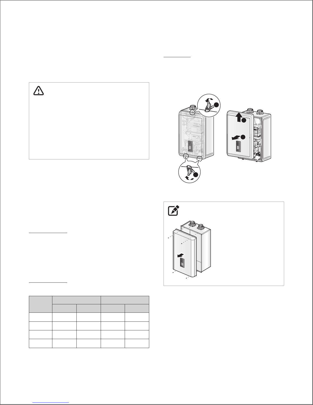
Procedure:
1. Turn off both gas and water supply to the boiler.
2. Unclasp the 3 buckles that fix the cover to the boiler, and then
remove the cover by lifting it and pulling it outward. See Figure
1 for illustration of the front cover on the unit.
1
1
2
3
Figure 1. NCB-E Series Front cover
NOTE
For NCB series, remove
the boiler front cover by
loosening the 4 Phillips head
screws securing it to the
case.
3. Once the front cover is removed, place it in a safe location to
prevent accidental damage.
4. Label all the wires on the PCB.
5. Disconnect all the wires.
4.3 Gas Conversion
This boiler is configured for Natural Gas from the factory. If
conversion to Propane Gas is required, the conversion kit supplied
with the boiler must be used.
WARNING
This conversion kit shall be installed by a qualified service
agency* in accordance with Navien’s instructions and all
applicable codes and requirements of the authority having
jurisdiction. The information in these instructions must be
followed to minimize the risk of fire or explosion or to prevent
property damage, personal injury or death. The qualified
service agency is responsible for the proper installation of
this kit. The installation is not proper and complete until the
operation of the converted appliance is checked as specified in
the manufacturer’s instructions supplied with the kit.
* A qualified service agency is any individual, firm, corporation or company
which either in person or through a representative is engaged in and
is responsible for the connection, utilization, repair or servicing of gas
utilization equipment or accessories; who is experienced in such work,
familiar with all precautions required, and has complied with all of the
requirements of the authority having jurisdiction.
In Canada: The conversion shall be carried out in accordance with
the requirements of the provincial authorities having jurisdiction
and in accordance with the requirements of the CAN‐B149.1 and
CAN1‐B149.2 Installation Code.
Tools Required:
●
Phillips Screwdriver
●
Flathead Screwdriver
●
5
/32 in or 4mm Allen Wrench
●
Combustion Analyzer or Dual Port Manometer
●
Gas Leak Detector
Included Items:
●
Gas Orifice (refer to below table)
Model
NG LP
1STAGE 2STAGE 1STAGE 2STAGE
NCB-150E Ø5.10 Ø5.80 Ø4.10 Ø4.50
NCB-180E Ø4.80 Ø5.95 Ø3.80 Ø4.70
NCB-210E Ø6.10 Ø6.30 Ø4.50 Ø4.80
NCB-240E Ø6.10 Ø6.30 Ø4.50 Ø4.80
Table 1. Orifice Size
●
Gas Pressure and Conversion Kit Number Labels
System Details 27
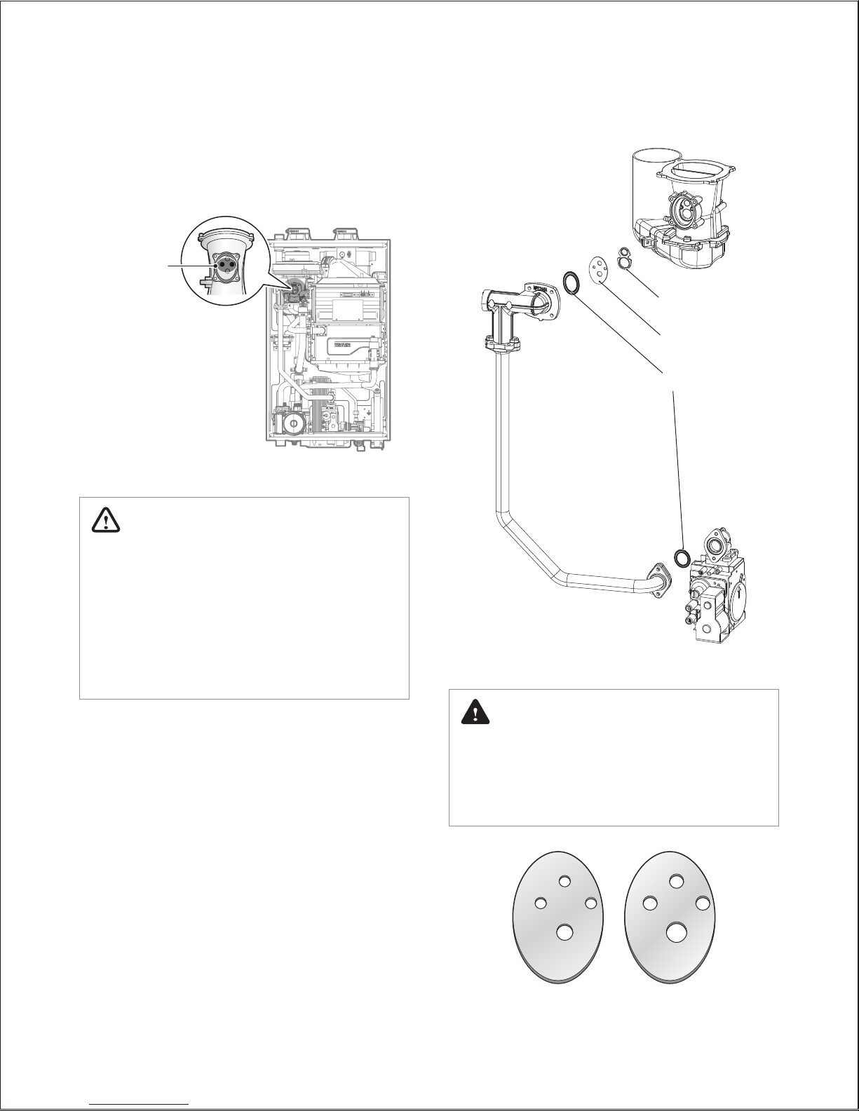
8. With the internal components exposed, locate the gas inlet
pipe and the gas valve in the middle of the unit, as shown in
Figure 2.
Gas Valve
Gas Inlet
Pipe
Figure 2. NCB-E Series Internal Components
9. Use a Phillips screwdriver to remove the two screws at location
A - the connection below the gas valve where it connects
to the pipe. See Figure 3 for reference. Once the screws are
removed, carefully separate the pipe from the gas valve.
10. Once the gas inlet pipe is detached from the gas valve, find
location B - the connection above the gas valve where it is
attached to the fan motor assembly. Carefully remove the four
screws by hand using a Phillips screwdriver and pull the gas
valve away from the fan assembly to access the gas orifice.
Location B: Remove
4 screws here
Location A: Remove
2 screws here
Figure 3. Detaching Gas Valve from
Gas Inlet Pipe and Fan Motor Assembly
6. Loosen the three screws indicated in the figure.
7. Remove the PCB assembly.
Version 1.4
28 NCB-E Service Manual
O-ring
Gas Orifice
Packing
Figure 5. Exploded View of Gas Pipe Assembly
DANGER
See Figure 5. Inspect the O-ring between the gas valve and
gas valve inlet adapter whenever they are disassembled.
The O-ring must be in good condition and must be installed.
Failure to comply will cause a gas leak, resulting in severe
personal injury or death.
240LP 240NG
Figure 6. Orifice Identification
11. Once the Gas Orifice is exposed, remove the two screws that
hold the part in place. Remove the Gas Orifice from its housing
and prepare the new Gas Orifice for the LP conversion for
installation.
Remove two
2 screws here
Figure 4. Access to Gas Orifice in Fan Assembly
WARNING
●
DO NOT adjust or attempt to measure gas valve outlet
pressure. The gas valve is factory-set for the correct outlet
pressure. This setting is suitable for natural gas and propane,
requiring no field adjustment.
●
Attempting to alter or measure the gas valve outlet pressure
could result in damage to the valve, causing potential severe
personal injury, death or substantial property damage.
Navien NCB-E boilers are shipped ready to fire natural gas
ONLY.
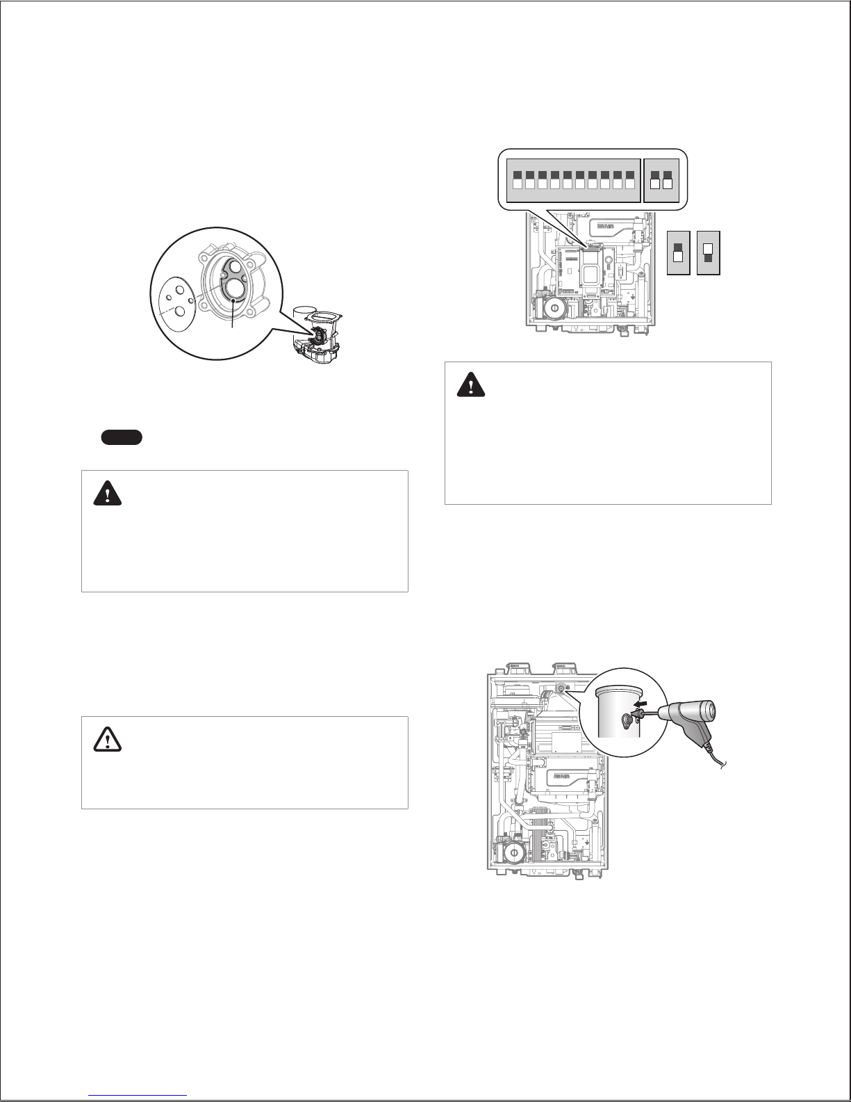
System Details 29
12. Remove the Gas Orifice, ensure that the packing is properly
seated inside the port, and then install the new Gas Orifice for
use with LP gas. Ensure that the Orifice is properly seated on
the packing inside the port before proceeding to the next step.
Packing
13. Replace the gas inlet pipe to its original position and use all
screws to secure all connections.
Note
Do not overtighten as this may damage or crack
the components.
DANGER
Inspect the O-ring between the gas valve and gas valve inlet
adapter whenever they are disassembled. The O-ring must be
in good condition and must be installed. Failure to comply will
cause a gas leak, resulting in severe personal injury or death.
14. Place the PCB assembly back on to the boiler and tighten the
three screws.
15. Check the labels carefully and then connect all the wires.
16. Set the front panel Dip Switch to change the gas type. For LP,
set Dip Switch 2 #2 to On. For NG, set DIP SW2 #2 to Off.
WARNING
Ensure that you have turned off the power to the boiler before
accessing the DIP switches.
1 2 3 4 5 6 7 8 9 10
1 2
ON ON
2
ON
NG LP
2
ON
DANGER
●
When conversion is required, be sure to set the front panel
DIP switches according to the supply gas type.
●
Failure to properly set the DIP switches could cause carbon
monoxide poisoning, resulting in severe personal injury or
death.
17. Turn on the gas and water supply to the boiler.
18. Measure and adjust the gas/air ratio.
Option 1. Using Combustion Analyzer (recommended)
a. Loosen the screw, rotate the plate and remove the gasket
to access the emissions monitoring port as shown in
Figure 7.
b. Insert the analyzer into the port (Figure 7).
Figure 7. Insert the Analyzer
 Loading...