

Navien NCB-180NCB-210, NCB-210, NCB-240 Quick Installation Manual
Quick Installation Guide
Model
NCB-180/210/240
1
STEP 1 Before Installing
Read the Installation & Operation Manual before installing.
This product must be installed and serviced by a licensed
plumber, a licensed gas fitter, or a professional service
technician. Navien is not liable for any damages or
defects
resulting from improper installation.
Whe
n applicable, the in stallation must conform with
Manufactured Home Construction and Safety Standard, Title 24 CFR, Part 3280
and/or CAN/CSA Z240 MH Series, Mobile Homes.
Safety
DO NOT install the boiler in areas with excessively high humidity.
Location Requirements
Select the best location on “Choosing an Installation” in the Installation &
Operation Manual.
Allowable minimum clearances
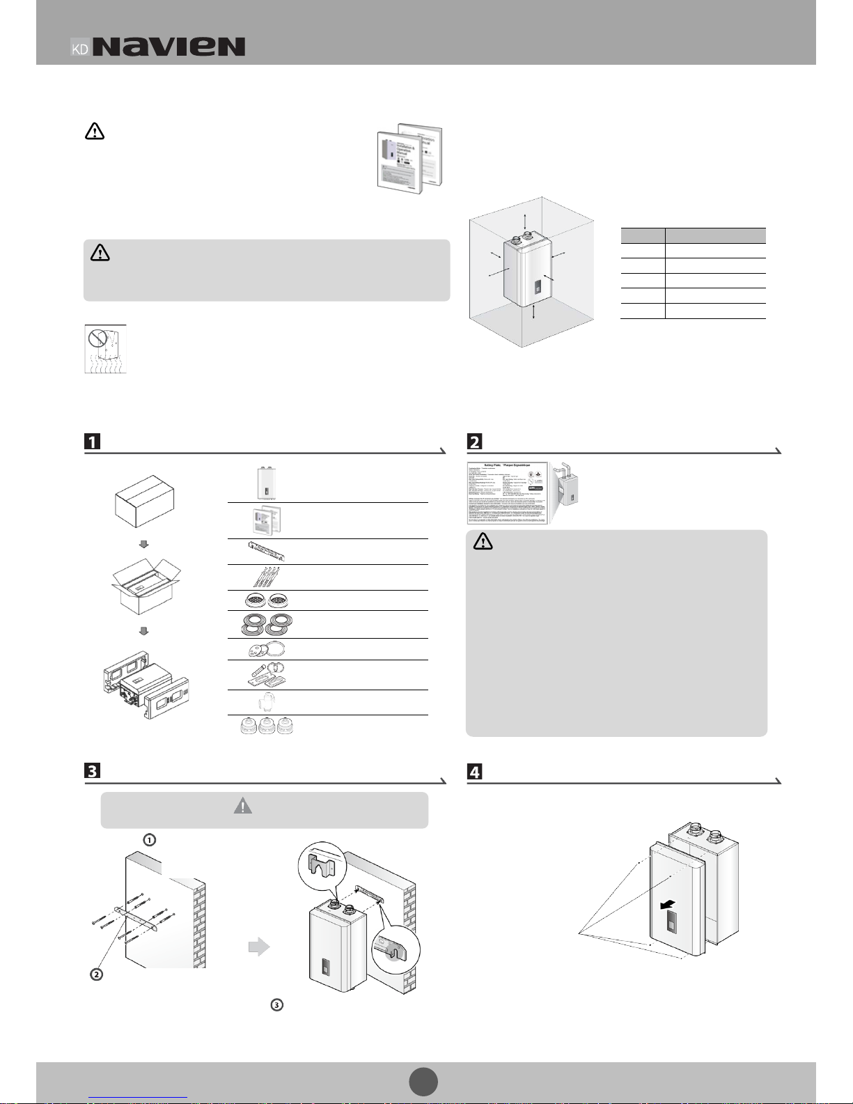
STEP 2 Installing
Unpacking
Checking the Rating Plate
This boiler is configured for Natural Gas
from the factory. If conversion to Propane
Gas in required, the conversion kit supplied
with
the boiler must be used.
Mounting on the Wall
Removing the Front Cover
Remove the
4 screws
Lift up the boiler, rest the unit on the
hooks provided on the wall bracket
on the wall.
Secure the mounting bracket
to the wall with the tapping
screws and anchors.
Drill in the supplied anchor
bolts after considering where
the vent term
ination will be
located.
CAUTION
Do not install the boiler on dry walls without proper reinforcement.
WARNING
• Before connecting the gas supply, determine the gas type and
pressure for the boiler by referr ing to the rating plate. Use only the
same gas type indicated on the rating plate. Using a different gas
type will result in abnormal combustion an d malfunction of the
boiler. Gas supplies should be connected by a licensed professional
on ly.
• The appliance and its gas connection must be leak tested before
placing the appliance in operation.
• This boiler cannot be converted from natural gas to propane or vice
versa without a Navien gas conversion kit. Do not attempt a field
conversion of this boiler without a Navien gas conversion kit. Doing
so will result in dangerous operating conditions and will void the
warranty.
Navien America Inc. is not liable for any property damage and/or
personal injury resulting from improper conversions.
Navien Combination Boiler
User’s Information Manual,
Installation & Operation Manual
Wall mounting bracket
Tapping screws and anchors
Vent terminators
Wall flanges
Conversion Kit
Spare Parts
Pressure Relief Valve (30PSI)
Flow Restrictors
Clearance
Indoor Installation
Top
9 in (229 mm) minimum
Back
0.5 in (13 mm) minimum
Front
4 in (100 mm) minimum
Sides
3 in (76 mm) minimum
Bottom
12 in (300 mm) minimum
Top
Back
Side
Side
Front
Bottom
WARNING
Follow all local codes and/or the most recent edition of the National Fuel Gas Code
(ANSI Z223.1/NFPA 54) in the USA, or the Natural Gas and Propane Installation Code in
Canada (CAN/CGA B149.1).
2
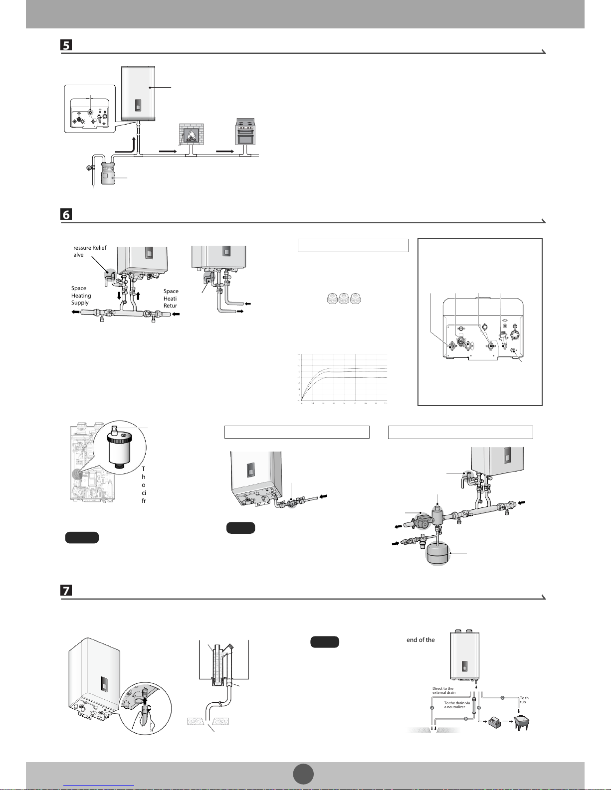
Gas Piping Connections
Water Piping Connections
Condensate Drain Connection
A condensate drain pipe must be connected to the 1/2” condensate outlet fitting at
the bottom of the unit and water must be poured into the exhaust connection to fill
the condensate trap.
The end of the 1/2” (NPT) plastic piping should drain into a laundry tub or into a floor
drain.
Do not submerge the end of the
pipe in water.
Note
Syphon
Condensate Outlet
Water
Floor drain
The
boiler is recommended to be the first
appliance to be connected
to the gas supply
line.
Gas meter’s capacity ≥ Total gas capacity of connected appliances
Gas supply
Gas
Regulator
Bottom View
Gas Inlet Adapter
Gas Supply Line
Example:
Gas meter
425 CFH
≥
Boiler
195 CFH
+
Furn ace
58.8 CFH
+
Domestic gas stove
63.7CFH
* 1 C
FH=1,020 Btuh
•
1/2" rigid pipe can be used; refer to the sizing tables in the Installation &
Operation Manual for limitations. Avoid using 1/2" corrugated connectors
or tubing as noise may occur.
Built-in Water Fill Connection
Navien NCB boiler is equipped with
an auto
-feeding water connection
and motorized feeding valve.
Therefore, installation of additional
system water fill connection is not
necessary in most cases.
Note
Backflow
Preventer
Make-up
Water
External Water Fill Connection
Heating
Supply
Expansion Tank
Circul ator
Pressure Relief Valve
Air Separator
Warning
Water Piping Connections
Space Heating System
DHW System
Install the included 3/4 in, maximum 30
psi pressure relief valve on the space
heating
supply.
An ASM
E approved HV pressure relief
valve for space heating system is
supplied with the boiler
.
The DHW pressure relief valve is
not supplied, but is req uired.
I
nstall an approved 3/4 in,
maximum 150 psi pressure relief
valve on the hot water
outlet.
Space
H
eating
Return
Space
Heating
Supply
Pressure Relief
Valve
Pressure
Relief
Valve
Cold Water
Supply
DHW
Supply
Space
Heating
Supply
Space
Heating
Return
DHW
Supply
Cold
Water
Inlet
Built-in
Water Feeder
Connection
Flow Restrictor (for DHW system)
Flow R ate (GPM) and Water Pressure (psi)
Orange
Yellow
Blue
The boiler has a built-in flow restrictor at
the cold water inlet adapter to limit the
overall
DHW flo w. Three additional flow
restrictors
are provided for different flow
rates.
Refer to the following graph and install
an appropriate restrictor for your DHW
system.
See the Installation & Operation
Manual (page 21, 22) for detailed
procedure s.
Flow Restrictors (Orange, Yellow, and Blue)
Ensure that the Air Vent Cap is removed
before fillin
g the sys tem.
System will not be properly filled
without the air vent cap removed. Air in
the system may cause malfunctions
and system overheating.
Make
-up
Water
Direct to the
external drain
To the drain via
a neutralizer
External drain
To the laundry
tub
To the laundry tub
via a condensate pump
System Fill Connection
The Navien NCB boilers
have a built
-in air vent
on top of the internal
circulator to purge air
from the boiler system.
Air Vent Cap
Before filling the boiler, remove the air vent cap to
allow the s
ystem to fill properly. Replace the cap
when the system is full.
Heating
Return
 Loading...