

Navien NCB-20LHWE, NCB-23LHWE, NCB-28LHWE, NCB-33LHWE Operation Manual
These appliances are for use with natural gas or LPG.
(An LPG conversion kit is included with the boiler.)
Type : B23-B33-B53-C13-C33-C43-C53-C63-C83
Installation &
Operation
Manual
Keep this manual near this boiler for future reference
whenever maintenance or service is required.
WARNING
result, causing property damage or personal injury.
–
other appliance.
–
WHAT TO DO IF YOU SMELL GAS
Do not try to light any appliances.
Do not touch any electrical switch; do not use any phone in your building.
Immediately call the National Gas Emergency Helpline on (Freephone) 0800 111999 or your gas
supplier from a neighbour’s phone. Follow the instructions received.
–
Installation and service must be performed by a Gas Safe registered installer, service agency or
the gas supplier.
Condensing System Boiler
Gas Model GC Number
Natural Gas
NCB-20LHWE
NCB-23LHWE
NCB-28LHWE
NCB-33LHWE
41-709-01
41-709-02
41-709-03
41-709-04
LPG
NCB-20LHWE
NCB-23LHWE
NCB-28LHWE
NCB-33LHWE
41-709-05
41-709-06
41-709-07
41-709-08

Contents
1. Safety Information 3
2. About the Boiler
7
2.1 Items Included 7
2.2 Accessories
7
2.3 Technical Data
8
2.4 Components
11
2.5 Dimensions
15
2.6 Operating Modes
16
2.7 Installation Procedure
17
3. Installing the Boiler 18
3.1 Choosing an Installation Location 18
3.2 Mounting the Boiler to the Wall
20
4. Installing the System Piping 21
4.1 Installing a Space Heating System 21
4.2 Installing a System Application
22
4.3 Connecting the Condensate Drain Line
22
4.4 Pressure Relief Valve
24
4.5 Filling the system
24
4.6 Testing the Water System
24
5. Connecting the Gas Supply 25
5.1 Gas Pipe Material 26
5.2 Propane Gas Installations (LPG)
26
5.3 Measuring the Inlet Gas Pressure
26
6. Flue System 28
6.1 Flue Terminal Positions 28
6.2 Selecting a Flue System
29
6.3 Coaxi
al Systems
30
6.4 Dual Duct Systems
31
6.5 Measuring Flue Length
33
6.6 Terminating the Flue
33
7. Setting the DIP Switches 34
7.1 PCB DIP Switches 34
7.2 Front Panel DIP Switches
34
8. Connecting Electrical Supplies 35
8.1 Accessing the Terminal Blocks 35
8.2 Connecting the Power Supply Cables
36
8.3 Setting the DIP Switches and Parameters for the
Terminal blocks 1 and 2
37
8.4 Terminal block 1 Connection
37
8.5 Terminal block 2 Connection
38
9. Wiring Examples for Dierent Applications 39
9.1 Connecting the Navien Smart Room Controller
(Optional)
39
9.2 Y Plan Applications
40
9.3 S Plan Applications 43
10. Installation Check list 44
11. Operating the Boiler
45
11.1 Turning the Boiler On or O 45
11.2 Adjusting the Temperature
45
11.3 Viewing Basic Information
46
11.4 Setting the Operation Mode
47
11.5 Setting the Parameters
48
11.6 Resetting the Boiler
55
12. Maintaining the Boiler 56
12.1 Cleaning the Boiler 56
12.2 Draining the Bo
iler 56
12.3 Cleaning the Return Adapter Filter
57
12.4 Protecting the Boiler from Freezing
57
12.5 Maintenance Schedules
58
13. Appendices 61
13.1 Gas Conversion 61
13.2 Cleaning the Heat Exchanger
67
13.3 Wiring Diagram
70
13.4 Ladder Diagram
71
13.5 Outdoor Temperature Sensor (Optional)
72
2 Contents
The following safety symbols are used in this manual. Read and
follow all safety instructions in this manual precisely to avoid
unsafe operating conditions, re, explosion, property damage or
personal injury.
DANGER
Indicates an imminently hazardous
situation which, if not avoided, could
result in severe injury or death.
WARNING
Indicates a potentially hazardous
situation which, if not avoided, could
result in injury or death.
CAUTION
Indicates a potentially hazardous
situation which, if not avoided, could
result in property damage.
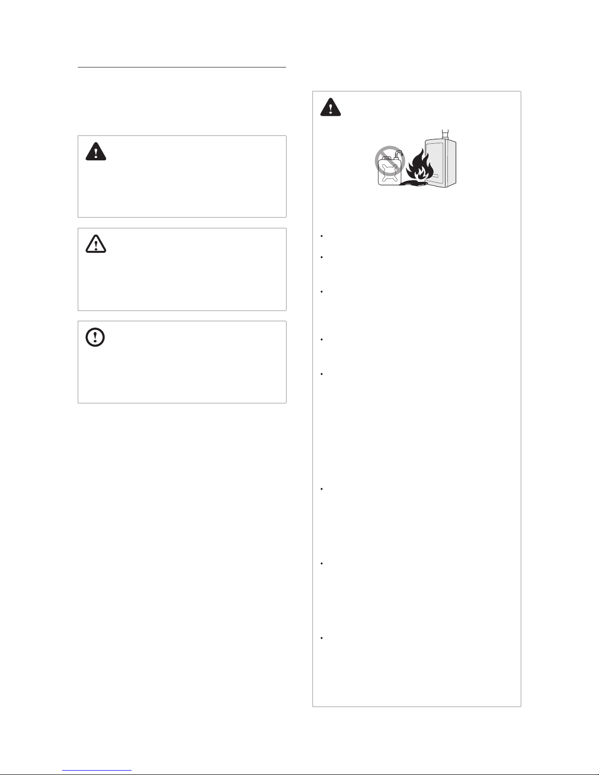
DANGER
If you smell gas:
Do not try to light any appliances.
Do not touch any electrical switches or
use landline phones.
From a neighbour’s phone, call
your gas provider and follow their
instructions.
If you cannot reach your gas provider,
call the re department.
Do not return to your home until
authorised by your gas supplier or the
re department.
Do not use or store ammable
products, such as petrol, solvents, or
adhesives in the same room or area as
the boiler.
The boiler has a main burner ame that
can turn on at any time and can ignite
ammable vapours. Vapours from
ammable liquids can explode and
catch re, causing severe burns.
Vapours cannot be seen and are
heavier than air. They can travel long
distances along the ground and can be
carried from other rooms to the boiler’s
main burner ame by air current.
Keep all ammable products far
away from the boiler and store them
in approved containers. Keep the
containers closed tightly and out of the
reach of children and pets.
1. Safety Information
3Safety Information
4 Safety Information
WARNING
This appliance can be used by children
aged from 8 years and above and
persons with reduced physical, sensory
or mental capabilities or lack of
experience and knowledge if they have
been given supervision or instruction
concerning use of the appliance in a
safe way and understand the hazards
involved. Children shall not play with
the appliance. Cleaning and user
maintenance shall not be made by
children without supervision.
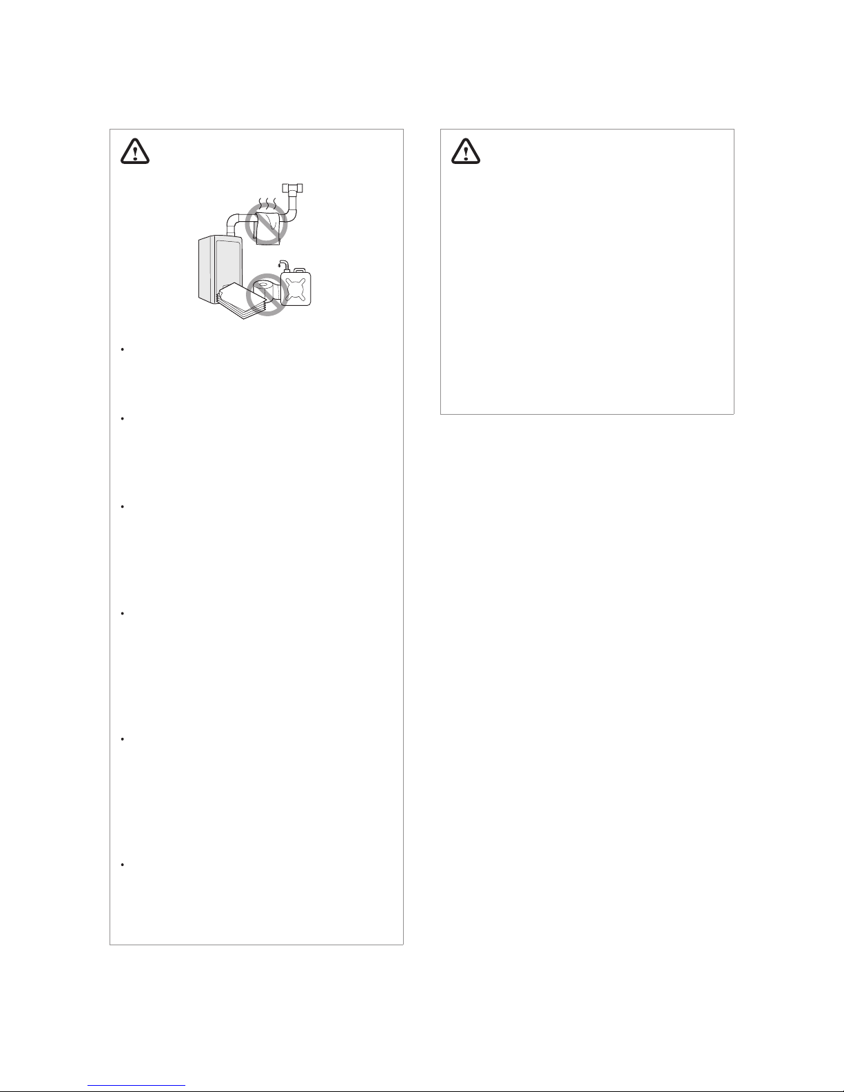
WARNING
Do not store or use petrol or other
ammable liquids near this boiler.
Doing so may result in re or explosion.
Do not place combustibles, such as
newspapers or laundry, near the
boiler or ue system.
Doing so may result in a re.
Do not place or use hair sprays, spray
paints, or any other compressed
gases near the boiler or ue system,
including the ue termination.
Doing so may result in re or explosion.
Do not operate the boiler with the
front cover opened.
Doing so may result in re or carbon
monoxide (CO) poisoning, which may
result in property damage or personal
injury.
Do not operate this boiler without
proper ue system.
Doing so may result in re or carbon
monoxide (CO) poisoning, which may
result in property damage or personal
injury.
Do not touch the power cord or
internal components of the boiler
with wet hands.
Doing so may result in electric shock.
5Safety Information
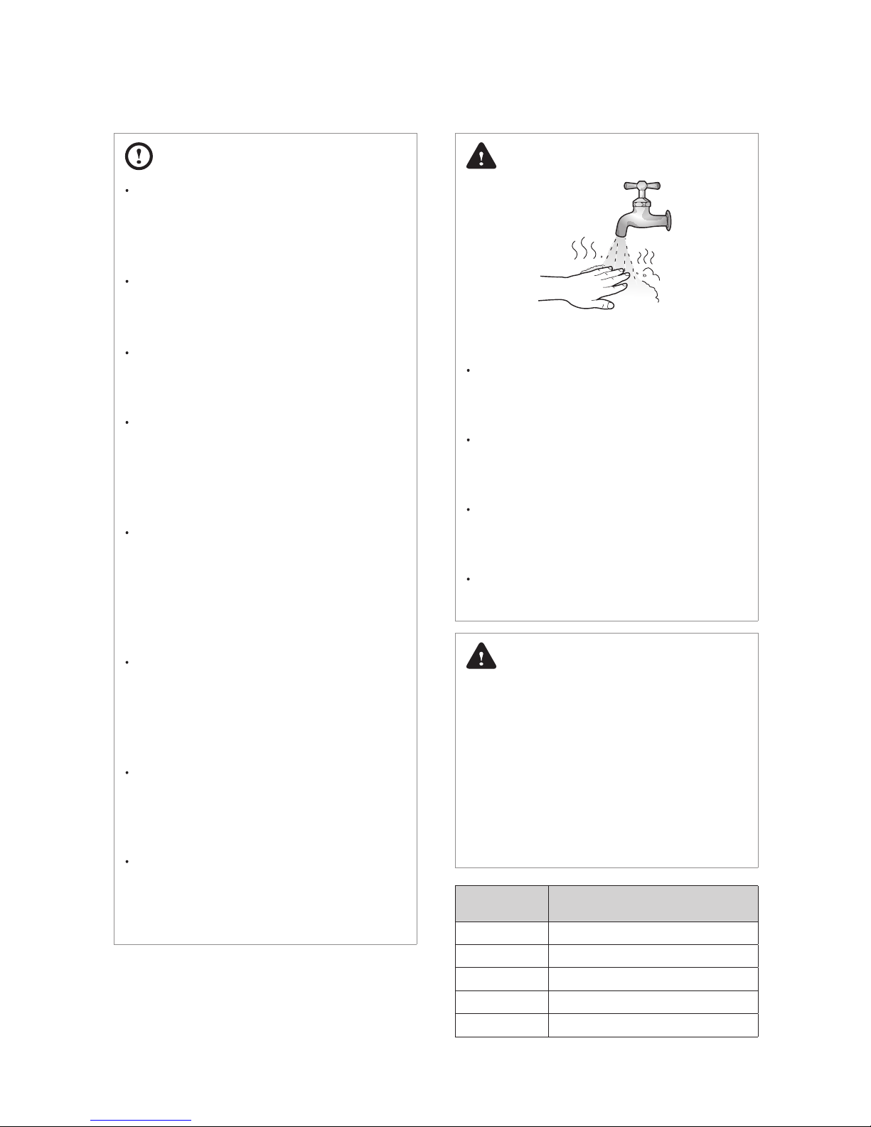
DANGER
HOT
BURN
To prevent burns:
Use the lowest operating temperature
setting necessary to provide
comfortably hot water.
If your household has children or
elderly or disabled residents, consider
using a lower temperature setting.
Read all the instructions in this
manual carefully before changing the
temperature setting.
Feel the water before using it on
children, the elderly, or the disabled.
DANGER
This boiler’s water temperature is set to
49°C at the factory for your safety and
comfort. Increasing the temperature
increases the risk of accidental scalding.
Water temperatures at or above 52°C
can cause instant scalding or severe
burns. Before you decide to change the
temperature setting, read the following
charts carefully.
Water
Temperature
Time in which a young child can suer a
full thickness (3rd degree) burn
70°C Less than 1 second
60°C 1 second
55°C 10 seconds
49°C 10 minutes
37°C Very low scald risk
CAUTION
Do not turn on the boiler unless
the water and gas supplies are fully
opened.
Doing so may damage the boiler.
Do not turn on the water if the cold
water supply shut-o valve is closed.
Doing so may damage the boiler.
Do not use this boiler for anything
other than its intended purpose, as
described in this manual.
Do not remove the front cover unless
the power to the boiler is turned o
or disconnected.
Failure to do so may result in electric
shock.
When servicing the controls, label all
wires prior to disconnecting them.
Failure to do so may result in wiring
errors, which can lead to improper or
dangerous operation. Verify proper
operation after servicing.
Do not use unapproved replacement
or accessory parts.
Doing so may result in improper or
dangerous operation and will void the
manufacturer’s warranty.
Do not place anything in or around
the ue terminals, such as a clothes
line, that could obstruct the air ow
in or out of the boiler.
This boiler has been approved for
use the UK and Ireland only.
Using the boiler in any other country
will void the manufacturer’s warranty.
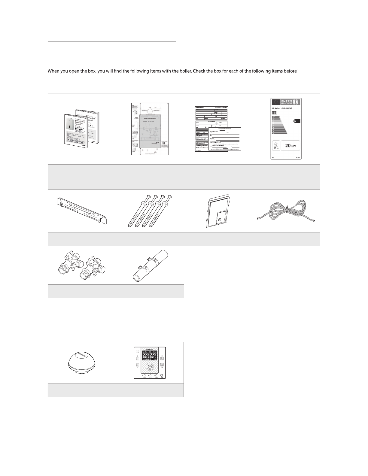
2.1 Items Included
nstalling
the boiler. If it seems like there is a problem, do not use the boiler. Contact your supplier. Keep the included items out of the reach of
children, as they can be dangerous. When you no longer wish to use the boiler, disable any parts that could be potentially hazardous.
Installation & Operation
Manual, User’s Information
Manual
Boiler mounting plate
Boiler registration / Installers
Club Card
ErP Label
Wall mounting bracket Tapping screws & anchors Propane gas changing kit Electric cord
Pre-plumbing Kit Condensate trap hose
2.2 Accessories
The following optional accessories are available for the boiler:
Outdoor Temperature Sensor Smart Room Controller
2. About the Boiler
6 Safety Information
General Installation Guidelines
Navien ensures that this product contains no harmful
substances and that no harmful materials have been used in its
manufacture.
Current legislation must be taken into account on installing
this appliance, and it must be installed in a place with suitable
ventilation.
The boiler must be installed by an installer authorised by the
Ministry of Industry and it must be started up by an Ocial
Technical Assistance Service authorised by Navien.
The requirements included in the following regulations must be
observed on installing the boiler:
- The Gas Installation Regulation.
- The Technical Building Code.
- The Regulation for Heating Installations in Building.
- The Low Voltage Regulation.
Installing the system piping
The boiler is equipped with an internal relief valve. All systems
must be capable of sustaining pressure of up to 3 bar.
If the system pressure exceeds 2.65 bar at the maximum
heating temperature, an additional expansion vessel must be
installed on the central heating return.
The air vent is required in the system during lling.
CAUTION
The boiler is equipped with an internal
bypass valve. The internal bypass valve
is not intended to replace an external
bypass valve. An external automatic
bypass valve is required if a zone valve
has been connected to the system.
Gas Conversion
The boiler is congured for natural gas. If LPG conversion is
required, use the conversion kit supplied with the boiler.
The Codes of good practice and regulations refer to the
latest versions of the same.
The installation must also comply with the following European
Standards:
Standard Description
UNE-EN 13831:2008
Closed expansion vessels with
diaphragm.
UNE-EN 1856 Metal chimneys
UNE-EN 13384 Chimneys
UNE-EN 13779 Ventilation
UNE-EN ISO 16484 Building control systems.
UNE-EN 14336 Heating systems in buildings.
UNE-EN 15502-1
Gas-red heating boilers
Part 1: General Requirements and tests
UNE-EN 15502-2-1
Gas-red heating boilers
Part 2-1: Specic standard for type
C appliances and type B2, B3 and B5
appliances of a nominal heat input not
exceeding 1000 kW
UNE-EN 13203:2007 Domestic Hot Water
UNE-EN 303-7:2008 Heating boilers.
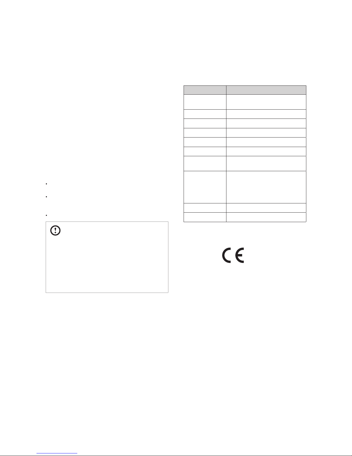
EC Conformity Declaration
0063
Navien, hereby declares that the boiler models:
NCB-20LHWE, NCB-23LHWE, NCB-28LHWE, NCB-33LHWE
to which this declaration refers, conform to and comply with
the essential requirements of the following applicable European
Standards and Directives.
Gas appliances dna 734 NE sdradnatS CE/241/9002 evitceriD :
EN 15502
Boiler Eciency: Directives 92/42/EEC and
93/68/EEC
Regulation (EN) No. 813/2013
Standards EN 15502
Low voltage: Directives 73/23/EEC and
93/68/EEC Standard EN 60335-1, EN 60335-2-30,
EN 60335-2-51, EN 50165
Electro-magnetic Compatibility: Directive 2004/108/EC
Standards EN 55014
Pressure Vessels: Directive 97/23/EEC
Navien, manufactures its products using a Quality Assurance
system in compliance with Standard EN-ISO 9001:2000.
2.1 Items Included
nstalling
the boiler. If it seems like there is a problem, do not use the boiler. Contact your supplier. Keep the included items out of the reach of
children, as they can be dangerous. When you no longer wish to use the boiler, disable any parts that could be potentially hazardous.
Installation & Operation
Manual, User’s Information
Manual
Boiler mounting plate
Boiler registration / Installers
Club Card
ErP Label
Wall mounting bracket Tapping screws & anchors Propane gas changing kit Electric cord
Pre-plumbing Kit Condensate trap hose
2.2 Accessories
The following optional accessories are available for the boiler:
Outdoor Temperature Sensor Smart Room Controller
2. About the Boiler
7About the Boiler
8
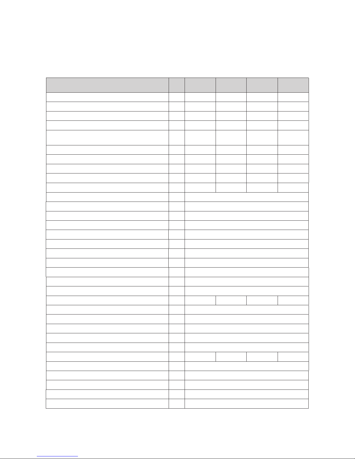
2.3 Technical Data
The following table lists the general specications for the boiler.
Specications Unit
NCB-
20LHWE
NCB-
23LHWE
NCB-
28LHWE
NCB-
33LHWE
Heat input range kW 20.0/4.2 24.0/4.2 29.0/5.1 34.0/4.0
Heat output range @ 80/60°C kW 19.5/3.9 23.4/3.9 28.3/4.9 33.2/3.8
Condensing heat output range @ 50/30°C kW 21.4/4.5 25.6/4.5 31.1/5.4 36.3/4.3
Full load eciency at Max./Min. output @ 80/60°C % 97.5/96.4 97.5/96.4 97.6/96.4 97.6/95.8
Full load eciency at Max./Min. output @ 50/30°C
(Condensing)
% 106.9/107.8 106.6/107.8 107.3/106.9 106.9/106.9
Partial load (30%) eciency with 47°C return temp. % 101.9 103.1 102.0 103.1
Partial load (30%) eciency with 30°C return temp. % 108.6 108.9 108.5 108.8
Heat loss through the case with burner switched on % 0.1 0.1 0.1 0.1
Heat loss through the chimney with burner switched on % 1.6 1.8 1.5 1.9
Seasonal eciency rate (SEDBUK 2009) - 89.0 89.1 89.0 89.1
NOx Classication - Class 5
Category - II2H3P
Type - Heating and instantaneous hot water production
Heat output adjustmen
t - Adjustable over entire Max./Min. output range
Type of heating installation - Close circuit
Max. heating operation pressure bar 2.5
Max. heating temperature °C 90
Adjustable heating temperature range °C 40-90
Expansion vessel volume l 6.0
Expansion vessel pre-charged pressure bar 1.0
Electrical power supply - 230 V/50 Hz
Nominal current A 0.6 0.6 0.62 0.62
Max. power consumption W 130
Appliance protection rating - IP X5D
Boiler mounting system type - Wall-mounted
Flue exhaust/Air intake system types - B23-B33-B53-C13-C33-C43-C53-C63-C83
Flue exhaust/Air intake system diameters mm Coaxial Ø60/100 and Ø80/125–Dual duct Ø80/80
Max. gas pipe pressure drop Pa 167 167 294 294
Max. horizontal coaxial length Ø60/100 m 20
Max. vertical coaxial length Ø60/100 m 21
Equivalent elbow length @ 90° Ø60/100 m 1.3
Equivalent elbow length @ 45° Ø60/100 m
1.0
Max. horizontal coaxial length Ø80/125 m 68
Unit
NCB-
20LHWE
NCB-
23LHWE
NCB-
28LHWE
NCB-
33LHWE
Max. vertical coaxial length Ø80/125 m 70
Equivalent elbow length @ 90° Ø80/125 m 2.2
Equivalent elbow length @ 45° Ø80/125 m 1.0
Equivalent length of adapter Ø60/100 => Ø80/125 m 0.5
Max. dual duct length Ø80/80 m 110
Equivalent elbow length @ 90° Ø80 m 2.2
Equivalent elbow length @ 45° Ø80 m 1.4
Hydraulic connection
diameter
Central Heating mm 22
DHW mm 15
Gas supply mm 22
Dimensions (Width x Depth x Height) mm 440 x 358 x 695 440 x 408 x 695
Total boiler weight (lift weight) Kg 36 36 40 40
About the Boiler
Unit
NCB-
20LHWE
NCB-
23LHWE
NCB-
28LHWE
NCB-
33LHWE
Max. vertical coaxial length Ø80/125 m 70
Equivalent elbow length @ 90° Ø80/125 m 2.2
Equivalent elbow length @ 45° Ø80/125 m 1.0
Equivalent length of adapter Ø60/100 => Ø80/125 m 0.5
Max. dual duct length Ø80/80 m 110
Equivalent elbow length @ 90° Ø80 m 2.2
Equivalent elbow length @ 45° Ø80 m 1.4
Hydraulic connection
diameter
Central Heating mm 22
DHW mm 15
Gas supply mm 22
Dimensions (Width x Depth x Height) mm 440 x 358 x 695 440 x 408 x 695
Total boiler weight (lift weight) Kg 36 36 40 40
9About the Boiler
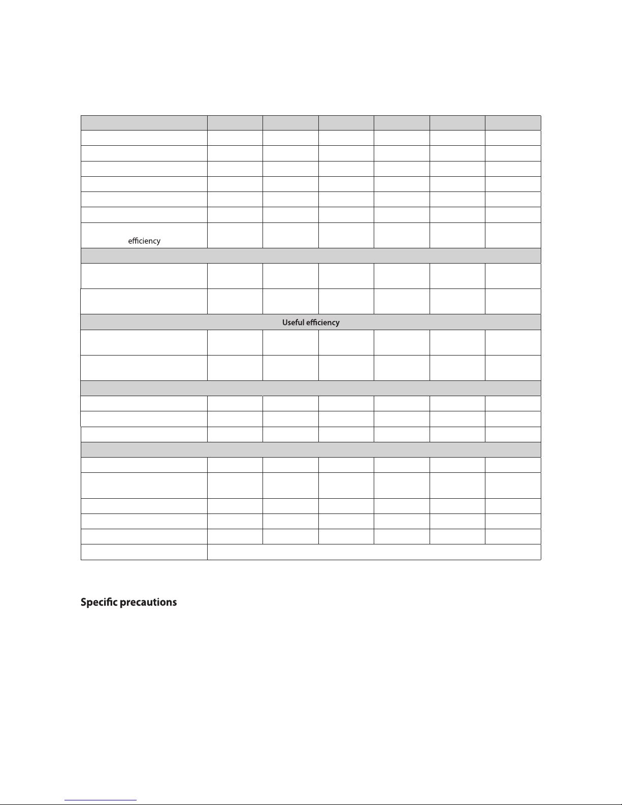
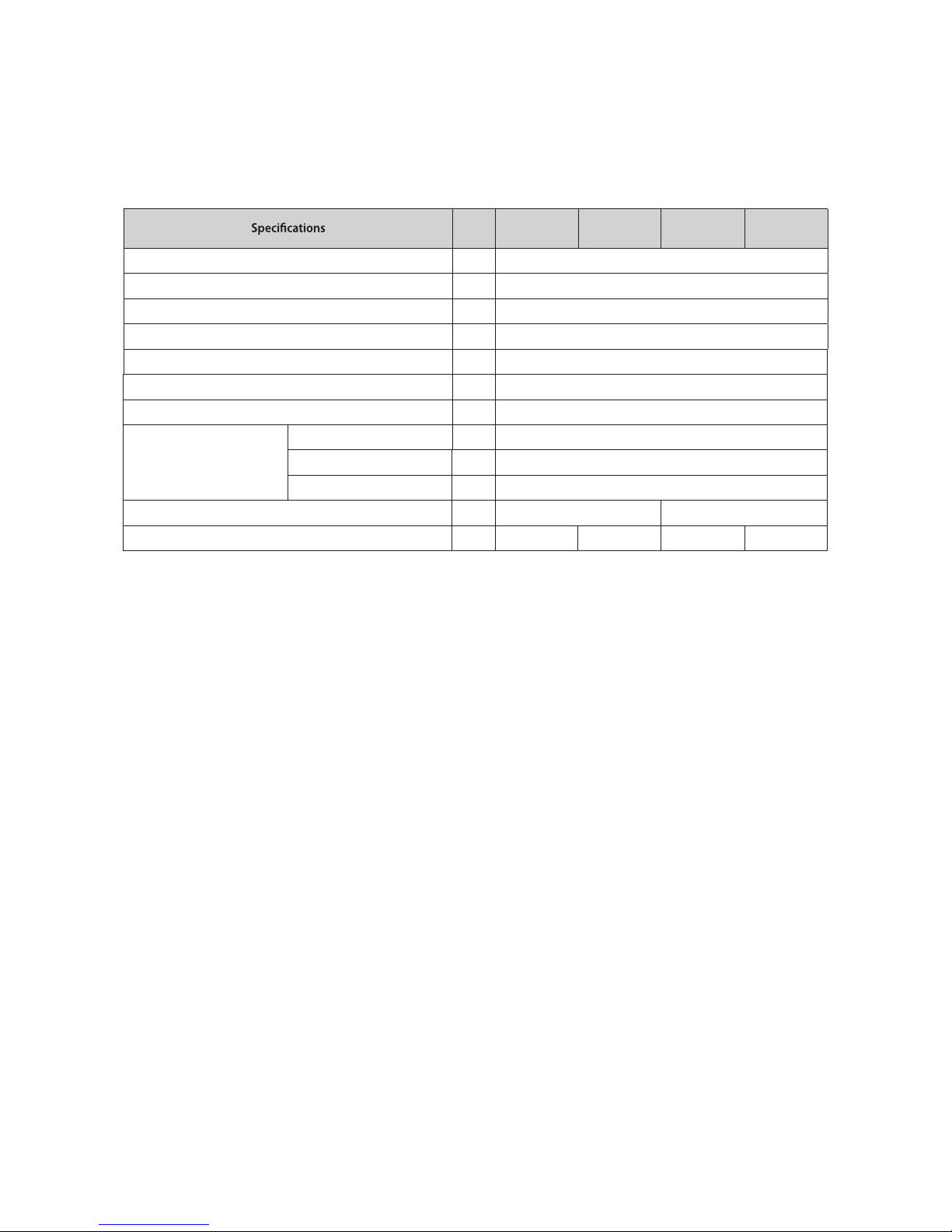
The following table lists the product information requirements (EU regulation No 811/2013 and No 813/2013)
KD Navien Symbol Unit NCB-20LHWE NCB-23LHWE NCB-28LHWE NCB-33LHWE
Condensing boiler YES YES YES YES
Low-temperature (**) boiler NO NO NO NO
B1 boiler NO NO NO NO
Cogeneration space heater NO NO NO NO
Combination heater NO NO NO NO
Rated heat output P
rated
kW 20 23 28 33
Seasonal space heating energy
η
s
% 92 93 93 93
Useful heat output
At rated heat output
and high-temperature regime (*)
P
4
kW 19.5 23.4 28.3 33.2
At 30 % of rated heat output
and low-temperature regime (**)
P
1
kW 6.5 7.8 9.4 11.1
At rated heat output
and high-temperature regime (*)
η
4
% 87.8 87.9 87.9 87.8
At 30 % of rated heat output
and low-temperature regime (**)
η
1
% 97.8 98.1 97.7 98.0
Auxiliary electricity consumption
At full load elmax kW 0.036 0.045 0.048 0.045
At part load elmin kW 0.014 0.015 0.016 0.016
In standby mode P
SB
kW 0.003 0.003 0.003 0.003
Other items
Standby heat loss P
stby
kW 0.080 0.080 0.084 0.084
Ignition burner power
consumption
P
ign
kW ----
Annual energy consumption Q
HE
GJ 37 43 52 57
Sound power level, indoors L
WA
dB 50 52 54 52
Emissions of nitrogen oxides NO
x
mg/kWh 36 38 30 37
Contact details
(*) High-temperature regime means 60 °C return temperature at heater inlet and 80 °C feed temperature at heater outlet.
(**) Low temperature means for condensing boilers 30 °C, for low-temperature boilers 37 °C and for other heaters 50 °C return temperature (at heater inlet).
Read the user’s information and installation manual before the application is assembled, installed or maintained.
3000 Cathedral Hill, Guildford, Surrey, GU2 7YB
10 About the Boiler
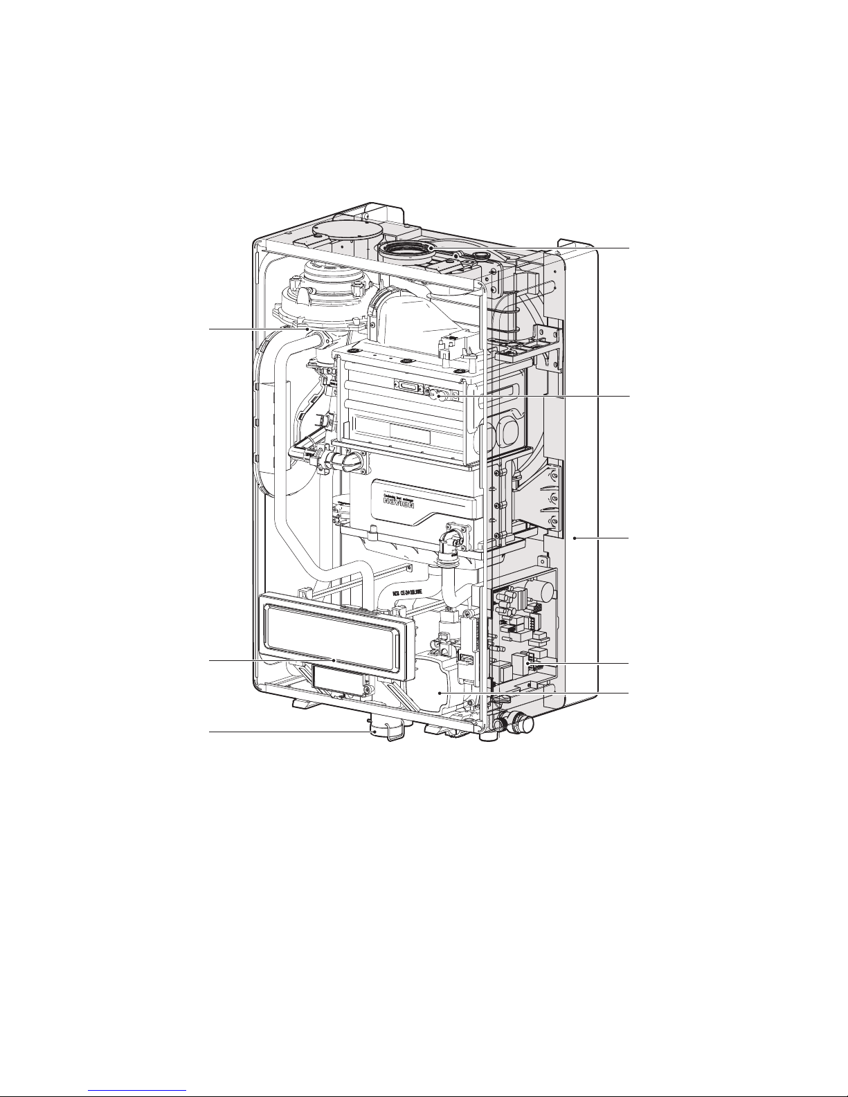
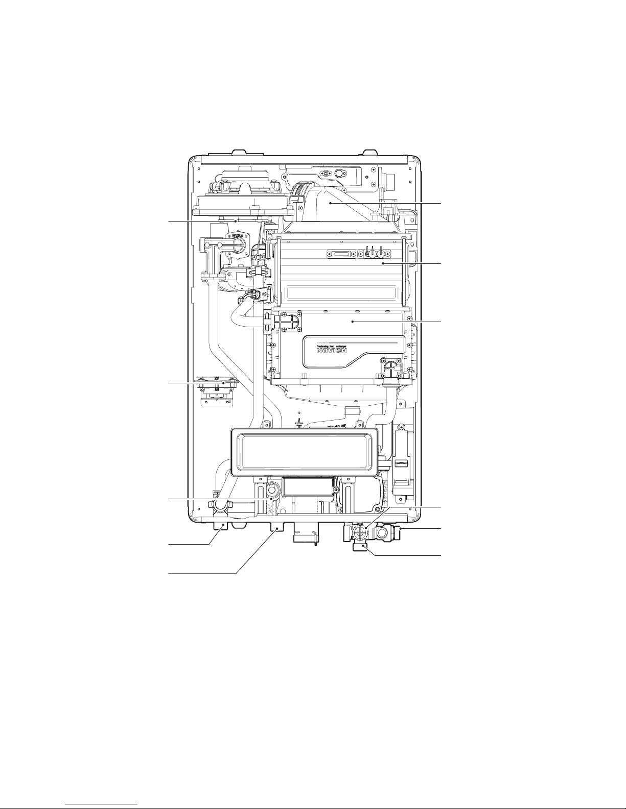
2.4 Components
The following diagram shows the key components of the boiler. Component assembly diagrams and particular parts lists are included in
the Appendices.
Fan & Motor
Front Panel
Flue Duct
Ignitor & Flame Rod
Circulation Pump
Condensate Trap
Mounting Frame
PCB
NCB-20/23/28LHWE
11About the Boiler
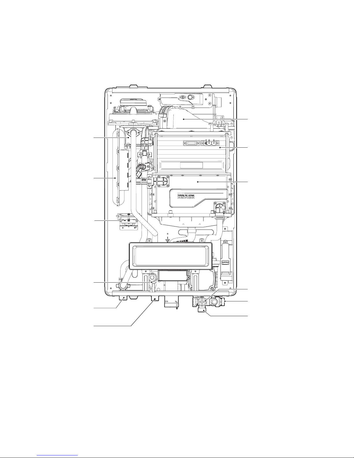
NCB-20/23/28LHWE
Single Venturi
Mixing Chamber
APS
Primary Heat Exchanger
Secondary Heat Exchanger
Return Adapter
Filter Assembly
Space Heating Return
Pressure Relief Valve
Space Heating Supply
Gas supply inlet
Gas Valve
Air Pipe
12 About the Boiler
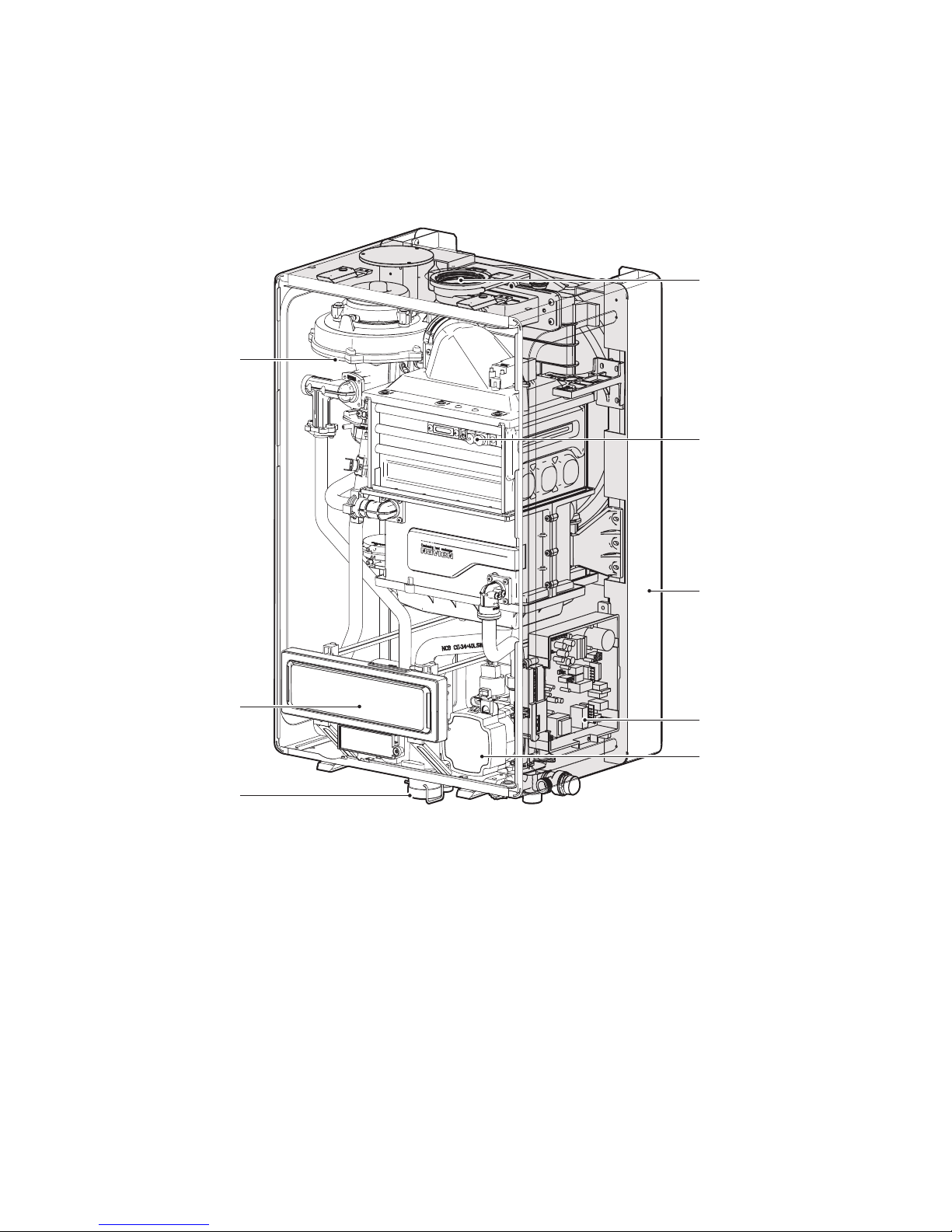
NCB-33LHWE
Fan & Motor
Front Panel
Flue Duct
Ignitor & Flame Rod
Circulation Pump
Condensate Trap
Mounting Frame
PCB
13About the Boiler
NCB-33LHWE
Dual Venturi
Mixing Chamber
Primary Heat Exchanger
Secondary Heat Exchanger
Return Adapter
Filter Assembly
APS
Space Heating Return
Pressure Relief Valve
Space Heating Supply
Gas supply inlet
Gas Valve
14 About the Boiler
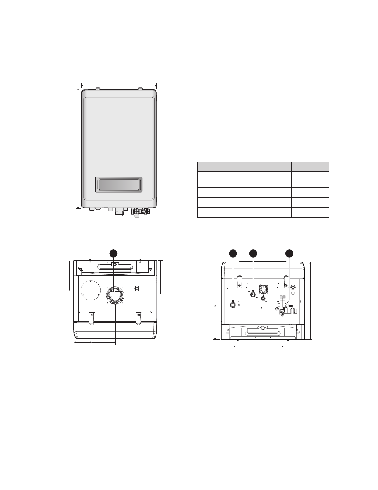
2.5 Dimensions
The following diagrams show the dimensions of the boiler and the table lists the supply connections.
695 mm
440 mm
Supply Connections
Description Diameter
A Flue exhaust/Air intake
Ø60/100,
Ø80/125
B Space heating supply 22 mm
C Gas supply inlet 22 mm
D Space heating return 22 mm
Overhead View
90 mm
157 mm
183 mm
130 mm
A
Bottom View
C
150 mm
D
*NCB-20LHWE/23LHWE: 358 mm
285 mm
-
408 mm*
B
15About the Boiler
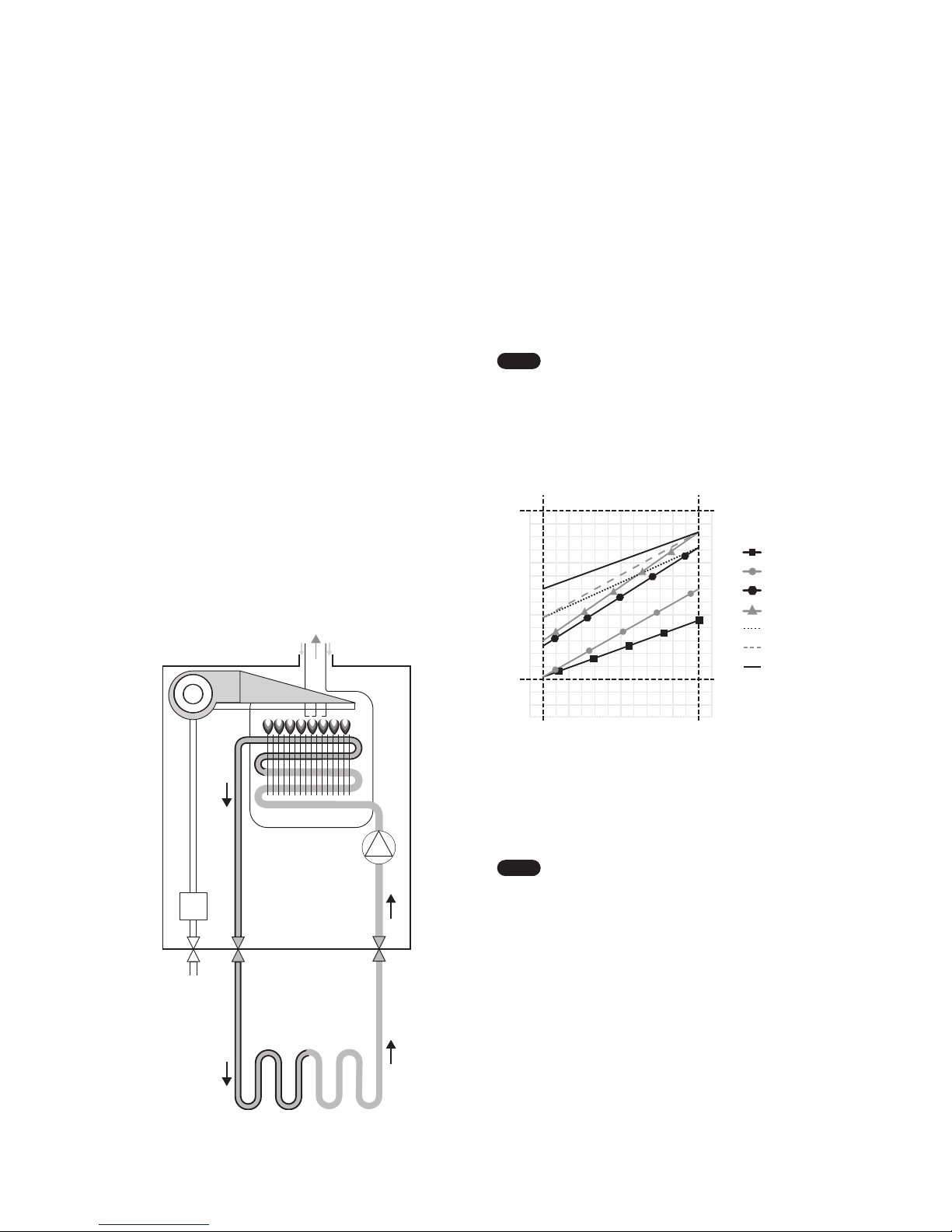
2.6.2 Operating According to Outdoor
Temperature Conditions
The Outdoor Reset Control feature may be used to enhance
energy eciency while maintaining optimal heating
performance. With the Outdoor Reset Control, the space heating
temperature setting automatically changes according to the
outdoor temperature and the current space heating system
application (system load).
You can congure the Outdoor Reset Control settings on the
front panel by entering the Special Parameter Setting mode.
Refer to “11.5 Setting the Parameters” on page 48.
Note
The Outdoor Reset Control feature requires
installation of an outdoor temperature sensor, and it
only works when the boiler is running in the normal
operation mode. It does not work when the boiler is
running in either the Minimum (MIN) or Maximum
(MAX) mode, or when the boiler’s front panel displays
a fault.
45 40 35 30 25 20 15 10 5 0 -5 -10 -15 -20 -25
185
194
176
167
158
149
140
131
122
113
104
95
86
77
68
59
50
113 104 95 86 77 68 59 50 41 32 23 14 5 -4 -13
°F
°C
85
90
80
75
70
65
60
55
50
45
40
35
30
25
20
15
10
°F °C
Absolute
MAX
Absolute
MIN
Outdoor
High MIN
Outdoor
Low MIN
High Mass Radiant
Low Mass Radiant
Cast Iron Baseboard
Custom
Radiator
Finned Tube Baseboard
Fan Coil
Space Heating Temperature Setting for the
Outdoor Reset Control Feature
The following tables list the default space heating temperature
range by system heat load and the applicable outdoor
temperature ranges.
Note
To connect the outdoor temperature sensor to the
boiler, carefully follow the connection instructions
provided in the “13.5 Outdoor Temperature Sensor
(Optional)” on page 72.
2.6 Operating Modes
2.6.1 Operating in Space Heating Mode
To operate the Space heating mode, press the Space heating
button on the front panel and select a heating temperature
setpoint higher than current heating temperature.
1. When the boiler detects a request for heating production
(from the installation’s room thermostat, for example), the
3-way valve goes to heating position and the circulating
pump starts up.
2. If the boiler water temperature is lower than the desired
temperature setpoint, the boiler ignites and heats up the
heating installation until the selected boiler temperature
is reached. The boiler’s electronic control modulates
the burner output to adapt to the installation’s heat
requirements at all times and so that the installation’s water
temperature remains constant. This prevents the installation
from overheating and reduces heat loss as much as possible.
3. When there is no further heating demand (e.g. when
the desired ambient temperature selected on the room
thermostat is reached), the burner is extinguished (if it was
ignited) and the circulation pump continues to run during
the post-circulation time (minimum 3 minutes), to protect
the boiler from overheating due to thermal inertia in the
installation.
Air InAir In
Exhaust
Gas
Blow Fan
Ignitor
Gas
Valve
Gas
Inlet
Flow
Out
CH
Return
Circulation
Pump
Heat
Exchanger
16 About the Boiler
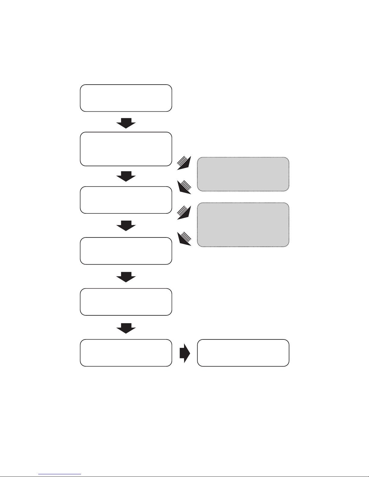
2.7 Installation Procedure
The ow diagram below provides a step-by-step description of the recommended procedure for clear, easy installation of the NCB LHWE
boiler in its nal location. A detailed description is given of the procedure in the sequenced sections below:
Wall-mounting
»
Gas connection
»
Electrical connections
»
DIP switch settings
»
Final check
»
Water and condensate
pipe connection
»
Flue gases exhaustion
system installation
(if necessary)
»
Gas changeover
(if necessary)
»
Boiler operation
»
p. 18
p. 21
p. 25
p. 35
p. 34
54 .p44 .p
p. 28
p. 61
17About the Boiler

3.1 Choosing an Installation Location
When choosing an installation location, you must ensure
that the location provides adequate clearance for the boiler,
adequate ueing and drainage options, and sucient access to
gas, water, and electrical supplies.
Carefully consider the following factors when choosing an
installation location:
Compliance Requirements
This boiler must be installed by qualied personnel in
compliance with the applicable Laws and Regulations.
In general, these Laws and Regulations are the Basic Gas
Installation Standards, the Heating, Air Conditioning and
Domestic Water Installation Regulation and all other local
regulations.
Access to Utilities
Water–the installation location should be near where the
domestic water supply enters the building.
Gas–the installation location should be near where the gas
supply enters the building.
Electricity–the installation location should be near where the
electrical supply enters the building.
Humidity and Contact with Water
When installing the boiler, avoid places with excessive humidity.
The boiler has electric gas ignition components. Water spray or
droppings can get inside the boiler and damage the ignition
system. The boiler must be installed in a way to ensure that
the gas ignition system components are protected from water
(dripping, spraying, rain, etc.) during operation and service.
If the boiler is installed in a very humid room (a shower room
or bathroom, for example), the Low Voltage regulation and
the Technical Building Code must be observed for correct
installation.
Proximity to Fixtures and Appliances
Install the boiler near xtures that deliver or use hot wat
er,
such as bathroom, kitchen, and laundry room faucets. Select
a location that minimises the water piping required between
major xtures. If the distances are long or if the user requires
“instant“ hot water, installation of a recirculation line which
circulates domestic hot water back to the boiler from the
furthest xture is recommended. Insulate as much of the hot
water supply and recirculation lines as possible. For more
information about the water supply, refer to "4.2 Installing a
System Application” on page 22.
Adequate Drainage
The boiler produces a signicant amount of condensate during
operation. This condensate must be removed from the boiler,
and suitably treated if national legislation so requires. The boiler
should be located near a suitable drain and where damage from
a possible leak will be minimal. Installing the boiler in a location
without a drain will void the warranty and Navien will not be
responsible for water damage that occur as a result. For more
information about condensate drainage, refer to “4.3 Connecting
the Condensate Drain Line” on page 22.
The boiler must be located in an area where leakage of the unit
or connections will not result in damage to the area adjacent
to the appliance or to lower oors of the structure. When such
locations cannot be
found, installation of an adequately drained
drain pan under the boiler is highly recommended. When
installing the drain pan, ensure that the installation does not
restrict combustion air ow.
Adequate Flue and Ventilation
The boiler must be installed in a suciently ventilated area with
openings directly to the outside of the building (as required by
the Gas Installations Regulation). The boiler must be located so
that the grilles of the premises are not obstructed and normal
boiler maintenance is possible even if installed between items
of furniture.
Select a location that requires minimal ue. Consider ue
restrictions caused by windows, doors, air intakes, gas meters,
foliage, and other buildings. For more information about ue
system, refer to “6. Flue System” on page 28.
To ensure adequate ue and ventilation, follow these guidelines:
Maintain proper clearances from any openings in the building.
Install the boiler with a minimum clearance of 300 mm above
an exterior grade or as required by local codes.
Do not enclose the ue termination.
Install the exhaust ue in an area that is free from any
obstructions, where the exhaust will not accumulate.
Do not install the boiler where moisture from the exhaust may
discolor or damage walls.
Do not install the boiler in bathrooms, bedrooms, or any
other occupied rooms that are normally kept closed or not
adequately ventilated.
The requirements and recommendations stipulated in the
Regulation for Heating Installations in Buildings (RITE) and any
other applicable legislation in this eld must be observed.
3. Installing the Boiler
18 Installing the Boiler
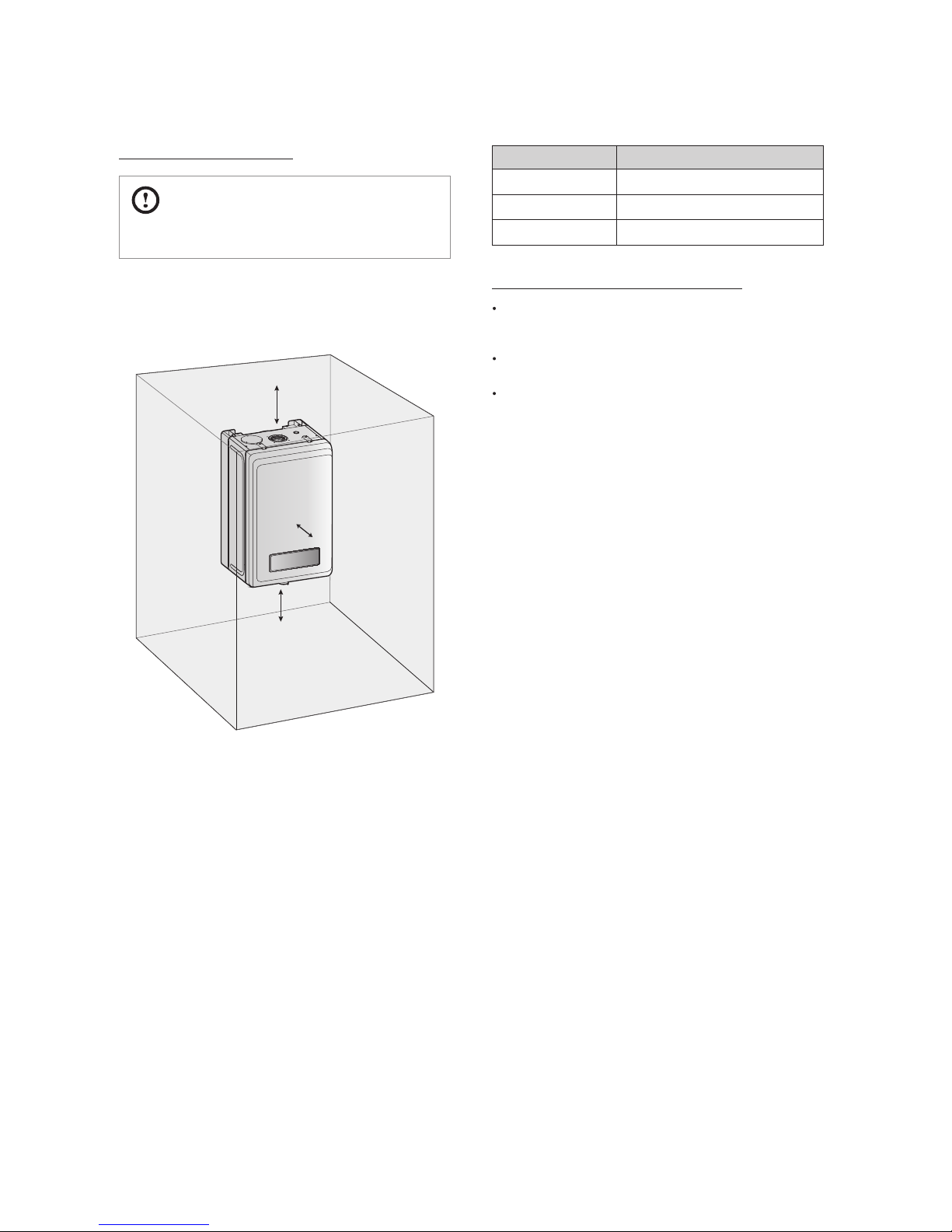
Clearance from: Indoor Installation
Top 250 mm minimum
Front 600 mm minimum
Bottom 200 mm minimum
Clean, debris and chemical-free combustion air
Do not install the boiler in areas where dust and debris may
accumulate or where hair sprays, spray detergents, chlorine,
or similar chemicals are used.
Do not install the boiler in areas where petrol or other
ammables are used or stored.
Ensure that combustible materials are stored away from
the boiler and that hanging laundry or similar items do not
obstruct access to the boiler or its ue system.
Adequate installation clearances
CAUTION
Do not install the boiler on carpeting.
Install the boiler in an area that allows for service and
maintenance access to utility connections, piping, lters,
and traps. Based on the installation location, ensure that the
following clearances are maintained:
Top
Bottom
Front
19Installing the Boiler
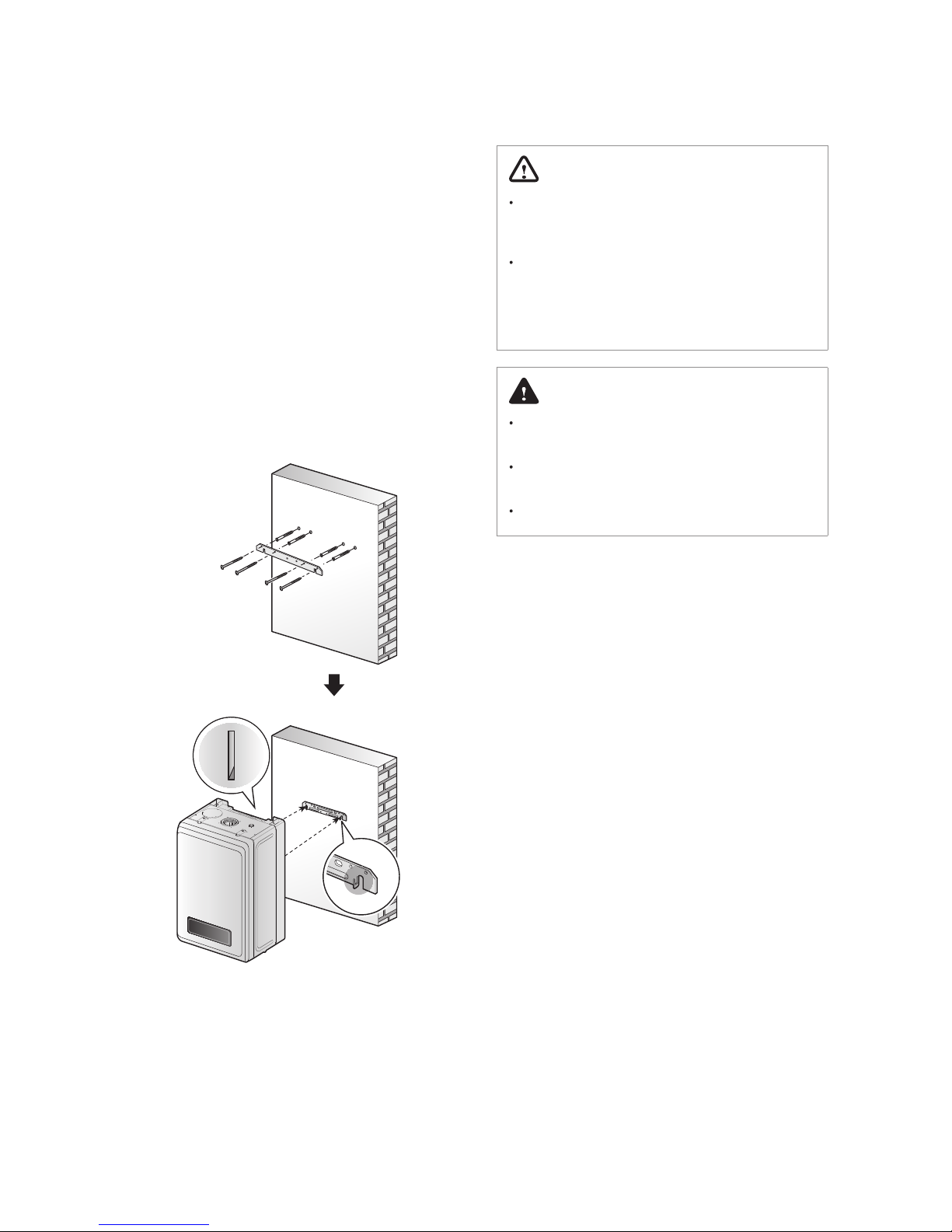
3.2 Mounting the Boiler to the Wall
Navien NCB LHWE boilers come with an upper mounting
bracket that is pre-drilled at 400 mm on center for easy
installation on standard wall studs. If the strength of the wall
is insucient or if the framing is non-standard or uneven,
reinforce the area before installing the boiler. Avoid installation
on common walls as the unit will make some operational noises
while it is running.
To mount the boiler to the wall:
1. Ax the bracket securely to the wall and ensure that it is
level and that it can support the weight of the boiler.
2. Align the grooves on the back of the boiler with the tongues
on the mounting bracket and hang the boiler on the
bracket.
When mounted with the mounting bracket, the boiler will
have a 16 mm clearance from the back of the wall.
WARNING
The boiler is heavy. Always lift the unit with assistance. Be
careful not to drop the boiler while lifting or handling it
to avoid bodily injury or damage to the unit.
Do not rest the boiler on the bottom end after removing
it from the shipping carton. Doing so may result in
excessive pressure on protruding pipes and result in
product damage. If you must put the boiler down, lay it
on its back or put it inside the protective shipping base.
DANGER
The boiler must be mounted on a suitable wall that can
support its weight and prevent explosion or re.
Do not install the boiler near paper or other ammable
objects.
Do not install the boiler near domestic waste.
The installation must be made by suciently qualied
technicians, authorised to do so. For correct installation, all
the requirements and recommendations described in the
Regulation for Heating Installations in Buildings (RITE) must
be complied with, together with all other national and/or local
regulations applicable at the time of installation. However, the
following recommendations must be complied with:
Before connecting the boiler hydraulically, the inside of the
pipes must be thoroughly cleaned, removing all sediment of
any type which could cause oxidation or damage to the heat
exchanger.
It is recommended to t shut-o valves to the heating
installation output and return pipes, to avoid having to drain
the installation when maintenance work is carried out on the
boiler.
Bleed the air from the boiler and heating installation. Ensure
there is no air in the heating circuit.
The NCB LHWE boiler is a condensing boiler, and it is
therefore essential for the condensate outlet to lead to a
drain, in compliance with all applicable national and/or local
regulations to this respect.
The boiler drain must not be located above a window, entry
door or other public point of access. Bear in mind that boiling
water or steam could come out when draining.
Draining must be done in a downward direction and towards
the walls.
WARNING
Tighten the boiler water connections, taking care not
to damage them. Do not force the tube connections
excessively, as this could damage the connections and
cause leaks.
Any dirt in the tubes could reduce boiler eciency and
cause it to malfunction.
Any pipes exposed to the elements or which could freeze
in winter must be insulated with suitable insulating
material.
CAUTION
Failure to follow the instructions provided in this section will
void the warranty and may result in property damage, re
or serious injury.
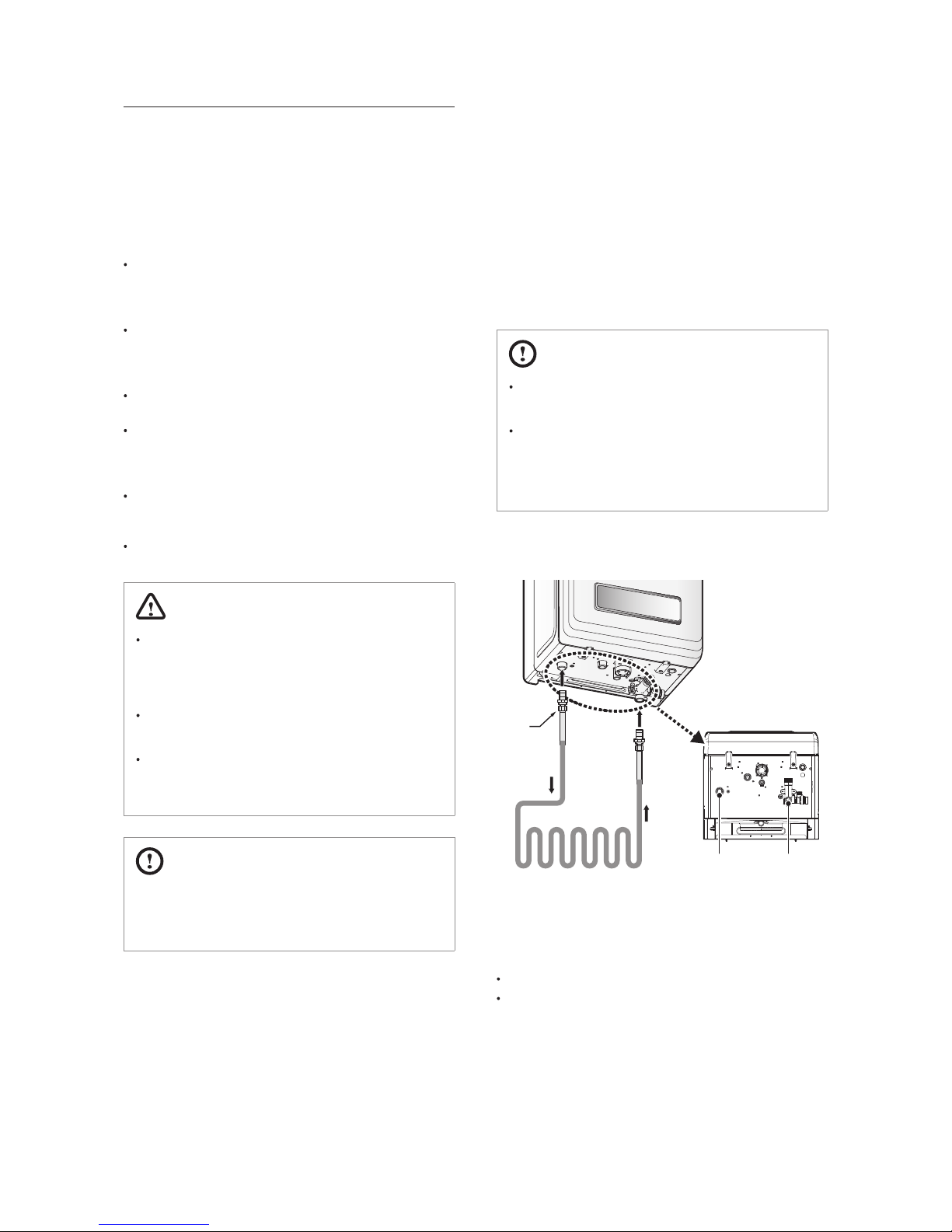
4. Installing the System Piping
4.1 Installing a Space Heating System
The primary and secondary heat exchangers of the Navien
NCB LHWE boiler are designed to attain the highest level of
heat transfer in a compact design. To accomplish this, the
heating water ows through a series of tubes (secondary
heat exchanger) and nned tubes (primary heat exchanger),
designed to maximise the heat transfer area. To maintain the
ecient and reliable operation of the heat exchangers, and to
avoid heat exchanger failure, it is critical to ensure the rules and
guidelines in this section are followed.
CAUTION
The installation must be made by suciently qualied
technicians, authorised to do so.
For correct installation, all the requirements and
recommendations described in the Regulation for
Heating Installations in Buildings (RITE) must be
complied with, together with all other national and/or
local regulations applicable at the time of installation.
Refer to the following illustration for a typical heating piping
example for the boiler.
Union
CH Flow
CH Return
Bottom View
Floor Heating Circuit or
Heating Circuit (Radiator)
Heating Supply
Adapter
Heating Return
Adapter
When connecting the space heating system, follow these
guidelines:
Tighten the connection valves with care to avoid damage.
Test the boiler for proper space heating ow and inspect for
leaks.
20 Installing the Boiler
The installation must be made by suciently qualied
technicians, authorised to do so. For correct installation, all
the requirements and recommendations described in the
Regulation for Heating Installations in Buildings (RITE) must
be complied with, together with all other national and/or local
regulations applicable at the time of installation. However, the
following recommendations must be complied with:
Before connecting the boiler hydraulically, the inside of the
pipes must be thoroughly cleaned, removing all sediment of
any type which could cause oxidation or damage to the heat
exchanger.
It is recommended to t shut-o valves to the heating
installation output and return pipes, to avoid having to drain
the installation when maintenance work is carried out on the
boiler.
Bleed the air from the boiler and heating installation. Ensure
there is no air in the heating circuit.
The NCB LHWE boiler is a condensing boiler, and it is
therefore essential for the condensate outlet to lead to a
drain, in compliance with all applicable national and/or local
regulations to this respect.
The boiler drain must not be located above a window, entry
door or other public point of access. Bear in mind that boiling
water or steam could come out when draining.
Draining must be done in a downward direction and towards
the walls.
WARNING
Tighten the boiler water connections, taking care not
to damage them. Do not force the tube connections
excessively, as this could damage the connections and
cause leaks.
Any dirt in the tubes could reduce boiler eciency and
cause it to malfunction.
Any pipes exposed to the elements or which could freeze
in winter must be insulated with suitable insulating
material.
CAUTION
Failure to follow the instructions provided in this section will
void the warranty and may result in property damage, re
or serious injury.
4. Installing the System Piping
4.1 Installing a Space Heating System
The primary and secondary heat exchangers of the Navien
NCB LHWE boiler are designed to attain the highest level of
heat transfer in a compact design. To accomplish this, the
heating water ows through a series of tubes (secondary
heat exchanger) and nned tubes (primary heat exchanger),
designed to maximise the heat transfer area. To maintain the
ecient and reliable operation of the heat exchangers, and to
avoid heat exchanger failure, it is critical to ensure the rules and
guidelines in this section are followed.
CAUTION
The installation must be made by suciently qualied
technicians, authorised to do so.
For correct installation, all the requirements and
recommendations described in the Regulation for
Heating Installations in Buildings (RITE) must be
complied with, together with all other national and/or
local regulations applicable at the time of installation.
Refer to the following illustration for a typical heating piping
example for the boiler.
Union
CH Flow
CH Return
Bottom View
Floor Heating Circuit or
Heating Circuit (Radiator)
Heating Supply
Adapter
Heating Return
Adapter
When connecting the space heating system, follow these
guidelines:
Tighten the connection valves with care to avoid damage.
Test the boiler for proper space heating ow and inspect for
leaks.
21Installing the System Piping
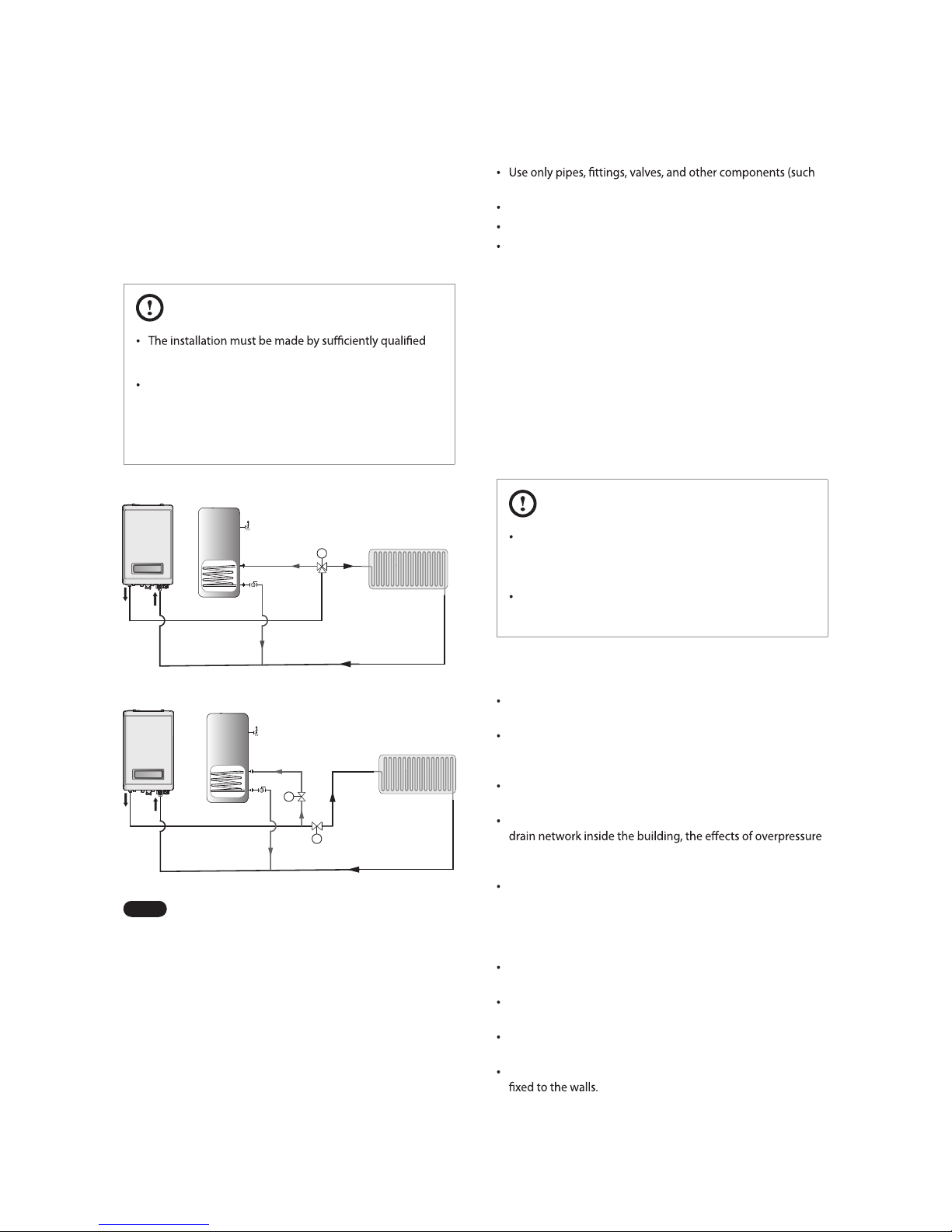
4.2 Installing a System Application
Refer to the following examples to properly implement a
system for space heating, DHW supply, or both. These examples
are provided to suggest basic guidelines when you installing
the boiler system. However, the actual installation may vary
depending on the circumstances, local building codes or
regulations.
CAUTION
technicians, authorised to do so.
For correct installation, all the requirements and
recommendations described in the Regulation for
Heating Installations in Buildings (RITE) must be
complied with, together with all other national and/or
local regulations applicable at the time of installation.
M
M
M
S Plan Layout
Y Plan Layout
Note
Refer to the “7. Setting the DIP Switches” and “11.5
Setting the Parameters” to control the boiler using the
external CH Controller and DHW Tank.
When installing the system, follow these guidelines:
as solder), that are approved for use in potable water systems.
Tighten the connection valves with care to avoid damage.
The external hydraulic bypass valve is required.
An additional expansion vessel must be installed to the
system in the central heating return.
4.3 Connecting the Condensate Drain
Line
The Navien NCB LHWE boiler creates condensation when it
operates. This condensation has an acidic pH of 3-5. Follow
all local codes and regulations when disposing of condensate
from the boiler. We recommend draining the condensate into
a laundry tub, as the alkali in laundry detergent will neutralise
the acid in the condensate. However, other suitable waste drain
locations may be used according to the local legislation.
CAUTION
Do not cap or plug the integrated condensate line. If
prevented from draining, condensate can damage the
boiler.
The condensate line must have a negative slope to drain
properly.
The requirements recommended for the condensate drain line
installation are as follows:
For correct condensate drain line installation, the tube must
have a minimum diameter of Ø21.5 mm.
The tube must be made of a material that can withstand
corrosion, e.g. PVC, PVC-U, ABS, PVC-C or PP. It must not be
made of metal.
For safety reasons, the end of the tube must be as close as
possible to the draining point.
When the condensate drainage is connected to a general
that could occur inside it must be taken into account,
installing suitable pressure release and ventilation elements.
The length of the tubes outside the building must be as short
as possible. They must also be installed with as much tilt as
possible. The tubes must be insulated if they are exposed
to extremly cold weather or blizzards. If the tubes are not
insulated, they must have a diameter of at least Ø32 mm.
The drain tube must have a minimum tilt of 2.5° downstream
of the boiler.
For tubes with Ø21.5 mm, the maximum permitted length is
3 metres.
If the appliance is installed in a non-heated premises, the tube
system must be treated as if it was an outdoor installation.
To prevent the risk of tripping, the outdoor tubes must be
22 Installing the System Piping
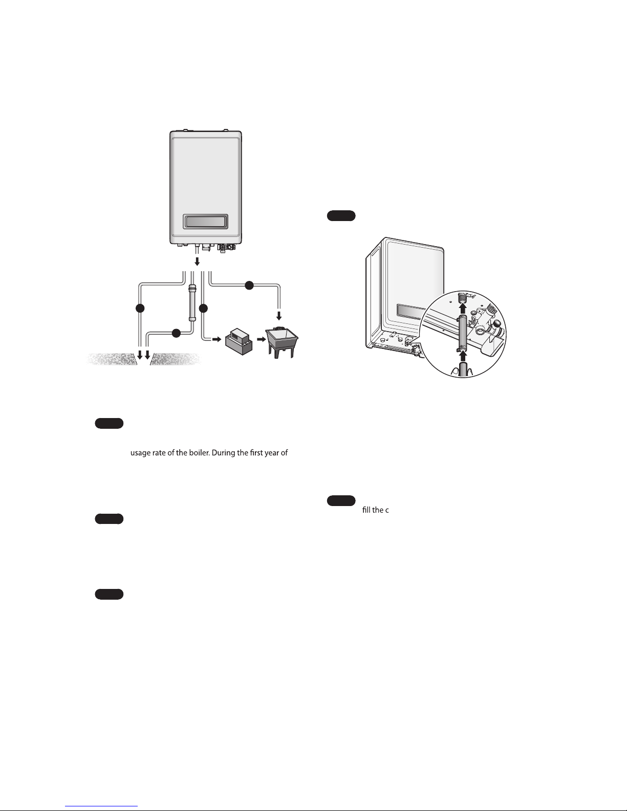
Before connecting the condensate drain, choose one of the
following disposal options:
a
b
c
d
a. From the boiler directly into an external drain.
b. From the boiler, through a neutralizing agent, and then
into an external drain.
Note
If you choose this option, the neutralizing agent
must be replaced periodically. Depletion of
the neutralising agent will vary, based on the
operation, the neutralizer should be checked
every few months for depletion and replaced as
needed.
c. From the boiler into a laundry tub.
Note
The bottom of the boiler must be higher than
the top of the laundry tub to use this option. The
condensate line must have a negative slope to
drain properly.
d. From the boiler into a condensate pump, and then into a
laundry tub.
Note
A pump can be used when there is a long
distance between the boiler and the laundry tub
or when the bottom of the boiler is lower than the
top of the laundry tub.
2. Place the free end of the drain line into an appropriate drain.
3. If you are using a condensate pump, ensure that the pump
allows for up to 3.78 LPH of drainage for each boiler in the
system.
4. If you are not using a condensate pump, ensure that the
drain line is pitched downward at a minimum slope of 6 mm
per 30 cm.
Note
Water must be poured into the exhaust connection to
ondensate trap.
To connect the condensate drain:
1. Connect a drain line to the condensate trap.
The condensate trap outlet will allow 21.5mm.
Use only corrosion-resistant material for the drain line,
such as PVC or CPVC. Do not reduce the size of the drain
line to less than 21.5mm.
The drain line can be connected to the condensate trap
using a condensate trap hose. The hose connection
must be secured with a hose clip.
Note
This hose is supplied along with the boiler.
23Installing the System Piping
4.4 Pressure Relief Valve
The requirements recommended for the pressure relief valve are
as follows:
The pressure relief valve is calibrated to be activated at a
maximum pressure of 3 bar, and all the pipes and connections
must therefore be able to withstand pressures of up to 3 bar.
Connect the pressure relief valve drain to a tube with a
diameter of at least Ø15 mm. It must tilt in a downstream
direction throughout its entire length, and the water must run
o to a suitable drain. It must be positioned so as not to cause
damage to cabling, electrical equipment or persons.
The drain must not be located above a window, entry door or
any other public access point. Bear in mind that boiling water
or steam could come out when draining.
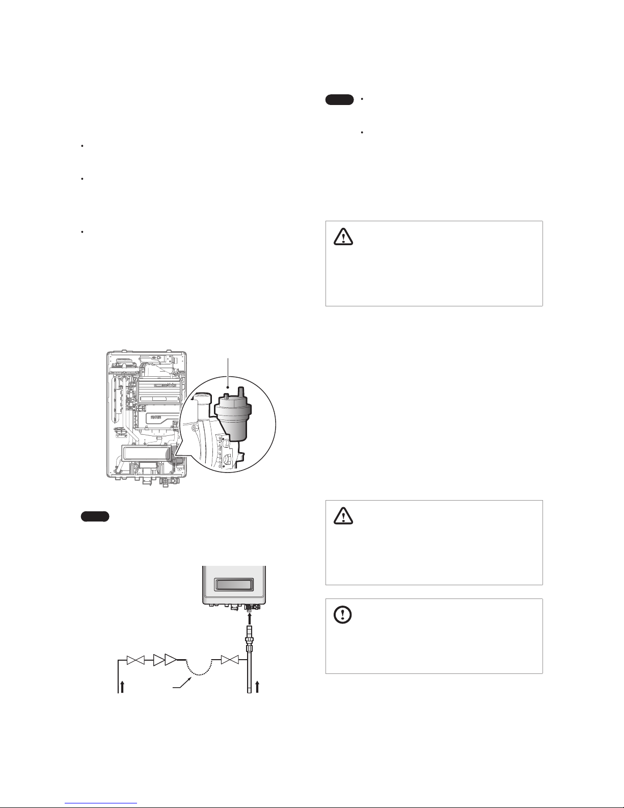
4.5 Filling the system
Before lling the boiler pipes, pull up the air ue cap to allow the
pipes to ll properly. Press the cap back in when the pipes are
full.
Air Flue Cap
Note
Ensure that the ue cap is tted before testing or
operating the system.
Refer to the following illustration for system ll.
Stop
Valve
Cold mains Inlet
Temporary
Loop
Space hating Return
Stop
Valve
Double
Check
Valve
Note
The system must be lled with approved
equipment and comply with all regulations for
system ll.
To perform an air purge after initially lling the
boiler pipes, the pump will run for 5 minutes and
20 seconds. The boiler will operate normally after
performing an air purge.
4.6 Testing the Water System
WARNING
Ensure that the boiler is full of water before ring the burner.
Operating the unit without lling it will damage the boiler.
Such damage is not covered by the warranty, and may result
in property damage or severe personal injury.
Perform a ll test after installing the boiler’s water system to
make sure that the system has been installed properly. Follow
the instructions below to perform a ll test on the water system.
1. Close the manual air ues and the boiler drain valve.
2. Fill the boiler. The correct pressure will vary with each
application.
3. If the pressure is lower than the minimum pressure set (1 bar
by default), error code E02 will appear on the display.
4. Fill the boiler with more water until the error message
disappears.
5. At initial ll and during boiler start
-up and testing, check
the system thoroughly for leaks. Repair any leaks before
proceeding further.
WARNING
Eliminate all system leaks. The continual introduction of fresh
makeup water will reduce boiler life. Minerals can build up in
the heat exchanger, reducing heat transfer, overheating the
heat exchanger and causing heat exchanger failure.
CAUTION
Before operating the boiler for the rst time, ensure that the
boiler system is lled with water. Purge the air inside the
system to avoid damage to the boiler.
WARNING
If a gas type other than the one specied on the boiler
reference plate is used, it could cause a re or even an
explosion.
It is important to ensure that the gas supply is suitable
for the type and capacity of the boiler.
Thoroughly check the seal and draining of the entire
installation, as a gas leak could cause serious damage.
DANGER
Gas leaks can cause explosions resulting in serious
personal and material damage.
Keep all doors and windows open while you are bleeding
the gas pipes and put out any cigarettes, ames or other
possible source of ignition.
For the installation of any type of gas, the installer must be
authorised by the Ministry of Industry and strictly follow the
applicable Gas Regulations. The gas installation must comply
with the Gas Installation Regulation.
However, the following recommendations must be complied
with, at the least:
Before installing the gas pipes, check the type of gas is
compatible with the boiler.
Check that the gas meter in the home can measure the rate of
gas supply required.
The gas pipe diameter is not determined by the boiler
connection. It should be calculated in accordance with its
length and consequently its pressure drop.
The pipes must be directly connected to the main gas supply
pipe, not connected in parallel to other gas appliances.
Check there are no leaks from the installation.
The gas supply company is solely responsible for connecting
the gas meter to the gas installation.
To connect the gas supply:
1. Connect the gas supply pope to the connection located on
the underside of the apliance.
2. After completing the gas installation, check there are no
leaks and bleed the air from all the pipes, following the
procedures described in the applicable standards to this
respect.
Gas Shuto Valve
Gas Supply
Union
Bottom View
Gas Inlet Adapter
Union
5. Connecting the Gas Supply
24 Installing the System Piping
 Loading...