

Navien NCB-150E, NCB-180E, NCB-210E, NCB-240E Operation Manual
WARNING
If the information in these instructions is not followed exactly, a re or explosion may result, causing
property damage, personal injury or death.
Do not store or use gasoline or other ammable vapors and liquids in the vicinity of this or any other
appliance.
What to do if you smell gas
Do not try to light any appliance.
Do not touch any electrical switch; do not use any phone in your building.
Immediately call your gas supplier from a neighbor’s phone. Follow the gas supplier’s instructions.
If you cannot reach your gas supplier, call the re department.
Installation and service must be performed by a qualied installer, service agency or the gas supplier.
The installation must conform with local codes or, in the absence of local codes, the National Fuel Gas Code,
ANSIZ223.1/NFPA 54 and/or CSA B149.1, Natural Gas and Propane Installation Code.
H
NSF/ANSI 372
Keep this manual near this boiler for future reference whenever
maintenance or service is required.
* The wetted surface of this product contacted by consumable water contains less than
one quarter of one percent (0.25%) of lead by weight.
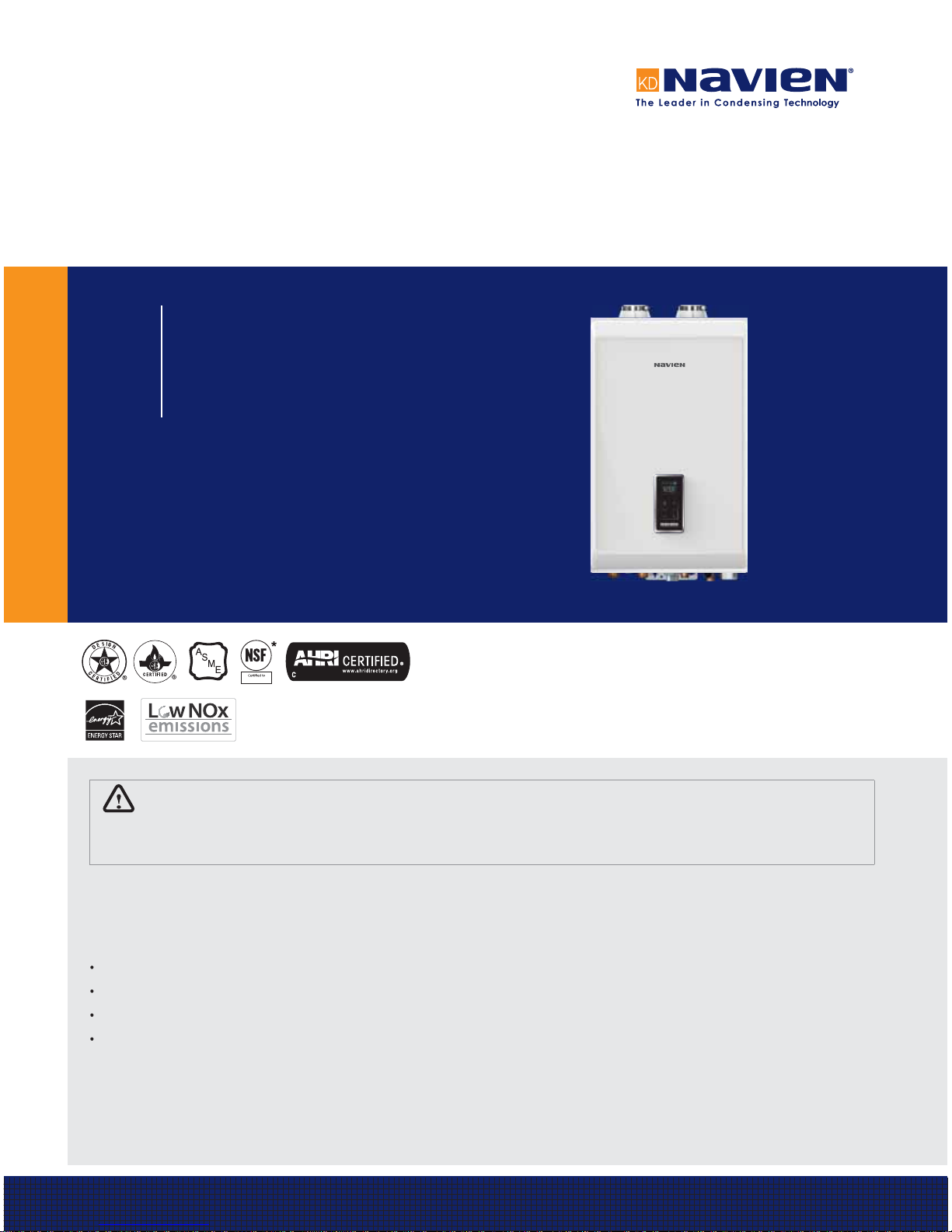
Installation & Operation Manual
NCB-E Condensing Combi-Boilers
Model
NCB-150E
NCB-180E
NCB-210E
NCB-240E

2
Requirements for the State of Massachusetts
NOTICE BEFORE INSTALLATION
This appliance must be installed by a licensed plumber or gas fitter in accordance with the Massachusetts Plumbing and Fuel Gas
Code 248 CMR Sections 2.00 and 5.00.
IMPORTANT: In the State of Massachusetts (248 CMR 4.00 & 5.00)
For all side wall horizontally vented gas fueled equipment installed in every dwelling, building or structure used in whole or in part for
residential purposes, including those owned or operated by the Commonwealth and where the side wall exhaust vent termination is less than
seven (7) feet above finished grade in the area of the venting, including but not limited to decks and porches, the following requirements shall
be satisfied:
1. INSTALLATION OF CARBON MONOXIDE DETECTORS. At the time of installation of the side wall horizontal vented gas fueled equipment,
the installing plumber or gasfitter shall observe that a hard wired carbon monoxide detector with an alarm and battery backup is
installed on the floor level where the gas equipment is to be installed. In addition, the installing plumber or gasfitter shall observe that a
battery operated or hard wired carbon monoxide detector with an alarm is installed on each additional level of the dwelling, building or
structure served by the side wall horizontal vented gas fueled equipment. It shall be the responsibility of the property owner to secure the
services of qualified licensed professionals for the installation of hard wired carbon monoxide detectors
a. In the event that the side wall horizontally vented gas fueled equipment is installed in a crawl space or an attic, the hard wired carbon
monoxide detector with alarm and battery backup may be installed on the next adjacent floor level.
b. In the event that the requirements of this subdivision cannot be met at the time of completion of installation, the owner shall have a
period of thirty (30) days to comply with the above requirements; provided, however, that during said thirty (30) day period, a battery
operated carbon monoxide detector with an alarm shall be installed.
2. APPROVED CARBON MONOXIDE DETECTORS. Each carbon monoxide detector as required in accordance with the above provisions shall
comply with NFPA 720 and be ANSI/UL 2034 listed and IAS certified.
3. SIGNAGE. A metal or plastic identification plate shall be permanently mounted to the exterior of the building at a minimum height of
eight (8) feet above grade directly in line with the exhaust vent terminal for the horizontally vented gas fueled heating appliance or
equipment. The sign shall read, in print size no less than onehalf (1/2) inch in size, “GAS VENT DIRECTLY BELOW. KEEP CLEAR OF ALL
OBSTRUCTIONS”.
4. INSPECTION. The state or local gas inspector of the side wall horizontally vented gas fueled equipment shall not approve the installation
unless, upon inspection, the inspector observes carbon monoxide detectors and signage installed in accordance with the provisions of
248 CMR 5.08(2)(a)1 through 4.

Contents 3
Contents
Safety Information 4
1. About the Boiler
7
1.1 Items Included 7
1.2 Accessories 7
1.3 Specifications
8
1.4 Components
10
1.5 Dimensions 12
1.6 Rating Plate
13
2. Installing the Boiler 14
2.1 Choosing an Installation Location 14
2.2 Mounting the Boiler to the Wall 16
3. Installing the System Piping 17
3.1 Installing a Space Heating System 17
3.2 Installing a Domestic Hot Water (DHW) System
20
3.3 Connecting the Condensate Drain
23
3.4 System Fill Connection
26
3.5 Testing the Water System
27
3.6 Examples of System Applications 27
4. Installing a Cascading System 32
4.1 Connecting Water Supplies 32
4.2 Connecting the Communication Cables 33
4.3 Configuring the Communication Settings
33
5. Connecting the Gas Supply 35
5.1 Gas Pipe Sizing Tables 37
5.2 Measuring the Inlet Gas Pressure 38
6. Venting the Boiler 40
6.1 Selecting a Vent Type 40
6.2 Selecting Vent Pipe Materials 44
6.3 Measuring Vent Length
45
7. Setting the DIP Switches 48
7.1 PCB DIP Switches 48
7.2 Front Panel Dip Switches 49
8. Connecting the Power Supply 50
9. Installation Check list
51
10. Operating the Boiler
54
10.1 Turning the Boiler On or Off 54
10.2 Adjusting the Temperature
54
10.3 Viewing Basic Information 55
10.4 Setting the Operation Mode
56
10.5 Setting the Parameters 56
10.6 Resetting the Boiler
63
11. Appendixes 64
11.1 Gas Conversion 64
11.2 Wiring Diagram
70
11.3 Ladder Diagram 71
11.4 Component Assembly Diagrams and Parts Lists
72
11.5 Outdoor Temperature Sensor (Optional)
80
11.6 Outdoor Reset Control (Available with Optional
Outdoor Temperature Sensor)
80
4 Safety Information
The following safety symbols are used in this manual. Read and
follow all safety instructions in this manual precisely to avoid
unsafe operating conditions, fire, explosion, property damage,
personal injury, or death.
DANGER
Indicates an imminently hazardous situation which, if not
avoided, could result in severe injury or death.
WARNING
Indicates a potentially hazardous situation which, if not
avoided, could result in injury or death.
CAUTION
Indicates a potentially hazardous situation which, if not
avoided, could result in property damage.
DANGER
If you smell gas:
Ɣ
Do not try to light any appliance.
Ɣ
Do not touch any electrical switches or use landline phones.
Ɣ
From a neighbor’s phone, call your gas provider and follow
their instructions.
Ɣ
If you cannot reach your gas provider, call the fire
department.
Ɣ
Do not return to your home until authorized by your gas
supplier or the fire department.
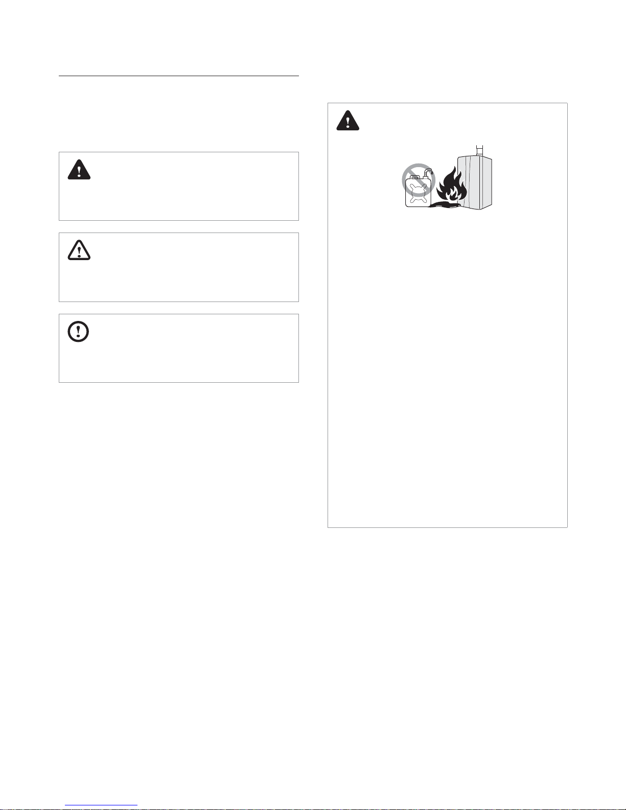
Do not use or store flammable products, such as gasoline,
solvents, or adhesives in the same room or area as the
boiler.
Ɣ
The boiler has a main burner flame that can turn on at
any time and can ignite flammable vapors. Vapors from
flammable liquids can explode and catch fire, causing death
or severe burns.
Ɣ
Vapors cannot be seen and are heavier than air. They can
travel long distances along the ground and can be carried
from other rooms to the boiler’s main burner flame by air
current.
Ɣ
Keep all flammable products far away from the boiler and
store them in approved containers. Keep the containers
closed tightly and out of the reach of children and pets.
Safety Information
Safety Information 5
CAUTION
Ɣ
Do not turn on the boiler unless the water and gas
supplies are fully opened.
Doing so may damage the boiler.
Ɣ
Do not turn on the water if the cold water supply shutoff valve is closed.
Doing so may damage the boiler.
Ɣ
Do not use this boiler for anything other than its
intended purpose, as described in this manual.
Ɣ
When servicing the controls, label all wires prior to
disconnecting them.
Failure to do so may result in wiring errors, which can lead to
improper or dangerous operation. Verify proper operation
after servicing.
Ɣ
Do not use unapproved replacement or accessory parts.
Doing so may result in improper or dangerous operation
and will void the manufacturer’s warranty.
Ɣ
Do not place anything in or around the vent terminals,
such as a clothes line, that could obstruct the air flow in
or out of the boiler.
Ɣ
This boiler has been approved for use in the USA and
Canada only.
Using the boiler in any other country will void the
manufacturer’s warranty.
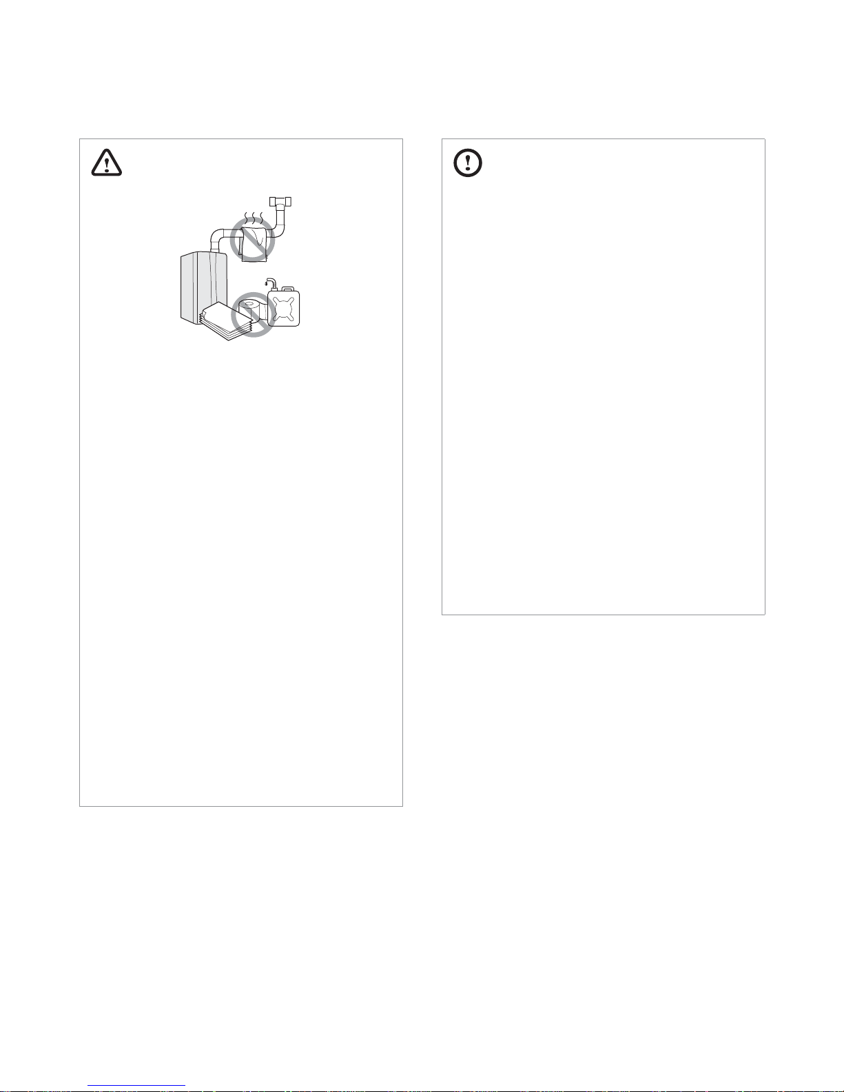
WARNING
Ɣ
Do not store or use gasoline or other flammable liquids
near this boiler.
Doing so may result in fire or explosion.
Ɣ
Do not place combustibles, such as newspapers or
laundry, near the boiler or venting system.
Doing so may result in a fire.
Ɣ
Do not place or use hair sprays, spray paints, or any other
compressed gases near the boiler or venting system,
including the vent termination.
Doing so may result in fire or explosion.
Ɣ
Do not remove the front cover unless the power to the
boiler is turned off or disconnected.
Failure to do so may result in electric shock.
Ɣ
Do not operate the boiler with the front cover opened.
Doing so may result in fire or carbon monoxide (CO)
poisoning, which may result in property damage, personal
injury, or death.
Ɣ
Do not operate this boiler without proper venting.
Doing so may result in fire or carbon monoxide (CO)
poisoning, which may result in property damage, personal
injury, or death.
Ɣ
Do not touch the power cord or internal components of
the boiler with wet hands.
Doing so may result in electric shock.
6 Safety Information
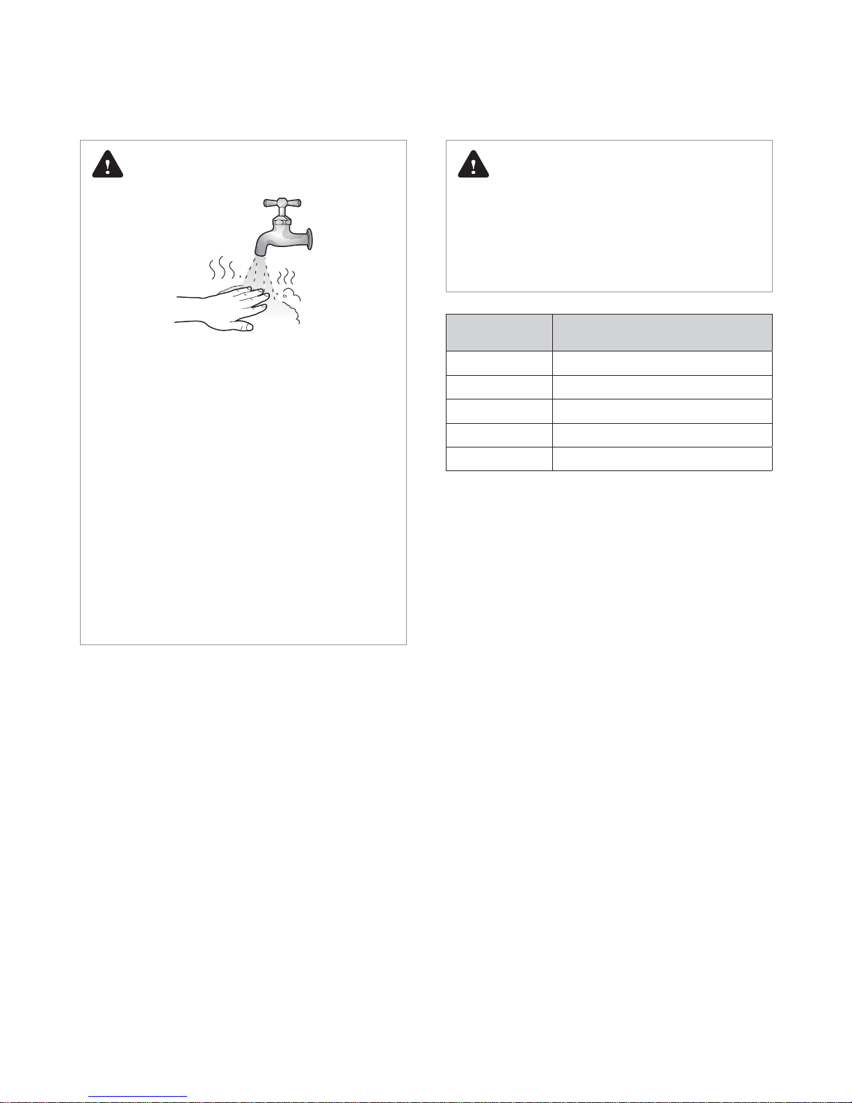
DANGER
This boiler’s water temperature is set to 120°F (49°C) at the
factory for your safety and comfort. Increasing the temperature
increases the risk of accidental scalding. Water temperatures at
or above 125°F (52°C) can cause instant scalding, severe burns,
or death. Before you decide to change the temperature setting,
read the following charts carefully.
Water
Temperature
Time in which a young child can suffer a
full thickness (3rd degree) burn
160°F (70°C) Less than 1 second
140°F (60°C) 1 second
130°F (55°C) 10 seconds
120°F (49°C) 10 minutes
100°F (37°C) very low scald risk
DANGER
HOT
BURN
To prevent burns:
Ɣ
Use the lowest operating temperature setting necessary to
provide comfortably-hot water.
Ɣ
If your household has children or elderly or disabled
residents, consider using a lower temperature setting.
Ɣ
Read all the instructions in this manual carefully before
changing the temperature setting.
Ɣ
Feel the water before using it on children, the elderly, or the
disabled.
Ɣ
If it is necessary to set the water temperature above 125°F
(52°C), consider installing a thermostatically-controlled
mixing valve or temperature-limiting valve. Contact a
licensed plumber or your local plumbing authority for more
information.
About the Boiler 7
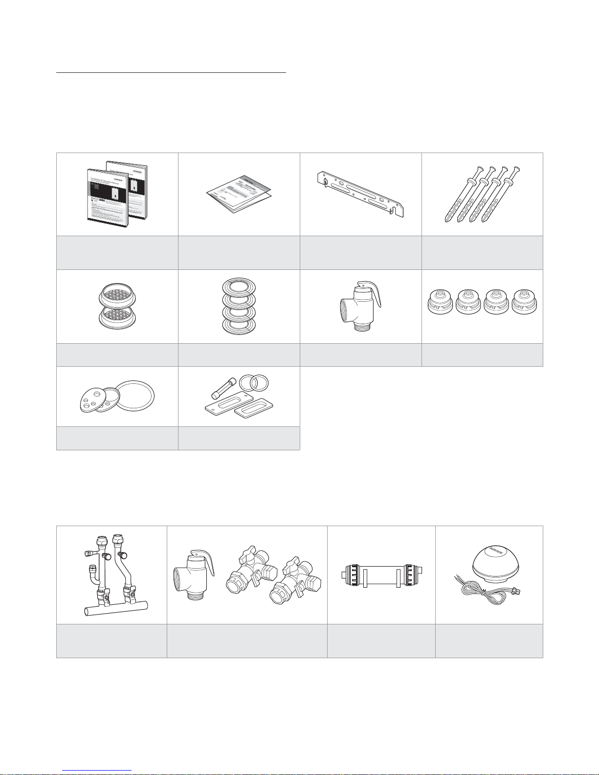
1.1 Items Included
When you open the box, you will find the following items with the boiler. Check the box for each of the following items before installing the
boiler.
Installation & Operation Manual,
User’s Information Manual
Quick Installation Manual Wall Mounting Bracket Tapping Screws & Anchors
2 in Vent Termination Caps 2 in Wall Flanges Pressure Relief Valve, Heating Flow Restrictors
Conversion Kit Spare Parts
1.2 Accessories
The following optional accessories are available for the boiler:
Navien Manifold System
Plumb Easy Valve Set
(Pressure Relief Valve, DHW)
Condensate Neutralizer
Outdoor Temperature
Sensor with Cable
1. About the Boiler
8 About the Boiler
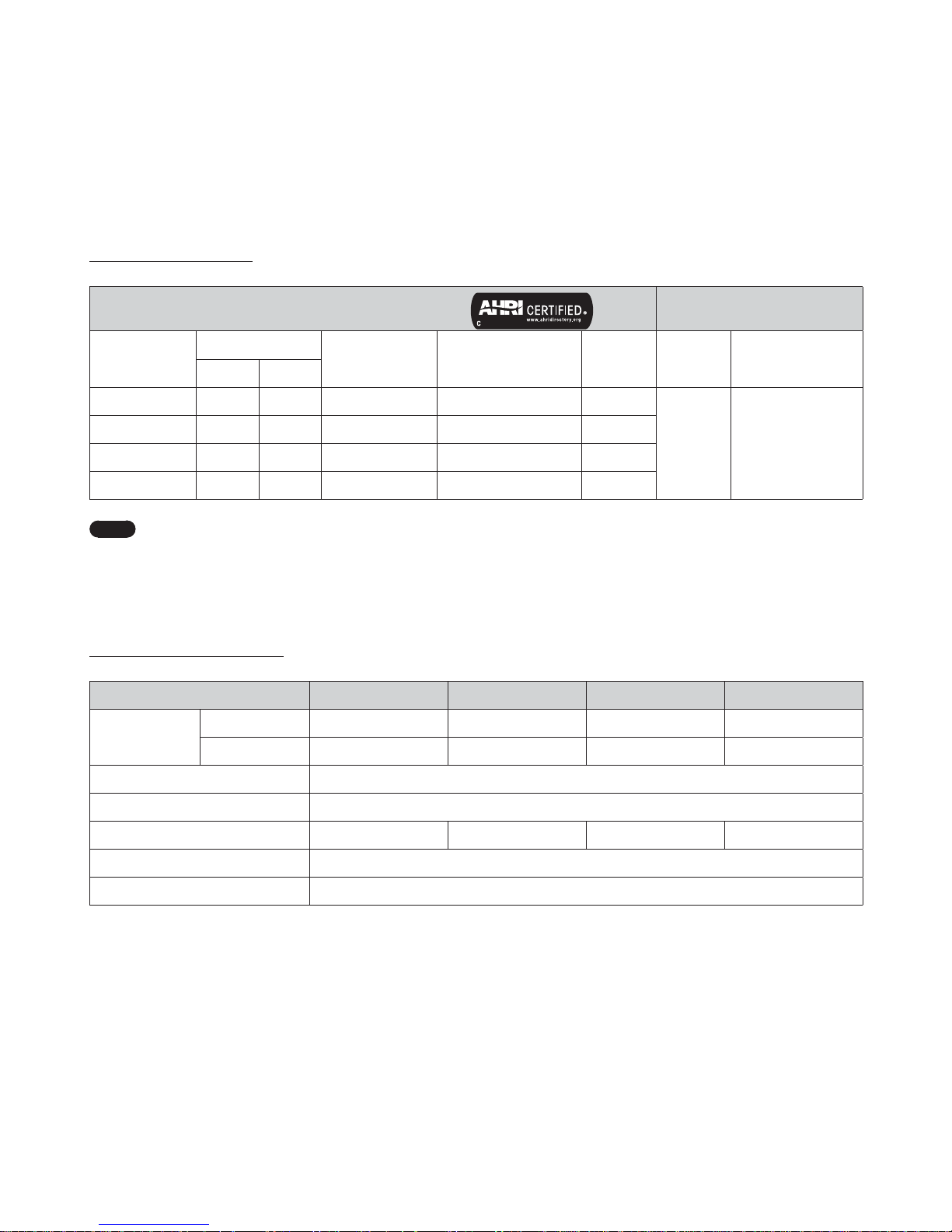
1.3 Specifications
The following tables list the specifications for the boiler. Additional specifications about water, gas, electric, and air supplies (venting) appear in
the Installation section.
Space Heating Specifications
Navien Combination Boiler
Space Heating Ratings
Other Specifications
Model Number
1
Heating Input, MBH
Heating Capacity
2
,
MBH
Net AHRI Rating Water3,
MBH
AFUE
2
, %
Water
Pressure
Water Connection
size (Supply, Return)
Min Max
NCB-150E 12 60 56 49 95
12-30 psi 1 in NPT
NCB-180E 14 80 75 65 95
NCB-210E 18 100 94 82 95
NCB-240E 18 120112 97 95
Note
1. Ratings are the same for natural gas models converted to propane use.
2. Based on U.S. Department of Energy (DOE) test procedures.
3. The net AHRI water ratings shown are based on a piping and pickup allowance of 1.15. Consult Navien before selecting a boiler
for installations having unusual piping and pickup requirements, such as intermittent system operation, extensive piping
system, etc.
Domestic Hot Water Specifications
Item NCB-150E NCB-180E NCB-210E NCB-240E
Input Ratings
Min 12,000 BTU/H 14,000 BTU/H 18,000 BTU/H 18,000 BTU/H
Max 120,000 BTU/H 150,000 BTU/H 180,000 BTU/H 199,900 BTU/H
Water Pressure 15-150 psi
Minimum Flow Rate 0.5 GPM (1.9 L/m)
Flow Rate 77°F (43°C) Temp. Rise 3. GPM 3.4 GPM 4.0 GPM 4.5 GPM
DHW Supply Connection Size
3
/4 in NPT
Cold Water Input Connection Size
3
/4 in NPT
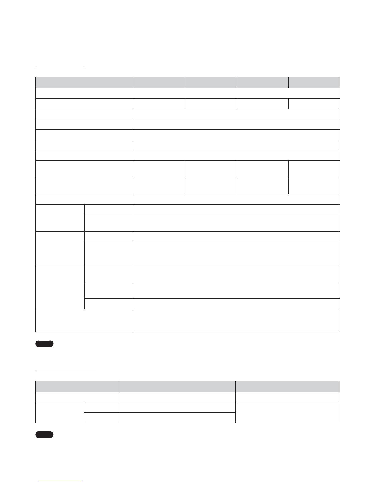
About the Boiler 9
General Specications
Item NCB-150E NCB-180E NCB-210E NCB-240E
Dimensions 17 in (W) x 28 in (H) x 13 in (D)
Weight 66 lbs (30 kg) 74 lbs (34 kg) 84 lbs (38 kg) 84 lbs (38 kg)
Installation Type Indoor Wall-Hung
Venting Type Forced Draft Direct Vent
Ignition Electronic Ignition
Natural Gas Supply Pressure (from source) 3.5 in-10.5 in WC
Propane Gas Supply Pressure (from source) 8.0 in-13.5 in WC
Natural Gas Manifold Pressure (min/max)
-0.09 in WC /
-0.34 in WC
-0.07 in WC /
-0.66 in WC
-0.05 in WC /
-0.36 in WC
-0.06 in WC /
-1.20 in WC
Propane Gas Manifold Pressure (min/max)
-0.04 in WC /
-0.30 in WC
-0.07 in WC /
-0.66 in WC
-0.10 in WC /
-0.66 in WC
-0.03 in WC /
-0.98 in WC
Gas Connection Size
3
/4 in NPT
Power Supply
Main Supply 120V AC, 60Hz
Maximum Power
Consumption
200W (max 2A)
Materials
Casing Cold-rolled carbon steel
Heat Exchangers
Primary Heat Exchanger: Stainless Steel
Secondary Heat Exchanger: Stainless Steel
Domestic Water Heat Exchanger: Stainless Steel
Venting
Exhaust
2 in or 3 in PVC, CPVC, Polypropylene
2 in or 3 in Special Gas Vent Type BH (Class III, A/B/C)
Intake
2 in or 3 in PVC, CPVC, Polypropylene
2 in or 3 in Special Gas Vent Type BH (Class III, A/B/C)
Vent Clearances 0 in to combustibles
Safety Devices
Flame Rod, APS, Gas Valve Operation Detector, Ignition Operation Detector, Water
Temperature High Limit Switch,
Exhaust Temperature High Limit Sensor
Note
This unit may be installed at elevations up to 10,100 ft (3,078 m) for use with Natural Gas, and up to 4,500 ft (1,370 m) for use with
Propane.
Temperature Setting Range
Item Temperature Setting Range Remarks
DHW 89°F-140°F (30°C-60°C)
Space Heating
Supply 120°F-180°F (48.5°C-82°C)
Finned Tube Baseboard (Default)
Return 101°F-147°F (38°C-63.5°C)
Note
For more information about space heating temperature setting range, refer to “Types of Heat Load” on page 58.
10 About the Boiler
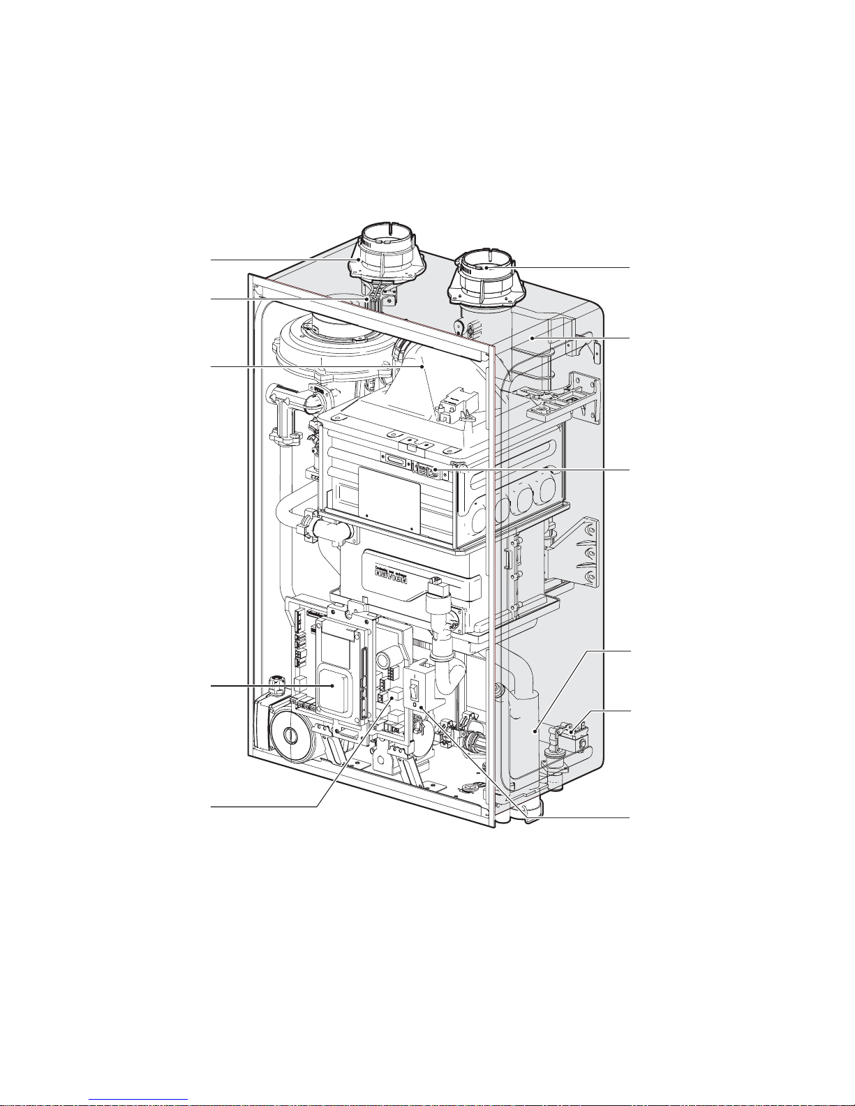
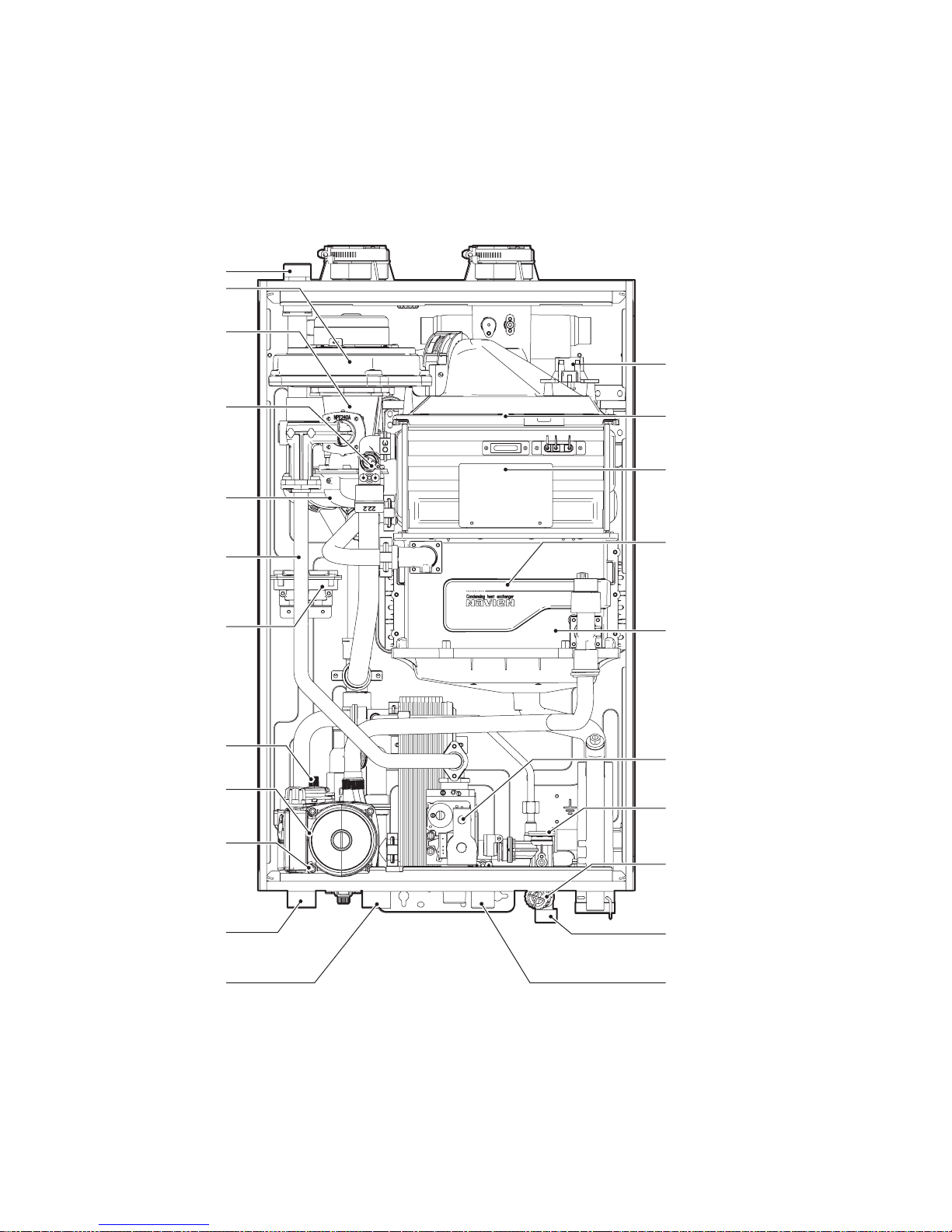
1.4 Components
The following diagram shows the key components of the boiler. Component assembly diagrams and particular parts lists are included in the
Appendixes.
Intake Air
Air Filter
Mixing Chamber
Front Panel
Exhaust
Flue Duct
Ignitor & Flame Rod
Auto Feeder
(Make-up water)
Condensate Trap
PCB
Power Switch
About the Boiler 11
Air Vent
Fan & Motor
Ignition Transformer
Dual Venturi
Premix Burner
Air Pipe
Primary Heat Exchanger
Gas Pipe
Secondary Heat Exchanger
Circulation Pump
Flow Sensor
Pressure Sensor (LWCO)
3-Way Valve
DHW Inlet Filter
(with built-in flow restrictor)
Space Heating
Supply
DHW Inlet
Space Heating
Return
DHW Outlet
Gas Valve
APS
High Limit Switch
Pressure Relief Valve Adapter
12 About the Boiler
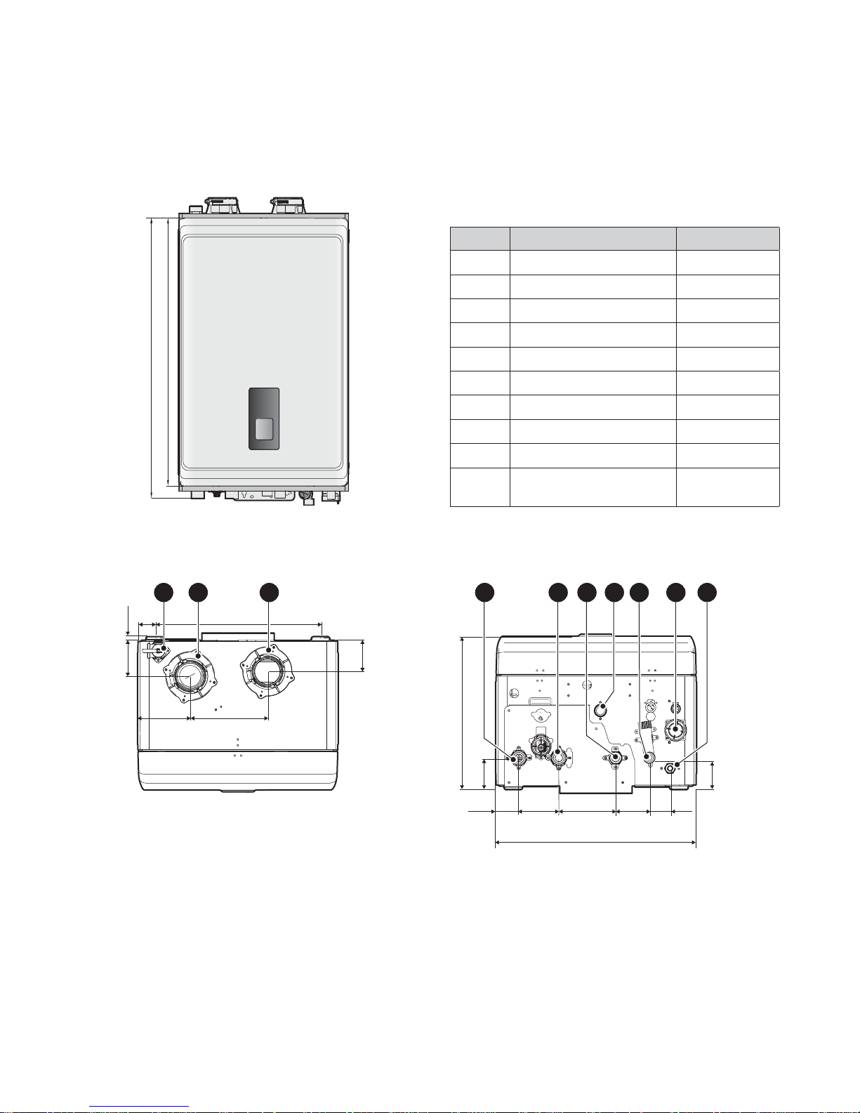
1.5 Dimensions
The following diagrams show the dimensions of the boiler and the table lists the supply connections.
27.4" (695mm)
28.8” (731mm)
Supply Connections
Description Diameter
A Pressure Relief Valve Adapter
3
/4 in
B Air Intake 2 in
C Exhaust Gas Vent 2 in
D Space Heating Supply 1 in
E Space Heating Return 1 in
F Hot Water Outlet (DHW)
3
/4 in
G Gas Supply Inlet
3
/4 in
H Cold Water Inlet (DHW)
3
/4 in
I Condensate Outlet
1
/2 in
J
Auto Feeder Inlet (Make-up
Water)
1
/2 in
Overhead View
3” (77 mm)
6.7” (170 mm)
4.5” (115 mm)
0.4“ (10 mm)
1.5”
(38 mm)
14.3” (364 mm)
2.6” (67 mm)
A
B C
Supply Connections
13“ (330 mm)
3.5”
(88 mm)
4.8”
(123 mm)3”(76 mm)
1.8”
(46 mm)
2”
(50 mm)
17.3” (440 mm)
2.4” (61 mm)
3.0” (77 mm)
D F J
E
H
IG
About the Boiler 13
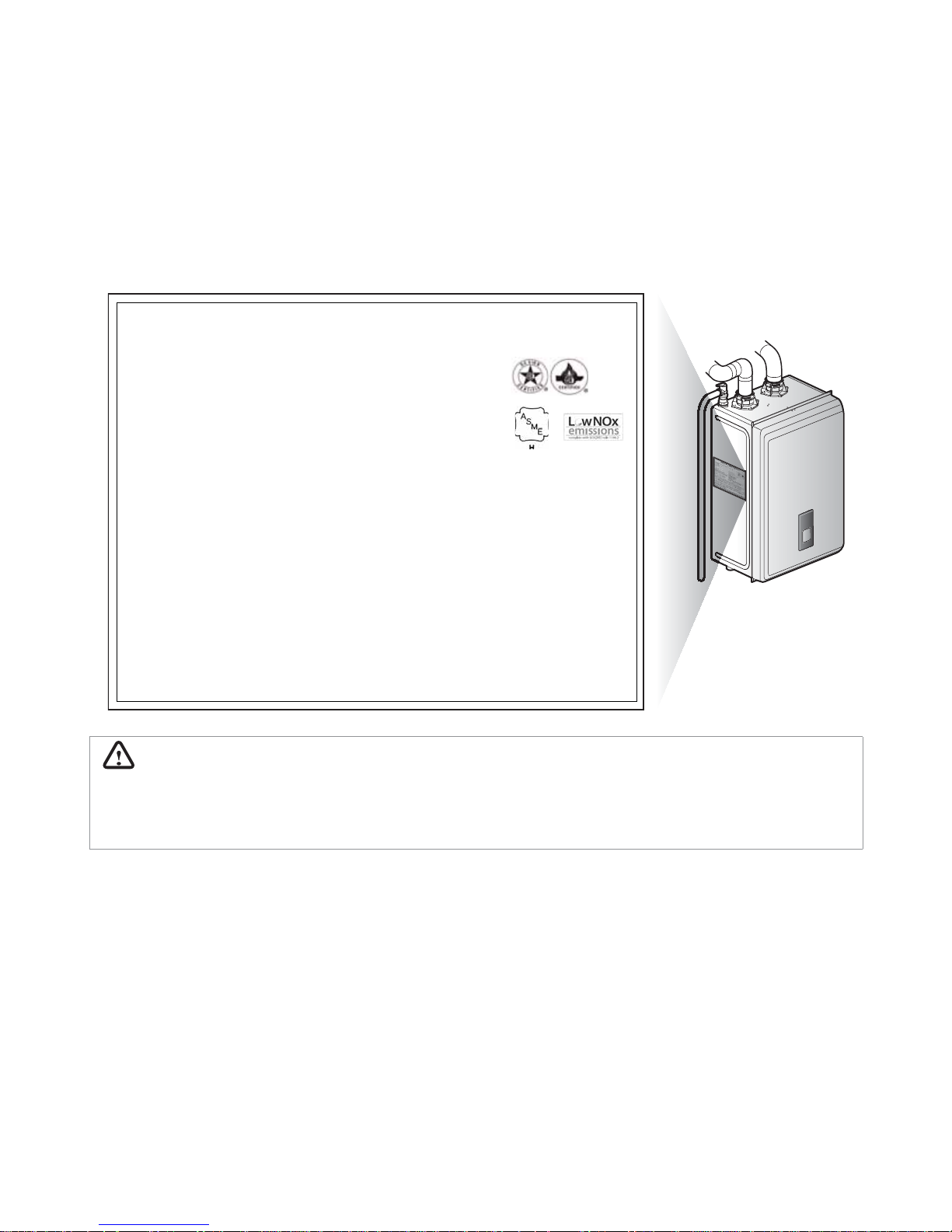
1.6 Rating Plate
The Navien NCB-E boilers come from the factory configured for use with Natural Gas (NG). Before starting the installation, check the rating
plate located on the side of the boiler to ensure that the boiler matches the gas type, gas pressure, water pressure, and electrical supply
available in the installation location. If the boiler does not match each of these ratings, do not install the boiler. If conversion to Propane
Gas is required, the included gas conversion kit must be used. Refer to “11.1 Gas Conversion” for details.
Rating Plate, *Plaque Signalétique
Combination Boiler *Chaudière combinaison
Navien, Inc.
20 Goodyear, Irvine, CA 92618
Tel: 1-800-519-8794
Direct vent indoor installation, * Évacuation directe installation intérieure
Model No., *Numéro de modèle Type of Gas, *Type de gaz
NCB-240E NG
Max. Input Rating (DHW),*Entrée GPL max. Min. Input Rating,*Débit calorifique max.
199,900 Btu/h 18,000 Btu/h
Max. Input Rating (Heating),*Entrée GPL max. Heating Capacity, *Capacité de chauffage
120,000 Btu/h 112,000 Btu/h
Category of boiler, *Catégorie de chaudière Net AHRI Rating, *Régime de AHRI
Category IV 97,000 Btu/h
Max. Inlet Gas Pressure, *Pression max. de gaz d’entrée 10.5 Inches W.C. *pouces W.C.
Min. Inlet Gas Pressure, *Pression min. de gaz d’entrée 3.5 Inches W.C. *pouces W.C.
Manifold Pressure, *Pression d’admiss
ion -1.20 Inches W. C. *pouces W.C.
Electrical Rating, *Régime nominal électrique AC *c.a. 120 Volts 60Hz Use less than 2 Amp, *Utilise moins de 2A
Minimum relief valve capacity, *Capacité minimaum soupape. 189 lbs/hr ANSI Z21.13b-2014 · CSA 4.9b-2014
Orifices necessary for LP conversion are provided. *Les injectures nécessaires à la conversion au GPL sont fournis.
Failure to use the correct gas can cause pro
blems which can result in death, serious injury or property damage. *Le fait de ne pas
utiliser le bon gaz peut causer des problèmes qui peuvent mener à la mort, causer des blessures graves ou endommager la propriété.
Consult your installation manual for more information. *Consultez votre manuel d’installation pour plus d’information.
This appliance is certified for use at altitudes up to 4,500 ft (1,370 m) in accordance to the latest CAN/CGA 2.17-High Altitude
Installation procedures at normal manifold pressure. For installation instructions at altitudes higher than 4,500 ft, please contact
Navien. *Cet appareil est certifié pour une utilisation à des altitudes de 0 à 4,500 pieds (1,370 m) conformément aux toutes les procédures
d’installation à haute altitude CAN/CGA 2.17 à une pression normale. Pour les installations à élévations en haut de 4,500 pieds, appeler le
bureau de Navien.
This appliance must be installed in accordance with local codes or in the absence of local codes, the most recent edition of
National Fuel Gas Code, ANSI Z223. 1, in Canada use CAN/CGA B149. 1 or 2 installation codes for Gas Burning Appliances.
*Cet appareil doit être installé conformément aux codes locaux, ou
s’il n’y a pas de codes locaux, la plus récente version du National Fuel
Gas Code des É.-U., ANSI Z223. 1, au Canada utilisez les codes d’installation CAN/CGA B149. 1 ou 2 pour les appareils à gaz.
FOR YOUR SAFETY *POUR VOTRE SÉCURITÉ
Do not store or use gasoline or other flammable vapors and liquids in the vicinity of this or any other gas appliances. *Ne rangez
pas et n'utilisez pas d'essence ou d'autres liquides ou vapeurs inflammables près de cet appareil ou de tout autre appareil électroménager.
WARNING
Ensure that the gas type and power source specifications match what is listed on the rating plate. Using a different gas type will cause
abnormal combustion and boiler malfunction. Using abnormally high or low AC voltage may cause abnormal operation, and may reduce
the life expectancy of the product.
This appliance complies with the requirements of SCAQMD Rule 1146.2 for NOx emissions of 14 ng/J or 20 ppm at 3% O
2
.

14 Installing the Boiler
2.1 Choosing an Installation Location
When choosing an installation location, you must ensure that the
location provides adequate clearance for the boiler, adequate
venting and drainage options, and sufficient access to gas, water,
and electrical supplies. Carefully consider the following factors
when choosing an installation location:
Compliance Requirements
Ɣ
Local, state, provincial, and national codes, laws, regulations, and
ordinances.
Ɣ
National Fuel Gas Code, ANSI Z223.1-latest edition.
Ɣ
Standard for Controls and Safety Devices for Automatically Fired
Boilers, ANSI/ASME CSD-1, when required.
Ɣ
National Electrical Code.
Ɣ
For Canada only: B149.1 Installation Code, CSA C22.1 Canadian
Electrical Code Part 1 and any local codes.
Access to Utilities
Ɣ
Water – the installation location should be near where the
domestic water supply enters the building.
Ɣ
Gas – the installation location should be near where the gas
supply enters the building.
Ɣ
Electricity – the installation location should be near where the
electrical supply enters the building.
Humidity and Contact with Water
When installing the boiler, avoid places with excessive humidity.
The boiler has electric gas ignition components. Water spray or
droppings can get inside the boiler and damage the ignition
system. The boiler must be installed in a way to ensure that the gas
ignition system components are protected from water (dripping,
spraying, rain, etc.) during operation and service.
Adequate Drainage
The boiler produces a significant amount of condensate during
operation. The boiler should be located near a suitable drain and
where damage from a possible leak will be minimal. Installing
the boiler in a location without a drain will void the warranty and
Navien will not be responsible for water damages that occur as a
result. For more information about condensate drainage, refer to
“3.3 Connecting the Condensate Drain” on page 23.
The boiler must be located in an area where leakage of the unit or
connections will not result in damage to the area adjacent to the
appliance or to lower floors of the structure. When such locations
cannot be found, installation of an adequately drained drain pan
under the boiler is highly recommended. When installing the drain
pan, ensure that the installation does not restrict combustion air
flow.
Adequate Venting and Ventilation
Select a location that requires minimal venting. Consider venting
restrictions caused by windows, doors, air intakes, gas meters,
foliage, and other buildings. For more information about venting,
refer to “6. Venting the Boiler” on page 40.
To ensure adequate venting and ventilation, follow these
guidelines:
Ɣ
Maintain proper clearances from any openings in the building.
Ɣ
Install the boiler with a minimum clearance of 12 in (300 mm)
above an exterior grade or as required by local codes.
Ɣ
Maintain a minimum clearance of 4 ft (1.2 m) from heating and
cooling vents.
Ɣ
Do not enclose the vent termination.
Ɣ
Install the exhaust vent in an area that is free from any
obstructions, where the exhaust will not accumulate.
Ɣ
Do not install the boiler where moisture from the exhaust may
discolor or damage walls.
Ɣ
Do not install the boiler in bathrooms, bedrooms, or any other
occupied rooms that are normally kept closed or not adequately
ventilated.
Proximity to Fixtures and Appliances
Install the boiler near fixtures that deliver or use hot water, such
as bathroom, kitchen, and laundry room faucets. Select a location
that minimizes the water piping required between major fixtures.
If the distances are long or if the user requires “instant“ hot water,
installation of a recirculation line which circulates domestic hot
water back to the boiler from the furthest fixture is recommended.
Insulate as much of the hot water supply and recirculation lines as
possible. For more information about the water supply, refer to "3.2
Installing a Domestic Hot Water (DHW) System” on page 20.
2. Installing the Boiler
Installing the Boiler 15
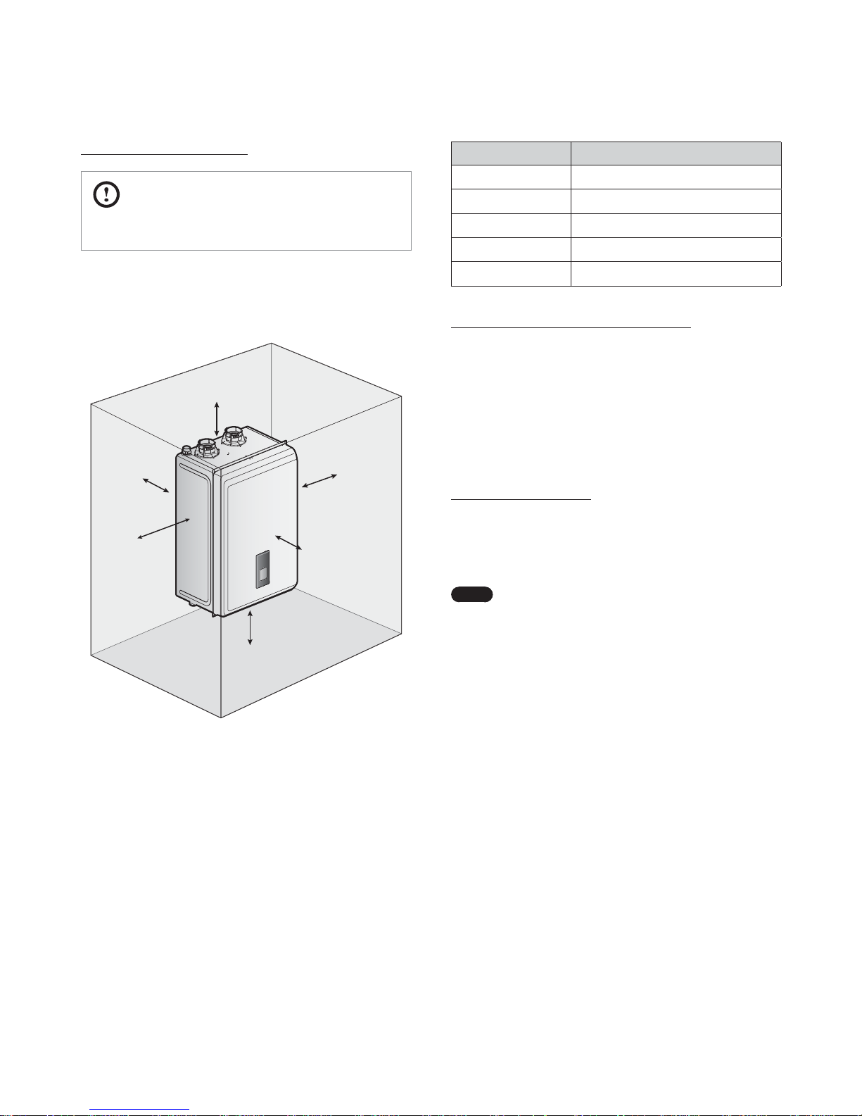
Clearance from: Indoor Installation
Top 9 in (229 mm) minimum
Back 0.5 in (13 mm) minimum
Front 4 in (100 mm) minimum
Sides 3 in (76 mm) minimum
Bottom 12 in (300 mm) minimum
Clean, debris and chemical-free combustion air
Ɣ
Do not install the boiler in areas where dust and debris may
accumulate or where hair sprays, spray detergents, chlorine, or
similar chemicals are used.
Ɣ
Do not install the boiler in areas where gasoline or other
flammables are used or stored.
Ɣ
Ensure that combustible materials are stored away from the
boiler and that hanging laundry or similar items do not obstruct
access to the boiler or its venting.
High Elevation Installations
This boiler may be installed at elevations up to 10,100 ft (3,078 m)
for use with natural gas (NG), and up to 4,500 ft (1,370 m) for
use with liquefied petroleum (LP). Refer to "7. Setting the DIP
Switches" on page 48 for the appropriate altitude setting.
Note
Above 2,000 ft (610m), the boiler will derate by 4% for
each 1,000 ft (300 m) of altitude gain.
Adequate installation clearances
CAUTION
Do not install the boiler on carpeting.
Install the boiler in an area that allows for service and maintenance
access to utility connections, piping, filters, and traps. Based on
the installation location, ensure that the following clearances are
maintained:
Top
Back
Side
Bottom
Front
Side
16 Installing the Boiler
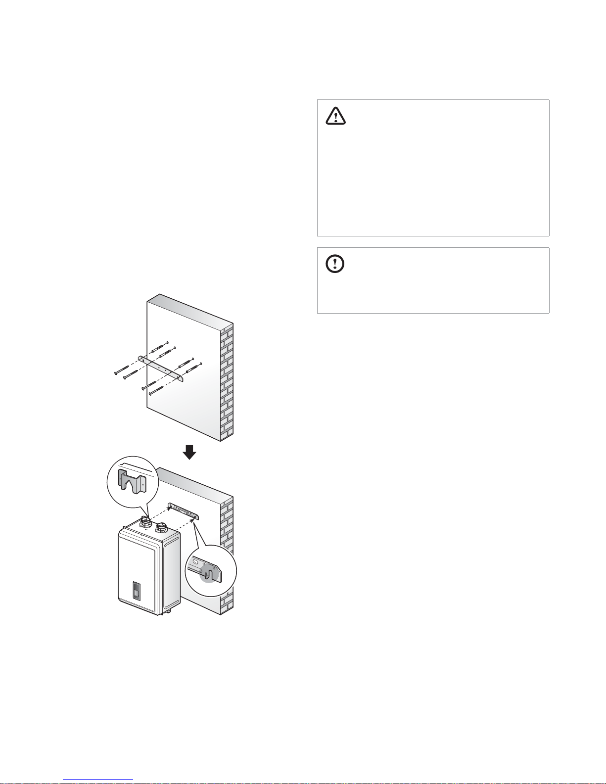
2.2 Mounting the Boiler to the Wall
Navien NCB-E boilers come with an upper mounting bracket that
is pre-drilled at 16 in (400 mm) on center for easy installation on
standard wall studs. If the strength of the wall is insufficient or if
the framing is non-standard or uneven, reinforce the area before
installing the boiler. Avoid installation on common walls as the unit
will make some operational noises while it is running.
To mount the boiler to the wall:
1. Affix the bracket securely to the wall and ensure that it is level
and that it can support the weight of the boiler.
2. Align the grooves on the back of the boiler with the tongues
on the mounting bracket and hang the boiler on the bracket.
When mounted with the mounting bracket, the boiler will
have a
5
/8 in (16 mm) clearance from the back of the wall.
WARNING
Ɣ
The boiler is heavy. Always lift the unit with assistance. Be
careful not to drop the boiler while lifting or handling it to
avoid bodily injury or damage to the unit.
Ɣ
Do not rest the boiler on the bottom end after removing it
from the shipping carton. Doing so may result in excessive
pressure on protruding pipes and cause product damage.
If you must put the boiler down, lay it on its back or put it
inside the protective shipping base.
CAUTION
Do not mount the boiler to dry wall that has not been
reinforced.
Installing the System Piping 17
Prior to connecting plumbing to the boiler, flush the entire system
to ensure it is free of sediment, flux, solder, scale, debris or other
impurities that may be harmful to the system and boiler. During
the assembly of the heating system, it is important to keep the
inside of the piping free of any debris including construction and
copper dust, sand and dirt.
For retrofits, all system piping including radiators, must be cleaned
of all build-up including sludge and scale. All systems, old and new,
must be cleaned to remove flux, grease and carbon residue. Navien
recommends cleaning the boiler system with cleaning products
specially formulated for boiler systems. For retrofit applications
with heavy limescale and sludge deposits, a heavier duty cleaner
may be required. For information on performing the cleaning,
follow the instructions included with the boiler system cleaner
products.
WARNING
Failure to rid the heating system of the contaminants listed
above will void your warranty and may result in premature
heat exchanger failure and property damage.
3.1 Installing a Space Heating System
The primary and secondary heat exchangers of the Navien NCB-E
boiler are designed to attain the highest level of heat transfer in
a compact design. To accomplish this, the heating water flows
through a series of tubes (secondary heat exchanger) and finned
tubes (primary heat exchanger), designed to maximize the heat
transfer area. To maintain the efficient and reliable operation of the
heat exchangers, and to avoid heat exchanger failure, it is critical to
ensure the rules and guidelines in this section are followed.
CAUTION
Failure to follow the instructions provided in this section will
void the warranty and may result in property damage, fire,
serious injury or death.
3. Installing the System Piping
3.1.1 Guidelines for a Space Heating Installation
Read and follow the guidelines listed below to ensure safe and
proper installation of a boiler heating system.
Freeze Protection for a Space Heating System
Ɣ
Freeze protection products may be used for the space heating
system. Freeze protection for new or existing systems requires
specially formulated glycol , which contains inhibitors to prevent
the glycol from attacking the metallic system components.
Ɣ
Before using freeze protection products, ensure that system
fluid contains proper glycol concentration and the inhibitor level
is appropriate. Navien recommends against exceeding a 35%
concentration of glycol.
Ɣ
When using the freeze protection products, the system must
be tested at least once a year, and as recommended by the
manufacturer of the glycol solution.
Ɣ
When using the freeze protection products, allowance should be
made for expansion of the glycol solution.
Ɣ
Freeze damage is not covered by the warranty.
WARNING
For systems requiring freeze protection, use only inhibited
propylene glycol, specially formulated for hydronic heating
systems; use of other types of antifreeze may be harmful to the
system and will void the warranty.
System Pressure
Ɣ
The Navien NCB-E boiler is intended solely for use in pressurized
closed loop heating systems operating with 12-30 psi water
pressure at the boiler outlet. To obtain the minimum system
design pressure, follow the piping diagrams illustrated in this
section.
Ɣ
The Navien NCB-E boiler’s space heating system is not approved
for operation in an “open system”, thus it cannot be used for
direct potable water heating or to process heating of any kind.
18 Installing the System Piping
Oxygen Elimination
This boiler may only be installed in a pressurized closed-loop
heating system, free of air (oxygen) and other impurities. To avoid
the presence of oxygen, ensure all of the air is removed from
the system during commissioning via strategically placed and
adequately sized air removal devices, located throughout the
heating system.
Note
Ɣ
The Navien NCB-E boiler has a built-in air vent on top
of the internal circulator to efficiently remove the air in
the space heating system.
Ɣ
See the examples of system application at the end of
this section detailing the installation location of the
air removal device, in case an additional air removal
device is required for a specific application.
WARNING
Ɣ
Immediately repair any leaks in the system plumbing to
avoid the addition of make-up water; make-up water
provides a source of oxygen and minerals that may lead to
heat exchanger failure.
Ɣ
Failure to follow these instructions will result in poor
performance, unnecessary wear of system components and
premature failure.
3.1.2 Essential Elements in a Space Heating System
Low Water Cut Off (LWCO) Device
Internal LWCO
The Navien NCB-E boiler is equipped with a factory-installed,
pressure-sensing type low water cutoff (LWCO) device. The
minimum operation pressure for this device is 7.3 psig.
Note
Ɣ
The boiler performs water replenishment
automatically when the built-in water pressure sensor
detects insufficient water level in the boiler system.
Ɣ
If the water replenishment is not completed after
5 minutes, error code E351 is displayed on the front
panel requiring a manual boiler reset.
Refer to local codes to determine if a LWCO device is required
for your system and ensure that the built-in device meets the
requirements. Install a backflow preventer in the make-up water
line to the unit if required by local codes.
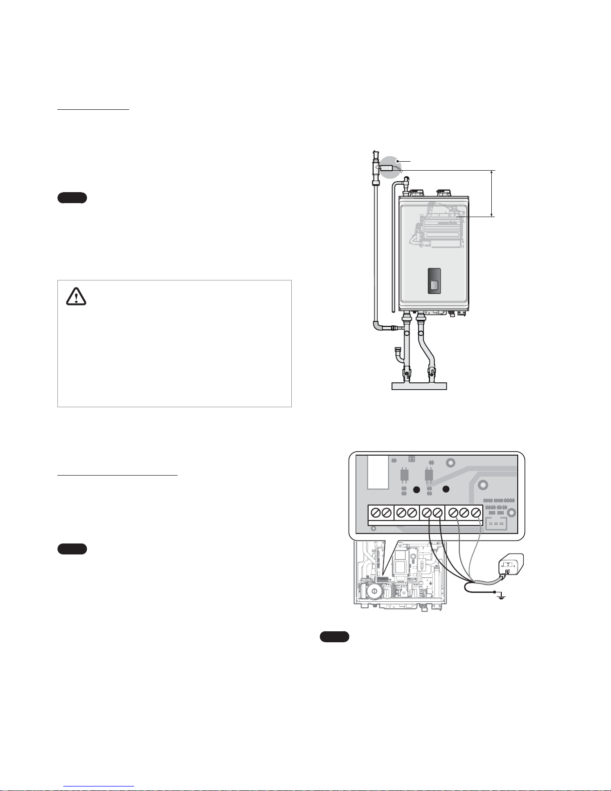
External LWCO
Install a separate LWCO device if required by local codes. The
following figure illustrates an example of typical LWCO installation.
External LWCO
6" (152 mm) min.
The external LWCO must be installed at least 6 in (150 mm) above
the top of the heat exchanger. Refer to the following diagram for
typical wiring connections of the LWCO to the boiler PCB.
CN23 CN10 CN24 CN25
Common Hot
Note
Ɣ
Remove the factory installed jumper on the LWCO
terminals (CN24) prior to connecting the LWCO.
Ɣ
The boiler supplies 24 VAC at the LWCO power
terminals (CN25).
Installing the System Piping 19
Backflow Preventer
Install a backflow preventer valve in the make-up water supply to
the unit as required by local codes.
Expansion Tank
An expansion tank must be installed in the space heating piping
to prevent excessive pressure from building in the system. See the
examples of system application at the end of this section for the
installation location. Refer to the expansion tank manufacturer’s
instructions for additional details.
Follow the guidelines below when installing an expansion tank.
Ɣ
Connect an air separator to the expansion tank only if the air
separator is located on the suction side of the system circulator.
Ɣ
Navien NCB-E boiler is equipped with an auto-feeding water
connection and motorized feeding valve. Therefore, installation
of additional system water fill connection is not necessary in
most cases.
Ɣ
If an additional water fill connection is required for a specific
use, install the water fill connection at the same location as the
expansion tank’s connection to the system.
Ɣ
When replacing an expansion tank, consult the expansion tank
manufacturer’s literature for proper sizing.
Ɣ
For diaphragm expansion tanks, always install an automatic air
vent on the top side of the air separator to remove residual air
from the system.
Isolation Valves and Unions
Ɣ
Full port ball valves are required for the boiler system. Failure
to use full port ball valves could result in a restricted flow rate
through the boiler.
Ɣ
Check valves are recommended for installation. Failure to install
check valves could result in a reverse flow condition during
pump(s) off cycle.
Ɣ
Unions are recommended for unit serviceability.
Pressure Relief Valve
To complete the space heating system installation, you must install
a
3
/4 in, maximum 30 psi pressure relief valve to the pressure relief
valve adapter located on the top side of the NCB-E boiler. An ASME
approved HV pressure relief valve for space heating system is
supplied with the boiler.
WARNING
Ɣ
Installing the pressure relief valve improperly may result
in property damage, personal injury, or death. Follow all
instructions and guidelines when installing the pressure
relief valve. The valve should be installed only by a licensed
professional.
Ɣ
The pressure relief valve must be installed vertically to the
pressure relief valve adapter on the top side of the boiler,
as shown in the example below, with the drain pipe outlet
exiting the side of the pressure relief valve horizontally and
elbowing down.
CAUTION
Install the pressure relief valve as close to the boiler as possible.
No other valve should be installed between the pressure relief
valve and boiler.
Refer to the following illustration and install a pressure relief valve
to the pressure relief valve adapter located on the top corner of the
NCB-E boiler. Conbraco Watts M330-M1 pressure relief valve (
3
/4 in,
HV, Max 30 psi) is provided with the boiler.
Pressure
Relief Valve
20 Installing the System Piping
When installing the pressure relief valve, follow these guidelines:
Ɣ
Ensure that the valve’s discharge capacity is equal to or greater
than the maximum pressure rating of the boiler’s space heating
system.
Ɣ
Ensure that the maximum BTU/H rating on the pressure relief
valve is equal to or greater than the maximum input BTU/H
rating of the boiler.
Ɣ
Direct the discharge piping of the pressure relief valve so
that hot water does not splash on operator, or any nearby
equipment.
Ɣ
Attach the discharge line to the pressure relief valve and run the
end of the line to within 6-12 in (150-300 mm) of the floor.
Ɣ
Ensure that the discharge line allows for free and complete
drainage without restriction. Do not install a reducing coupling
or other restrictions on the discharge line.
If the relief valve discharges periodically, this may be due to
thermal expansion caused by expansion tank waterlogging or
undersizing. Do not plug the relief valve.
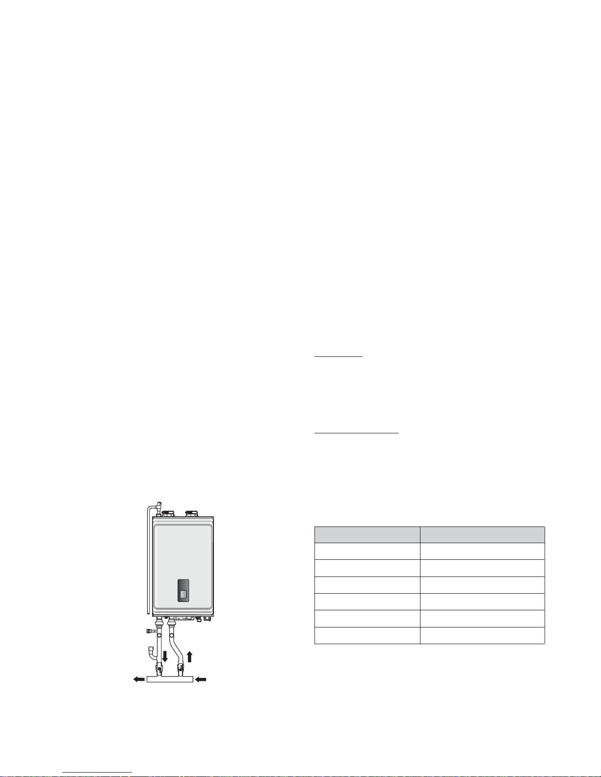
3.1.3 Space Heating System Piping
When connecting the space heating system, follow these
guidelines:
Ɣ
Tighten the connection valves with care to avoid damage.
Ɣ
After installing the boiler, clean the strainer for space heating
return. Then, test the boiler for proper space heating flow and
inspect for leaks. Instruct the boiler owner that the strainer must
be cleaned periodically to maintain proper space heating water
flow.
The Navien manifold system (optional) allows for easy separation
of the Boiler-Primary loop from the System-Secondary loop(s).
Refer to the following illustration for a typical water piping
example with a Navien manifold system.
Space Heating
Return
Space Heating
Supply
3.2 Installing a Domestic Hot Water (DHW)
System
The Navien NCB-E boiler provides domestic hot water continuously
when flow is sensed by the flow sensor. This method is the most
efficient means of heating water by allowing the boiler to operate
at a lower return water temperature by minimizing standby losses,
thus increasing combustion efficiency.
3.2.1 Guidelines for a DHW System
With its multi-purpose design, the Navien NCB-E boiler provides
hot water on demand. This means that the boiler produces DHW
only when the user demands it.
The boiler recognizes a DHW demand when the flow sensor
detects a DHW flow of approximately 0.5 GPM or greater. Once
the flow sensor detects the flow, the boiler immediately goes into
DHW mode regardless of the status of the space heating system.
Read and follow the guidelines listed below to ensure safe and
proper installation of a boiler heating system.
Scald Hazard
Hotter water increases the risk of scald injury. There is a hot water
scald potential if the DHW temperature is set too high. Be sure
to follow the adjustment instructions in the boiler’s operation
manual.
About the DHW Quality
Proper maintenance of the boiler is required to ensure that your
DHW meets EPA quality standards. The following table shows the
maximum contaminant levels allowed, based on the EPA National
Secondary Drinking Water Regulations (40 CFR Part 143.3). If you
suspect that your water is contaminated in any way, discontinue
use of the DHW and contact an authorized technician or licensed
professional.
Contaminant Maximum Allowable Level
Total Hardness Up to 200 mg/l (12 grains/gallon)
Aluminum 0.05 to 0.2 mg/l
Chloride Up to 250 mg/l
Copper Up to 1.0 mg/l
Iron Up to 0.3 mg/l
Manganese Up to 0.05 mg/l
Installing the System Piping 21
Contaminant Maximum Allowable Level
pH 6.5 to 8.5
Sulfate Up to 205 mg/l
Total Dissolved Solids (TDS) Up to 500 mg/l
Zinc Up to 5 mg/l
Navien is not responsible for plugging of the domestic system by
scaling or accumulation of dirt; suitable steps shall be taken by the
installer and user to avoid water quality related issues.
Freeze Protection
Navien recommends heat tracing and insulating the DHW water
pipes. Pipe enclosures may be packed with insulation for added
freeze protection. Freeze damage is not covered by the warranty.
3.2.2 Essential Elements in a DHW System
DHW Heat Exchanger
The DHW heat exchanger installed inside the Navien NCB-E boiler
has been tested and certied in accordance with IAPMO standard
PS 92-2010.
Drain and Isolation Valves
Install drain and isolation valves on the inlet and outlet of the
DHW heat exchanger, so it can be ushed free of possible build-up
caused by dirt or hard water.
DHW Filter
The Navien NCB-E boiler has built-in DHW lter at the entrance of
the cold water inlet. Clean the lter periodically to ensure that the
lter is not obstructed creating disturbance in the ow. Failure to
protect the ow sensor from dirt and debris will cause the boiler to
malfunction.
Flow Restrictor (pressure regulator)
A ow restrictor is used to avoid excessive ow at the faucets. The
Navien NCB-E boiler has a built-in ow restrictor at the cold water
inlet adapter to limit the overall ow of domestic hot water. Follow
the instructions below when installing a ow restrictor:
CAUTION
Do not operate the boiler without the ow restrictor installed.
Refer to the ow restrictor specications and install an
appropriate valve for proper operation.
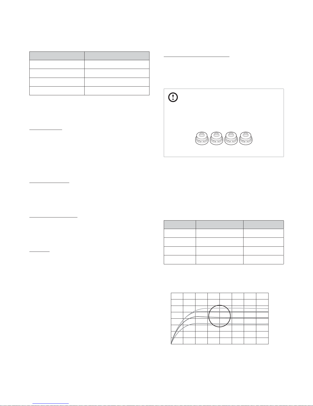
All Navien NCB-E boilers are shipped from the factory with three
ow restrictors included for dierent ow rates. Each ow restrictor
allows for a specied amount of water to ow through the unit. A
ow restrictor valve is pre-installed at the cold water inlet adapter
(at the tip of the cold water inlet lter).
The ow restrictors are color coded for easier identication. Refer
to the table below for detailed specication. Factory-installed ow
restrictors and specications are as follows:
Valve color Applied Model Specication*
Orange NCB-240E, pre-installed 5.6 GPM
Yellow NCB-210E, pre-installed 5.0 GPM
Blue NCB-180E, pre-installed 4.0 GPM
Pink NCB-150E, pre-installed 3.2 GPM
* Flow rate in GPM, as factory tested with 56 psi water pressure.
The following graph describes the water ow rate (in GPM) and
water pressure (in psi) specications for each ow restrictor.
Orange
Yellow
Blue
Pink
8.0
7.0
6.0
5.0
4.0
3.0
2.0
1.0
0.0
0 14 28 42 56 71 85 99
113

22 Installing the System Piping
If necessary, replace the factory-installed flow restrictor with one
that satisfies your flow requirements. Follow these instructions to
replace the flow restrictor.
1. Locate the cold water inlet adapter on the bottom of the unit.
2. Turn the knob counterclockwise to remove the water inlet
filter. The flow restrictor is attached at the tip of the filter
assembly.
3. Remove the current flow restrictor and replace it with one that
provides an appropriate flow rate.
Pressure Relief Valve for DHW
To complete the installation of the DHW system, you must install
an approved
3
/4 in, maximum 150 psi pressure relief valve on
the hot water outlet. The Navien NCB-E boiler has a built-in high
temperature shut off switch, so install a “pressure only“ relief valve.
WARNING
Ɣ
Installing the pressure relief valve improperly may result
in property damage, personal injury, or death. Follow all
instructions and guidelines when installing the pressure
relief valve. The valve should be installed only by a licensed
professional.
Ɣ
The pressure relief valve must be installed at the boiler outlet
and in the vertical position, as shown in the example below,
with the drain pipe outlet exiting the side of the pressure
relief valve horizontally and elbowing down.
The DHW pressure relief valve is not supplied, but is required.
The following examples are pressure relief valves approved for use
with the boiler:
Ɣ
Wilkins P-1000A (Zurn Industries)
Ɣ
Conbraco 17-402-04
Ɣ
Watts Industries 3L (M7)
Ɣ
Cash Acme FWL-2, 3/4 in
Cold Water InletDHW Supply
Pressure
Relief Valve
CAUTION
Install the pressure relief valve as close to the boiler as possible.
No other valve should be installed between the pressure relief
valve and boiler.
Installing the System Piping 23
When installing pressure relief valve, follow these guidelines:
Ɣ
Ensure that the valve’s discharge capacity is equal to or greater
than the maximum pressure rating of the boilers DHW system.
Ɣ
Ensure that the maximum BTU/H rating on the pressure relief
valve is equal to or greater than the maximum input BTU/H
rating of the boiler.
Ɣ
Direct the discharge piping of the pressure relief valve so
that hot water does not splash on operator, or any nearby
equipment.
Ɣ
Attach the discharge line to the pressure relief valve and run the
end of the line to within 6-12 in (150-300 mm) of the floor.
Ɣ
Ensure that the discharge line allows for free and complete
drainage without restriction. Do not install a reducing coupling
or other restrictions on the discharge line.
Ɣ
If the relief valve discharges periodically, this may be due to
thermal expansion in a closed water supply system. Contact the
water supplier or local plumbing inspector on how to correct the
situation. Do not plug the relief valve.
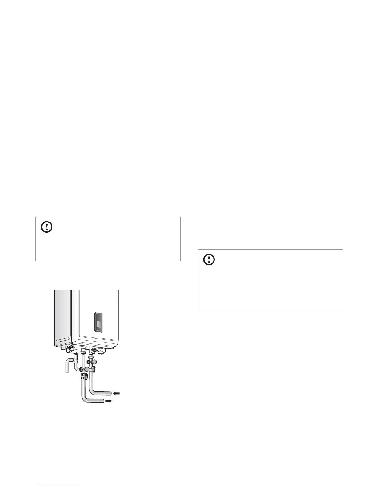
3.2.3 DHW System Piping
CAUTION
To comply with ASME or CRN requirements, an additional high
temperature limitation device may be needed. Consult your
local code requirements to determine if this device is required.
Refer to the following illustration for a typical DHW piping example
for the boiler.
DHW Supply
Cold Water Supply
When installing the DHW system, follow these guidelines:
Ɣ
Use only pipes, fittings, valves, and other components (such as
solder), that are approved for use in potable water systems.
Ɣ
Tighten the connection valves with care to avoid damage.
Ɣ
Navien recommends using unions and manual shut-off valves
on the cold water inlet and DHW outlet.
Ɣ
Keep the hot water piping system as short as possible, to deliver
hot water to the fixtures more quickly.
Ɣ
To conserve water and energy, insulate the DHW supply and
DHW recirculation lines (if applicable). Do not cover the drains or
pressure relief valves.
Ɣ
After installing the boiler, clean the cold water inlet filter.
Then, test the boiler for proper DHW supply and inspect for
leaks. Instruct the boiler owner that the filter must be cleaned
periodically to maintain proper DHW flow.
3.3 Connecting the Condensate Drain
The Navien NCB-E boiler creates condensation when it operates.
This condensation has an acidic pH of 3-5. Follow all local codes
and regulations when disposing of condensate from the boiler.
We recommend draining the condensate into a laundry tub,
as the alkali in laundry detergent will neutralize the acid in the
condensate. However, other suitable waste drain locations may be
used according to the local codes.
CAUTION
Ɣ
Do not cap or plug the integrated condensate line. If
prevented from draining, condensate can damage the boiler.
Ɣ
The condensate line must have a negative slope to drain
properly.

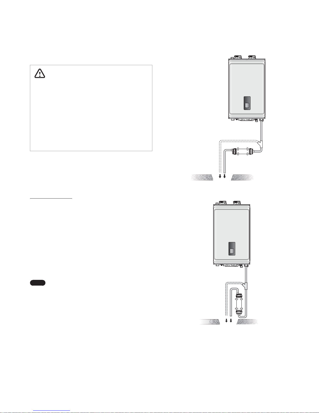
24 Installing the System Piping
Before connecting the condensate drain, choose one of the
following disposal options:
a. From the boiler directly into an external drain
b. From the boiler, through a neutralizing agent, and then
into an external drain
Note
If you choose this option, the neutralizing agent
must be replaced periodically. Depletion of
the neutralizing agent will vary, based on the
usage rate of the boiler. During the first year of
operation, the neutralizer should be checked
every few months for depletion and replaced as
needed.
c. From the boiler into a laundry tub.
Note
The bottom of the boiler must be higher than
the top of the laundry tub to use this option. The
condensate line must have a negative slope to
drain properly.
d. From the boiler into a condensate pump, and then into a
laundry tub.
Note
A pump can be used when there is a long
distance between the boiler and the laundry tub
or when the bottom of the boiler is lower than the
top of the laundry tub.
To connect the condensate drain:
1. Connect a drain line to the
1
/2 in fitting at the bottom of the
boiler.
Use only corrosion-resistant material for the drain line, such as
PVC or CPVC. Do not reduce the size of this fitting or the drain
line to less than
1
/2 in.
NPT / in
2. Place the free end of the drain line into an appropriate drain.
3. If you are using a condensate pump, ensure that the pump
allows for up to 2 GPH of drainage for each boiler in the
system.
4. If you are not using a condensate pump, ensure that the drain
line is pitched downward at a minimum slope of
1
/4 in per foot.
Installing the System Piping 25
3.3.1 Condensate Neutralizer Kit
WARNING
Ɣ
To avoid damaging the appliance, the neutralizer inlet and
discharge must be lower than the condensate drain.
Ɣ
Do NOT allow exhaust flue gases to vent through the
neutralizer. Leakage can cause injury or death from carbon
monoxide.
Ɣ
The connection between the appliance and the neutralizer
must be installed to prevent the backflow of condensate
into the appliance.
Ɣ
Do not connect more than one appliance to the neutralizer.
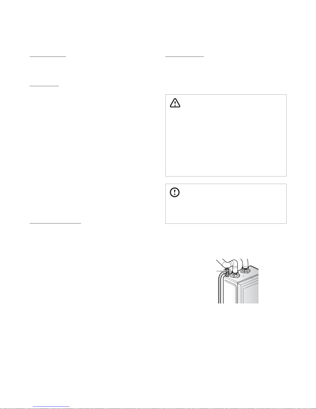
If option 'b' is selected for condensate disposal, the Navien
condensate neutralizer kit is recommended. The condensate from
the appliance flows through the neutralizing media and increases
the pH of the condensate. An increased pH prevents corrosion of
the installation's drainage system and the public sewer system.
Installation guidelines
Ɣ
The inlet has a center connection port and the outlet has an
offset connection.
Ɣ
Install the neutralizer on the wall or the floor and secure it using
the brackets supplied with the kit.
Ɣ
If the neutralizer is installed horizontally, rotate the neutralizer to
position the outlet at the highest point (Figure 1).
Ɣ
If the neutralizer is mounted vertically, ensure that the outlet is
higher than the inlet (Figure 2).
Ɣ
Ensure that the condensate runs freely to the drain.
Ɣ
Ensure all connections are made to prevent the backflow of
condensate. Use corrosion resistant piping and secure all piping
to prevent movement.
Note
Do not install condensate piping in areas where the
temperature drops below freezing point. Protect
piping in high pedestrian areas from damage and
vibration.
Ɣ
For increased safety when the condensate drain blocks, install
a Y-fitting. Connect the Y-fitting as shown in the installation
diagram and ensure that the condensate runs freely to the drain.
Ɣ
Ensure that the discharge connection is accessible. Access to
the discharge connection is required for maintenance and pH
testing.
Ɣ
If there is insufficient gradient for drainage, install a drainage
pump designed for boiler and water heater condensate removal.
Optional
overflow bypass
Figure 1. Horizontal installation
Optional
overflow bypass
Figure 2. Vertical installation
 Loading...