

Installation Manual
Add-on Board Installation Kit
For NPE-180A/210A/240A
This device is designed to work with
NPE-180A/210A/240A models ONLY.
WARNING
All Installations should be done only by a qualied expert and in accordance
with the appropriate Navien manual. Installing an electric appliance with
improper methods or materials may result in serious injury or death due to re.
ELECTRICAL SHOCK HAZARD. Disconnect power before installing or servicing.
Otherwise, electrical shock may result causing severe personal injury, death, or
substantial property damage.
All wiring must be insta lled in accordance with local regulations of the
installation site.
NPE-ODC
1.2 Specications
Refer to the following table for product specications.
Items Specications
Model name
Device type
Add-on input board for Navien NPE-180A/210A/240A
water heaters for HotButton Recirculation
Installation type
Snap-on
(onto the NPE-180A/210A/240A water heater PCB tray)
Connections
Main connector socket to water heater
Main control connector (13-p in cable)
Switch terminal*
Contacts for multiple push button switches
* Push button switches do not require a power source. Multiple switches may be
* SIGNAL1 contacts are for optional wireless push buttons or motion sensor accessories.
** SENSOR I contacts are connected with a piece of metal plate by default. Remove
the metal plate before connecting a temperature sensor to the circuit board.
installed in parallel to activate DHW recirculation from various locations.
1.3 Device Layout
Refer to the following diagram for the product layout.
1.3.1 Wiring Connection Table
Terminal Wiring Connection
Signal1
12 V
Signal
GND
Signal2
(Not polarity sensitive)
Push Button Switch Contact #1
Push Button Switch Contact #2
Sensor I
2. Installing the Device
This section provides information required to install the HotButton Kit in an NPE-180A/210A/240A water heater.
WARNING
Ensure that you have turned o the power to the water heater before installing the device.
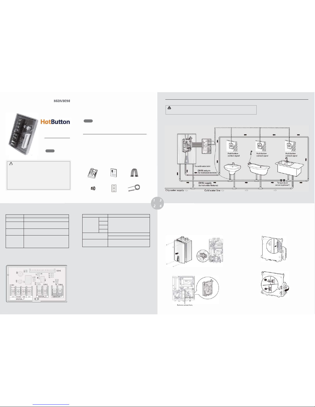
2.1 Basic Principles
The following diagram shows the basic operation of an NPE-180A/210A/240A water heater recirculation system with the HotButton Kit.
2.2 Installing the Device in an NPE-180A/210A/240A
Water Heater
Follow the instructions to install the HotButton Kit in an NPE-
180A/210A/240A
water heater.
1. Turn o the power supply to the water heater.
2. Remove the water heater’s front cover by loosening the four screws securing it
to the case.
4. Remove
the two screws holding the PCB tray in place and pull out the PCB tray
from the unit.
3. Make sure that the 2-way valve is turned to the EXTERNAL setting, once the
plumbing system is completely installed. .
4.
Verify the current PCB version of the NPE water heater.
y
For OLD PCB Version KDC-330-5M P12
: The PCB must be re placed with an
updated version. Remove all the cables and connectors from the PCB and
replace with the latest PCB version that is compatible with the HotButton
Kit. Reconnect all the cables and connectors to the PCB. Proceed to the next
step.
y
For NEW PCB Version KDC-330-5M P20
: The existing PCB can be used. Pull
out the PCB from the tray, but do NOT disconnect any cables or wires.
Proceed directly to t he next step.
5. Install the HotButton Kit onto t he NPE-180A/210A/240A water heater’s PCB
tray. Align the latch at the back of the case with the front lip of the PCB tray.
6. Align the two latches at the back of the HotButton Kit with the two catch
bars at the back of the water heater’s PCB tray. Then pivot the HotButton Kit
onto the PCB tray until the latches snap-on to the catch bars.
7.
Connect cables to the HotButton Kit.
For more details, refer to
“
3. Wiring The Device.
”
When Installing this Product:
1. Read these instructions carefull y. Failure to comply could damage the
product or cause a hazardous condition.
2. Check the ratings provided in the instructions and on the product to make sure the
product is suitable for the application.
3. Installe rs must be trained, experienced, and li censed service tech nicians.
4. Follo w local codes for i nstallation and a pplication requirements.
After the installation
is complete, verify proper operation of this productby following the
instructions provided in this manual.
All wiring must be installed in accordance with local codes and regulations.
This accessory will not operate in conjunction with the Navien H2Air system.
Note
1. About the HotButton Kit
The Navien HotButton Kit is an add- on input board for the Navien NPE-
180A/210A/240A
water heaters. It adds signal input functions to the NPE-
180A/210A/240A
water heaters for
more ecient DHW hot water recirculation functionality.
With the HotButton Kit, DHW recirculation is carried out exactly when the actual
demands arise. This prevents energy loss caused by unnecessary operation of the burner
and pump throughout the day.
The HotButton Kit receives signals from multiple push buttons installed in various
areas and performs opti mal DHW recirculation only when there
is a demand for
1.1 Included Items
The product is supplied with the following items.. Make sure that the installation kit
contains all the items befo re installing the product.
Main Connector - 13-pin to
Navien NPE 180A/210A/240A
Water Heaters
Installation Manual
Navien HotButton Kit
Wall Plate
(#GXXX001427)
Temperature Sensor
(#GXXX001640)
Push Button Switch
(#GXXX001426)
hot water.
Contacts for wireless push button or motion sensor
connection
Contacts for temperature sensor connection
5 V
Note
This device is not compatible with
cascade (multi-unit) installations.
Note
* When the optional temperature sensor is installed, it must be insulated.
The sensor wire may be extended by up to 100 ft (30m) using 22AWG wire.
Add-On Controller
Navien, Inc.
20 Goodyear lrvine, CA 92618
TEL +949-420-0420 FAX +949-420-0430
www.navien.com
8. Replace the PCB tray back into the water heater and secure it with the two
screws.
9. Close the front cover and secure it with the 4 screws.
CAUTION
Before disconnecting cables inside the unit, label all cables. Wiring errors can
cause improper operation and dangerous situations. Verify wiring connections
and unit operation after servicing.
3. Wiring the Device
This section provides information required to plan and install the system wiring.
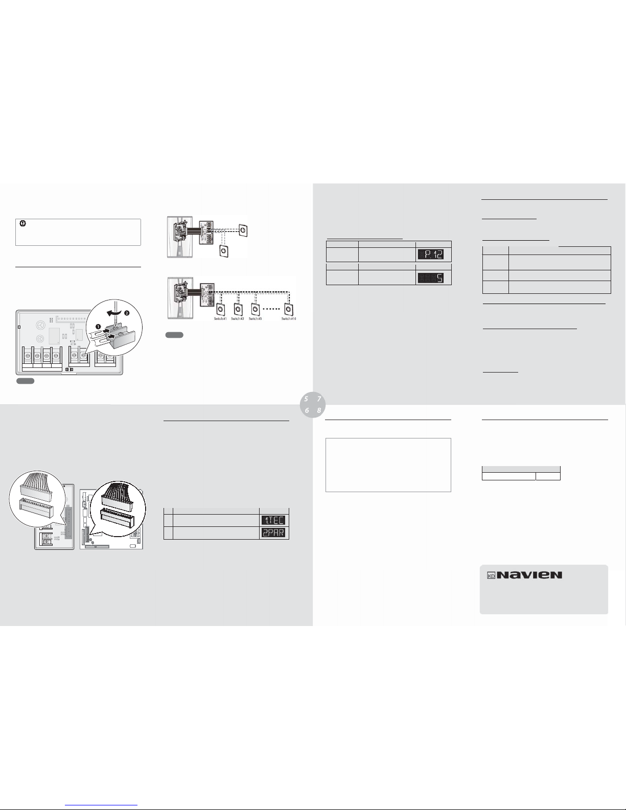
3.1 Connecting Wired Switches
Navien HotButton Kit provi des terminal c ontacts for wire d switch applications.
Refer to the following diagrams to connect a wired switch, or multiple wired
switches to the HotButton controller.
Use UTP cables or cables with a diameter greater than AWG 24.
y
Make sure that the total cable length does not exceed 328 feet (100 meters).
y
Additional push button switches (#GXXX001426) and wall plates (#GXXX001427) can be
purchased through Navien.
y
You can connect up to 10 push button switches to one HotButton controller.
y
Use spade connectors at the end of the cables to securely install the cables to
y
Multiple wired switches may be connected to the same terminal contacts.
y
the terminal contacts.
Note
Note
3.2 Connecting the Main Control Connector
To connect the HotButton Kit to the Navien NPE -180A/210A/240A water heaters, use
the 13-pin main control connector supplied with the HotButton Kit.
Connect one end of the cable to the connector socket on the
HotButton
HotButton Kit PCB.
Then, connect the other end to the connector socket on the NPE-180A/210A/240A
water heater PC B.
4. Conguring the HotButton Operation
This section provides the information required to set the desired options for the NPE180A/210A/240A water heater system with the HotButton Kit.
4.1 Entering the R&D Information Menu
This section describes how to enter the R&D information mode to congure various
parameters and control system functions.
4.1.1 Entering the R&D Information Menu
Follow the instructions below to enter the R&D information menu.
1. On the Front p
anel, press the Power button to turn o the water heater.
2. Enter the R&D information menu by pressing the Up (+) button three times, the
Down (-) button three times, and then the Up (+) button four more times.
No. Mode Display
1 Technical Information
2 Parameter Information
4. To return to the previous menu (R&D information menu), press the [Reset]
button once.
4.2
Parameter Setting for the
Recirculation Pump
Operation
* The default setting (5 minutes) is recommended for most applications. Set the
duration to 5 minutes or less to conform to the energy saving requirements in
California.
Item Description Display
(P.12) HotButton
pump cycle
time
Pump duration for the recirculation
operation by HotButton signal
Range Description Display
1–5(min)
Sets the pump duration for the
recirculation operation by
HotButton
signal (default: 5 min*).
5. HotButton Kit Operation Details
This section provides technical information required to properly operate the
HotButton recirculation functions with the HotButton Kit.
%QORCVKDNG9CVGT*GCVGT6[RGU
HotButton Kit is compatible wit h “A” type NPE water heaters only.
This device is NOT compatible with "S" type NPE water heaters.
Set Parameter #12 (P . 12) to congure the internal circulation pump cycle time w hen
a HotButton signal is detected. Refer to
*QV$WVVQP1RGTCVKQP%QPFKVKQP6CDNG
for dierent operating conditions.
4GEKTEWNCVKQP1RGTCVKQP D[VJG*QV$WVVQP-KV
With the HotButton Kit installed, the water heater’s built-in intelligent preheating
feature is disabled (recirculation operation does not run unless a HotButton signal is
received).
Refer to
*QV$WVVQP1RGTCVKQP%QPFKVKQP6CDNG
for dierent operating
conditions
.
The HotButton recirculation cycle must be fully completed before a new input signal can
be received. Any new input signals will be ignored during operation. The cycle cannot be
extended during operation.
2TKQTKV[KP1RGTCVKQP
When the HotButton Kit is installed,
- Timer settings with the remote controllers are disabled.
- Recirculation settings available at the water heater’s Front panel are disable d.
6. Maintenance
Please refer to the NPE Installation Manuals for more information on maintenance
and service.
LIMITED WARRANTY NAVIEN, INC.
Warranty Period
Navien products come with a limited warranty covering parts. The followi ng
warranty periods begin to run from the date of original installation. The date of
original installation must be provided to Navien, and upon request, proof of the
original installation date must also be provided to Navien. When the product is
installed in a new construction, the commencement date shall be dated upon which
the end-user takes title to the property.
APPLICABLE WARRANTY PERIOD
Period of Coverage
All other parts and components 3 years
Warranty Claim Procedures
To obtain warranty repair service, the end user or homeowner must contact the
original installer of your Navien product. If the original installer cannot be identied,
the end user or home owner may contact Navien’s Technical Administration
Department at (800) 519-8794. Proof of purchase is required to obtain warranty
service.
Warranty Service
At its option, Navien will replace the defective component (part), in accordance with
the terms of this Limited Warranty, if it fails in normal use and service during the
applicable warranty period identied above. The replacement component must be
Navien original factory component. Navien, at its sole discretion, may replace the
product with a new o r refurbished product of comparable qualit y and design. The
replacement component or product will be warranted only for the unexpired
portion of the original component’s applicable warranty period. Payment for labor in
completing the warranty service is subject to Navien’s prior written approval and
shall be subject to Navien’s schedule of approved labor allowances.
Service
If your HotButton Kit requi res service, you have sever al options for getting
service:
y
Contact Navien Technical Support at 1-800-519-8794 or on the website:
www.navien.com. For warranty service, always contact Technical
Support rst.
y
Contact the technician or professional who installed your HotButton
Kit.
y
Contact a licensed professional for the aected system (for example, a
plumber or electrician).
Version: 1.5 (Jan. 0 4. 2016)
3. In the R&D information menu, use the Up (+) or Down (-) buttons to move to
2.PAR (Parameter information mode), and then press the Info button.
When you connect the push button switches to the controller, you can run cables from each
switch directly to the controller and connect them to the same terminal. Or, you can run a
common branch circuit that runs from the controller and connect each switch to the branch.
[Multiple switches connected directly to the same terminals at the controller]
[Multiple switches connected to a common branch circuit]
CE1
CE2
U1
C1
C2
C7
R6
PC1
12 V 5 V SIGNAL
SIGNAL 1
GND
R5
R9
R8
C3
R1
R2
R7
D1
CON3
CON5
CON2
CON1
SIGNAL 2 SENSOR I
RA1
CE1
CE2
U1
C1
C2
C7
R6
PC1
12 V 5 V SIGNAL
SIGNAL 1
GND
R5
R9
R8
C3
R1
R2
R7
D1
CON3
CON5
CON2
CON1
SIGNAL 2
SENSOR I
RA1
7
R5
C3
C
*QV$WVVQPRWORE[ENGKPVGTXCNVKOG2
Refer to the tables
Follow the instructions in 4.1.1 Entering the R&D Information Menu to enter the
parameter setting mode . Press the up (+) button until you reach the items to verify or
congure.
on page 7 to set the pump duration for the recirculation operation by
HotButton signal.
%QPHKIWTKPIVJG4GEKTEWNCVKQP1RGTCVKQPD[VJG*QV$WVVQP-KV
The following table lists HotButton operation conditions based on dierent applications.
*QV$WVVQP1RGTCVKQP%QPFKVKQP6CDNG
100 °F (38 °C)
1-5 min (default: 5 min). When the interval is set to 5 min, the pump
operates in 4 min 50 sec intervals.
HotButton
pump cycle
time (P.12)
HotButton OFF
temperature
When the HotButton pump cycle interval time set at P.12 has elapsed
Operation
Operation
HotButton OFF
condition #1
Conditions
 Loading...