

Page 1

Link-9
Fixed Mount VHF
User Guide
ENGLISH
lowrance.com
Page 2

*988-12099-001*
Page 3

Preface
Disclaimer
As Navico is continuously improving this product, we retain the
right to make changes to the product at any time which may not be
reflected in this version of the manual. Please contact your nearest
distributor if you require any further assistance.
It is the owner’s sole responsibility to install and use the equipment
in a manner that will not cause accidents, personal injury or
property damage. The user of this product is solely responsible for
observing safe boating practices.
NAVICO HOLDING AS AND ITS SUBSIDIARIES, BRANCHES AND
AFFILIATES DISCLAIM ALL LIABILITY FOR ANY USE OF THIS PRODUCT
IN A WAY THAT MAY CAUSE ACCIDENTS, DAMAGE OR THAT MAY
VIOLATE THE LAW.
Governing Language: This statement, any instruction manuals,
user guides and other information relating to the product
(Documentation) may be translated to, or has been translated from,
another language (Translation). In the event of any conflict between
any Translation of the Documentation, the English language
version of the Documentation will be the official version of the
Documentation.
This manual represents the product as at the time of printing.
Navico Holding AS and its subsidiaries, branches and affiliates
reserve the right to make changes to specifications without notice.
2 |
Copyright
Copyright © 2018 Navico Holding AS.
Warranty
The warranty card is supplied as a separate document.
In case of any queries, refer to the brand website of your unit or
system: www.lowrance.com
Regulatory Compliance Statements
European Union
Hereby, Navico Holding AS declares that the radio equipment type
Link-9 is in compliance with Directive 2014/53/EU. The full text
of the EU declaration of conformity is available at the following
internet address: www.lowrance.com
| Link-9 User Guide
Page 4

United States
Part 15 of the FCC Rules. Operation is subject to the following two
conditions: (1) this device may not cause harmful interference, and
(2) this device must accept any interference received, including
interference that may cause undesired operation.
Warning
The user is cautioned that any changes or modifications not
expressly approved by the party responsible for compliance could
void the user’s authority to operate the equipment.
RF Emissions notice
This equipment complies with FCC radiation exposure limits set
forth for an uncontrolled environment. This device’s antenna must
be installed in accordance with provided instructions; and it must
be operated with minimum 2 m spacing between the antennas
and all person’s body (excluding extremities of hands, wrist and
feet) during operation. Further, this transmitter must not be colocated or operated in conjunction with any other antenna or
transmitter.
¼ Note: This equipment has been tested and found to comply with
the limits for a Class B digital device, pursuant to Part 15 of the
FCC Rules. This equipment generates, uses and can radiate radio
frequency energy and, if not installed and used in accordance with
the instructions, may cause harmful interference to radio communications. However, there is no guarantee that the interference will
not occur in a particular installation. If this equipment does cause
harmful interference to radio or television reception, which can
be determined by turning the equipment off and on, the user is
encouraged to try to correct the interference by one or more of the
following measures:
• Reorient or relocate the receiving antenna.
• Increase the separation between the equipment and receiver.
• Connect the equipment into an outlet on a circuit different from
that of the receiver is connected.
• Consult the dealer or an experienced technician for help.
| Link-9 User Guide
| 3
Page 5

Canada
This device complies with CAN ICES-3(B)/NMB-3(B) and contains
license-exempt transmitter(s)/receiver(s) that comply with
Innovation, Science and Economic Development Canada’s licenseexempt RSS(s). Operation is subject to the following two conditions:
1. This device may not cause interference.
2. This device must accept any interference, including interference that
may cause undesired operation of the device.
L’émetteur/récepteur exempt de licence contenu dans le
présent appareil est conforme aux CNR d’Innovation, Sciences et
Développement économique Canada applicables aux appareils
radio exempts de licence. L’exploitation est autorisée aux deux
conditions suivantes:
1. L’appareil ne doit pas produire de brouillage.
2. L’appareil doit accepter tout brouillage radioélectrique subi, même si
le brouillage est susceptible d’en compromettre le fonctionnement.
Industry Canada Statement
This equipment complies with IC RSS-102 radiation exposure limits
set forth for an uncontrolled environment. This transmitter must not
be co-located or operating in conjunction with any other antenna
or transmitter. This equipment should be installed and operated
with minimum distance 2 m between the radiator and your body.
Cet équipement est conforme aux limites d’exposition aux
radiations IC CNR-102 établies pour un environnement non
contrôlé. Cet émetteur ne doit pas être situé ou fonctionner
conjointement avec une autre antenne ou un autre émetteur. Cet
équipement doit être installé et utilisé avec une distance minimale
de 20 cm entre le radiateur et votre corps.
4 |
Under Industry Canada regulations, this radio transmitter may
only operate using an antenna of a type and maximum (or lesser)
gain approved for the transmitter by Industry Canada. To reduce
potential radio interference to other users, the antenna type and its
gain should be so chosen that the equivalent isotropically radiated
power (e.i.r.p.) is not more than that necessary for successful
communication.
Conformément à la réglementation d’Industrie Canada, le présent
émetteur radio peut fonctionner avec une antenne d’un type et
d’un gain maximal (ou inférieur) approuvé pour l’émetteur par
| Link-9 User Guide
Page 6

Industrie Canada. Dans le but de réduire les risques de brouillage
radioélectrique à l’intention des autres utilisateurs, il faut choisir
le type d’antenne et son gain de sorte que la puissance isotrope
rayonnée quivalente (p.i.r.e.) ne dépassepas l’intensité nécessaire à
l’établissement d’une communication satisfaisante.
This radio transmitter (Link-9) has been approved by Industry
Canada to operate with the antenna types listed below with the
maximum permissible gain and required antenna impedance for
each antenna type indicated. Antenna types not included in this
list, having a gain greater than the maximum gain indicated for that
type, are strictly prohibited for use with this device.
Le présent émetteur radio (Link-9) a été approuvé par Industrie
Canada pour fonctionner avec les types d’antenne énumérés cidessous et ayant un gain admissible maximal et l’impédance requise
pour chaque type d’antenne. Les types d’antenne non inclus dans
cette liste, ou dont le gain est supérieur au gain maximal indiqué,
sont strictement interdits pour l’exploitation de l’émetteur.
Australia & New Zealand
Complies with the requirements of level 2 devices of the
Radiocommunications (Electromagnetic Compatibility) standard
2017 and Radiocommunications (VHF Radiotelephone Equipment –
Maritime Mobile Service) Standard 2014.
Countries of intended use in the EU
AT - Austria HU - Hungary PL - Poland
BE - Belgium IS - Iceland PT - Portugal
BG - Bulgaria IE - Ireland RO - Romania
CY - Cyprus IT - Italy SK - Slovak Republic
CZ - Czech Republic LV - Latvia SI - Slovenia
DK - Denmark LI - Liechtenstein ES - Spain
EE - Estonia LT - Lithuania SE - Sweden
FI - Finland LU - Luxembourg CH - Switzerland
FR - France MT - Malta TR - Turkey
DE - Germany NL - Netherlands UK - United Kingdom
GR - Greece NO - Norway
| Link-9 User Guide
| 5
Page 7

Trademarks
!
Lowrance® and Navico® are registered trademarks of Navico.
NMEA® and NMEA 2000® are registered trademarks of the National
Marine Electronics Association.
Navico recommends that you check the radio operating licensing
requirements of your country before using this VHF radio. The
operator is solely responsible for observing proper radio installation
and usage practices.
Notes on MMSI and DSC
The user MMSI (Marine Mobile Service Identity) is a unique nine
digit number. It is used on marine transceivers that are capable of
using DSC (Digital Selective Calling). Digital Selective Calling offers
significant safety and convenience advantages over older VHF radios
without this functionality.
¼ Note: Many countries do not have radio repeaters that support DSC
message relaying. However DSC can still be useful for direct ship-toship communication, where the other vessel is also equiped with a
DSC capable radio.
You must obtain a user MMSI and enter it into your radio in order to
use the DSC functions. Contact the appropriate authorities in your
country to obtain an MMSI number - charges may apply. If you are
unsure who to contact, consult your Lowrance dealer.
¼ Note: DSC distress calls generated by this radio are limited to the
same range restrictions that apply to regular VHF transmissions. The
vessel sending a distress can only rely upon DSC if within range of a
GMDSS Coast Radio Station. Typical VHF range may be about 20NM,
though this varies greatly depending upon installation, antenna
type, meteorological conditions, etc.
About this manual
This manual is a reference guide for installing and operating a Link-9
VHF radio. Important text that requires special attention from the
reader is emphasized as follows:
¼ Note: Used to draw the reader’s attention to a comment or some
important information.
Warning: Used when it is necessary to warn personnel that
they should proceed carefully to prevent risk of injury and/or
damage to equipment/personnel.
6 |
| Link-9 User Guide
Page 8

Contents
9 General Information
10 How to display and navigate menus
13 Key functions
18 The radio menus
18 S can
19 Watch
20 Display
21 Radio setup
25 DSC setup
27 AIS setup
28 Alarms
29 Reset
30 DSC call menu
30 DSC calls
33 Track buddy
34 Contacts
35 AIS menu
35 About AIS
36 Using the AIS receiver
36 AIS information and display
39 Hailer / Fog Horn
39 Using the Hailer (PA) function
40 Using the Fog Horn
41 My channels
42 Shortcuts
43 Installation
43 Checklist
44 Installation options
44 Selecting a suitable mounting location
50 First startup configuration
Contents | Link-9 User Guide
| 7
Page 9

53 Specications
57 Channel charts
57 EU and INTERNATIONAL channel chart
65 USA channel chart
67 CANADA channel chart
70 Dimensional drawings
70 Link-9 fixed mount VHF
71 Link-9 hand mic
72 NMEA 2000 compliant PGN list
8 |
Contents | Link-9 User Guide
Page 10

1
General Information
Your Link-9 provides the following useful features:
• AIS dual channel receiver to receive and display AIS targets
• 6-key removable handset microphone with built-in speaker. Can be
front or rear connected to the radio with optional extension cable
• Built-in GPS receiver and antenna with connection for optional
external GPS antenna
• Fog Horn and Hailer functions
• NAV/MOB key to display dedicated navigation or Man Over Board
screens
• TRI key to select DUAL/TRI scan
• Dedicated Wx (Weather) key
• Favourite channels list to build your list of commonly used channels
• Shortcuts list to build your list of commonly used radio features
• Access to all currently-available marine VHF channel banks (USA,
Canada, International) including weather channels where available
(model dependant)
• Dedicated CH16/9 key for quick access to the priority (international
distress) channel
• DSC (Digital Selective Calling) capability that meets Global DSC Class
D Standards
• DISTRESS call button to automatically transmit the MMSI and
position until an acknowledgement is received
• ATIS facility for inland waterways (EU mode)
• With DSC Auto-Switch disable and DSC Test function
• Contacts list that stores up to 50 names with MMSI numbers
• MMSI storage for one favourite group
• Group Call and All Ships Call facility
• Weather alert facility where available (US mode)
• Prominent channel display
• Adjustable contrast settings for the LCD
• Adjustable keypad backlighting for easy night-time use
• Waterproof and submersible to comply with IPx7
• Choice of High (25 W) or Low (1 W) transmission power
• Powerful 4 W external audio output
• GPS latitude and longitude (LL) and time display (with valid GPS
source)
• LL position polling information.
General Information | Link-9 User Guide
| 9
Page 11

How to display and navigate menus
1
4
1. Split screen display – showing Main menu.
2. Split screen display – showing Channel screen.
3. Scroll bar indicates additional options above and below displayed
text.
4. Current menu item is selected using the channel knob.
5. Arrow indicates additional sub-menu items in this menu option.
¼ Note: Press the X button to step backwards to the previous menu
page, or exit the menus completely.
3
2
5
Entry of alphanumeric data
Rotate the channel knob to scroll through the alphanumeric
characters.
Press channel knob, to select and step to the next character.
To step backwards, press the MENU button. Press X to cancel entry
and return to previous menu.
10 |
LCD symbols and meanings
When the Link-9 starts up it momentarily displays the brand, model,
region, software version, and MMSI.
General Information | Link-9 User Guide
Page 12

Symbol Meaning
Radio is transmitting
Receiver busy with incoming signal
Low Transmit power selected (1W)
High Transmit power selected (25W)
Current channel is Duplex (off when Simplex)
Current channel is receive only
Local mode enabled (used when in areas of high radio traffic, i.e. inner harbour)
Channel is saved as a favourite
Channel will be skipped during a scan
Weather channel stored by user (EU & INT only)
Channel bank is set to USA
Channel bank is set to International. (Channels available depends on selected
Country mode)
Channel bank is set to Canada
EU models only - must be enabled when in European inland waterways
During normal operation, the following icons may be displayed on
the screen depending on setup:
DSC functionality is enabled
DSC functionality is enabled, auto switch is turned off
AIS function is enabled
Internal GPS is enabled, with valid 3D fix
Internal GPS is enabled, no fix
External GPS is enabled, with valid 3D fix
External GPS is enabled, no fix
Weather alert enabled (USA/CAN only)
Missed DSC call
Low Battery (vessel) warning (activates at 10.5 V)
Track your Buddy feature is active
Current channel is selected as the Watch channel
GPS simulator is active
General Information | Link-9 User Guide
| 11
Page 13

A typical display:
3
6
4
2 1 18 15 19 17 16 14 13
24
5
12
23
8
9 22 21 20 10
1. Channel is set to high power transmit
2. Missed call in the DSC call log
3. Channel is busy
4. Volume is under active control
5. Current channel saved in ‘My Channels’
6. Track your buddy is enabled
7. Current channel will be skipped during a scan
8. Volume level indicator
9. Time (derived from GPS) - UTC offset is applied
10. Latitude/Longitude
11. Squelch level indicator
12. Channel number (2 or 4 digits)
13. The USA channel bank is active
14. DSC functionality is enabled, but autoswitch is off
15. Weather alert function is enabled
16. Internal GPS is enabled, with 3D fix
17. AIS receiver is enabled
18. Low vessel voltage alert
19. Sensitivity mode is set to LOCAL
20. Current channel is Duplex
21. GPS Simulate mode is active
22. Current channel is set as the Weather channel (use Wx key to select)
23. Current channel is set as the Watch channel (use TRI key to select)
24. MOB waypoint is active.
7
11
12 |
General Information | Link-9 User Guide
Page 14

Key functions
The following describes the direct functions of the keys/knobs.
Where necessary, additional detail on any menus accessed by keys is
covered in following chapters.
4
1
5
7
1. Channel knob / Press to Select
Tur n knob for channel selection, menu scrolling, alphanumeric
entry, and fine adjustment of backlight level (dependent on active
menu).
Short press to make selections in menus.
Long press to open MY CHANNELS.
2. VOL / SQL
Volume and Squelch level.
Short press knob to select which control to adjust. Which is
currently selected is indicated by a small triangular arrow above
the level bar for each option. Turning the knob clockwise increases
setting, anti-clockwise decreases it. Volume control is common to
internal and external speaker.
Long press to open SHORTCUTS.
3
6
2
8 9 10 11 12 13 18
20
17
12
15
14
1616
19
3. X (EXIT)
Press X when navigating menus, to clear incorrect entries, to
exit from a menu without saving changes, and to back up to the
previous screen.
4. DSC CALL / MENU SELECT
Short press to enter the DSC Call Menu and make DSC calls.
Long press to open the MENU SELECT page.
5. AIS / IC
Short press to enter the AIS (Automatic Identification System) mode.
See page 27 for AIS setup or page 27 for AIS functionality.
Long press to enter Hailer / Fog Horn mode.
See page 39 for Fog Horn / Hailer functionality.
General Information | Link-9 User Guide
| 13
Page 15

6. Zoom keys
Used in AIS mode.
Press TRI (zoom in) or SCAN (zoom out) to change the scale of the
AIS plotter. The scales available are: 1, 2, 4, 8, 16, 32 nm.
7. Power / Backlight
Short Press to adjust backlight level sequentially.
Repeated short press of the power button will step through large
backlight adjustments. The Channel knob can be used to make finer
adjustments.
Long press to turn radio on or off.
8. NAV / MOB
Short press to enter the NAV (Navigation) mode. The screen will
change to navigation mode displaying the vessel’s current SOG and
COG.
14 |
Press X to exit NAV mode and return to normal radio operation
mode.
Long press to mark the current location with a Man-Over-Board
(MOB) waypoint. The screen will change to MOB navigation mode to
help navigate back to the MOB location:
DST (Distance to MOB waypoint).
BTW (Bearing to MOB waypoint) and direction indicators using
for turn to port, for straight ahead and for turn to stbd
(starboard).
General Information | Link-9 User Guide
Page 16

Long press the X button to exit MOB navigation. A pop up screen
will appear with 2 choices:
1. KEEP CURRENT MOB: to return to normal operation mode without
cancelling MOB navigation.
2. CANCEL CURRENT MOB: to cancel current MOB navigation and
return to normal radio operation mode.
Or, short press X to close the pop up and resume current MOB
navigation.
Long press NAV/MOB to set a new MOB waypoint at the current
location. A pop up screen will appear with 2 choices:
1. RESUME CURRENT MOB: to close pop up and resume current
MOB navigation.
2. CREATE NEW MOB: to cancel current MOB navigation and create a
new Man-Over-Board (MOB) waypoint at the current location.
Or, short press X to close the pop up and resume current MOB
navigation.
9. Weather Channel
Short press (US/CAN models): press to hear the most recently
selected NOAA/Canadian weather station.
For all other models, changes channel to user programmed choice.
Long press (non US/CAN models): to store current channel as the
weather channel.
10. SCAN / ZOOM-
• Normal radio mode:
Short press to enter ALL SCAN mode.
ALL SCAN sequentially scans all channels for activity.
When a signal is received, scanning stops at that channel and the
General Information | Link-9 User Guide
| 15
Page 17

BUSY icon appears on the screen. If the signal ceases for more than 5
seconds, the scan automatically resumes.
Turn the channel knob to temporarily skip over (lock out) a busy
channel and resume the scan. The direction turned determines if
the scan goes up or down the channel numbers (ie ‘forward’ or
‘reverse’). If it is still busy when the scan completes a full cycle, it will
stop again at this channel. Note that it is not possible to skip over the
priority channel.
Press ENT to permanently skip over the channel. The SKIP icon will
show on the LCD for this channel.
To cancel a skipped channel, select the channel while in normal
mode (non-scan mode) then press the ENT key - the SKIP icon will
disappear. Repowering the radio also restores all skipped channels.
Press SCAN or X while scanning is active to stop at the current
channel and return to normal operation.
Long press SCAN from normal operation to enter the SCAN menu.
• AIS mode:
Short press to increase (zoom out) the scale of the AIS plotter out
one range at a time. The scales available are: 1, 2, 4, 8, 16, 32 nm.
11. TRI / ZOOM+
• Normal radio mode:
Short press to start DUAL WATCH or TRI WATCH (if ‘watch’ channel
set).
Long press to set the current channel as the watch channel.
When a short press is made on the TRI key, the radio will either
switch to DUAL or TRI watch mode depending on whether a watch
channel has been setup.
Without a watch channel the radio will go to DUAL WATCH, where
the channels ‘watched’ are the current channel and the priority
channel (the distress channel, CH16 for most countries).
With a watch channel selected, TRI WATCH is enabled, where the
channels ‘watched’ are the current channel the ‘watch’ channel, and
the priority channel (the distress channel, CH16 for most countries).
If the radio is set to ‘Country: USA’, two priority channels are watched
- Channel 9 and Channel 16.
• AIS mode:
Short press to reduce (zoom in) the scale of the AIS plotter out one
range at a time. The scales available are: 1, 2, 4, 8, 16, 32 nm.
16 |
12. 16 / 9 (Radio and handset mic)
Short press to change to priority channel. Press again to return to
original channel. The default Priority Channel is CH16.
General Information | Link-9 User Guide
Page 18

For US models: Long press to make Channel 09 the priority
channel.
13. DISTRESS
Short press to start a distress call, where the nature of distress can
be selected from a list.
Long press the distress button to initiate an ‘undesignated’ distress
call.
The Distress call is broadcast to all DSC equipped radios, so will
create an alarm on every DSC radio within range.
If position information is available it will be included in the
transmition.
14. H/L (Transmission power) (Handset mic only)
Press to toggle between high (25 W) or low (1 W) transmission
power for the entire channel bank. The HI or LO selection is shown
on the LCD.
Some channels allow only low power transmissions. Error beeps will
sound if attempting to change the transmission power while on one
of these channels.
Some channels allow only low power transmissions initially, but can
be overridden to high power by pressing (and holding) H/L after
depressing PTT. Keep the H/L button pressed down after releasing
the PTT button, if wanting to transmit again on high power.
15. Channel change
Short press () goes up one channel, or () goes down one
channel. Holding either key will, after a short delay, step rapidly
through the channels.
16. VOL +/- (Volume) (Handset mic only)
Change the volume on the handset microphone.
Short press (+) increases the volume, or (-) decreases the volume.
17. PTT (Push-to-talk)
Press button to transmit. Only depress for duration of message to be
broadcast. Radio can’t receive while it is transmitting.
18. Handset microphone (front) connection. Plug in the removable
handset microphone. Alternatively, it can be connected to the rear
of the radio.
19. MIC (Microphone)
The microphone can be connected to the front MIC connector or
rear MIC connector. An optional 5 m or 10 m extension cable is
available for mounting the microphone in a different location.
20. LCD (Display)
General Information | Link-9 User Guide
| 17
Page 19

2
The radio menus
A long press of the MENU button opens MENU SELECT page. The
following shows the menu structure (top and 2nd level only):
ALL SCAN
ALL CHANNELS + 16
SCAN
WATC H
DISPLAY
RADIO SETUP
DSC SETUP
AIS SETUP
ALARMS
RESET
MY CHANNELS
MY CHANNELS + 16
EDIT MY CHANNELS (choose channels)
DUAL WATCH
TRI WATCH
SET WATCH CHANNEL (choose channel)
TIME DISPLAY (ON / OFF)
POS DISPLAY (ON / OFF)
COG/SOG (ON / OFF)
BACKLIGHT (>)
CONTRAST (0-10)
SENSITIVITY (DISTANT/LOCAL)
UIC (USA/INT’L/CANADA)
POWER OUTPUT (HIGH/LOW)
CH NAME (>)
KEY BEEP (0-10)
UNITS (>)
INT SPEAKER (ON/OFF)
EXT SPEAKER (ON/OFF)
GPS (>)
COM PORT (>)
TIME (>)
VESSEL CALLSIGN (>)
AUTO POWER ON (AUTO/MANUAL)
MENU TIMEOUT (>)
DSC FUNCTION (X)
USER MMSI (>)
ATIS FUNCTION (ON/OFF)
SEA/INLAND USE (SEA/INLAND)
ATIS ID (>)
INDIVIDUAL ACKN. (AUTO/MANUAL)
POS ACKNOWLEDGE (>)
AUTO SWITCH (ON/OFF)
TEST ACKNOWLEDGE (AUTO/MANUAL)
RX DISTR WHILE OFF (X)
DSC TIMEOUT (>)
AIS FUNCTION (X)
AIS DISPLAY (MMSI/NAME)
CPA (>)
TCPA (>)
GPS ALERT (>)
WX ALERT (>)
DSC ALARM (>)
CPA ALARM (>)
(YES/CANCEL)
(EU mode)
(EU mode)
(EU mode)
(US/CAN mode)
18 |
Key:
(>) further menu options
(X) toggle selection. ‘X’ means option enabled.
Scan
This menu is for choosing a scan mode to enable, as well as
selection of the channels scanned per the MY CHANNELS list.
¼ Note: Scanning is not available if ATIS mode is turned on.
The radio menus | Link-9 User Guide
Page 20

All scan
Scans all channels cyclically.
All channels + 16
Scans all channels cyclically, but checks the priority channel after
every channel step.
My channels
Scan all channels selected in EDIT MY CHANNELS.
My channels + 16
Scans all channels selected in EDIT MY CHANNELS, while also
checking the priority channel after every channel step.
Edit my channels
Allows creation of a custom list of channels - used in a MY
CHANNELS scan.
Watch
This menu is for choosing a watch mode to enable, as well as
selection of the watch channel. Watch modes can be thought of as
a channel scan on a subset of channels, where scanned channels
are ‘listened’ to briefly every 3 seconds, to determine if there is any
active radio communication.
¼ Note: Watch modes are not available if ATIS mode is turned on.
Dual watch
Select this to watch the current channel and the priority channel
(Channel 16).
The radio menus | Link-9 User Guide
| 19
Page 21

TRI watch
Select this to watch the current channel, the user selected ‘watch’
channel, and the priority channel (Channel 16).
Set Watch Channel
Allows a watch channel to be selected from all available channels.
Selected channel is used by TRI WATCH mode.
¼ Note: If the radio is configured for USA market, two priority channels
are watched: Channel 9 and Channel 16.
Display
This menu allows the user to partially customize the screen
information displayed, and adjust the screen for best visibility to suit
the user and operating conditions.
Time display
Select to switch the display of Time to ON or OFF.
If turned ON, the display of COG/SOG is turned off, due to screen
space constraints.
LOC (Local Time) is displayed below the time if a UTC (Coordinated
Universal Time) offset has been entered; otherwise UTC is shown in
it’s place if no offset has been applied.
20 |
POS display
Select to switch ON or OFF the display of position provided from
connected GPS. If no GPS is connected and a manual entry has
been made, the position will be displayed prefixed with an ‘M‘.
COG/SOG
Select to switch ON or OFF the display of COG/SOG provided from
the selected GPS source.
If turned ON, Time display is turned OFF, due to screen space
constraints.
Backlight
Backlight level
Select to make adjustment to the backlight level using the Channel
knob. Range is OFF, then 1 to 10.
Press MENU SELECT button to activate night mode (inverts display).
The radio menus | Link-9 User Guide
Page 22

Network group
Set this value to the same as other Lowrance devices on NMEA 2000
in order to control backlight levels simultaneously. To keep backlight
control inpedenent, set to a value not used elsewhere.
Contrast
Select to make adjustment of the screens contrast, using the
Channel knob. Range is 00 to 10.
Radio setup
The Radio setup menu covers settings that are typically configured
at installation, and seldom need changing.
Sensitivity
Use LOCAL/DISTANT to improve the sensitivity of the receiver either
locally (LOCAL) or over distances (DISTANT).
LOCAL is not recommended for use in open sea conditions. It is
designed for use in areas of high radio noise; for example, close to a
busy port or city.
UIC
Select between USA, INT (International) or CAN (Canadian) channel
banks. The selected channel bank is displayed on the LCD along
with the last used channel. All the channel charts are shown in
chapter 11.
¼ Note: UIC is not available on all models.
Power output
Select to toggle between HI (25 W) or LO (1 W) transmission
power for the entire channel bank. The or is shown on
the LCD, depending on your selection. Low power transmission
draws significantly less current (about 1/4) from the battery, so is
recommended for short range communication, and where battery
capacity is limited.
¼ Note: Some channels can’t be switched to high power, and will
show LO regardless of power output setting in menu.
CH name
CH NAME gives you the option to edit or delete the channel name
descriptions displayed on the screen. Select to edit the existing
The radio menus | Link-9 User Guide
| 21
Page 23

description of the channel currently in use. It can be a maximum of
12 characters long.
Key beep
Select to allow adjustment of key beep volume.
Volume can be set from 00 - 10 (where 00 is off, and 10 is loudest).
Units
Select SPEED to choose whether displayed in KNOTS, MPH, or KPH.
Select COURSE to toggle between displaying in MAGNETIC or TRUE.
A true north heading is corrected for magnetic variation. A magnetic
north heading source must also output magnetic variation data if
the heading is to be displayed as a true north value.
Int speaker
Select to switch the radio’s internal speaker ON or OFF.
Ext speaker
Select to switch the radio’s external speaker ON or OFF.
GPS
Manual
Select MANUAL to enter a GPS position (and time) from another
source when radio is not receiving position data from an internal or
networked source.
The manually entered GPS position can be used in DSC calls.
If POS Display is turned ON, the latitude and longitude are shown on
the screen with a prefix ‘M’ indicating manual entry.
22 |
¼ Note: The manual entry is automatically replaced when a real GPS
position is received via the NMEA 0183, NMEA 2000 or Internal GPS,
depending on the GPS SOURCE setting.
GPS source
• Choose NMEA 2000 for GPS via NMEA 2000 network. A list of
available devices installed on your NMEA 2000 network will be
displayed. Choose AUTO SELECT to pick the best GPS source visible
The radio menus | Link-9 User Guide
Page 24

on NMEA 2000 or any other device listed.
• Choose NMEA 0183 to have the radio listen for GPS data on its serial
NMEA 0183 port.
• Choose BUILT-IN to use the internal GPS system. You then have a
choice of using the INTERNAL GPS antenna built into the radio, or
an optional EXTERNAL GPS antenna connected to the radio external
GPS antenna SMA port.
You can select an External (Networked) or Internal GPS source. A
valid GPS source is required for DSC, AIS and Navigation functions:
Networked
If a networked source is selected, the symbol will be displayed.
Once a valid fix is obtained, will be displayed:
• Choose NMEA 2000 for GPS via NMEA 2000 network.
Internal
If an external GPS source is not available, select the internal GPS
system, indicated by the icon.
Once a valid fix is obtained, the icon will change to
• Choose BUILT-IN to use the internal GPS system. You then have a
choice of using the INTERNAL GPS antenna built into the radio, or an
optional EXTERNAL GPS antenna connected to the radio via the GPS
antenna SMA port.
GPS SIM
Select to toggle ON or OFF.
Whenever the GPS Simulator is turned ON, simulated Speed Over
Ground (SOG), Course Over Ground (COG), and LL position appear
on the screen. This is for the purpose of demonstration only. The SIM
icon is displayed to warn the user it is in this mode.
¼ Notes:
• It is not possible to send a DSC transmission when in Simulator
mode.
• The GPS Simulator is set to OFF whenever the radio has the power
cycled, or real GPS data is available.
COM port
The NMEA 0183 COM PORT is used by the radio to send and
receive data. This is a global setting for the radios GPS, DSC and AIS
functions.
The radio menus | Link-9 User Guide
| 23
Page 25

Baud rate
Select 38400, or 4800 BAUD.
¼ Note: AIS generally requires 38400 Baud. The default setting is
38400, if 4800 is selected, a warning that ‘data may be lost’ is displayed.
Checksum
Select to toggle ON or OFF. When ON, NMEA 0183 data received is
validated. If the checksum does not match, the data will be ignored.
When OFF, there will be no tolerance to data corruption.
Time
Time oset
Select TIME OFFSET to enter the difference between UTC and local
time. 15 minute increments can be used with a maximum offset of
±13 hours.
¼ Note: Does not automatically adjust for Daylight Savings Time.
Time format
Select to toggle between 12 and 24 hour format.
Vessel call sign
Select to enter vessel callsign. Used by the MOB and AIS functions.
24 |
Auto power ON
Select AUTO for the radio to always turn ON when power is applied
to the radio.
Menu timeout
An inactivity timeout can be set up to return the radio to normal
operational mode when no activity is seen from the radio operator
while radio is displaying a menu.
Select between NONE, 5 MINS, 10 MINS, and 15 MINS.
(default is 10 MINS).
¼ Note: A different timeout is used when the radio is left in a DSC call.
See “DSC timeout” on page 27.
The radio menus | Link-9 User Guide
Page 26

DSC setup
DSC function
It’s recommended DSC functionality is always enabled, unless
operating the vessel in an ATIS region. An MMSI number must be
entered in radio before the DSC function can be enabled. When
enabled, the
User MMSI
Enter an MMSI number to access the radio’s DSC functionality. This
unique identifier must be supplied a local radio spectrum authority.
DO NOT enter a random ‘made up’ number.
¼ Note: Contact a Lowrance dealer if you need to change your MMSI
after initial input.
ATIS function (EU ATIS radios only)
ATIS must be enabled when navigating inland waterways in
signatory countries of the RAINWAT agreement. It should NOT be
used outside these regions. DSC functionality is not possible when
ATIS is turned on. When enabled, the symbol is displayed.
Sea/Inland use (EU ATIS radios only)
Toggles between DSC (Sea) and ATIS (Inland) modes. Does not allow
both to be selected at the same time.
symbol is displayed.
ATIS ID (EU ATIS radios only)
Enter an ATIS number to access the radio’s ATIS functionality. This
unique identifier must be supplied a local radio spectrum authority.
DO NOT enter a random ‘made up’ number.
¼ Note: Contact a Lowrance dealer if you need to change your ATIS ID
after initial input.
Individual acknowledge
The radio can be configured to automatically acknowledge an
incoming ‘individual’ call, or require manual intervention:
Auto
After a 15 second delay, radio will switch to requested channel, and
send an automatic acknowledgement, ready for conversation.
US model default.
The radio menus | Link-9 User Guide
| 25
Page 27

Manual
Operator must manually choose to send acknowledgement, as well
as change to requested channel. EU model default.
¼ Note: This does not apply for calls types other than ‘Individual’.
Position acknowledge (request)
The radio can be configured to automatically acknowledge
an incoming position request, require manual intervention to
acknowledge, or simply ignore them:
AUTO
Sends current position automatically to calling radio.
MANUAL
Operator must manually choose to send position information.
OFF
All incoming position requests are ignored.
Auto switch (channel)
This setting only relates to All Ships and Group DSC calls.
When a DSC call is received, it may include a request to change to a
specific channel for subsequent communications.
With AUTO SWITCH set to ON, the radio will switch channels after
a 10 second delay. The radio will also display options to switch
immediately, or reject the request and stay on the current channel.
With AUTO SWITCH set to OFF:
• Any channel change request will require manual confirmation.
• The following symbol will be displayed:
26 |
Test acknowledge
The radio can be configured to automatically acknowledge an
incoming test call, or require manual intervention:
Manual
Operator must manually choose to send acknowledgement, or
cancel.
Auto
The DSC test call is automatically acknowledged after a 10 second
delay.
The radio menus | Link-9 User Guide
Page 28

Receive distress while o
Enabling this feature will allow the radio to raise an alert for DSC
distress calls, even when the DSC feature is turned off. This will work
regardless of whether or not an MMSI number has been entered.
DSC timeout
An inactivity timeout can be set up to return the radio to normal
operational mode when no activity is seen from the radio operator
while radio is engaged in a DSC call.
Distress calls have a discrete timer from that used for all other DSC
calls:
Distress
Select between NONE, 5 MINS, 10 MINS and 15 MINS.
(default is NO TIMEOUT).
Non Distress
Select between NONE, 5 MINS, 10 MINS and 15 MINS.
(default is 15 MINS).
AIS setup
This radio is equipped with an AIS receiver which can receive
information from other vessels transmitting AIS information.
AIS function
Select the checkbox to enable the AIS receiver functionality. When
enabled, the
symbol is displayed.
AIS display
When viewing the AIS plotter screen, AIS targets can be displayed
with the vessels NAME or the vessels MMSI.
CPA
Set the Closest Point of Approach (CPA) distance. CPA is the
minimum distance between you and a target vessel based on the
current speed and course. You can set the minimum distance in
0.1 NM increments between 1 NM to 25 NM.
You must have CPA ALARM set to ON in the ALARMS menu. If set to
OFF, there will be no CPA alarms regardless of the above settings.
The radio menus | Link-9 User Guide
| 27
Page 29

TCPA
Set the Time to Closest Point of Approach (TCPA) interval. TCPA is the
minimum time to reach the CPA distance before the CPA alarm is
activated. You can set the minimum time in 30 seconds increments
between 1 MIN to 30 MIN.
Alarms
GPS alert
The GPS alert is a warning to the user that the selected GPS source is
not outputting valid position data.
It comprises of an audible alarm and visual alarm (screen flash and
warning text).
GPS alert function
Turns ON or OFF all alerts for missing GPS data, including audible
alarm, screen flash, and warning text.
Alert volume
Select between HIGH, LOW, and OFF.
Screen ash
Select between ON and OFF.
28 |
WX alert (US/CAN only)
The WX alert is a warning to the user that a special weather station
alert has been received.
It comprises of an audible alarm and visual alarm.
WX alert function
Turns ON or OFF the radios response to weather alerts. This includes;
automatic switching to the last used weather channel, audible
alarm, screen message, and flashing backlight.
Alert volume
Select between HIGH, LOW, and OFF.
Screen ash
Select between ON and OFF.
DSC Alarm
The alert volume and screen flash for some incoming call types can
be altered.
The radio menus | Link-9 User Guide
Page 30

SAFETY, ROUTINE and URGENCY calls can individually be set to have:
Alert volume
HIGH, LOW or OFF.
Screen ash
ON or OFF.
¼ Note: It is not possible to alter distress call alert settings.
CPA Alarm
The CPA alarm informs the user of potentially dangerous situations
where another vessel may come within a certain distance of your
vessel. This value is set in the AIS Setup menu, page 27.
Enables the CPA alarm. If set to OFF, there will be no T/CPA alarms
regardless of the settings. It comprises of an audible alarm and
visual alarm (screen flash and warning text).
Alert volume
HIGH, LOW or OFF.
Screen ash
ON or OFF.
Reset
Use this setting to return every setting to the factory defaults except
all MMSI settings, entries in your buddy list and any customized
channel names.
The radio menus | Link-9 User Guide
| 29
Page 31

3
DSC call menu
DSC (Digital Selective Calling) is a semi-automated method of
establishing VHF, MF, and HF radio calls. One big advantage that DSC
enabled radios offer is that they can receive calls from another DSC
radio without being on the same channel as the calling radio. The
calling radio will provide details on what channel to switch to so that
voice communication can be established. There are various types of
DSC calls - the type of call made determines information sent with
the call, and how other radios respond to the incoming call.
Short press the DSC button for the following options:
• DSC Calls
• Track Buddy
• Contacts list
DSC calls
There are four call types, as well as related options, that can be
accessed from this menu.
Individual
Used to place a call to a single other vessel.
The call can be initiated by selected an existing vessel in the
CONTACTS; by entering in a new vessel’s MMSI (MANUAL); or by
selecting a vessel in the RECENT list.
When the SEND TO page is displayed, turn the channel knob to
select the channel to use for voice communication.
30 |
Distress
The distress menu can be accessed via the DSC Calls menu, or
directly by a short press of the Distress key on the front of the radio.
The nature of the distress call must be selected from the list of
options - this will be displayed on other radios receiving the call.
After the Distress Call is sent, the radio waits for an acknowledgment.
DSC call menu | Link-9 User Guide
Page 32

The Distress Call is automatically re-sent every 3.5 to 4.5 minutes
until a distress acknowledgement is received.
Alternatively the operator can select:
RESEND (under OPTION - access by pressing the Menu/DSC button)
used to immediately resend the Distress Call.
PAUSE (under OPTION - access by pressing the Menu/DSC button)
used to pause the automatic Distress Call resend timer.
CANCEL (press ‘X’ button) to cancel the Distress Call.
If a distress cancel is sent, the display shows PTT --> REASON,
prompting the operator to state the reason for the cancellation.
After a DISTRESS ACK is received, the alert should be silenced, and
the reason for distress should be clearly stated, pressing the ‘PTT’ on
the MIC and talking.
The following information (if available) is contained in the Distress
Call:
• Nature Of Distress (if selected).
• Position information (the latest GPS or manual input position is held
for 23.5 hours, or until the power is turned OFF).
Group
Used to place a call to a known group of vessels, all using the same
‘Group Call ID’ (GCID) number.
The call can be initiated by selecting an existing group from the
group list, by entering a new GCID, or by selecting a group from the
RECENT list.
When the SEND TO page is displayed, turn the channel knob to
select the channel to use for voice communication.
DSC call menu | Link-9 User Guide
| 31
Page 33

All ships
Used to place a call to ALL DSC equiped vessels in range, much like
a distress call. The nature of the call must be selected, and can be
either SAFETY or URGENCY.
When the SEND TO page is displayed, turn the channel knob to
select the channel to use for voice communication.
Call logs
Shows a record of SENT, RECEIVED, and DISTRESS calls.
POS request
Used to send a postion request to another vessel. The call can be
initiated by selected an existing vessel in the CONTACTS, by entering
in a new vessel’s MMSI (MANUAL), or by selecting a vessel in the
RECENT list.
As no voice communication is required, no option is given to select
a ship-ship channel.
POS report
Used to send a position report to the vessel being called.
DSC test
Used to place a TEST call to a single other vessel. The call can be
initiated by selected an existing vessel in the CONTACTS, by entering
in a new vessel’s MMSI (MANUAL), or by selecting a vessel in the
RECENT list.
Communication channel selection is not possible.
32 |
MMSI/GPS
Shows entered MMSI number and GPS fix information.
DSC call menu | Link-9 User Guide
Page 34

Track buddy
Short press the DSC button to access the Track Buddy function.
Up to 5 vessels from the Contacts list can be sent recurring position
requests, at an adjustable time interval. The buddy list is saved in the
memory, and tracking can be turned on and off as required.
Select buddy
Shows any existing ‘buddies’ already selected, and the option to add
more. Selecting a ‘buddy’ already in the buddy list will remove them.
Choose ADD/UPDATE BUDDY to view the full contacts list, and
choose who to add for tracking.
Start tracking / Stop tracking
Selecting START TRACKING option initiates tracking of buddies in
the Track buddy list that have been set to tracking ON. The radio will
show a screen indicating which buddy is being called. If there is no
acknowledgement, the radio will retry the call after a few seconds.
Only one retry is made per tracking interval.
If tracking is already taking place, the START TRACKING text is
replaced with STOP TRACKING.
Interval
The frequency that ‘buddys’ are polled with position requests can be
selected between: 5, 15, 30 and 60 minutes.
DSC call menu | Link-9 User Guide
| 33
Page 35

Contacts
Used for the administation and calling of all individual Contacts as
well as Groups.
View/Add Contact
Use this to store the names and associated MMSI’s of up to 50
vessels to be called regularly using DSC. Contacts are stored by
name, in alphabetical order.
Select ADD NEW to create a new contact.
Selecting an existing name in the Contacts list gives the options to
place a DSC call, make a position request, edit the contact, or delete
the contact.
View/Add Group
Use this to create, edit, or delete up to 20 vessel groups, which are
stored in alphanumeric order. Only a name and a Group Call ID
(GCID) are required to set up a group. A GCID always starts with 0;
the remaining digits can be set to whatever the user desires. All
vessels intended to be in the same group must have a suitable DSC
radio, and have the identical GCID number entered.
Selecting an existing name in the group list gives the option to edit,
delete, or call the group.
¼ Note: Adding a group to this list will in turn make the radio respond
to a group call made from any other radio with the same group
number in it’s memory.
34 |
DSC call menu | Link-9 User Guide
Page 36

!
4
AIS menu
Warning: Valid GPS data must be entered into this radio
before the AIS functions can be used. The plotter PPI function
will not display targets accurately with incorrect GPS data.
About AIS
The marine Automatic Identification System (AIS) is a location and
vessel information reporting system. It allows vessels equipped with
AIS to automatically and dynamically share and regularly update
their position, speed, course and other information such as vessel
identity with similarly equipped vessels. Position is derived from
the Global Positioning System (GPS) and communication between
vessels is by Very High Frequency (VHF) digital transmissions.
There are a number of types of AIS device as follows:
• Class A
Vessel-mounted AIS transceiver (transmit and receive) which
operates using SOTDMA. Targeted at large commercial vessels,
SOTDMA requires a transceiver to maintain a constantly updated
slot map in its memory such that it has prior knowledge of slots
which are available for it to transmit. SOTDMA transceivers will
then pre-announce their transmission, effectively reserving their
transmit slot. SOTDMA transmissions are therefore prioritised within
the AIS system. This is achieved through 2 receivers in continuous
operation. Class A’s must have an integrated display, transmit at
12.5 W, interface capability with multiple ship systems, and offer a
sophisticated selection of features and functions. Default transmit
rate is every few seconds. AIS Class A type compliant devices receive
all types of AIS
• Class B
Vessel-mounted AIS transceiver (transmit and receive) which
operates using either carrier-sense time-division multiple-access
(CSTDMA) or SOTDMA; there are now 2 separate IMO specifications
for Class B. Aimed at lighter commercial and leisure markets.
CSTDMA transceivers listen to the slot map immediately prior to
transmitting and seek a slot where the ‘noise’ in the slot is the same
or similar to background noise, thereby indicating that the slot
is not being used by another AIS device. Class Bs transmit at 2 W
and are not required to have an integrated display: Class Bs can be
connected to most display systems where the received messages
will be displayed in lists or overlaid on charts. Default transmit rate
is normally every 30 seconds, but this can be varied according to
AIS menu | Link-9 User Guide
| 35
Page 37

vessel speed or instructions from base stations. The Class B type
!
standard requires integrated GPS and certain LED indicators. Class B
equipment receives all types of AIS messages.
• AIS base stations. AIS base stations are used by Vessel Traffic Systems
to monitor and control the transmissions of AIS transceivers.
• Aids to Navigation (AtoN) transceivers. AtoNs are transceivers
mounted on buoys or other hazards to shipping which transmit
details of their location to the surrounding vessels.
• AIS receivers. AIS receivers will generally receive transmissions from
class A transceivers, class B transceivers, AtoNs and AIS base stations
but do not transmit any information about the vessel on which they
are installed.
This radio contains an AIS receiver only function.
Using the AIS receiver
Providing that other vessels with AIS transceivers installed are within
radio range of your vessel, you should see their details appear on
the AIS plotter screen. These details are also repeated on the NMEA
ports for display on a compatible chartplotter / MFD.
Specific details of how to configure your chartplotter to make use of
the AIS receiver features will be given in your chartplotter manual.
If you are using charting software running on a PC, please refer
to the instructions provided with your chartplotting software for
details of how to configure it to display AIS information.
36 |
AIS information and display
Warning: Not all vessels transmit AIS information and
therefore not all vessels will be displayed or listed in the following AIS screens.
AIS vessel information can be displayed on the radios LCD screen:
1. Short press the AIS/IC button to display the AIS plotter screen.
¼ Note: You must have LAT/LON position information for targets to be
displayed on the plotter PPI.
AIS menu | Link-9 User Guide
Page 38

2. AIS target details will be displayed on the left of the screen. Either
the vessels name or MMSI will be displayed (if the information is
available) depending on the setting you selected in Section “6-2
AIS data display format (AIS DISPLAY)”. Also the target’s bearing and
distance to you are displayed.
¼ Note: It could take some time before AIS targets are displayed.
3. A simple plotter PPI on the right hand side of the LCD shows the
geographical location of the AIS targets with respect to your
position which is in the center of the plotter PPI.
4. Press the Zoom In (TRI) or Zoom Out (Scan) keys to change the scale
of the plotter. The scales available are 1, 2, 4, 8, 16, 32 nm.
5. Press the AIS/IC key again to change the display to T/CPA Approach
screen.
6. Rotate the knob to highlight any AIS target shown on the plotter
screen. The selected target will have the target symbol filled in.
7. Press ENT to view full details of the highlighted target such as MMSI,
Vessel name, distance, bearing, heading, ROT, COG, SOG, status and
other vessel information.
T/CPA approach screen
1. When in AIS mode, press the AIS/IC key again to toggle between the
standard AIS screen and the T/CPA Approach screen.
2. In TCPA Approach mode, the approaching AIS target’s details are
listed on the left side along with it’s geographical position on the
plotter PPI.
AIS menu | Link-9 User Guide
| 37
Page 39

3. The zoom range is automatically selected to the best range
according to the selected target on the left.
4. Press +/- button or rotate the CH knob to select the target, press
ENT key to display target information, or press X key to return to the
previous display.
¼ Note: If the radio detects a TCPA or CPA breach, the T/CPA Approach
Alert screen will automatically pop up with an alert tone. Press X
to stop the alert. The alert will sound again after 1 minute if the AIS
alarm has not been resolved.
Plotter symbols and meanings
Your vessel is always in the center of the plotter screen. You are
represented by a solid circle, along with a small line that indicates
your bearing with respect to North.
All other vessels or targets displayed on the plotter screen are
represented by a diamond shape. These are targets around your
vessel that are within the current zoom distance setting. The small
line indicates the targets bearing.
When a target is selected, it is represented by a solid diamond.
38 |
Examples:
You and the target vessel are heading away from each other.
You and the target vessel are heading towards each other.
¼ Note: Nautical Miles is the only unit used in AIS mode.
AIS menu | Link-9 User Guide
Page 40

5
Hailer / Fog Horn
An appropriate Hailer speaker must be connected to the Hailer
wiring before the HAILER or FOG HORN functions can be used.
Using the Hailer (PA) function
The Hailer function allows you to make an announcement at high
volume through the Hailer speaker to people or vessels using the
hand mic.
The Hailer function also features a LISTEN mode - this mode uses
the Hailer speaker as a microphone to listen for a response on the
main radio.
1. Long press the AIS/IC button to enter IC mode.
2. Select HAILER and press ENT.
• Press PTT to talk through the hailer. Rotate the volume knob to
change the volume. Volume can only be changed while the PTT is
pressed.
• Release PTT to LISTEN for a response.
• Press X to return to normal radio operation mode.
Hailer / Fog Horn | Link-9 User Guide
| 39
Page 41

Using the Fog Horn
The FOG horn will sound certain international standard fog horn
tones through the Hailer speaker depending on the mode selected.
1. Long press the AIS/IC button to enter Hailer mode.
2. Select FOG HORN and press ENT.
There are 8 choices of internationally recognized fog horn sounds
and timing:
HORN Horn tone Manual operation
UNDERWAY 1 long tone Automatically every 2 minutes
STOP 2 long tone Automatically every 2 minutes
SAIL 1 long, 2 short Automatically every 2 minutes
ANCHOR 1 long warble Automatically every 2 minutes
TOW 1 long, 3 short Automatically every 2 minutes
AGROUND Warble sequence Automatically every 2 minutes
SIREN Siren tone Manual operation
• Scroll through the menu to select a fog horn type, then press ENT
to start the selected fog horn sounding. All except HORN and SIREN
will sound automatically.
• The fog horn will sound automatically approximately every two
minutes until you press X to cancel it. When the fog horn is not
sounding, it is in LISTEN mode.
• To operate HORN or SIREN, once selected, press and hold the ENT
button. This will sound as long as the ENT button is pressed. You can
then also operate PTT to talk through the Hailer.
• To change the volume, rotate the volume knob to change the
volume when the fog horn is sounding.
• Press X to return to normal radio operation mode.
40 |
Hailer / Fog Horn | Link-9 User Guide
Page 42

6
My channels
The MY CHANNELS page is accessed by a long press of the channel
knob.
This page provides a shortcut to frequently accessed channels.
The first time this page is opened, the entire channel list is shown so
that the desired shortcut channels can be selected.
Subsequent opening of this page will show a list of only the
selected channels. Choosing one of the channel options
immediately exits the page and sets the radio to that channel.
The available shortcut channels can be changed at any time using
EDIT MY CHANNELS.
¼ Note: Channels on this list are also used in some SCAN options.
Access to edit the MY CHANNELS list is also available from the SCAN
menu.
My channels | Link-9 User Guide
| 41
Page 43

7
Shortcuts
The Shortcuts page is accessed by a long press of the VOL/SQL
knob.
This page is provided as a shortcut to frequently accessed settings.
The shortcut options available on this page are subject to selections
made in ADD/EDIT SHORTCUTS.
Add/Edit shortcuts
Choose from the list of options which menu options should be
added as shourtcuts:
¼ Note: The MY VHF page is only available to the operator when en-
abled as a shortcut - it can’t be accessed via another menu.
It’s purpose is solely for displaying radio information in one easy to
access location.
It provides detail on the MMSI number, GPS data status, and Vessel
Callsign (if entered).
42 |
Once the desired shortcuts have been selected, they are accessible
directly from the Shortcuts page:
Shortcuts | Link-9 User Guide
Page 44
8
www.bandg.com | www.simrad-yachting.com | www.lowrance.com
Installation
This Lowrance DSC VHF radio is designed to generate a digital
maritime distress call to facilitate search and rescue. To be
effective as a safety device, this radio must be used only within the
geographic range of a shore-based VHF marine Channel 70 distress
and safety watch system. The geographic range may vary but under
normal conditions is approximately 20 nautical miles.
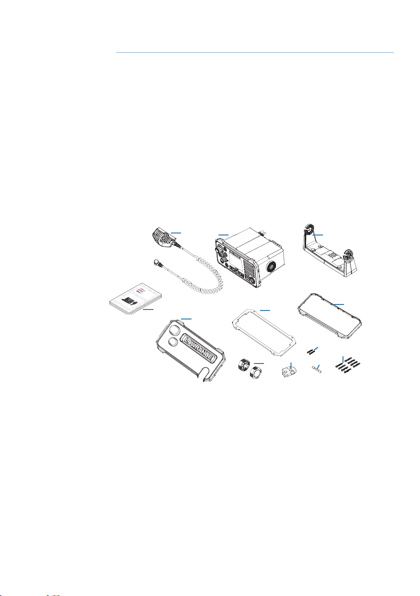
Checklist
The following items should be supplied in the box. Check before
starting the installation and contact your dealer if an item is missing.
¼ Note: A VHF antenna is not provided. Consult your Lowrance dealer
for advice on selecting the correct antenna for your installation:
2
VHF RADIO
User Guide
Installation Manual
ENGLISH
ENGLISH
Installation Manual
ENGLISH
Installation Manual
ENGLISH
bandg.com
bandg.com
bandg.com
12
1
4
3
7
5
10
9
6
11
8
1. VHF radio
2. Removable hand mic
3. Bracket for gimbal mounting
4. Gasket for recessed mounting
5. Sun cover
6. Knobs for bracket
7. Bezel trim
8. 8 A (3 AG) spare fuse
9. Bulkhead mount for hand mic
10. 2 pcs 3.5 x 20 mm, stainless steel, panhead Phillips
11. 8 pcs 4 x 25 mm, stainless steel, panhead Phillips.
12. Documents: user’s manual, warranty card, mounting template.
Installation | Link-9 User Guide
| 43
Page 45

Installation options
There are two mounting options for the radio.
• Bracket mount:
Using the supplied gimballing bracket the radio can be mounted to
either sit on top of, or hang underneath any flat horizontal surface.
The radio can be removed for storage and the viewing angle can be
adjusted.
• Flush mount:
The radio is recessed into a cavity, showing only the face of the
radio. The radio fixture is permanent and the viewing angle cannot
be adjusted.
Selecting a suitable mounting location
Whichever installation method you choose, please check the following
before doing any cutting or drilling. The chosen location must:
• Be at least 1 m (3’) from the VHF antenna.
• Allow easy access to the rear of the radio for connection to the 12 V
DC electrical source, the antenna and any network wiring.
• Be at least 45 cms (1.5’) from a compass to avoid creating magnetic
deviation of the compass.
• Have a suitable space close by for installing the microphone
bulkhead mount.
• Provide easy access to the controls on the front panel.
• If intending to use the built-in GPS antenna, it must be in a
location that provides optimal GPS performance, see “Built-in GPS
considerations” on page 45.
44 |
Viewing angle
The VHF radio has a large LCD screen with the optimum horizontal
and vertical viewing angles within approx. +/-20 deg. Ensure the
chosen location provides a suitable view of the display. Ideally, the
user should be directly in front of the display or no more than +/-20
deg from the front of the display.
¼ Note: If unsure, temporarily power up the radio and ensure the loca-
tion is suitable.
20°
20°
Installation | Link-9 User Guide
20°
20°
Page 46

Built-in GPS considerations
1. The built-in GPS antenna is mounted in the front face of this radio
above the speaker grill.
2. If you intend to use the built-in GPS Antenna in this radio, you
must ensure a suitable mounting location that allows optimal GPS
performance.
3. There must not be any metallic or large obstacles in the path
between the radio and the sky. The more obstacles in the way, the
weaker the GPS signal getting to the antenna.
4. If the radio is mounted in an alloy or ferrous boat, or below decks,
then an external GPS antenna is recommended. Seek professional
guidance if unsure.
Bracket installation
The gimbal bracket provides an adjustable viewing angle with a 20º
tilt range, so ensure the selected mounting location will provide the
desired viewing and operating conditions:
1. Hold the bracket at the chosen location and use a soft pencil to
mark the screw hole positions onto the mounting surface.
2. Use a 3 mm (1/8” ) drill bit to drill the 4 pilot holes.
3. Using a Phillips screwdriver, secure the bracket using the supplied
4x25 mm selftapping screws to the mounting location.
4. Fit the radio into the bracket.
5. Insert the two mounting knobs through the holes and tighten them
sufficiently to hold the radio at the desired viewing angle.
6. Fit the bezel trim to the front of the radio to cover dash mount screw
holes.
Installation | Link-9 User Guide
| 45
Page 47

Flush installation
1. Tape the installation template onto the chosen mounting location.
2. Cut out the area marked by the solid dark line (the dashed line
indicates the total area that will be covered by the radio fascia after
installation).
3. Use a 2.5 mm (3/32” ) drill bit to drill the 4 pilot holes.
4. Remove the installation template.
5. Fit the gasket to the radio.
6. Slide the radio into the cavity.
7. Using a Phillips screwdriver, secure the radio using the supplied
3.5x20 mm selftapping screws to the mounting location.
8. Fit the bezel trim to cover the 4 mounting screws.
46 |
Install the hand mic bulkhead bracket
1. Hold the hand mic bulkhead bracket at the chosen location and
mark the screw hole positions on the mounting surface.
¼ Note: Ensure that the microphone curly cable will comfortably reach
this location BEFORE you drill.
2. Use a 2.5 mm (3/32” ) drill bit to drill the 2 pilot holes.
3. Using a Phillips screwdriver, secure the Mic mount using the
supplied 3.5x20 mm selftapping screws to the mounting location.
4. Hang the fist mic on the mount.
Installation | Link-9 User Guide
Page 48

Install the external GPS-500 Antenna (optional)
It is not recommended that the GPS antenna is mounted up a mast
where the motion of the vessel will cause the antenna to swing and
potentially reduce the accuracy of the GPS position.
Do not mount the GPS antenna within 1 m of a transmitting device.
Mount the GPS-500 to either a pole or hard surface then run the
cable to the transceiver. In all cases, ensure the selected location
enables the antenna to have a clear, unobstructed view of the sky.
To pole mount the external GPS-500 antenna, you will require a
1-inch 14 TPI thread pole:
• Screw the pole adapter onto the threaded portion of the pole.
• Feed the cable attached to the GPS antenna through the adapter
and pole.
• Mount the pole into position.
• Fit the GPS antenna to the pole adapter using the 2 small screws.
To surface mount the external GPS-500 antenna, select a flat clean
surface area that has a clear view of the sky. Mount the antenna
using the supplied gasket and the 2 small screws:
• Mark and drill the 2 mounting holes and a further hole if necessary
for the GPS cable.
• Install the gasket by firstly threading the attached cable through the
centre of the gasket.
• Screw the GPS antenna to the mounting surface.
¼ Note: Ensure the surface mounting area is clean with no dirt, old
paint or debris.
Installation | Link-9 User Guide
| 47
Page 49

• Run the GPS cable to the transceiver:
!
• Route the cable to your VHF transceiver unit, adding any necessary
extension cables.
• Connect the cable from the GPS antenna to the GPS connector
(SMA) on the VHF transceiver as shown below.
Connect the radio wiring
All wiring on the radio should be done with the vessel power supply
turned off. While radio power is polarity protected, the fuse will blow
if the connection is made the wrong way round. Ensure any unused
bare wires are isolated from each other, to prevent the potential of
a short circuit. If using the NMEA 2000 connection, ensure network
topology rules are followed closely.
Warning: never operate the radio without the antenna
connected. This may damage the transmitter.
The connectors are on the rear of the base unit, as follows:
48 |
VHF
antenna
Chart plotter
GPS
antenna
T
Battery (+)
12 V DC (nom)
Battery (-)
T
NMEA
0183
GPS
antenna
1
_
2
+
34 75
External
Hailer
speaker
6
speaker
8
1. Battery - (BLACK): connect to vessel’s negative busbar.
2. Battery + (RED): connect to vessel’s 12 V DC, via a switch panel or
Installation | Link-9 User Guide
Page 50

breaker (comes with inline 8 amp fuse ready fitted).
3. Auxiliary port connections as follows:
Wire color Item Connect to
GR AY External speaker + Positive terminal of the optional
external speaker.
GR AY/BLAC K External speaker - Negative terminal of the optional
external speaker.
YELLOW NMEA 0183 RX_A TX_A of chart plotter, or active GPS
antenna.
GREEN NMEA 0183 RX_B TX_B of chart plotter, or active GPS
antenna.
WHITE NMEA 0183 TX_A RX_A of chart plotter.
BROWN NMEA 0183 TX_B RX_B of chart plotter.
BLUE Hailer speaker + Positive terminal of the optional
Hailer speaker.
BLUE/BLACK Hailer speaker - Negative terminal of the optional
Hailer speaker.
4. Antenna: connect to a marine VHF antenna using 50 ohm cable
fitted with a PL-259 connector.
5. GND: optional ground connection. May help with induced noise
issues.
6. GPS antenna (SMA): connect to external passive GPS antenna.
7. NMEA 2000 network connection. Can be connected to a NMEA
2000 compatible MFD with built-in GPS or external GPS antenna.
8. Handset microphone (rear) connection: Alternative connection
for the removable handset microphone. Optional 1 m and 5 m
extension cable available.
¼ Note: External speaker, Hailer, passive GPS antenna and plotter con-
nections are optional.
Installation | Link-9 User Guide
| 49
Page 51

First startup conguration
The first time the radio is powered up, the user is prompted to make
a series of setting selections in order to allow the radio to perform
to its full potential. Some steps must be completed; some are
optional and can be completed later. The steps are outlined below
for reference:
1. Select the country and region the radio will be operated in:
2. Enter MMSI number if known, or skip to next step. Re-enter number
to confirm correct entry:
¼ Note: MMSI entry can only be done once. Changing the MMSI
requires radio be returned to a Lowrance dealer.
50 |
3. If you have selected the Country mode to be EU, some EU regions
require you to setup ATIS. Enter the ATIS ID number. Re-enter
number to confirm correct entry:
4. Enter vessel call sign if known, or skip to next step:
Installation | Link-9 User Guide
Page 52

5. Select a GPS source:
6. Set the time offset for your region. Choose whether to display time
in 12 or 24 hour:
MMSI and ATIS ID
The MMSI is a unique 9 digit number and the ATIS ID is a 10 digit
number. They are used on marine transceivers that have DSC (Digital
Select Calling) functionality.
• An MMSI remains with a vessel, even if the vessel is sold on.
• An MMSI has 9 numeric digits (xxxxxxxxx). Your MMSI must not
commence with a ‘0’.
• A Group MMSI begins with ‘0’ followed by 8 numeric digits
(0xxxxxxxx).
• A Coast Station MMSI begins with 00 followed by 7 numeric digits
(00xxxxxxx).
• By law, you are not able to change your MMSI once it is entered into
the radio. This is why there is the confirmation screen when entering
the MMSI.
• An ATIS ID is only required in certain EU countries when navigating
some inland waterways. It is usually a different number to your
MMSI.
• If you need to have the MMSI in the radio changed, the radio must
be taken back to your Lowrance dealer.
Installation | Link-9 User Guide
| 51
Page 53

ATIS
Automatic Transmitter Identification System (ATIS) is required for
vessels making VHF transmissions whilst on the inland waterways of
the Regional Arrangement Concerning the Radiotelephone Service
on Inland Waterways (RAINWAT) signatory countries.
RAINWAT is an agreement to implement common principles and
rules for the safe carriage of people and goods on Inland Waterways.
The signatory countries are: Austria, Belgium, Bulgaria, Croatia, the
Czech Republic, France, Germany, Hungary, Luxembourg, Moldova,
Montenegro, the Netherlands, Poland, Romania, Serbia, the Slovak
Republic and Switzerland.
Where a VHF is required on the inland waterways of the signatory
countries, this must be capable of ATIS transmissions, and have the
feature activated. An ATIS number is required which is issued by
Ofcom when you add one or more pieces of ATIS equipment to
your Ship Radio Licence.
If you don’t have a user MMSI or ATIS ID, contact the appropriate
licensing authority in your country. If you’re unsure who to contact,
consult your Lowrance dealer.
52 |
Installation | Link-9 User Guide
Page 54

9
Specications
GENERAL
Power supply: 12 V DC battery system
Nominal operating voltage: + 13.6 V DC
Low battery alert: 10.5 V DC +/- 0.5 V
Over voltage protection: > 15.8 V +/- 0.5 V
Current drain (Transmit): ≤ 6 A @ 25 W / 1.5 A @ 1W (12 V DC)
Current drain (Receive): Less than 450 mA in standby
Replacement Fuse: 8 A, Glass type 3 AG; 32 mm (1.25”)
Temperature range: -20 ºC to +55 ºC (-4 ºF to 131 ºF)
Usable channels: International, USA, Canada, Weather
(country specific)
Mode: 16K0G3E (FM) / 16K0G2B (DSC)
DSC mode: Class D (Global) with dual receiver
(individual CH70)
Standards - EU: EN60950-1, IEC 60529, EN 60945/
IEC 60945, EN 303 843-1 V2.1.1, EN
303 843-2 V2.1.1, EN 301 025 V2.2.1,
EN 303 413 V1.1.1, EN 300 698 V2.2.1
Standards - US/CAN: US/CAN: FCC Part 80, RSS-Gen Issue
5, RSS-182 Issue 5
Standards - INT: AS/NZS ETSI EN 301 025
Standards - AIS: ITU-R M.1371-5
Frequency range,
- Transmitter:
- Receiver:
Channel spacing: 25 KHz
Frequency stability: ± 5 ppm
Frequency control: PLL
156.025 - 157.425 MHz
156.050 - 163.275 MHz
PHYSICAL
LCD display: FSTN 256x160 pixels, monochrome
Contrast control: Yes
Backlight synching: Yes, via NMEA 2000 network
Specications | Link-9 User Guide
| 53
Page 55

Backlight: White LED; adjustable in 10 levels;
Day and Night mode
VHF antenna connector: SO-239 (50 ohm)
GPS antenna connector: SMA (female)
Waterproof: IPx7
Dimensions: W=208.3 mm (8.2”) x H=107.2 mm
(4.22”) x D=163.4 mm (6.43”) without bracket
Weight: 1.46 kg (3.2 lbs)
Compass safe distance: 0.5 m (1.5’)
NMEA 0183 port: Yes
NMEA 0183 input: RMC, GGA, GLL, GNS
NMEA 0183 output: Yes, DSC ( for DSC call), DSE (for
enhanced position), MOB
NMEA 2000 port: Yes
External speaker: Yes - 4 ohms, minimum 4 W
Hailer speaker: Yes - 4 ohms, minimum 30 W
Handset mic: Removable.
Front or rear mount connector
54 |
FEATURES
Flush mount kit Yes
Local/Distant control: Yes
Position polling: Yes
Group call: Yes
Call logs: Yes - 20 individual and 10 distress
Channel naming: Yes
Tri watch: Yes
Favourite channel scan: Yes
All scan: Yes
User programmable MMSI: Yes
MMSI and NAME directory: Yes - 20 numbers & group
Software updates: Yes, via NMEA 2000
Specications | Link-9 User Guide
Page 56

TRANSMITTER
Frequency error: ≤± 1.5 KHz
Output power: 25 W (23 ± 2) / 1 W (0.8 ± 0.2)
Transmitter protection: Open / short circuit of antenna
Max Frequency deviation: ≤± 5
Spurious & harmonics Hi/Lo:
Modulation Distortion
±3KHz:
S/N at 3KHz Deviation: ≥ 40 dB
Audio Response at 1KHz: +1 to -3dB of 6 dB/octave from
DSC TX deviation,
- at 1.3K:
- at 2.1K:
ATIS TX deviation,
- at 1.3 KHz:
- at 2.1 KHz:
RECEIVER
12dB SINAD sensitivity: 0.25 µV (distant) / 0.8 µV (local)
20db SINAD sensitivity: 0.35 µV
Adjacent CH selectivity: more than 70 db
Spurious response: more than 70 db
Intermodulation rejection: more than 68 db
Residual noise level: more than -40 db unsquelched
Audio output power: 2 W (with 8 ohm at 10% distortion)
≤ 0.25 µ W
≤ 10 %
300 hz to 3 KHz
2.6 ± 0.26 KHz
4.2 ± 0.42 KHz
1.3 ± 0.13 KHz
2.1 ± 0.21 KHz
4 W (with 4 ohm external speaker
BUILT-IN GPS RECEIVER
Receiving frequency: 1575.42 MHz
Tracking code: C/A code
Number of channels: 72 channels
Horizontal accuracy: <10 m
Position fixing time: Warm start: 30s, Cold start: 90s
Position update interval: 1 second typical
Specications | Link-9 User Guide
| 55
Page 57

HAILER
Audio power out: 30 W @ 4 Ohms
AIS
AIS function: Yes, dual receivers (receive only)
Receiver frequency: 161.975 MHz (CH87) &
162.025 MHz (CH88)
Supported AIS information: Status; Destination; ETA; Vessel
Name; Type of vessel; Call sign;
MMSI number; IMO number;
Draft/Size of vessel; Vessel position;
SOG/COG/Rate of turn/Heading
AIS targets: Maximum 150
¼ Note: Specifications are subject to change without notice.
56 |
Specications | Link-9 User Guide
Page 58

10
Channel charts
The following channel charts are provided for reference only and
may not be correct for all regions. It is the operators responsibility
to ensure correct channels and frequencies are used for local
regulations.
EU and INTERNATIONAL channel chart
The following is a table of transmiting frequencies in the VHF
maritime mobile band.
¼ Note: For assistance in understanding the Table, see Notes a) to zz)
below. (WRC-15)
¼ Note: The Table below defines the channel numbering for maritime
VHF communications based on 25 kHz channel spacing and use of
several duplex channels. The channel numbering and the conversion of two-frequency channels for single-frequency operation shall
be in accordance with Recommendation ITU-R M.1084-5 Annex
4, Tables 1 and 3. The Table below also describes the harmonized
channels where the digital technologies defined in the most recent
version of Recommendation ITU-R M.1842 could be deployed.
( W RC-15 )
Channel charts | Link-9 User Guide
| 57
Page 59

Transmitting frequencies
(MHz)
Channel
designator
01 156.050 160.650 D TELEPHONE m)
02 156.100 160.700 D TELEPHONE m)
03 156.150 160.750 D TELEPHONE m)
04 156.200 160.800 D PORT OPS m)
05 156.250 160.850 D PORT OPS/
06 156.300 156.300 S SAFETY f)
07 156.350 160.950 D PORT OPS m)
08 156.400 156.400 S COMMERCIAL
09 156.450 156.450 S CALLING i)
10 156.500 156.500 S COMMERCIAL h), q)
11 156.550 156.550 S VTS q)
12 156.600 156.600 S PORT OPS/
13 156.650 156.650 S BRIDGE COM k)
14 156.700 156.700 S PORT OPS/
15 156.750 156.750 S PORT OPS 1W g)
16 156.800 156.800 S DISTRESS f)
17 156.850 156.850 S SAR 1W g)
18 156.900 161.500 D PORT OPS m)
19 156.950 161.550 D SHIP-SHORE t), u), v)
20 157.000 161.600 D PORT OPS t), u), v)
21 157.050 161.650 D PORT OPS w), y)
22 157.100 161.700 D PORT OPS w), y)
23 157.150 161.750 D TELEPHONE w), x), y)
24 157.200 161.800 D TELEPHONE w), ww),
25 157.250 161.850 D TELEPHONE w), ww),
26 157.300 161.900 D TELEPHONE w), ww),
27 157.350 161.950 D TELEPHONE z)
28 157.400 162.000 D TELEPHONE z)
60 156.025 160.625 D TELEPHONE m)
61 156.075 160.675 D PORT OPS m)
62 156.125 160.725 D PORT OPS m)
63 156.175 160.775 D PORT OPS m)
64 156.225 160.825 D TELEPHONE m)
65 156.275 160.875 D PORT OPS m)
66 156.325 160.925 D PORT OPS m)
67 156.375 156.375 S BRIDGE COM h)
From ship
stations
From coast
stations
S/D/R
Channel
name
VTS
VTS
VTS
Restriction Notes
m)
x), y)
x), y)
x), y)
58 |
Channel charts | Link-9 User Guide
Page 60

68 156.425 156.425 S SHIP-SHIP
69 156.475 156.475 S PORT OPS
71 156.575 156.575 S PORT OPS
72 156.625 156.625 S SHIP-SHIP i)
73 156.675 156.675 S PORT OPS h), i)
74 156.725 156.725 S PORT OPS
75 156.775 156.775 S PORT OPS 1W n), s)
76 156.825 156.825 S SHIP-SHIP 1W n), s)
77 156.875 156.875 S SHIP-SHIP
78 156.925 161.525 D SHIP-SHORE t), u), v)
79 156.975 161.575 D PORT OPS t), u), v)
80 157.025 161.625 D PORT OPS w), y)
81 157.075 161.675 D TELEPHONE w), y)
82 157.125 161.725 D TELEPHONE w), x), y)
83 157.175 161.775 D TELEPHONE w), x), y)
84 157.225 161.825 D TELEPHONE w), ww),
85 157.275 161.875 D TELEPHONE w), ww),
86 157.325 161.925 D TELEPHONE w), ww),
87 157.375 157.375 S TELEPHONE z)
88 157.425 157.425 S TELEPHONE z)
1019 156.950 156.950 S TELEPHONE
1020 157.000 157.000 S TELEPHONE
1078 156.925 156.925 S TELEPHONE
1079 156.975 156.975 S TELEPHONE
2006 160.900 160.900 S TELEPHONE r)
2019 161.550 161.550 S TELEPHONE
2020 161.600 161.600 S TELEPHONE
2078 161.525 161.525 S TELEPHONE
2079 161.575 161.575 S TELEPHONE
x), y)
x), y)
x), y)
Editorial note: The note numbering below is provisional and will be
aligned during final preparations of the new edition of the Radio
Regulations.
Notes referring to the Table
General notes:
a) Administrations may designate frequencies in the inter-ship, port
operations and ship movement services for use by light aircraft
and helicopters to communicate with ships or participating coast
stations in predominantly maritime support operations under the
conditions specified in Nos. 51.69, 51.73, 51.74, 51.75, 51.76, 51.77
Channel charts | Link-9 User Guide
| 59
Page 61

and 51.78. However, the use of the channels which are shared with
public correspondence shall be subject to prior agreement between
interested and affected administrations.
b) The channels of the present Appendix, with the exception of
channels 06, 13, 15, 16, 17, 70, 75 and 76, may also be used for
high-speed data and facsimile transmissions,subject to special
arrangement between interested and affected administrations.
c) The channels of the present Appendix, with the exception of
channels 06, 13, 15, 16, 17, 70, 75 and 76, may be used for directprinting telegraphy and data transmission, subject to special
arrangement between interested and affected administrations.
( W RC-12 )
d) The frequencies in this table may also be used for radio
communications on inland waterways in accordance with the
conditions specified in No.5.226.
e) Administrations may apply 12.5 kHz channel interleaving on a non-
interference basis to 25 kHz channels, in accordance with the most
recent version of Recommendation ITU-R M.1084,provided:
• it shall not affect the 25 kHz channels of the present Appendix
maritime mobile distress and safety, automatic identification
system (AIS), and data exchange frequencies, especially the
channels 06, 13, 15, 16, 17, 70, AIS 1 and AIS 2, nor the technical
characteristics set forth in Recommendation ITU-R M.489-2 for
those channels;
• implementation of 12.5 kHz channel interleaving and
consequential national requirements shall be subject to
coordination with affected administrations. (WRC-12)
60 |
Specic notes
f) The frequencies 156.300 MHz (channel 06), 156.525 MHz (channel
70), 156.800 MHz (channel 16), 161.975 MHz (AIS 1) and 162.025 MHz
(AIS 2) may also be used by aircraft stations for the purpose of search
and rescue operations and other safety-related communication.
( W RC- 07 )
g) Channels 15 and 17 may also be used for on-board communications
provided the effective radiated power does not exceed 1W, and
subject to the national regulations of the administration concerned
when these channels are used in its territorial waters.
h) Within the European Maritime Area and in Canada, these
frequencies (channels 10, 67, 73) may also be used, if so required,
by the individual administrations concerned, for communication
between ship stations, aircraft stations and participating land
Channel charts | Link-9 User Guide
Page 62

stations engaged in coordinated search and rescue and antipollution operations in local areas, under the conditions specified in
Nos. 51.69, 51.73, 51.74, 51.75, 51.76, 51.77 and 51.78.
i) The preferred first three frequencies for the purpose indicated in
Note a) are 156.450 MHz (channel 09), 156.625 MHz (channel 72) and
156.675 MHz (channel73).
j) Channel 70 is to be used exclusively for digital selective calling for
distress, safety and calling.
k) Channel 13 is designated for use on a worldwide basis as a
navigation safety communication channel, primarily for intership
navigation safety communications. It may also be used for the ship
movement and port operations service subject to the national
regulations of the administrations concerned.
l) These channels (AIS 1 and AIS 2) are used for an automatic
identification system (AIS) capable of providing world wide
operation, unless other frequencies are designated on a regional
basis for this purpose. Such use should be in accordance with the
most recent version of Recommendation ITU-RM.1371. (WRC-07)
m) These channels may be operated as single frequency channels,
subject to coordination with affected administrations. The following
conditions apply for single frequency usage:
• The lower frequency portion of these channels may be operated
as single frequency channels by ship and coast stations.
• Transmission using the upper frequency portion of these channels
is limited to coast stations.
• If permitted by administrations and specified by national
regulations, the upper frequency portion of these channels may
be used by ship stations for transmission. All precautions should
be taken to avoid harmful interference to channels AIS 1, AIS 2,
2027* and 2028*. (WRC-15)
* From 1 January 2019, channel 2027 will be designated ASM 1
and channel 2028 will be designated ASM 2.
n) With the exception of AIS, the use of these channels (75 and 76)
should be restricted to navigation-related communications only
and all precautions should be taken to avoid harmful interference to
channel 16, by limiting the output power to1W. (WRC-12)
o) (SUP - WRC-12)
p) Additionally, AIS 1 and AIS 2 may be used by the mobile-satellite
service (Earth-to-space) for the reception of AIS transmissions from
ships. (WRC-07)
q) When using these channels (10 and 11), all precautions should be
Channel charts | Link-9 User Guide
| 61
Page 63

taken to avoid harmful interference to channel70. (WRC-07)
r) In the maritime mobile service, this frequency is reserved for
experimental use for future applications or systems (e.g. new
AIS applications, man over board systems,etc.).If authorized by
administrations for experimental use, the operation shall not cause
harmful interference to, or claim protection from, stations operating
in the fixed and mobile services. (WRC-12)
s) Channels 75 and 76 are also allocated to the mobile-satellite service
(Earth-to-space) for the reception of long-range AIS broadcast
messages from ships (Message 27; see the most recent version of
Recommendation ITU-RM.1371). (WRC-12)
w. In Regions 1 and 3:
Until 1 January 2017, the frequency bands 157.200-157.325 MHz
and 161.800-161.925 MHz (corresponding to channels: 24, 84, 25, 85,
26 and 86) may be used for digitally modulated emissions, subject
to coordination with affected administrations. Stations using these
channels or frequency bands for digitally modulated emissions shall
not cause harmful interference to, or claim protection from, other
stations operating in accordance with Article 5.
From 1 January 2017, the frequency bands 157.200-157.325 MHz
and 161.800-161.925 MHz (corresponding to channels: 24, 84, 25,
85, 26 and 86) are identified for the utilization of the VHF Data
Exchange System (VDES) described in the most recent version of
Recommendation ITU-R M.2092. These frequency bands may also be
used for analogue modulation described in the most recent version
of Recommendation ITU-R M.1084 by an administration that wishes
to do so, subject to not causing harmful interference to, or claiming
protection from other stations in the maritime mobile service using
digitally modulated emissions and subject to coordination with
affectedadministrations. (WRC-15)
ww. In Region 2, the frequency bands 157.200-157.325 and 161.800-
161.925 MHz (corresponding to channels: 24, 84, 25, 85, 26
and 86) are designated for digitally modulated emissions in
accordance with the most recent version of Recommendation
ITU-R M.1842.
In Canada and Barbados, from 1 January 2019 the frequency
bands 157.200-157.275 and 161.800-161.875 MHz (corresponding
to channels: 24, 84, 25 and 85) may be used for digitally
modulated emissions, such as those described in the most
recent version of Recommendation ITU-R M.2092, subject to
coordination with affected administrations. (WRC-15)
x) From 1 January 2017, in Angola, Botswana, Lesotho, Madagascar,
62 |
Channel charts | Link-9 User Guide
Page 64

Malawi, Mauritius, Mozambique, Namibia, Democratic Republic of
the Congo, Seychelles, South Africa, Swaziland, Tanzania, Zambia
and Zimbabwe, the frequency bands 157.125-157.325 and 161.725-
161.925 MHz (corresponding to channels: 82, 23, 83, 24, 84, 25, 85, 26
and 86) are designated for digitally modulated emissions.
From 1 January 2017, in China, the frequency bands 157.150 -
157.325 and 161.750 - 161.925 MHz (corresponding to channels: 23,
83, 24, 84, 25, 85, 26 and 86) are designated for digitally modulated
emissions. (WRC-12)
y) These channels may be operated as single or duplex frequency
channels, subject to coordination with affected administrations.
( W RC-12 )
z) Until 1 January 2019, these channels maybe used for possible testing
of future AIS applications without causing harmful interference
to, or claiming protection from, existing applications and stations
operating in the fixed and mobile services.
From 1 January 2019, these channels are each split into two simplex
channels. The channels 2027 and 2028 designated as ASM 1 and
ASM 2 are used for application specific messages (ASM) as described
in the most recent version of Recommendation ITU-R M.2092.
(WRC-15)
AAA) From 1 January 2019, the channels 24, 84, 25 and 85 may be merged
in order to form a unique duplex channel with a bandwidth of 100
kHz in order to operate the VDES terrestrial component described in
the most recent version of Recommendation ITU-RM.2092. (WRC-
15)
mm) Transmission on these channels is limited to coast stations. If
permitted by administrations and specified by national regulations,
these channels may be used by ship stations for transmission.
All precautions should be taken to avoid harmful interference to
channels AIS 1, AIS 2, 2027* and 2028*. (WRC-15)
* From 1 January 2019, channel 2027 will be designated ASM 1 and
channel 2028 will be designated ASM 2.
w1) In Regions 1 and 3:
Until 1 January 2017, the frequency bands 157.025-157.175 MHz and
161.625-161.775 MHz (corresponding to channels: 80, 21, 81, 22, 82,
23 and 83) may be used for digitally modulated emissions, subject
to coordination with affected administrations. Stations using these
channels or frequency bands for digitally modulated emissions shall
not cause harmful interference to, or claim pro-tection from, other
stations operating in accordance with Article 5.
Channel charts | Link-9 User Guide
| 63
Page 65

From 1 January 2017, the frequency bands 157.025-157.100 MHz
and 161.625-161.700 MHz (corresponding to channels: 80, 21, 81
and 22) are identified for utilization of the digital systems described
in the most recent version of Recommendation ITU-R M.1842 using
multiple 25 kHz contiguous channels.
From 1 January 2017, the frequency bands 157.150-157.175 MHz
and 161.750-161.775 MHz (corresponding to channels: 23 and 83)
are identified for utilization of the digital systems described in the
most recent version of Recommendation ITU-R M.1842 using two
25 kHz contiguous channels. From 1 January 2017, the frequencies
157.125 MHz and 161.725 MHz (corresponding to channel: 82) are
identified for the utilization of the digital systems described in the
most recent version of Recommendation ITU-R M.1842.
The frequency bands 157.025-157.175 MHz and 161.625-161.775
MHz (corresponding to channels: 80, 21, 81, 22, 82, 23 and 83) can
also be used for analogue modulation described in the most recent
version of Recommendation ITU-R M.1084 by an administration
that wishes to do so, subject to not claiming protection from
other stations in the maritime mobile service using digitally
modulated emissions and subject to coordination with affected
administrations. (WRC-15)
zx) In the United States, these channels are used for communication
between ship stations and coast stations for the purpose of public
correspondence. (WRC-15)
zz) From 1 January 2019, channels 1027, 1028, 87 and 88 are used as
single-frequency analogue channels for port operation and ship
movement. (WRC-15)
Source: ITU Radio Regulations (2016); reproduced with permission from ITU
64 |
Channel charts | Link-9 User Guide
Page 66

USA channel chart
Transmitting frequencies (MHz)
Channel
designator
6 156.300 156.300 S SAFETY
8 156.400 156.400 S COMMERCIAL
9 156.450 156.450 S CALLING
10 156.500 156.500 S COMMERCIAL
11 156.550 156.550 S VTS
12 156.600 156.600 S PORT OPS/VTS
13 156.650 156.650 S BRIDGE COM 1W
14 156.700 156.700 S PORT OPS/VTS
15 -- 156.750 R ENVIROMENTAL RX ONLY
16 156.800 156.800 S DISTRESS
17 156.850 156.850 S SAR 1W
20 157.000 161.600 D PORT OPS
24 157.200 161.800 D TELEPHONE
25 157.250 161.850 D TELEPHONE
26 157.300 161.900 D TELEPHONE
27 157.350 161.950 D TELEPHONE
28 157.400 162.000 D TELEPHONE
67 156.375 156.375 S BRIDGE COM 1W
68 156.425 156.425 S SHIP-SHIP
69 156.475 156.475 S SHIP-SHIP
71 156.575 156.575 S SHIP-SHIP
72 156.625 156.625 S SHIP-SHIP
73 156.675 156.675 S PORT OPS
74 156.725 156.725 S PORT OPS
75 156.775 156.775 S PORT OPS 1W
76 156.825 156.825 S PORT OPS 1W
77 156.875 156.875 S PORT OPS 1W
84 157.225 161.825 D TELEPHONE
85 157.275 161.875 D TELEPHONE
86 157.325 161.925 D TELEPHONE
87 157.375 157.375 S TELEPHONE
88 157.425 157.425 S INTER-SHIP
1001 156.050 156.050 S PORT OPS/VTS
1005 156.250 156.250 S PORT OPS/VTS
From ship
stations
From coast
stations
S/D/R Channel name Restrictions
Channel charts | Link-9 User Guide
| 65
Page 67

1007 156.350 156.350 S COMMERCIAL
1018 156.900 156.900 S COMMERCIAL
1019 156.950 156.950 S COMMERCIAL
1020 157.000 157.000 S PORT OPS
1021 157.050 157.050 S US COAST GRD
1022 157.100 157.100 S US COAST GRD
1023 157.150 157.150 S US COAST GRD
1063 156.175 156.175 S PORT OPS/VTS
1065 156.275 156.275 S PORT OPS
1066 156.325 156.325 S PORT OPS
1078 156.925 156.925 S SHIP-SHIP
1079 156.975 156.975 S COMMERCIAL
1080 157.025 157.025 S COMMERCIAL
1081 157.075 157.075 S RESTRICTED
1082 157.125 157.125 S RESTRICTED
1083 157.175 157.175 S RESTRICTED
USA weather channels
Transmitting frequencies (MHz)
Channel
designator
WX1 -- 162.550 R NOAA WX1 RX ONLY
WX2 -- 162.400 R NOAA WX2 RX ONLY
WX3 -- 162.475 R NOAA WX3 RX ONLY
WX4 -- 162.425 R NOAA WX4 RX ONLY
WX5 -- 162.450 R NOAA WX5 RX ONLY
WX6 -- 162.500 R NOAA WX6 RX ONLY
WX7 -- 162.525 R NOAA WX7 RX ONLY
From ship
stations
From coast
stations
S/D/R Channel name Restrictions
66 |
Channel charts | Link-9 User Guide
Page 68

CANADA channel chart
Frequencies
Channel
designator
1 156.050 160.650 D TELEPHONE
2 156.100 160.700 D TELEPHONE
3 156.150 160.750 D TELEPHONE
4 156.200 160.800 D CANADIAN CG
5 156.250 160.850 D TELEPHONE
6 156.300 156.300 S SAFETY
7 156.350 160.950 D TELEPHONE
8 156.400 156.400 S COMMERCIAL
9 156.450 156.450 S VTS
10 156.500 156.500 S VTS
11 156.550 156.550 S VTS
12 156.600 156.600 S PORT OPS/VTS
13 156.650 156.650 S BRIDGE COM 1W
14 156.700 156.700 S PORT OPS/VTS
15 156.750 156.750 S COMMERCIAL 1W
16 156.800 156.800 S DISTRESS
17 156.850 156.850 S SAR 1W
18 156.900 161.500 D TELEPHONE
19 156.950 161.550 D CANADIAN CG
20 157.000 161.600 D CANADIAN CG 1W
21 157.050 161.650 D CANADIAN CG
22 157.100 161.700 D TELEPHONE
23 157.150 161.750 D TELEPHONE
24 157.200 161.800 D TELEPHONE
25 157.250 161.850 D TELEPHONE
26 157.300 161.900 D TELEPHONE
27 157.350 161.950 D TELEPHONE
28 157.400 162.000 D TELEPHONE
60 156.025 160.625 D TELEPHONE
61 156.075 160.675 D CANADIAN CG
62 156.125 160.725 D CANADIAN CG
63 156.175 160.775 D TELEPHONE
64 156.225 160.825 D TELEPHONE
65 156.275 160.875 D TELEPHONE
MHz (ship) MHz (coast) S/D/R Channel Name: RESTRICTIONS
Channel charts | Link-9 User Guide
| 67
Page 69

66 156.325 160.925 D TELEPHONE
67 156.375 156.375 S COMMERCIAL
68 156.425 156.425 S SHIP-SHIP
69 156.475 156.475 S COMMERCIAL
71 156.575 156.575 S VTS
72 156.625 156.625 S SHIP-SHIP
73 156.675 156.675 S COMMERCIAL
74 156.725 156.725 S VTS
75 156.775 156.775 S PORT OPS 1W
76 156.825 156.825 S PORT OPS 1W
77 156.875 156.875 S PORT OPS 1W
78 156.925 161.525 D TELEPHONE
79 156.975 161.575 D TELEPHONE
80 157.025 161.625 D TELEPHONE
81 157.075 161.675 D TELEPHONE
82 157.125 161.725 D CANADIAN CG
83 157.175 161.775 D CANADIAN CG
84 157.225 161.825 D TELEPHONE
85 157.275 161.875 D TELEPHONE
86 157.325 161.925 D TELEPHONE
87 157.375 157.375 S PORT OPS
88 157.425 157.425 S PORT OPS
1001 156.050 156.050 S COMMERCIAL
1005 156.250 156.250 S PORT OPS/VTS
1007 156.350 156.350 S COMMERCIAL
1018 156.900 156.900 S COMMERCIAL
1019 156.950 156.950 S CANADIAN CG
1020 157.000 157.000 S PORT OPS
1021 157.050 157.050 S RESTRICTED
1022 157.100 157.100 S CANADIAN CG
1024 157.200 157.200 S PORT OPS
1025 157.250 157.250 S PORT OPS
1026 157.300 157.300 S PORT OPS
1027 157.350 157.350 S CANADIAN CG
1061 156.075 156.075 S CANADIAN CG
1062 156.125 156.125 S CANADIAN CG
1063 156.175 156.175 S TELEPHONE
68 |
Channel charts | Link-9 User Guide
Page 70

1064 156.225 156.225 S RESTRICTED
1065 156.275 156.275 S PORT OPS
1066 156.325 156.325 S PORT OPS
1078 156.925 156.925 S SHIP-SHIP
1079 156.975 156.975 S COMMERCIAL
1080 157.025 157.025 S COMMERCIAL
1083 157.175 157.175 S RESTRICTED
1084 157.225 157.225 S PORT OPS
1085 157.275 157.275 S CANADIAN CG
1086 157.325 157.325 S PORT OPS
2019 -- 161.550 R PORT OPS RX ONLY
2020 -- 161.600 R PORT OPS RX ONLY
2023 -- 161.750 R SAFETY RX ONLY
2026 -- 161.900 R PORT OPS RX ONLY
2078 -- 161.525 R PORT OPS RX ONLY
2079 -- 161.575 R PORT OPS RX ONLY
2086 -- 161.925 R PORT OPS RX ONLY
Canada weather channels
Transmitting frequencies (MHz)
Channel
designator
WX1 -- 162.550 R CANADA WX Rx only
WX2 -- 162.400 R CANADA WX Rx only
WX3 -- 162.475 R CANADA WX Rx only
From ship
stations
From coast
stations
S/D/R Channel name Restrictions
Channel charts | Link-9 User Guide
| 69
Page 71

Dimensional drawings
59.0mm
78.2mm
53.5mm
[2.11"]
59.0mm
[2.32"]
69.7mm
[2.74"]
78.2mm
[3.08"]
11
Link-9 xed mount VHF
232.8mm
[9.17"]
208.3mm
[8.20"]
64.1mm
[2.53"]
[1.68"]
42.8mm
[6.14"]
155.9mm
[4.22"]
107.2mm
[6.43"]
163.4mm
[4.85"]
123.3mm
70 |
217.2mm
[8.55"]
[2.74"]
69.7mm
[2.32"]
53.5mm
[2.11"]
[3.08"]
Dimensional drawings | Link-9 User Guide
[3.13"]
79.5mm
Page 72

Link-9 hand mic
29.9mm
[1.18"]
[3.49"]
88.5mm
59.9mm
[2.36"]
Dimensional drawings | Link-9 User Guide
| 71
Page 73

12
NMEA 2000 compliant PGN list
PGN Description RX TX
59392 ISO Acknowledgement
59904 ISO Request
60928 ISO Address Claim
126208 NMEA — Group Function
126464 PGN List
126993 Heartbeat
126996 Product Information
126998 Configuration Information
127258 Magnetic Variation
129026 COG & SOG, Rapid Update
129029 GNSS Position Data
129044 Datum
129540 GNSS Sats in View ◊
129799 Radio Frequency/Mode/Power
129808 DSC Call Information
129283 Cross Track Error
129284 Navigation Data
130074 Route and WP Service - WP List -WP Name &
Position
127233 MOB Data
129038 AIS Class A Position Report
129039 AIS Class B Position Report
129040 AIS Class B Extended Position Report
129041 AIS Aids to Navigation (AtoN) Report
129793 AIS UTC and Date Report
129794 AIS Class A Static and Voyage Related Data
129797 AIS Binary Broadcast Message
129798 AIS SAR Aircraft Position Report
129801 AIS Addressed Safety Message
129802 AIS Safety Related Broadcast Message
129809 AIS Class B CS Static Data Report, Part A
129810 AIS Class B CS Static Data Report, Part B
130845 Parameter Handle
130850 Event Command
130851 Event Reply
◊) Only if GPS source = INTERNAL
• •
• •
• •
• •
• •
•
•
•
•
• •
•
•
•
•
◊
◊
•
•
•
•
•
•
•
•
•
•
•
•
•
•
•
•
•
•
•
72 |
NMEA 2000 compliant PGN list | Link-9 User Guide
Page 74

 Loading...